WO2013080451A1 - Wireless reception device and wireless reception method in wireless communication system - Google Patents
Wireless reception device and wireless reception method in wireless communication system Download PDFInfo
- Publication number
- WO2013080451A1 WO2013080451A1 PCT/JP2012/007161 JP2012007161W WO2013080451A1 WO 2013080451 A1 WO2013080451 A1 WO 2013080451A1 JP 2012007161 W JP2012007161 W JP 2012007161W WO 2013080451 A1 WO2013080451 A1 WO 2013080451A1
- Authority
- WO
- WIPO (PCT)
- Prior art keywords
- channel estimation
- estimation value
- wireless
- radio system
- frequency
- Prior art date
Links
Images


Classifications
-
- H—ELECTRICITY
- H04—ELECTRIC COMMUNICATION TECHNIQUE
- H04B—TRANSMISSION
- H04B1/00—Details of transmission systems, not covered by a single one of groups H04B3/00 - H04B13/00; Details of transmission systems not characterised by the medium used for transmission
- H04B1/06—Receivers
- H04B1/10—Means associated with receiver for limiting or suppressing noise or interference
- H04B1/1027—Means associated with receiver for limiting or suppressing noise or interference assessing signal quality or detecting noise/interference for the received signal
-
- H—ELECTRICITY
- H04—ELECTRIC COMMUNICATION TECHNIQUE
- H04J—MULTIPLEX COMMUNICATION
- H04J11/00—Orthogonal multiplex systems, e.g. using WALSH codes
- H04J11/0023—Interference mitigation or co-ordination
-
- H—ELECTRICITY
- H04—ELECTRIC COMMUNICATION TECHNIQUE
- H04L—TRANSMISSION OF DIGITAL INFORMATION, e.g. TELEGRAPHIC COMMUNICATION
- H04L25/00—Baseband systems
- H04L25/02—Details ; arrangements for supplying electrical power along data transmission lines
- H04L25/0202—Channel estimation
-
- H—ELECTRICITY
- H04—ELECTRIC COMMUNICATION TECHNIQUE
- H04W—WIRELESS COMMUNICATION NETWORKS
- H04W16/00—Network planning, e.g. coverage or traffic planning tools; Network deployment, e.g. resource partitioning or cells structures
- H04W16/14—Spectrum sharing arrangements between different networks
Definitions
- the present invention relates to a radio communication system, and more particularly, to a radio reception apparatus and a radio reception method using frequency bands allocated to radio communication systems of different radio systems.
- next-generation wireless communication system there is a concern that frequency resources will be depleted as the transmission speed becomes wider and the system diversifies.
- cognitive radio that recognizes the surrounding radio wave environment and the needs of users and optimizes communication parameters autonomously is being studied.
- Dynamic spectrum access that is secondarily used by other wireless communication systems attracts attention from the viewpoint of effective use of frequency resources.
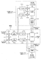
- FIG. 1 illustrates the case where the uplink of the second radio system 11 shares the frequency band assigned to the downlink of the first radio system 10. That is, in the first wireless system 10, the transmitter 12 transmits data to the receiver 13, and in the second wireless system 11, the transmitter 14 transmits data to the receiver 15 using the same frequency band.
- the second radio system 11 needs to communicate so as not to interfere with the communication of the first radio system 10, so the transmitter 14 of the second radio system is the receiver of the first radio system 10. Communication is performed using, for example, transmission power control so that the interference to 13 is equal to or less than a specified value. In this way, interference from the second radio system 11 to the first radio system 10 can be suppressed.
- the receiver 15 of the second radio system 11 receives the desired wave 21 of the own system transmitted from the transmitter 14, but simultaneously receives the signal arriving from the transmitter 12 of the first radio system as the interference wave 20. Is done. For this reason, the transmission characteristics of the receiver 15 of the second wireless system deteriorate due to interference coming from the transmitter 12 of the first wireless system.
- the transmitter 14 of the second radio system 11 is a mobile station such as a mobile communication terminal and the transmission frequency shares the frequency band of the first radio system 10
- the transmission power of the transmitter 14 is small and Since the antenna height is low, the separation distance between the first radio system 10 and the second radio system 11 is reduced, and the influence of the interference wave 20 coming from the transmitter 12 of the first radio system is increased.
- Patent Document 1 discloses a communication apparatus that suppresses the influence of interference waves by estimating channel characteristics of interference waves and desired waves using pilot subcarriers.
- Patent Document 1 or Non-Patent Document 1 described above discloses an interference suppression technique based on the premise that the first wireless system 10 and the second wireless system 11 have the same communication method according to FIG. Yes.
- the communication system between the interference station and the desired station is WiMAX.
- the transmitter 12 of the first wireless system 10 in FIG. 1 has a communication scheme different from that of the second wireless system 11, it can be an interference station for the receiver 15 of the second wireless system.
- the transmitter 12 of the first wireless system 10 is a television broadcast transmitter
- the transmission wave from the transmitter 12 is transmitted even if the receiver 15 of the second wireless system 11 is located outside the broadcast area. It may reach the receiver 15 as an interference wave 20.
- Patent Document 1 the interference suppression technology disclosed in Patent Document 1 or Non-Patent Document 1
- the present invention has been made to solve the above-described problems, and an object of the present invention is to effectively suppress the influence of interference waves from different types of radio systems when sharing the frequency bands of different types of radio systems. It is an object of the present invention to provide a wireless receiving apparatus and a wireless receiving method capable of performing the above.
- a radio reception apparatus is a radio reception apparatus in a second radio system that can use a frequency band assigned to the first radio system, and a communication method with respect to the second radio system is based on a received signal.
- First estimation means for generating a first channel estimation value of an interference wave component arriving from a different first radio system; and a second channel of a desired wave component received by the communication method of the second radio system from the received signal
- a second estimation unit configured to generate an estimation value
- an interference suppression unit configured to suppress the interference wave component using the first channel estimation value and the second channel estimation value.
- a radio reception method is a radio reception method of a radio reception device in a second radio system that can use a frequency band assigned to the first radio system, and is obtained from a received signal with the second radio system. Generates a first channel estimation value of an interference wave component arriving from the first radio system having a different communication scheme, and second channel estimation of a desired wave component received by the communication scheme of the second radio system from the received signal A value is generated, and the interference wave component is suppressed using the first channel estimation value and the second channel estimation value.
- a mobile station is a mobile station in a second radio system that can use a frequency band allocated to the first radio system, and the communication method differs from that of the second radio system based on a received signal.
- First estimation means for generating a first channel estimation value of an interference wave component arriving from the first wireless system; and a second channel estimation value of a desired wave component received by the communication method of the second wireless system from the received signal.
- second interference estimating means for suppressing the interference wave component using the first channel estimated value and the second channel estimated value.
- a communication system is a communication system including a wireless communication device in a second wireless system that can use a frequency band assigned to the first wireless system, wherein the wireless communication device is configured to receive the signal from the received signal.
- a first channel estimation value of an interference wave component arriving from the first wireless system, which is different in communication method from the second wireless system, and a second channel estimation value of a desired wave component received in the communication method of the second wireless system; Are generated, and the interference wave component is suppressed using the first channel estimation value and the second channel estimation value.
- the present invention it is possible to effectively suppress the influence of interference waves from different types of wireless systems and improve the interference suppression performance.
- FIG. 1 is a configuration diagram of a general communication system for explaining dynamic spectrum access.
- FIG. 2 is a block diagram showing a functional configuration of the wireless reception apparatus according to the first embodiment of the present invention.
- FIG. 3 is a block diagram showing a more detailed functional configuration of the channel estimation value conversion unit of the wireless reception apparatus shown in FIG.
- FIG. 4 is a flowchart for explaining the operation of the first channel estimation unit shown in FIG.
- FIGS. 5A to 5D are schematic spectrum diagrams for explaining frequency conversion and band cut-out processing in the radio reception apparatus shown in FIG. 6A and 6B are diagrams showing sampling intervals for explaining the operation of the sampling rate conversion unit shown in FIG.
- FIGS. 7A to 7D are waveform diagrams of channel estimation values for explaining the operation of the pasting correction unit shown in FIG.
- FIG. 8 is a block diagram showing a functional configuration of a radio reception apparatus according to the second embodiment of the present invention.
- FIG. 9 is a block diagram showing a more detailed functional configuration of the channel estimation value conversion unit of the radio reception apparatus shown in FIG.
- FIGS. 10A and 10B are diagrams showing subcarrier intervals for explaining the operation of the subcarrier interval conversion unit shown in FIG.
- FIG. 11 is a block diagram showing a functional configuration of a radio reception apparatus according to the third embodiment of the present invention.
- a wireless reception device that operates in a wireless system of a certain communication method performs channel estimation of interference waves from another wireless system with a different communication method, and is assigned to the other wireless system.
- the influence of interference waves from the other radio system is suppressed.
- the effective signal-to-interference noise power ratio of the wireless receiver can be improved and the throughput can be increased.
- the radio reception apparatus includes a plurality of antennas (here, two reception antennas a and b), a demodulation unit 100, a desired wave channel estimation unit 110, and An interference wave channel estimation unit 120 is included.
- the demodulator 100 receives the desired wave channel estimation value Es obtained by the desired wave channel estimation unit 110 and the interference wave channel estimation value Ei obtained by the interference wave channel estimation unit 120, and receives the received signal in which the interference component is suppressed. Is generated.
- Demodulator 100 frequency oscillator 101 generates an oscillation signal of a frequency f 2, the frequency conversion section 102a and 102b, AD (Analog-to- Digital) conversion section 103a and 103b, the sampling rate conversion unit 104a and 104b, and equalization Part 105.
- AD Analog-to- Digital
- Desired wave channel estimator 110 has pilot correlator 111, and determines the desired wave from the correlation between the digital received signals output from sampling rate converters 104a and 104b and the pilot code of the second radio system to which the radio receiver belongs.
- a channel estimate Es is generated.
- the interference wave channel estimation unit 120 includes sampling rate conversion units 121a and 121b, a frequency oscillator 122, frequency conversion units 123a and 123b, a pilot correlation unit 124, and a channel estimation value conversion unit 125.
- Sampling rate converters 121a and 121b receive digital received signals from AD converters 103a and 103b of demodulator 100, respectively.
- the channel estimation value conversion unit 125 includes a frequency oscillator 201, frequency conversion units 202a and 202b, a filter unit 203, a sampling rate conversion unit 204, and a path timing correction unit 205.
- the pilot correlator 124 generates an interference wave channel estimation value from the correlation between the digital received signal output from the frequency converters 123a and 123b and the pilot code of the first radio system, and uses the channel estimation value as a channel.
- the estimated value conversion unit 125 generates a channel estimated value Ei of the interference wave by performing conversion so as to be suitable for the second wireless system.
- the demodulator 100, the desired wave channel estimator 110, and the interference wave channel estimator 120 are described as functional blocks.
- the present invention is not limited to this configuration.
- the sampling rate conversion units 104a and 104b and the equalization unit 105, the desired wave channel estimation unit 110, and the interference wave channel estimation unit 120 of the demodulation unit 100 can be configured as one circuit chip.
- the program can be realized by executing the program on a program control processor such as a CPU (Central Processing Unit).
- a program control processor such as a CPU (Central Processing Unit).
- the frequency oscillator 101 outputs to the second radio system receiver signal having a center frequency f 2 of generating a frequency signal frequency conversion unit 102a and 102b.
- Frequency conversion unit 102a and 102b respectively received by the frequency signal and the reception antennas a and b of frequency f 2 RF (Radio-Frequency) received signal and the respectively input, converts each RF reception signal to a baseband signal ( Operation A01).
- the baseband signals thus obtained are respectively output to the AD conversion units 103a and 103b and converted into digital signals (operation A02).
- These digital signals are converted into sampling rates of the sampling rate conversion units 104a and 104b and the interference wave channel estimation unit 120.
- the data are output to conversion units 121a and 121b, respectively.
- the sampling rate converters 104a and 104b convert the sampling rates of the digital reception signals input from the AD converters 103a and 103b, respectively, to predetermined sampling rates suitable for demodulation of the second wireless system.
- the digital signal converted to a predetermined sampling rate is output to pilot correlation section 111 and equalization section 105, respectively.
- the pilot correlator 111 performs correlation processing between the digital received signal converted to the predetermined sampling rate and the predetermined pilot code of the second radio system, and estimates the channel of the desired wave transmitted from the transmitter of the second radio system Find the value.
- the channel estimation value Es of the desired wave thus obtained is output to the equalization unit 105.
- sampling rate conversion sections 121a and 121b receive the digital signals output from AD conversion sections 103a and 103b, respectively, and the sampling rate of the input digital signals is suitable for demodulation of the first radio system. Conversion to a predetermined sampling rate (operation A03). Sampling rate converters 121a and 121b output signals converted to a predetermined sampling rate to frequency converters 123a and 123b.
- the frequency oscillator 122 generates a frequency signal having a frequency f 2 ⁇ f 1 corresponding to the difference between the center frequency f 2 of the reception signal of the second radio system and the center frequency f 1 of the reception signal of the first radio system, and performs frequency conversion To the units 123a and 123b.
- the frequency converters 123a and 123b receive the baseband received signal subjected to the sampling rate conversion input from the sampling rate converters 121a and 121b, and multiply the frequency signal of the frequency f 2 -f 1 as will be described later. Frequency conversion is performed so that the center frequency of the received signal of one wireless system becomes 0 (operation A04).
- Frequency conversion sections 123a and 123b output the received signals of the first radio system subjected to frequency conversion to pilot correlation section 124.
- the pilot correlator 124 receives the frequency-converted received signals from the frequency converters 123a and 123b, respectively, and performs a correlation process with a predetermined pilot code of the first radio system to obtain a channel estimation value for the first radio system. (Operation A05), the first wireless system channel estimation value is output to the channel estimation value conversion unit 125.
- the channel estimation value conversion unit 125 receives the first radio system channel estimation value output from the pilot correlation unit 124, converts, for example, the center frequency and the sampling rate so as to conform to the demodulation parameters of the second radio system, Interference wave channel estimation value Ei converted to the demodulation parameter of the second radio system obtained in this way is output to equalization section 105 (operations B01 to B04, details will be described later).
- the equalization unit 105 receives the interference wave channel estimation value Ei from the channel estimation value conversion unit 125 and the channel estimation value Es of the desired wave from the pilot correlation unit 111, respectively. For example, based on the MMSE (Minimum Mean Square Error) standard An equalization weight that minimizes a square error between the pilot code of the second radio system and the equalized signal is generated. Then, equalization section 105 equalizes the received signals input from sampling rate conversion sections 104a and 104b using equalization weights, and outputs an equalized signal.
- MMSE Minimum Mean Square Error
- the first radio system 10 and the second radio system 11 have different demodulation parameters (center frequency, sampling rate, and system bandwidth).
- a channel estimation value conversion process for matching the channel estimation value of the received wave from the first wireless system with the demodulation parameter of the second wireless system is required.
- the operation of the channel estimation value conversion unit 125 will be described.
- the frequency oscillating unit 201 of the channel estimation value converting unit 125 has a frequency f 1 ⁇ f 2 corresponding to the difference between the center frequency f 1 of the received signal of the first radio system and the center frequency f 2 of the received signal of the second radio system. Are output to the frequency converters 202a and 202b.
- the frequency conversion units 202a and 202b multiply the first radio system channel estimation values E1-a and E1-b input from the pilot correlation unit 124 by the frequency signal of the frequency f 1 -f 2 to thereby obtain the first radio system.
- the channel estimation values E1-a and E1-b are returned to the frequencies before the frequency conversion by the frequency conversion units 123a and 123b (operation B01 in FIG. 4).
- the frequency conversion units 202a and 202b output the frequency-converted first radio system channel estimation value to the filter unit 203.
- the filter unit 203 performs a process of cutting out the frequency-converted first radio system channel estimation value by the demodulation bandwidth of the second radio system (operation B02), and the sampling rate conversion unit 204 converts the cut-out first radio system channel estimation value. Output to.
- the sampling rate conversion unit 204 converts the extracted first radio system channel estimation value from the sampling interval of the first radio system to the sampling interval of the second radio system (operation B03). As will be described later, for example, interpolation processing is used to convert the sampling interval.
- the sampling rate conversion unit 204 outputs the first radio system channel estimation value subjected to the sampling conversion to the path timing correction unit 205.
- the path timing correction unit 205 delay-shifts the first wireless system channel estimated value obtained by converting the sampling interval by a time amount corresponding to the path timing ⁇ of the propagation path of the first wireless system and the second wireless system, thereby correcting the path timing.
- the first radio system channel estimation value thus output is output to equalization section 105 as interference wave channel estimation values Ei-a and Ei-b (operation B04).
- FIG. 5A shows the spectrum of the received signal output from the frequency conversion units 102a and 102b of the demodulation unit 100, where the horizontal axis represents frequency and the vertical axis represents power.
- the center frequency of the spectrum 502 of the received signal of the second wireless system is 0, and the center frequency of the spectrum 501 of the received signal of the first wireless system is located at f1-f2.
- the diagonal lines indicate the overlapping frequency region of the spectrum 502 of the reception signal of the second wireless system and the spectrum 501 of the reception signal of the first wireless system.
- FIG. 5B shows the spectrum of the received signal output from the frequency converters 123a and 123b of the interference wave channel estimation unit 120.
- the spectrum 501 of the reception signal of the first wireless system is arranged so that the center frequency becomes 0 by the frequency conversion processing of the frequency conversion units 123a and 123b.
- the reason why the center frequency of the spectrum 501 of the first wireless system reception signal is set to 0 is that the pilot correlation unit 124 performs pilot correlation processing.
- FIG. 5C shows the channel estimation value 503 of the first radio system output from the frequency conversion units 202 a and 202 b of the channel estimation value conversion unit 125.
- the center frequency of the channel estimation value 503 of the first radio system is arranged at f 1 -f 2 . This is a process for returning the channel estimation value of the first radio system to the frequency observed in the second radio system by performing the reverse operation of the frequency conversion process of the frequency converters 123a and 123b.
- FIG. 5D shows the channel estimation value of the first radio system output from the filter unit 203 of the channel estimation value conversion unit 125.
- the channel estimation value 503 of the first radio system only the channel estimation value of the frequency overlapping the demodulation band 502 of the second radio system is cut out and output.
- FIG. 6 is a diagram schematically showing the processing of the sampling rate conversion unit 204 of the channel estimation value conversion unit 125, and the horizontal axis represents time.
- FIG. 6A shows the sampling interval of the channel estimation value of the first radio system
- FIG. 6B shows the sampling interval of the channel estimation value of the second radio system.
- the sampling rate conversion unit 204 matches the sampling interval of the channel estimation value of the first radio system with the sampling interval of the channel estimation value of the second radio system by, for example, interpolation processing.
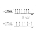
- FIG. 7 is a diagram schematically illustrating an example of the operation of the path timing correction unit 205 of the channel estimation value conversion unit 125, where the horizontal axis represents time and the vertical axis represents power.
- FIG. 7A shows the channel estimation value of the first radio system before the path timing correction
- FIG. 7B shows the channel estimation value of the second radio system before the path timing correction
- FIG. 7D shows the channel estimation value of the second radio system after the pastaming correction, respectively.
- the first radio system and the second radio system operate independently in synchronization with the incoming signals of the respective systems.
- the path timing correction unit 205 delay-shifts the channel estimation value of the first radio system according to the path timing difference ⁇ of the propagation paths of the first radio system and the second radio system.
- the first radio system channel estimation value thus corrected in path timing is output to the equalization unit 105 as interference wave channel estimation values Ei-a and Ei-b that can be used in the second radio system.
- the equalization unit 105 equalizes the received signals input from the sampling rate conversion units 104a and 104b using the interference wave channel estimation values Ei-a and Ei-b, and converts the equalized signal into signals. Output.
- the channel of the first radio system that is an interference wave The estimated value can be used in the second radio system, and interference waves coming from the first radio system can be suppressed with high accuracy by multi-antenna spatial filtering. Thereby, the effective signal-to-interference noise power ratio of the second radio system can be improved, and the throughput can be improved.
- the influence of interference waves coming from the first radio system is reduced, the separation distance between the first radio system transmitter and the second radio system receiver can be reduced, and the coverage in the frequency sharing band of the second radio system is expanded. it can.
- the receivers disclosed in Patent Document 1 and Non-Patent Document 1 if the demodulation parameters of the first radio system and the second radio system are the same, channel estimates of desired waves and interference waves can be obtained.
- the second radio system cannot acquire the channel estimation value of the interference wave coming from the first radio system. For this reason, the receiver disclosed in Non-Patent Document 1 cannot generate equalization weights in consideration of interference waves and cannot obtain the interference wave suppression effect.
- the radio reception apparatus performs channel estimation acquisition and equalization processing by frequency domain processing assuming an OFDM (Orthogonal Frequency Division Multiplexing) based transmission scheme.
- the first radio system 10 and the second radio system 11 in FIG. 1 have different communication parameters, and here, demodulation parameters (center frequency, subcarrier interval and system bandwidth) are different.
- demodulation parameters center frequency, subcarrier interval and system bandwidth
- the radio reception apparatus of the second radio system 11 can be applied as any receiving unit of the mobile station or the base station of the second radio system 11 in FIG.
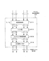
- the radio reception apparatus includes a demodulation section 800, a desired wave channel estimation section 810, and an interference wave channel estimation section 820 of the second radio system.
- the demodulator 800 includes a frequency oscillator 801, frequency converters 802a and 802b, AD converters 803a and 803b, sampling rate converters 804a and 804b, Fourier transformers 805a and 805b, and an equalizer 806.
- Desired wave channel estimation section 810 is configured from pilot correlation section 811 of the second radio system.
- Interference wave channel estimation unit 820 includes sampling rate conversion units 821a and 821b, frequency oscillator 822, frequency conversion units 823a and 823b, Fourier transform units 824a and 824b, a pilot correlation unit 825 of the first radio system, A channel estimation value conversion unit 826 of one radio system.
- the channel estimation value conversion unit 826 includes a frequency conversion unit 911, a filter unit 912, a subcarrier interval conversion unit 913, and a cyclic delay shift unit 914.
- Frequency oscillator 801 generates a frequency signal of a frequency f 2 corresponding to the center frequency of the second radio system receiver signal, and outputs the generated frequency signal to the frequency conversion section 802a and 802b.
- Frequency conversion unit 802a and 802b are an RF reception signal received at the antenna a and b is converted into a baseband received signal by multiplying the frequency signal of the frequency f 2, each of the baseband signals AD converter 803a and Output to 803b.
- the baseband received signals are converted from analog signals to digital signals by AD conversion units 803a and 803b, respectively, and output to sampling rate conversion units 804a and 804b and sampling rate conversion units 821a and 821b of interference wave channel estimation unit 820, respectively.
- Sampling rate conversion units 804a and 804b convert the sampling rate of the input digital signal to a predetermined sampling rate suitable for demodulation of the second wireless system, and output the result to Fourier transformation units 805a and 805b, respectively.
- Fourier transform sections 805a and 805b convert the reception signal subjected to the sampling rate conversion from a time domain signal to a frequency domain signal.
- FFT Fast Fourier Transform
- DFT Discrete Fourier Transform
- the pilot correlation unit 811 performs correlation processing with a received signal in the frequency domain using a predetermined pilot code of the second radio system, obtains a channel estimation value of a desired wave received from the second radio system transmitter, and equalizes Output to 806.
- a desired wave channel estimation value vector H 0 (k) of subcarrier k (k 0, 1,..., K ⁇ 1: K is an integer of 1 or more in terms of the number of points of Fourier transform sections 805a and 805b) is It is represented by
- R pich (k) is a received signal vector of a pilot block
- C 0 (k) is a pilot code in the frequency domain of the second radio system
- a suffix * indicates a complex conjugate.
- a CAZAC (Constant Amplitude Zero Auto Correlation) code that does not cause noise enhancement in correlation processing is used as a pilot code.
- the sampling rate conversion units 821a and 821b of the interference wave channel estimation unit 802 convert the sampling rate of the input digital signal into a predetermined sampling rate suitable for demodulation of the first wireless system, and send it to the frequency conversion units 823a and 823b, respectively.
- the frequency oscillator 822 generates a frequency signal having a frequency f 2 ⁇ f 1 corresponding to the difference between the center frequency f 2 of the reception signal of the second radio system and the center frequency f 1 of the reception signal of the first radio system, and performs frequency conversion The data are output to the units 823a and 823b, respectively.
- Frequency converters 823a and 823b multiply the sampling rate converted baseband received signal by the frequency signal of frequency f 2 -f 1 and perform frequency conversion so that the center frequency of the received signal of the first wireless system becomes zero. And output to Fourier transform units 824a and 824b, respectively.
- Fourier transform sections 824a and 824b convert the frequency-converted received signal from a time domain signal to a frequency domain signal, and output the frequency domain received signal to pilot correlation section 825, respectively.
- the pilot correlation unit 825 performs correlation processing with a received signal in the frequency domain using a predetermined pilot code of the first radio system, obtains a channel estimation value of the radio signal received from the first radio system, and a channel estimation value conversion unit To 826, respectively.
- the k caret in the expression is represented by ⁇ k. ).
- R pich ( ⁇ k) represents a received signal vector of a pilot block
- C u ( ⁇ k) represents a frequency domain pilot code in the transmitter u of the first radio system.
- u 0 indicates the transmitter (desired wave) of the second radio system
- u> 0 indicates the transmitter (interference wave) of the first radio system.
- the channel estimation value conversion unit 826 receives the channel estimation value H u ( ⁇ k), converts, for example, the center frequency and the sampling rate so as to conform to the demodulation parameters of the second radio system, and the interference wave obtained in this way.
- the channel estimation value is output to the equalization unit 806. The operation of the channel estimation value conversion unit 826 will be described later.
- the equalization unit 806 uses the desired wave channel estimation value input from the pilot correlation unit 811 and the interference wave channel estimation value input from the channel estimation value conversion unit 826 to calculate equalization weights in the frequency domain based on the MMSE standard, for example. Using the equalization weight, the frequency domain received signals input from the Fourier transform units 805a and 805b are equalized, and the equalized signal is output.
- ⁇ 2 is noise power
- I is a unit matrix
- H Hermitian conjugate
- the frequency conversion unit 911, the channel estimation value of the first radio system from the pilot correlation unit 825 H u ( ⁇ k) enter the frequency converting the channel estimation value H u ( ⁇ k) by frequency domain processing
- the frequency is returned to the frequency before frequency conversion in the unit 823 and output to the filter unit 912.
- the filter unit 912 performs processing for extracting the frequency-converted channel estimation value of the first radio system in the frequency domain with the demodulation bandwidth of the second radio system, and the channel estimation value thus extracted to the subcarrier interval conversion unit 913. Output.
- the subcarrier interval conversion unit 913 converts the extracted channel estimation value of the first radio system from the subcarrier interval of the first radio system to the subcarrier interval of the second radio system in the frequency domain, and converts the converted first radio system Are output to cyclic delay shift section 914. For example, an interpolation process is used for the conversion.
- the cyclic delay shift unit 914 uses the frequency estimated by the amount of time corresponding to the path timing ⁇ of the propagation path between the first radio system and the second radio system, for the channel estimation value of the first radio system in which the subcarrier interval is converted.
- the channel estimation value of the first radio system subjected to delay shift in the region is output to the equalization unit 806 as the interference wave channel estimation value.
- FIG. 10 is a diagram showing how the subcarrier interval conversion unit 913 performs processing, and the horizontal axis represents time.
- FIG. 10A shows the subcarrier interval of the channel estimation value of the first radio system
- FIG. 10B shows the subcarrier interval of the channel estimation value of the second radio system.
- the subcarrier interval conversion unit 913 matches the subcarrier interval of the channel estimation value of the first radio system with the subcarrier interval of the channel estimation value of the second radio system by interpolation processing, for example.
- the second embodiment of the present invention even if the demodulation parameters of the first radio system and the second radio system are different, the first interference wave is generated by the frequency domain processing.
- the channel estimation value of the radio system can be used in the second radio system, and interference waves coming from the first radio system can be suppressed with high accuracy by multi-antenna spatial filtering. Thereby, the effective signal-to-interference noise power ratio of the second radio system can be improved, and the throughput is increased.
- the influence of interference waves coming from the first radio system is reduced, the separation distance between the first radio system transmitter and the second radio system receiver can be reduced, and the coverage in the frequency sharing band of the second radio system is expanded. it can.
- the OFDM-based wireless reception device has been described as an example. However, the second embodiment can be applied to another transmission method, for example, DFT-Spread OFDM.
- the radio receiving apparatus includes a frequency oscillator 1001, frequency conversion units 1002a and 1002b, AD conversion units 1003a and 1003b, sampling rate conversion units 1004a and 1004b, a pilot correlation unit 1005, and the like. , A third interference wave channel estimation unit 1007 and a fourth interference wave channel estimation unit 1008.
- Frequency oscillator 1001 generates a frequency signal having a center frequency f 2 of the second radio system received signal, and outputs to the frequency converter 1002a and 1002b.
- Frequency converter 1002a and 1002b are the RF signal received by the antenna a and b is converted into a baseband received signal by multiplying the frequency signal of the frequency f 2, the baseband received signal to the AD conversion section 1003a and 1003b Output each.
- the baseband signal is converted into a digital signal by AD converters 1003a and 1003b, and is output to sampling rate converters 1004a and 1004b, respectively.
- Sampling rate conversion units 1004a and 1004b convert the sampling rate of the digital signal to a predetermined sampling rate suitable for demodulation, and output the signal converted to the predetermined sampling rate to pilot correlation unit 1005 and equalization unit 1006.
- the pilot correlator 1005 performs correlation processing between the received signal subjected to the sampling rate conversion and each of the pilot code of the first radio system and the pilot code of the second radio system, and a desired wave channel from the second radio system transmitter.
- the estimation value and the interference wave channel estimation value from the first radio system transmitter are obtained, and the desired wave channel estimation value and the interference wave channel estimation value are output to the equalization unit 1006.
- the third interference wave channel estimation unit 1007 generates a third interference wave channel estimation value from a third radio system transmitter having a demodulation parameter different from that of the second radio system
- the fourth interference wave channel estimation unit 1008 A fourth interference channel estimation value is generated from a fourth wireless system transmitter having a demodulation parameter different from that of the wireless system.
- the third interference wave channel estimation unit 1007 and the fourth interference wave channel estimation unit 1008 basically have the same configuration as the interference wave channel estimation unit 120 shown in FIG. 2 except that the demodulation parameters are different. Detailed description is omitted.
- the equalization unit 1006 receives the channel estimation value of the desired wave and the channel estimation value of the interference wave from the pilot correlation unit 1005, and receives the third and fourth interference wave channel estimation units 1007 and 1008 from the third interference wave channel estimation unit 1008. Equalization weights are generated by inputting channel estimates of four interference waves.
- the equalization unit 1006 equalizes the reception signals input from the sampling rate conversion units 1004a and 1004b using equalization weights, and outputs an equalized signal.
- the radio receiving apparatus acquires the interference wave channel estimation value and the channel estimation value of the desired wave even when there are interference waves from the same type of radio system and / or different types of radio systems.
- the equalization weight that minimizes the square error between the pilot code and the equalized signal can be generated, and the effect of effectively suppressing interference from other radio systems can be obtained.
- the present invention can also be applied to a wireless receiving device having two or more receiving antennas.
- the radio reception apparatus in the case of SIMO (Single Input Multiple Output) has been described as an example.
- the second radio system is applied to the radio reception apparatus in the case where the second radio system is MIMO (Multiple Input Multiple Output). You can also
- the first wireless system has been described as an interference system, but the receiving apparatus of the present invention can also be applied to the first wireless system.
- the above embodiment can be realized as predetermined hardware, for example, a circuit, or realized by software so as to be controlled and operated by a computer circuit (for example, CPU) (not shown) based on a control program. You can also.
- these control programs are stored in a wireless receiver or a storage medium inside the baseband unit (for example, a ROM (Read Only Memory) or a hard disk), or an external storage medium (for example, a removable medium or a removable disk). And read and executed by the computer circuit.
- the present invention can be suitably applied to any device, method, or program that needs to receive a radio signal through frequency sharing.
Landscapes
- Engineering & Computer Science (AREA)
- Computer Networks & Wireless Communication (AREA)
- Signal Processing (AREA)
- Power Engineering (AREA)
- Noise Elimination (AREA)
- Mobile Radio Communication Systems (AREA)
- Cable Transmission Systems, Equalization Of Radio And Reduction Of Echo (AREA)
Abstract
Description
以下、本発明の第1実施形態について図面を参照しながら詳細に説明する。ただし、無線アクセス方式としてシングルキャリアおよびマルチキャリア伝送システムを例示し、図1における第2無線システム11の無線受信装置が第1無線システム10に割り当てられた周波数帯を共用するものとする。図1における第1無線システム10と第2無線システム11とは異なる通信パラメータを有し、ここでは復調パラメータ(中心周波数、サンプリングレートおよびシステム帯域幅)が異なるものとする。なお、第2無線システム11の無線受信装置は、図1における第2無線システム11の移動局あるいは基地局のいずれの受信部としても適用可能である。 1. First Embodiment Hereinafter, a first embodiment of the present invention will be described in detail with reference to the drawings. However, single-carrier and multi-carrier transmission systems are illustrated as wireless access methods, and the wireless reception device of the second wireless system 11 in FIG. 1 shares the frequency band assigned to the first
図2において、本発明の第1実施形態に係る無線受信装置は、複数のアンテナ(ここでは2本の受信アンテナaおよびb)、復調部100、所望波チャネル推定部110および干渉波チャネル推定部120を有する。復調部100は、所望波チャネル推定部110により得られた所望波チャネル推定値Esと干渉波チャネル推定部120により得られた干渉波チャネル推定値Eiとを入力して干渉成分を抑制した受信信号を生成する。 1.1) Configuration In FIG. 2, the radio reception apparatus according to the first embodiment of the present invention includes a plurality of antennas (here, two reception antennas a and b), a
図4を部分的に参照しながら、図2に示す無線受信装置の動作について説明する。 1.2) Operation The operation of the wireless reception device shown in FIG. 2 will be described with reference to FIG. 4 partially.
上述したように、第1無線システム10と第2無線システム11とは異なる復調パラメータ(中心周波数、サンプリングレートおよびシステム帯域幅)を有するので、パイロット相関部124で得られた第1無線システムからの受信波のチャネル推定値を第2無線システムの復調パラメータに整合させるチャネル推定値変換処理が必要である。以下、チャネル推定値変換部125の動作を説明する。 1.3) Channel Estimated Value Conversion As described above, the
図5(a)は復調部100の周波数変換部102aおよび102bから出力される受信信号のスペクトラムを示し、横軸は周波数、縦軸は電力を表す。第2無線システムの受信信号のスペクトラム502の中心周波数は0、第1無線システムの受信信号のスペクトラム501の中心周波数はf1-f2に配置されている。斜線は第2無線システムの受信信号のスペクトラム502と第1無線システムの受信信号のスペクトラム501の重複周波数領域を示す。 1.4) Frequency Conversion and Band Extraction Processing FIG. 5A shows the spectrum of the received signal output from the
図6はチャネル推定値変換部125のサンプリングレート変換部204の処理を模式的に示した図であり、横軸は時間を表す。図6(a)は第1無線システムのチャネル推定値のサンプル間隔を示し、図6(b)は第2無線システムのチャネル推定値のサンプル間隔を示す。サンプリングレート変換部204は、第1無線システムのチャネル推定値のサンプル間隔を例えば補間処理により第2無線システムのチャネル推定値のサンプル間隔に一致させる。 1.5) Sampling Rate Conversion FIG. 6 is a diagram schematically showing the processing of the sampling
図7はチャネル推定値変換部125のパスタイミング補正部205の動作の一例を模式的に示した図であり、横軸は時間、縦軸は電力を表す。図7(a)はパスタイミング補正前の第1無線システムのチャネル推定値、図7(b)はパスタミング補正前の第2無線システムのチャネル推定値、図7(c)はパスタミング補正後の第1無線システムのチャネル推定値、図7(d)はパスタミング補正後の第2無線システムのチャネル推定値をそれぞれ示す。 1.6) Path Timing Correction FIG. 7 is a diagram schematically illustrating an example of the operation of the path timing
以上説明したように、本発明の第1実施形態によれば、第1無線システムと第2無線システムの復調パラメータが異なる場合においても、干渉波である第1無線システムのチャネル推定値を第2無線システムにおいて使用することができ、複数アンテナ空間フィルタリングにより第1無線システムから到来する干渉波を高精度に抑圧できる。これにより、第2無線システムの実効的な信号対干渉雑音電力比を向上でき、スループットを向上させることができる。また、第1無線システムから到来する干渉波の影響が小さくなるため、第1無線システム送信機および第2無線システム受信機の離隔距離を小さくでき、第2無線システムの周波数共用帯域におけるカバレッジを拡大できる。 1.7) Effect As described above, according to the first embodiment of the present invention, even if the demodulation parameters of the first radio system and the second radio system are different, the channel of the first radio system that is an interference wave The estimated value can be used in the second radio system, and interference waves coming from the first radio system can be suppressed with high accuracy by multi-antenna spatial filtering. Thereby, the effective signal-to-interference noise power ratio of the second radio system can be improved, and the throughput can be improved. In addition, since the influence of interference waves coming from the first radio system is reduced, the separation distance between the first radio system transmitter and the second radio system receiver can be reduced, and the coverage in the frequency sharing band of the second radio system is expanded. it can.
以下、本発明の第2実施形態について図面を参照しながら詳細に説明する。ただし、図1における第2無線システム11の無線受信装置が第1無線システム10に割り当てられた周波数帯を共用するものとする。本発明の第2実施形態に係る無線受信装置では、OFDM(Orthogonal Frequency Division Multiplexing)ベースの伝送方式を想定して周波数領域の処理によりチャネル推定の取得および等化処理を行う。図1における第1無線システム10と第2無線システム11とは異なる通信パラメータを有し、ここでは復調パラメータ(中心周波数、サブキャリア間隔およびシステム帯域幅)が異なるものとする。なお、第2無線システム11の無線受信装置は、図1における第2無線システム11の移動局あるいは基地局のいずれの受信部としても適用可能である。 2. Second Embodiment Hereinafter, a second embodiment of the present invention will be described in detail with reference to the drawings. However, it is assumed that the wireless reception device of the second wireless system 11 in FIG. 1 shares the frequency band assigned to the
図8において、本実施形態による無線受信装置は、第2無線システムの復調部800と、所望波チャネル推定部810と、干渉波チャネル推定部820とを有する。復調部800は、周波数発振器801と、周波数変換部802aおよび802bと、AD変換部803aおよび803bと、サンプリングレート変換部804aおよび804bと、フーリエ変換部805aおよび805bと、等化部806と、を有する。所望波チャネル推定部810は、第2無線システムのパイロット相関部811から構成される。 2.1) Configuration In FIG. 8, the radio reception apparatus according to the present embodiment includes a
以下、図8および図9を参照しながら、本実施形態による無線受信装置の動作を説明する。 2.2) Operation Hereinafter, the operation of the radio reception apparatus according to the present embodiment will be described with reference to FIGS. 8 and 9.


ここで、σ2は雑音電力、Iは単位行列、添字Hはエルミート共役を示す。
Here, σ 2 is noise power, I is a unit matrix, and the subscript H is Hermitian conjugate.
上述したように、第1無線システム10と第2無線システム11とは異なる復調パラメータ(中心周波数、サブキャリア間隔およびシステム帯域幅)を有するので、パイロット相関部825で得られた第1無線システムからの受信波のチャネル推定値を第2無線システムの復調パラメータに整合させるチャネル推定値変換処理が必要である。以下、チャネル推定値変換部826の動作を説明する。 2.3) Channel estimation value conversion Since the
図10はサブキャリア間隔変換部913の処理の様子を示した図であり、横軸は時間を表す。図10(a)は第1無線システムのチャネル推定値のサブキャリア間隔を示し、図10(b)は第2無線システムのチャネル推定値のサブキャリア間隔を示す。サブキャリア間隔変換部913は、第1無線システムのチャネル推定値のサブキャリア間隔を例えば補間処理により第2無線システムのチャネル推定値のサブキャリア間隔に一致させる。 2.4) Subcarrier Interval Conversion FIG. 10 is a diagram showing how the subcarrier
以上説明したように、本発明の第2実施形態によれば、第1無線システムと第2無線システムの復調パラメータが異なる場合においても周波数領域の処理により干渉波である第1無線システムのチャネル推定値を第2無線システムにおいて使用でき、複数アンテナ空間フィルタリングにより第1無線システムから到来する干渉波を高精度に抑圧できる。これにより、第2無線システムの実効的な信号対干渉雑音電力比を向上でき、スループットが増大する。また、第1無線システムから到来する干渉波の影響が小さくなるため、第1無線システム送信機および第2無線システム受信機の離隔距離を小さくでき、第2無線システムの周波数共用帯域におけるカバレッジを拡大できる。なお、第2実施形態ではOFDMベースの無線受信装置を例に挙げて説明したが、別の伝送方式、例えばDFT-Spread OFDMにも適用することができる。 2.5) Effect As described above, according to the second embodiment of the present invention, even if the demodulation parameters of the first radio system and the second radio system are different, the first interference wave is generated by the frequency domain processing. The channel estimation value of the radio system can be used in the second radio system, and interference waves coming from the first radio system can be suppressed with high accuracy by multi-antenna spatial filtering. Thereby, the effective signal-to-interference noise power ratio of the second radio system can be improved, and the throughput is increased. In addition, since the influence of interference waves coming from the first radio system is reduced, the separation distance between the first radio system transmitter and the second radio system receiver can be reduced, and the coverage in the frequency sharing band of the second radio system is expanded. it can. In the second embodiment, the OFDM-based wireless reception device has been described as an example. However, the second embodiment can be applied to another transmission method, for example, DFT-Spread OFDM.
上記実施形態では、図1に示す第1無線システム10と第2無線システム11における無線受信装置を例示したが、異種無線システムが複数個、同種無線システムも複数個存在する場合であっても本発明は適用可能である。以下、本発明の第3実施形態として、2つの同種無線システム(第1、第2無線システム)と2つの異種無線システム(第3、第4無線システム)が存在し、本実施形態による無線受信装置が第2無線システムに属する場合を説明する。 3. Third Embodiment In the above embodiment, the wireless receivers in the
以上の実施形態では、第2無線システムの受信アンテナ2本の場合を例に挙げて説明したが、本発明は受信アンテナ2本以上の無線受信装置にも適用することができる。また、第2無線システムにおいてはSIMO(Single Input Multiple Output)の場合の無線受信装置を例に挙げて説明したが、第2無線システムがMIMO(Multiple Input Multiple Output)の場合の無線受信装置に適用することもできる。 4). Others In the above embodiment, the case of two receiving antennas of the second wireless system has been described as an example. However, the present invention can also be applied to a wireless receiving device having two or more receiving antennas. In the second radio system, the radio reception apparatus in the case of SIMO (Single Input Multiple Output) has been described as an example. However, the second radio system is applied to the radio reception apparatus in the case where the second radio system is MIMO (Multiple Input Multiple Output). You can also
11 第2無線システムのサービスエリア
12 第1無線システムの送信機
13 第1無線システムの受信機
14 第2無線システムの送信機
15 第2無線システムの受信機
100 復調部
101 周波数発振器
102a、102b 周波数変換部
103a、103b AD変換部
104a、104b サンプリングレート変換部
105 等化部
110 所望波チャネル推定部
111 パイロット相関部
120 干渉波チャネル推定部
121a、121b サンプリングレート変換部
122 周波数発振器
123a、123b 周波数変換部
124 パイロット相関部
125 チャネル推定値変換部
201 周波数発振器
202a、202b 周波数変換部
203 フィルタ部
204 サンプリングレート変換部
205 パスタイミング補正部
501 第1無線システムの受信信号
502 第2無線システムの受信信号
503 第1無線システムのチャネル推定値
800 復調部
801 周波数発振器
802a、802b 周波数変換部
803a、803b AD変換部
804a、804b サンプリングレート変換部
805a、805b フーリエ変換部
806 等化部
810 所望波チャネル推定部
811 パイロット相関部
820 干渉波チャネル推定部
821a、821b サンプリングレート変換部
822 周波数発振器
823a、823b 周波数変換部
824a、824b フーリエ変換部
825 パイロット相関部
816 チャネル推定値変換部
911 周波数変換部
912 フィルタ部
913 サブキャリア間隔変換部
914 巡回遅延シフト部
1001 周波数発振器
1002a、1002b 周波数変換部
1003a、1003b AD変換部
1004a、1004b サンプリングレート変換部
1005 パイロット相関部
1006 等化部
1007 第3干渉波チャネル推定部
1008 第4干渉波チャネル推定部 DESCRIPTION OF SYMBOLS 10 1st wireless system service area 11 2nd wireless system service area 12 1st wireless system transmitter 13 1st wireless system receiver 14 2nd wireless system transmitter 15 2nd wireless system receiver 100 Demodulation Unit 101 frequency oscillators 102a and 102b frequency conversion units 103a and 103b AD conversion units 104a and 104b sampling rate conversion unit 105 equalization unit 110 desired wave channel estimation unit 111 pilot correlation unit 120 interference wave channel estimation units 121a and 121b sampling rate conversion unit 122 Frequency oscillators 123a and 123b Frequency conversion unit 124 Pilot correlation unit 125 Channel estimation value conversion unit 201 Frequency oscillators 202a and 202b Frequency conversion unit 203 Filter unit 204 Sampling rate conversion unit 205 Path timing Correction unit 501 First wireless system received signal 502 Second wireless system received signal 503 First wireless system channel estimation value 800 Demodulator 801 Frequency oscillator 802a, 802b Frequency converter 803a, 803b AD converter 804a, 804b Sampling Rate converters 805a and 805b Fourier transformer 806 Equalizer 810 Desired wave channel estimator 811 Pilot correlation unit 820 Interference wave channel estimator 821a and 821b Sampling rate converter 822 Frequency oscillators 823a and 823b Frequency converters 824a and 824b Fourier transform Unit 825 pilot correlation unit 816 channel estimation value conversion unit 911 frequency conversion unit 912 filter unit 913 subcarrier interval conversion unit 914 cyclic delay shift unit 1001 frequency oscillator 1002a, 100 b frequency converter 1003a, 1003b AD conversion section 1004a, 1004b sampling rate conversion unit 1005 pilot correlation unit 1006 equalization section 1007 third interference signal channel estimation unit 1008 fourth interference wave channel estimator
Claims (12)
- 第1無線システムに割り当てられた周波数帯を利用することができる第2無線システムにおける無線受信装置であって、
受信信号から、前記第2無線システムとは通信方式が異なる前記第1無線システムから到来した干渉波成分の第1チャネル推定値を生成する第1推定手段と、
前記受信信号から、前記第2無線システムの通信方式で受信した所望波成分の第2チャネル推定値を生成する第2推定手段と、
前記第1チャネル推定値と前記第2チャネル推定値とを用いて前記干渉波成分を抑圧する干渉抑圧手段と、
を有することを特徴とする無線受信装置。 A radio receiving apparatus in a second radio system capable of using a frequency band assigned to the first radio system,
First estimation means for generating, from a received signal, a first channel estimation value of an interference wave component arriving from the first wireless system having a communication method different from that of the second wireless system;
Second estimation means for generating, from the received signal, a second channel estimation value of the desired wave component received by the communication method of the second wireless system;
Interference suppression means for suppressing the interference wave component using the first channel estimation value and the second channel estimation value;
A wireless receiver characterized by comprising: - 前記第1推定手段は、
前記受信信号から前記第1無線システムの通信方式に従ってチャネル推定値を生成するチャネル推定値生成手段と、
前記チャネル推定値を前記第2無線システムの通信方式に従ったチャネル推定値に変換することで前記第1チャネル推定値を生成するチャネル推定値変換手段と、
を有することを特徴とする請求項1に記載の無線受信装置。 The first estimating means includes
Channel estimation value generating means for generating a channel estimation value from the received signal according to the communication method of the first wireless system;
Channel estimation value conversion means for generating the first channel estimation value by converting the channel estimation value into a channel estimation value according to a communication scheme of the second wireless system;
The wireless receiving device according to claim 1, comprising: - 前記チャネル推定値変換手段は、
前記チャネル推定値の配置周波数を前記第2無線システムの通信方式に従って周波数変換する周波数変換手段と、
前記周波数変換されたチャネル推定値を第2無線システムの通信方式と同一の復調帯域で切り出すフィルタ手段と、
前記切り出されたチャネル推定値のサンプリングレートを前記第2無線システムの通信方式と同じサンプリングレートに変換するサンプリングレート変換手段と、
前記サンプリングレート変換されたチャネル推定値を第1無線システムおよび第2無線システムの伝搬路のパスタイミングに従って時間補正する時間補正手段と、
を備えたことを特徴とする請求項2に記載の無線受信装置。 The channel estimation value conversion means includes:
Frequency conversion means for converting the frequency of arrangement of the channel estimation value according to a communication method of the second wireless system;
Filter means for cutting out the frequency-converted channel estimation value in the same demodulation band as the communication system of the second wireless system;
Sampling rate conversion means for converting the sampling rate of the extracted channel estimation value to the same sampling rate as the communication method of the second wireless system;
Time correction means for correcting the sampling rate converted channel estimation value according to the path timing of the propagation path of the first radio system and the second radio system;
The wireless reception device according to claim 2, further comprising: - 前記第1推定手段、前記第2推定手段および前記干渉抑圧手段の各々は周波数領域の処理を実行することを特徴とする請求項1-3のいずれか1項に記載の無線受信装置。 The radio reception apparatus according to any one of claims 1 to 3, wherein each of the first estimation unit, the second estimation unit, and the interference suppression unit performs frequency domain processing.
- 前記第1無線システムと前記第2無線システムとは、システムの中心周波数、サンプリングレートおよび/またはシステム帯域幅に関する通信パラメータが互いに異なることを特徴とする請求項1-4のいずれか1項に記載の無線受信装置。 5. The communication system according to claim 1, wherein the first radio system and the second radio system have different communication parameters related to a center frequency, a sampling rate, and / or a system bandwidth of the system. Wireless receiver.
- 第1無線システムに割り当てられた周波数帯を利用することができる第2無線システムにおける無線受信装置の無線受信方法であって、
受信信号から、前記第2無線システムとは通信方式が異なる前記第1無線システムから到来した干渉波成分の第1チャネル推定値を生成し、
前記受信信号から、前記第2無線システムの通信方式で受信した所望波成分の第2チャネル推定値を生成し、
前記第1チャネル推定値と前記第2チャネル推定値とを用いて前記干渉波成分を抑圧する、
ことを特徴とする無線受信方法。 A wireless reception method of a wireless reception device in a second wireless system capable of using a frequency band assigned to the first wireless system,
From the received signal, a first channel estimation value of an interference wave component arriving from the first radio system having a communication method different from that of the second radio system is generated,
Generating a second channel estimation value of a desired wave component received by the communication method of the second wireless system from the received signal;
Suppressing the interference wave component using the first channel estimation value and the second channel estimation value;
A wireless reception method. - 前記第1チャネル推定値の生成ステップは、
前記受信信号から前記第1無線システムの通信方式に従ってチャネル推定値を生成するステップと、
前記チャネル推定値を前記第2無線システムの通信方式に従ったチャネル推定値に変換するステップと、
からなることを特徴とする請求項6に記載の無線受信方法。 The step of generating the first channel estimation value includes:
Generating a channel estimation value from the received signal according to a communication scheme of the first wireless system;
Converting the channel estimate into a channel estimate according to a communication scheme of the second wireless system;
The wireless reception method according to claim 6, comprising: - 前記チャネル推定値変換ステップは、
前記チャネル推定値の配置周波数を前記第2無線システムの通信方式に従って周波数変換するステップと、
前記周波数変換されたチャネル推定値を第2無線システムの通信方式と同一の復調帯域で切り出すステップと、
前記切り出されたチャネル推定値のサンプリングレートを前記第2無線システムの通信方式と同じサンプリングレートに変換するステップ、
前記サンプリングレート変換されたチャネル推定値を第1無線システムおよび第2無線システムの伝搬路のパスタイミングに従って時間補正するステップと、
からなることを特徴とする請求項7に記載の無線受信方法。 The channel estimation value conversion step includes:
Converting the frequency of arrangement of the channel estimation value according to a communication method of the second wireless system;
Cutting out the frequency-converted channel estimation value in the same demodulation band as the communication system of the second wireless system;
Converting the sampling rate of the extracted channel estimation value to the same sampling rate as the communication method of the second wireless system;
Correcting the sampling rate converted channel estimation value according to the path timing of the propagation path of the first radio system and the second radio system;
The wireless reception method according to claim 7, comprising: - 前記第1チャネル推定値の生成ステップ、前記第2チャネル推定値の生成ステップおよび前記干渉抑圧ステップの各々は周波数領域の処理を実行することを特徴とする請求項6-8のいずれか1項に記載の無線受信方法。 9. The method according to claim 6, wherein each of the first channel estimation value generation step, the second channel estimation value generation step, and the interference suppression step performs frequency domain processing. The wireless reception method described.
- 前記第1無線システムと前記第2無線システムとは、システムの中心周波数、サンプリングレートおよび/またはシステム帯域幅に関する通信パラメータが互いに異なることを特徴とする請求項6-9のいずれか1項に記載の無線受信方法。 10. The communication parameter regarding the center frequency, sampling rate, and / or system bandwidth of the first radio system and the second radio system are different from each other according to any one of claims 6-9. Wireless reception method.
- 第1無線システムに割り当てられた周波数帯を利用することができる第2無線システムにおける移動局であって、
受信信号から、前記第2無線システムとは通信方式が異なる前記第1無線システムから到来した干渉波成分の第1チャネル推定値を生成する第1推定手段と、
前記受信信号から、前記第2無線システムの通信方式で受信した所望波成分の第2チャネル推定値を生成する第2推定手段と、
前記第1チャネル推定値と前記第2チャネル推定値とを用いて前記干渉波成分を抑圧する干渉抑圧手段と、
を有することを特徴とする移動局。 A mobile station in a second radio system that can use a frequency band assigned to the first radio system,
First estimation means for generating, from a received signal, a first channel estimation value of an interference wave component arriving from the first wireless system having a communication method different from that of the second wireless system;
Second estimation means for generating, from the received signal, a second channel estimation value of the desired wave component received by the communication method of the second wireless system;
Interference suppression means for suppressing the interference wave component using the first channel estimation value and the second channel estimation value;
A mobile station characterized by comprising: - 第1無線システムに割り当てられた周波数帯を利用することができる第2無線システムにおける無線通信装置を含む通信システムであって、
前記無線通信装置が、受信信号から、前記第2無線システムとは通信方式が異なる前記第1無線システムから到来した干渉波成分の第1チャネル推定値と、前記第2無線システムの通信方式で受信した所望波成分の第2チャネル推定値と、を生成し、前記第1チャネル推定値と前記第2チャネル推定値とを用いて前記干渉波成分を抑圧する、ことを特徴とする通信システム。 A communication system including a radio communication device in a second radio system that can use a frequency band assigned to the first radio system,
The wireless communication device receives from a received signal a first channel estimation value of an interference wave component that has arrived from the first wireless system, which is different in communication method from the second wireless system, and a communication method of the second wireless system. Generating a second channel estimation value of the desired wave component, and suppressing the interference wave component using the first channel estimation value and the second channel estimation value.
Priority Applications (2)
| Application Number | Priority Date | Filing Date | Title |
|---|---|---|---|
| EP12852594.6A EP2787666A4 (en) | 2011-11-30 | 2012-11-08 | Wireless reception device and wireless reception method in wireless communication system |
| US14/361,415 US9407299B2 (en) | 2011-11-30 | 2012-11-08 | Radio reception device and radio reception method in radio communication system |
Applications Claiming Priority (2)
| Application Number | Priority Date | Filing Date | Title |
|---|---|---|---|
| JP2011-261308 | 2011-11-30 | ||
| JP2011261308 | 2011-11-30 |
Publications (1)
| Publication Number | Publication Date |
|---|---|
| WO2013080451A1 true WO2013080451A1 (en) | 2013-06-06 |
Family
ID=48534954
Family Applications (1)
| Application Number | Title | Priority Date | Filing Date |
|---|---|---|---|
| PCT/JP2012/007161 WO2013080451A1 (en) | 2011-11-30 | 2012-11-08 | Wireless reception device and wireless reception method in wireless communication system |
Country Status (4)
| Country | Link |
|---|---|
| US (1) | US9407299B2 (en) |
| EP (1) | EP2787666A4 (en) |
| JP (1) | JPWO2013080451A1 (en) |
| WO (1) | WO2013080451A1 (en) |
Cited By (2)
| Publication number | Priority date | Publication date | Assignee | Title |
|---|---|---|---|---|
| JP2016054340A (en) * | 2014-09-02 | 2016-04-14 | 日本放送協会 | Receiver and program |
| JP2019531476A (en) * | 2016-09-12 | 2019-10-31 | 中興通訊股▲ふん▼有限公司Ztecorporation | Interfering source positioning method and apparatus |
Families Citing this family (4)
| Publication number | Priority date | Publication date | Assignee | Title |
|---|---|---|---|---|
| US20170118055A1 (en) * | 2015-10-22 | 2017-04-27 | Mediatek Inc. | Flexible and Scalable Air Interface for Mobile Communication |
| US10231131B2 (en) * | 2017-01-13 | 2019-03-12 | Qualcomm Incorporated | Autonomous uplink (UL) transmission in new radio-spectrum sharing (NR-SS) |
| US10911168B2 (en) | 2018-02-02 | 2021-02-02 | Cornell University | Channel charting in wireless systems |
| US10608686B1 (en) * | 2019-07-02 | 2020-03-31 | Cornell University | Circuit and method for enabling channel denoising in a wireless communication apparatus |
Citations (3)
| Publication number | Priority date | Publication date | Assignee | Title |
|---|---|---|---|---|
| WO2008090764A1 (en) * | 2007-01-22 | 2008-07-31 | Nec Corporation | Reception device and mobile communication system |
| JP2009081535A (en) | 2007-09-25 | 2009-04-16 | Sumitomo Electric Ind Ltd | Communication device, and calculating method of desired wave transmission channel characteristics |
| WO2010053019A1 (en) * | 2008-11-07 | 2010-05-14 | 住友電気工業株式会社 | Communication apparatus |
Family Cites Families (6)
| Publication number | Priority date | Publication date | Assignee | Title |
|---|---|---|---|---|
| WO2001041387A1 (en) * | 1999-11-27 | 2001-06-07 | Deutsche Telekom Ag | Method for co-channel interference cancelation in a multicarrier communication system |
| US20080075189A1 (en) | 2006-09-21 | 2008-03-27 | Broadcom Corporation, A California Corporation | Equalizer coefficient determination in the frequency domain for MIMO/MISO radio |
| US20090190633A1 (en) * | 2008-01-24 | 2009-07-30 | Smith Francis J | Interference mitigation of signals within the same frequency spectrum |
| TWI390915B (en) | 2008-09-11 | 2013-03-21 | Realtek Semiconductor Corp | Receiving system with adaptive channel estimating function and adaptive channel estimator thereof |
| US8335204B2 (en) | 2009-01-30 | 2012-12-18 | Wi-Lan, Inc. | Wireless local area network using TV white space spectrum and long term evolution system architecture |
| EP2556692B1 (en) | 2010-04-06 | 2019-11-06 | The Board of Trustees of the Leland Stanford Junior University | Spectrum sharing and management of cognitive transmission |
-
2012
- 2012-11-08 EP EP12852594.6A patent/EP2787666A4/en not_active Withdrawn
- 2012-11-08 JP JP2013546966A patent/JPWO2013080451A1/en active Pending
- 2012-11-08 WO PCT/JP2012/007161 patent/WO2013080451A1/en active Application Filing
- 2012-11-08 US US14/361,415 patent/US9407299B2/en active Active
Patent Citations (3)
| Publication number | Priority date | Publication date | Assignee | Title |
|---|---|---|---|---|
| WO2008090764A1 (en) * | 2007-01-22 | 2008-07-31 | Nec Corporation | Reception device and mobile communication system |
| JP2009081535A (en) | 2007-09-25 | 2009-04-16 | Sumitomo Electric Ind Ltd | Communication device, and calculating method of desired wave transmission channel characteristics |
| WO2010053019A1 (en) * | 2008-11-07 | 2010-05-14 | 住友電気工業株式会社 | Communication apparatus |
Non-Patent Citations (3)
| Title |
|---|
| JUN MASUNO ET AL.: "Frequency Utilization Efficiency Improvement by Cyclic FEC Decoding in Superposed Multicarrier Transmission", IEICE TECHNICAL REPORT, 12 November 2008 (2008-11-12), XP008147636 * |
| See also references of EP2787666A4 |
| W. PENG; F. ADACHI: "Frequency Domain Adaptive Antenna Array for Broadband Single-Carrier Uplink Transmission", IEICE TRANS. COMMUN., vol. E94-B, no. 7, July 2011 (2011-07-01) |
Cited By (2)
| Publication number | Priority date | Publication date | Assignee | Title |
|---|---|---|---|---|
| JP2016054340A (en) * | 2014-09-02 | 2016-04-14 | 日本放送協会 | Receiver and program |
| JP2019531476A (en) * | 2016-09-12 | 2019-10-31 | 中興通訊股▲ふん▼有限公司Ztecorporation | Interfering source positioning method and apparatus |
Also Published As
| Publication number | Publication date |
|---|---|
| US9407299B2 (en) | 2016-08-02 |
| US20140335812A1 (en) | 2014-11-13 |
| EP2787666A4 (en) | 2015-08-05 |
| JPWO2013080451A1 (en) | 2015-04-27 |
| EP2787666A1 (en) | 2014-10-08 |
Similar Documents
| Publication | Publication Date | Title |
|---|---|---|
| JP5351926B2 (en) | Wireless communication device | |
| US9819526B2 (en) | Apparatus and methods for low PAPR transmission in MIMO systems | |
| AU2019447734B2 (en) | Methods, distributed base station system, remote radio unit and base band unit system for handling uplink signals | |
| EP3639389B1 (en) | Methods and devices for processing uplink signals | |
| JP5375520B2 (en) | Communication device | |
| WO2011090028A1 (en) | Communication apparatus and base station apparatus | |
| US8705492B2 (en) | MIMO receiving apparatus and receiving method | |
| WO2011052575A1 (en) | Wireless communication apparatus | |
| WO2013080451A1 (en) | Wireless reception device and wireless reception method in wireless communication system | |
| WO2006013693A1 (en) | Radio transmission device, radio reception device, radio transmission method, and radio reception method | |
| JP4794447B2 (en) | Wireless transmission device, wireless reception device, wireless transmission method, and wireless reception method | |
| US8743987B2 (en) | Symbol detection for alleviating inter-symbol interference | |
| CN109417431B (en) | Method for reducing bit rate requirements on an uplink fronthaul link | |
| JP2010136347A5 (en) | ||
| US20180076979A1 (en) | Optimized channel estimation field for enhanced directional multi-gigabit network | |
| Hsu et al. | Inter-client interference cancellation for full-duplex networks | |
| KR20110079755A (en) | Multi-user mimo system, receiver apparatus and transmitter apparatus | |
| US9155096B2 (en) | Communication apparatus and communication method | |
| US9100228B2 (en) | Long term evolution (LTE) uplink canonical channel estimation | |
| US20220345336A1 (en) | Reference signal channel estimation | |
| JP2013236302A (en) | Mobile station device, base station device, transmission method, and wireless communication system | |
| CN108702230B (en) | Wireless communication device and transmission stream number determination method | |
| JP2016010057A (en) | Receiver and reception method | |
| JP5251833B2 (en) | Wireless communication device | |
| JP5845549B2 (en) | Perturbation vector selection device, communication device, perturbation vector selection method, and program |
Legal Events
| Date | Code | Title | Description |
|---|---|---|---|
| 121 | Ep: the epo has been informed by wipo that ep was designated in this application |
Ref document number: 12852594 Country of ref document: EP Kind code of ref document: A1 |
|
| ENP | Entry into the national phase |
Ref document number: 2013546966 Country of ref document: JP Kind code of ref document: A |
|
| WWE | Wipo information: entry into national phase |
Ref document number: 14361415 Country of ref document: US |
|
| NENP | Non-entry into the national phase |
Ref country code: DE |
|
| REEP | Request for entry into the european phase |
Ref document number: 2012852594 Country of ref document: EP |
|
| WWE | Wipo information: entry into national phase |
Ref document number: 2012852594 Country of ref document: EP |