WO2013027460A1 - Focus control device, endoscope device, and focus control method - Google Patents
Focus control device, endoscope device, and focus control method Download PDFInfo
- Publication number
- WO2013027460A1 WO2013027460A1 PCT/JP2012/064097 JP2012064097W WO2013027460A1 WO 2013027460 A1 WO2013027460 A1 WO 2013027460A1 JP 2012064097 W JP2012064097 W JP 2012064097W WO 2013027460 A1 WO2013027460 A1 WO 2013027460A1
- Authority
- WO
- WIPO (PCT)
- Prior art keywords
- focus
- mode
- zoom lens
- control unit
- unit
- Prior art date
Links
Images


Classifications
-
- A—HUMAN NECESSITIES
- A61—MEDICAL OR VETERINARY SCIENCE; HYGIENE
- A61B—DIAGNOSIS; SURGERY; IDENTIFICATION
- A61B1/00—Instruments for performing medical examinations of the interior of cavities or tubes of the body by visual or photographical inspection, e.g. endoscopes; Illuminating arrangements therefor
- A61B1/00163—Optical arrangements
- A61B1/00188—Optical arrangements with focusing or zooming features
-
- A—HUMAN NECESSITIES
- A61—MEDICAL OR VETERINARY SCIENCE; HYGIENE
- A61B—DIAGNOSIS; SURGERY; IDENTIFICATION
- A61B1/00—Instruments for performing medical examinations of the interior of cavities or tubes of the body by visual or photographical inspection, e.g. endoscopes; Illuminating arrangements therefor
- A61B1/04—Instruments for performing medical examinations of the interior of cavities or tubes of the body by visual or photographical inspection, e.g. endoscopes; Illuminating arrangements therefor combined with photographic or television appliances
- A61B1/05—Instruments for performing medical examinations of the interior of cavities or tubes of the body by visual or photographical inspection, e.g. endoscopes; Illuminating arrangements therefor combined with photographic or television appliances characterised by the image sensor, e.g. camera, being in the distal end portion
-
- G—PHYSICS
- G02—OPTICS
- G02B—OPTICAL ELEMENTS, SYSTEMS OR APPARATUS
- G02B23/00—Telescopes, e.g. binoculars; Periscopes; Instruments for viewing the inside of hollow bodies; Viewfinders; Optical aiming or sighting devices
- G02B23/24—Instruments or systems for viewing the inside of hollow bodies, e.g. fibrescopes
- G02B23/2407—Optical details
- G02B23/2423—Optical details of the distal end
- G02B23/243—Objectives for endoscopes
- G02B23/2438—Zoom objectives
-
- G—PHYSICS
- G02—OPTICS
- G02B—OPTICAL ELEMENTS, SYSTEMS OR APPARATUS
- G02B23/00—Telescopes, e.g. binoculars; Periscopes; Instruments for viewing the inside of hollow bodies; Viewfinders; Optical aiming or sighting devices
- G02B23/24—Instruments or systems for viewing the inside of hollow bodies, e.g. fibrescopes
- G02B23/2407—Optical details
- G02B23/2461—Illumination
- G02B23/2469—Illumination using optical fibres
-
- G—PHYSICS
- G02—OPTICS
- G02B—OPTICAL ELEMENTS, SYSTEMS OR APPARATUS
- G02B7/00—Mountings, adjusting means, or light-tight connections, for optical elements
- G02B7/02—Mountings, adjusting means, or light-tight connections, for optical elements for lenses
- G02B7/04—Mountings, adjusting means, or light-tight connections, for optical elements for lenses with mechanism for focusing or varying magnification
- G02B7/10—Mountings, adjusting means, or light-tight connections, for optical elements for lenses with mechanism for focusing or varying magnification by relative axial movement of several lenses, e.g. of varifocal objective lens
- G02B7/102—Mountings, adjusting means, or light-tight connections, for optical elements for lenses with mechanism for focusing or varying magnification by relative axial movement of several lenses, e.g. of varifocal objective lens controlled by a microcomputer
-
- G—PHYSICS
- G03—PHOTOGRAPHY; CINEMATOGRAPHY; ANALOGOUS TECHNIQUES USING WAVES OTHER THAN OPTICAL WAVES; ELECTROGRAPHY; HOLOGRAPHY
- G03B—APPARATUS OR ARRANGEMENTS FOR TAKING PHOTOGRAPHS OR FOR PROJECTING OR VIEWING THEM; APPARATUS OR ARRANGEMENTS EMPLOYING ANALOGOUS TECHNIQUES USING WAVES OTHER THAN OPTICAL WAVES; ACCESSORIES THEREFOR
- G03B13/00—Viewfinders; Focusing aids for cameras; Means for focusing for cameras; Autofocus systems for cameras
- G03B13/32—Means for focusing
- G03B13/34—Power focusing
- G03B13/36—Autofocus systems
-
- H—ELECTRICITY
- H04—ELECTRIC COMMUNICATION TECHNIQUE
- H04N—PICTORIAL COMMUNICATION, e.g. TELEVISION
- H04N23/00—Cameras or camera modules comprising electronic image sensors; Control thereof
- H04N23/60—Control of cameras or camera modules
- H04N23/67—Focus control based on electronic image sensor signals
- H04N23/672—Focus control based on electronic image sensor signals based on the phase difference signals
-
- H—ELECTRICITY
- H04—ELECTRIC COMMUNICATION TECHNIQUE
- H04N—PICTORIAL COMMUNICATION, e.g. TELEVISION
- H04N23/00—Cameras or camera modules comprising electronic image sensors; Control thereof
- H04N23/60—Control of cameras or camera modules
- H04N23/69—Control of means for changing angle of the field of view, e.g. optical zoom objectives or electronic zooming
-
- H—ELECTRICITY
- H04—ELECTRIC COMMUNICATION TECHNIQUE
- H04N—PICTORIAL COMMUNICATION, e.g. TELEVISION
- H04N25/00—Circuitry of solid-state image sensors [SSIS]; Control thereof
- H04N25/10—Circuitry of solid-state image sensors [SSIS]; Control thereof for transforming different wavelengths into image signals
- H04N25/11—Arrangement of colour filter arrays [CFA]; Filter mosaics
- H04N25/13—Arrangement of colour filter arrays [CFA]; Filter mosaics characterised by the spectral characteristics of the filter elements
- H04N25/134—Arrangement of colour filter arrays [CFA]; Filter mosaics characterised by the spectral characteristics of the filter elements based on three different wavelength filter elements
-
- H—ELECTRICITY
- H04—ELECTRIC COMMUNICATION TECHNIQUE
- H04N—PICTORIAL COMMUNICATION, e.g. TELEVISION
- H04N25/00—Circuitry of solid-state image sensors [SSIS]; Control thereof
- H04N25/70—SSIS architectures; Circuits associated therewith
- H04N25/703—SSIS architectures incorporating pixels for producing signals other than image signals
- H04N25/704—Pixels specially adapted for focusing, e.g. phase difference pixel sets
-
- H—ELECTRICITY
- H04—ELECTRIC COMMUNICATION TECHNIQUE
- H04N—PICTORIAL COMMUNICATION, e.g. TELEVISION
- H04N7/00—Television systems
- H04N7/18—Closed-circuit television [CCTV] systems, i.e. systems in which the video signal is not broadcast
- H04N7/183—Closed-circuit television [CCTV] systems, i.e. systems in which the video signal is not broadcast for receiving images from a single remote source
-
- H—ELECTRICITY
- H04—ELECTRIC COMMUNICATION TECHNIQUE
- H04N—PICTORIAL COMMUNICATION, e.g. TELEVISION
- H04N23/00—Cameras or camera modules comprising electronic image sensors; Control thereof
- H04N23/50—Constructional details
- H04N23/555—Constructional details for picking-up images in sites, inaccessible due to their dimensions or hazardous conditions, e.g. endoscopes or borescopes
Definitions
- the present invention relates to a focus control apparatus, an endoscope apparatus, a focus control method, and the like.
- the angle of view and optical power of the objective lens are adjusted by a zoom lens, and the entire digestive tract as a subject is observed (normal observation) on the wide-angle (WIDE) side, and the digestive tract is on the tele (hereinafter TELE) side.
- An endoscope apparatus provided with a zoom function for performing observation (magnification observation) by enlarging a part of the lens is put to practical use.
- the field angle of the objective lens is narrowed on the TELE side to increase the optical magnification, and the lens design is performed so as to shorten the best subject distance, which is necessary for magnified observation.
- optical magnification is realized.
- the best subject distance is the distance from the tip of the objective lens to the subject when the image position of the subject coincides with the imaging surface of the imaging device.
- the width of the depth of field on the TELE side may be 1 mm or less (including the value thereof), and it is difficult for the user to focus on the subject It has become to.
- AF autofocus
- JP 2002-258164 A Japanese Patent Application Laid-Open No. 8-106060 Unexamined-Japanese-Patent No. 2002-253488
- AF Auto-Focus
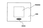
- FIG. 4A in order to observe the digestive tract having a depth, the distance to the corresponding subject largely differs depending on the position on the acquired image. Therefore, for example, as shown in FIG. 5, if AF is performed with the central part of the image as the evaluation area, as shown in FIG. 4A, the subject at a relatively long distance corresponding to the central part of the image will be in focus. If there is a lesion that the user wants to observe at a relatively short distance, the lesion will not be in focus and it will interfere with the user's observation.
- the subject when performing AF with the peripheral part of the image as the evaluation area, the subject is at a relatively short distance corresponding to the peripheral part of the image, so if there is a lesion at a long distance, the lesion is in focus It interferes with the user's observation. Furthermore, it is difficult to determine from the acquired image the position on the image of the lesion site that the user wants to observe, so it is difficult to focus the area that the user wants to observe even when using AF. there were.
- a focus control apparatus capable of executing autofocus in an appropriate state by setting a focus mode of an imaging optical system.
- One aspect of the present invention performs focus control of an imaging optical system including at least a zoom lens for adjusting optical magnification, and performs focus control of focus mode of the imaging optical system, and the imaging optical system
- An image acquisition unit for acquiring an image the focus mode has a fixed focus mode and an AF (Auto-Focus) mode, and the focus control unit is a reference located between the wide angle end and the telephoto end.
- the present invention relates to a focus control device that performs switching control of the fixed focus mode and the AF mode depending on whether the position of the zoom lens is on the wide angle side or the telephoto side with respect to a point.
- switching control between the fixed focus mode and the AF mode is performed based on the positional relationship between the zoom lens and the reference point. This makes it possible to shift to the AF mode in an appropriate state, execute AF, and the like.
- a focus control unit for performing focus control of an imaging optical system including at least a zoom lens for adjusting an optical magnification and performing setting control of a focus mode of the imaging optical system;
- An image acquisition unit for acquiring an image through the focus control unit, and the focus control unit is configured to set the position of the zoom lens to a wide-angle side with respect to a reference point located between the wide-angle end and the telephoto end;
- the present invention relates to a focus control device that stops the continuous AF when the focus mode is set to the mode in which the continuous AF is performed and the position of the zoom lens is on the telephoto side with respect to the reference point.
- an imaging optical system including at least a zoom lens for adjusting an optical magnification, an imaging element for generating an image corresponding to a subject image formed by the imaging optical system, and the imaging optical system.
- a focus control unit that performs focus control of the system and performs control of setting of a focus mode of the imaging optical system, the focus mode has a fixed focus mode and an AF (Auto-Focus) mode, and the focus
- the control unit switches between the fixed focus mode and the AF mode according to whether the position of the zoom lens is on the wide-angle side or the telephoto side with respect to a reference point located between the wide-angle end and the telephoto end. It relates to an endoscope apparatus that performs control.
- Still another aspect of the present invention is a focus control method in an imaging optical system including at least a zoom lens for adjusting an optical magnification, wherein a focusing mode of the imaging optical system is a fixed focus mode and an AF (Auto-Focus).
- a focusing mode of the imaging optical system is a fixed focus mode and an AF (Auto-Focus).
- AF Auto-Focus
- the present invention relates to a focus control method that performs switching control of the fixed focus mode and the AF mode, and performs focus control of the imaging optical system based on the set focus mode.
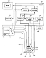
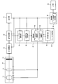
- FIG. 1 is a system configuration example of an endoscope apparatus according to the present embodiment.
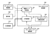
- FIG. 2 is a configuration example of a focus lens control unit.
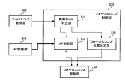
- FIG. 3 shows another configuration example of the focus lens control unit.
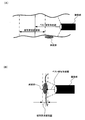
- FIG. 4A is a relationship diagram of the imaging unit and the subject when the zoom lens is on the wide angle side
- FIG. 4B is a relationship diagram of the imaging unit and the subject when the zoom lens is on the telephoto side.
- FIG. 5 illustrates that AF is not effective depending on the setting of the evaluation area.
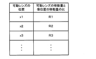
- FIG. 6A is a diagram showing the relationship between the zoom lens position and the depth of field in the fixed focus mode
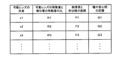
- FIG. 6B is a diagram showing the relationship between the zoom lens position in the AF mode and the depth of field.
- FIG. 6A is a diagram showing the relationship between the zoom lens position and the AF mode and the depth of field.
- FIG. 7 shows an example of the configuration of the operation unit.
- FIG. 8 shows another configuration example of the operation unit.
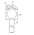
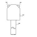
- FIG. 9 is a configuration example of an objective lens system (imaging optical system).
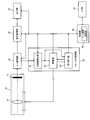
- FIG. 10 shows another system configuration example of the endoscope apparatus according to the present embodiment.
- FIG. 11 is a system configuration example of the endoscope apparatus in the fourth embodiment.
- FIG. 12 is an explanatory diagram of mode switching control.
- FIG. 13 is a system configuration example of the endoscope apparatus in 5th Embodiment.
- FIG. 14 is a system configuration example of an endoscope apparatus according to a sixth embodiment.
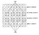
- FIG. 15 is a structural example of the image pick-up element in which the element for phase difference detection was provided.
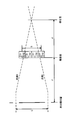
- FIG. 16 is an operation explanatory view of phase difference AF.
- FIG. 17 shows a first example of a look-up table used for phase difference AF.
- FIG. 18 shows a second example of the look-up table used for phase difference AF.
- the endoscope system according to the present embodiment includes a light source unit 100, an imaging unit 200, a processing unit 300, a display unit 400, an external I / F unit 500, and an operation unit 600.
- the light source unit 100 includes a white light source 110 generating white light and a condenser lens 120 for condensing the white light on the light guide fiber 210.
- the imaging unit 200 is formed to be elongated and bendable, for example, to allow insertion into a body cavity.
- the imaging unit 200 includes a light guide fiber 210 for guiding light condensed by the light source unit, and an illumination lens 220 for diffusing the light guided to the tip by the light guide fiber and irradiating the observation target with the light.
- An objective lens system 230 for forming an image of reflected light returning from the observation target, a zoom lens 240 included in the objective lens system 230 for adjusting the optical magnification, and a focus lens 250 included in the objective lens system 230 for adjusting a focal position.
- the zoom lens drive unit 260 and the focus lens drive unit 270 are, for example, voice coil motors (hereinafter, VCMs).
- the imaging device 280 is an imaging device having, for example, a Bayer-arranged color filter.
- the processing unit 300 includes an AD conversion unit 310, a zoom lens control unit 320, a focus lens control unit 330 (focus control unit in a broad sense), an image processing unit 340, and a control unit 350.
- the AD conversion unit 310 converts an analog signal output from the imaging element 280 into a digital image signal, and outputs the digital image signal to the focus lens control unit 330 and the image processing unit 340.
- the zoom lens control unit 320 is connected to the operation unit 600, the zoom lens drive unit 260, and the focus lens control unit 330, and controls the zoom lens position according to the information output from the operation unit 600. Furthermore, the zoom lens control unit 320 outputs the position information of the zoom lens to the focus lens control unit 330.
- the focus lens control unit 330 is connected to the operation unit 600, the focus lens drive unit 270, and the zoom lens control unit 320, and is output from the information output from the operation unit 600 or the zoom lens control unit 320.
- the focus lens position is controlled according to the zoom lens position information.
- the focus lens position and the zoom lens position are defined as the positions of the tips of the focus lens and the zoom lens with reference to the tip of the objective lens system 230, for example, as shown in FIG. Details of the operation unit 600, the zoom lens control unit 320, and the focus lens control unit 330 will be described later.
- the image processing unit 340 performs image processing such as white balance, interpolation processing (demosaicing processing), color conversion, gradation conversion, noise reduction, and the like on the image signal output from the AD conversion unit 310. Output an image signal.
- the display unit 400 is, for example, a liquid crystal monitor, and displays an image signal output from the image processing unit 340.
- the control unit 350 is bi-directionally connected to the white light source 110, the image processing unit 340, and the external I / F unit 500, and controls these in accordance with input information from the external I / F unit 500.
- the external I / F unit 500 is an interface for performing input from the user to the endoscope apparatus, etc., and an exposure amount adjustment for adjusting the brightness of the start button and image for performing start / end of photographing It is configured to include a button, an adjustment button for adjusting various other photographing conditions and parameters of image processing, and the like.
- the operation unit 600 is configured integrally with, for example, the imaging unit 200, and includes a zoom lever 610 and an AF button 620.
- the zoom lever 610 can operate, for example, continuously over a certain range, and the user can adjust the zoom lens position continuously from the WIDE end to the TELE end by moving the zoom lever 610.
- the operation unit 600 outputs the position information of the zoom lever 610 to the zoom lens control unit 320.
- the zoom lens control unit 320 associates the position information of the zoom lever 610 with the position information of the zoom lens using a preset look-up table or the like, and outputs the position information of the zoom lens to the zoom lens drive unit 260.
- the zoom lens drive unit 260 drives the zoom lens 240 based on the position information of the zoom lens output from the zoom lens control unit 320.
- the zoom lens control unit 320 outputs the position information of the zoom lens to the focus lens control unit 330.
- the operation unit 600 alternately outputs an AF start / end signal to the focus lens control unit 330 each time the AF button 620 is pressed, for example.
- FIG. 2 shows an example of the focus lens control unit 330 in the present embodiment.
- the focus lens control unit 330 (focus control unit in a broad sense) includes an observation mode determination unit 331, a focus lens position determination unit 332, and an AF control unit 333.
- the observation mode determination unit 331 determines the observation mode (focus mode) based on the position information of the zoom lens output from the zoom lens control unit 320 and the AF start / end information output from the operation unit 600. Specifically, when the position of the zoom lens is positioned on the WIDE side relative to the predetermined position D, the observation mode determination unit 331 selects the fixed focus mode, and outputs position information of the zoom lens to the focus lens position determination unit 332. Do.
- the observation mode determination unit 331 also selects the fixed focus mode even when the position of the zoom lens is on the TELE side of the predetermined position D and the AF start signal is not output from the operation unit 600, and the zoom lens is selected.
- the position information of is output to the focus lens position determination unit 332.
- the focus lens position determination unit 332 determines the focus lens position based on the position information of the zoom lens, and outputs the position information of the focus lens to the focus lens drive unit 270.
- the focus lens drive unit 270 drives the focus lens 250 based on the position information of the focus lens output from the focus lens position determination unit 332.
- the observation mode determination unit 331 selects the AF mode, and the AF start signal is output. Output to the AF control unit 333. Furthermore, when the zoom lens position is on the TELE side relative to the predetermined position D and the AF end signal is output from the operation unit 600, the observation mode determination unit 331 outputs the AF end signal to the AF control unit 333. .
- the AF control unit 333 starts an AF operation according to the AF start signal output from the observation mode determination unit 331.
- the AF control unit 333 may calculate, for example, the contrast value from the image signal output from the AD conversion unit 310, and drive the focus lens based on a known contrast AF technique. Further, the AF control unit 333 determines whether or not the in-focus state is obtained from the calculated contrast value, and when it is determined that the in-focus state is obtained, the AF operation may be ended. The focus lens may be driven based on a known continuous AF technique so as to continue the AF until the AF end signal is output. Further, in the present embodiment, for example, the image sensor 280 may be provided with a sensor (not shown) for acquiring phase difference information.
- the AD conversion unit 310 generates digital phase difference information from the analog signal output from the imaging device 280 and outputs the digital phase difference information to the AF control unit 333, and the AF control unit 333 is publicly known based on this phase difference information.
- the focus lens may be driven using a phase difference AF technique.
- FIG. 6A is a diagram showing the zoom lens position, the best subject distance corresponding thereto, and the depth of field range when the fixed focus mode is selected in the present embodiment.
- the focus lens position determination unit 332 moves the zoom lens position from the WIDE end to the TELE end as shown in FIG. 6A based on the zoom lens position information output from the observation mode determination unit 331. Then, the focus lens position is determined so that the best subject distance becomes shorter.
- the focus lens position determination unit 332 may determine the focus lens position from the zoom lens position using, for example, a look-up table or the like that associates the preset zoom lens position with the focus lens position.
- FIG. 1 An example of the objective lens system 230 in this embodiment is shown in FIG.
- the focus lens position determination unit 332 always fixes the focus lens position at the reference position regardless of the zoom lens position, thereby obtaining the best subject distance as shown in FIG. And a depth of field range can be realized.
- the best subject distance is designed to be substantially constant even when the angle of view is adjusted according to the zoom lens position.
- the focus lens position determination unit 332 adjusts the focus lens position so that the best subject distance becomes shorter as the zoom lens position moves from the WIDE end to the TELE end. It is possible to realize the best subject distance and the depth of field range as shown in FIG.
- the operation of the user in the case of performing normal observation and magnified observation in the present embodiment will be described with reference to FIGS. 6 (A) and 6 (B).
- the user moves the zoom lever 610 to the WIDE end to perform normal observation for finding a lesion (zoom lens position A in FIG. 6A).
- the imaging unit 200 can acquire an image with a wide angle of view and a wide depth of field.
- the depth of field range at this time is about 10 to 50 mm as shown in FIG. 6 (A).
- the user enlarges the lesion while gradually bringing the imaging unit 200 closer to the found lesion.
- the distance to the lesioned part is 10 mm or less (including the value thereof)
- the lesioned part deviates from the depth of field and begins to blur.
- the user moves the zoom lever 610 to the TELE side to bring the depth of field range closer to the imaging unit (zoom lens positions B to C in FIG. 6A). This allows the user to continue observing the lesion since the lesion is within the depth of field.
- the lesion may be adjusted to be within the depth of field.
- the depth of field range is about 4 to 7 mm, and a certain depth of field is maintained.
- the user often observes in a state where the imaging unit 200 is tilted in parallel or at a slight angle with respect to the wall surface of the digestive tract which is the subject.
- the distance to the corresponding subject largely differs depending on the position on the image acquired as described above.
- the observation mode determination unit 331 selects the fixed focus mode, and the user can easily operate the position of the zoom lever 610 or the imaging unit 200. It is possible to focus on the lesion.
- the user moves the zoom lever 610 to the TELE side while further bringing the imaging unit 200 closer to the lesioned part to further enlarge the lesioned part.
- the depth of field when the fixed focus mode is selected is about 1 mm or less. It becomes.
- the user often performs observation in a state in which the imaging unit 200 substantially faces the wall of the digestive tract that is the subject. This is because if the width of the depth of field is narrow and the imaging unit 200 does not face the subject directly, the region in the image in which the image is in focus becomes narrow.
- the user presses the AF button 620 to start AF.
- the focus lens position is controlled according to the distance to the subject as shown in FIG. 6B, and the user easily focuses on the subject. It becomes possible.
- control is performed such that the AF operates in the range from the zoom lens position D to the TELE end (zoom lens position F).
- the zoom lens position D may be set as the TELE end if the optical magnification when moving the focus lens position is the shortest for the best subject distance is sufficient for magnified observation.
- the observation mode determination unit 331 selects the AF mode, and the AF start / end signal is AF It may be output to the control unit 333.
- the focus position control device controls the position of the focus lens 250 and the setting control of the focus mode of the imaging optical system, and And an image acquisition unit (corresponding to, for example, an AD conversion unit 310) that acquires an image via an imaging optical system.
- the imaging optical system includes a zoom lens 240 that adjusts the optical magnification, and a focus lens 250 that adjusts the focal position.
- the focus mode has a fixed focus mode and an AF (Auto-Focus) mode.
- the focus lens control unit 330 determines that the position of the zoom lens 240 is positioned on the wide-angle side with respect to the reference point
- the switching control of the fixed focus mode and the AF mode is performed depending on whether it is positioned on the side.
- the fixed focus mode is a mode in which when the position of the zoom lens 240 is determined, the position of the focus lens 250 is set to a position determined according to the zoom lens position.
- the best subject distance focused subject distance, which will be described later in detail
- the focus lens position is determined according to the zoom lens position.
- the AF mode is a mode in which autofocus is performed.
- the method of auto focus uses a known method, and may be, for example, contrast AF or phase difference AF.
- the AF mode is, for example, the mode shown in FIG. 6B, and particularly corresponds to the case where the zoom lens position is D to F. As shown in FIG. 6B, even if the zoom lens position is determined in the AF mode, the best subject distance at that time is not uniquely determined.
- the best subject distance is set such that the focus is on the evaluation area (the area for which the contrast value is to be calculated) set in the acquired image.
- the setting of the best subject distance is performed by adjusting the position of the focus lens 250.
- the focal position is the position of the subject with respect to the tip of the objective lens when the image position of the subject coincides with the imaging surface of the imaging device.
- the subject is in focus in a plane on the subject side (in-focus object plane) corresponding to the image plane, and the focal position is represented by, for example, the distance from the tip of the objective lens to the in-focus object plane.
- the focal position in the present specification is a term different from so-called "focus” which is a convergence point of parallel light incident on a lens, and "focal distance” which is a distance from the lens to the "focus".
- the focus position is adjusted by adjusting the position of the focus lens in the lens two-group drive or the position of the zoom lens in the lens group drive.
- the switching control is control for switching between the fixed focus mode and the AF mode based on at least the positional relationship between the zoom lens 240 and the reference point.
- the zoom lens 240 is at the wide angle side, the fixed focus mode is set, and when the zoom lens 240 is at the telephoto side, the AF lens is set to the reference. It may be control of switching based on the positional relationship with the point.
- the fixed focus mode is set when the zoom lens 240 is at the wide angle side, and the fixed focus mode and the AF mode can be switched when the zoom lens 240 is at the telephoto side (for example, the presence or absence of an AF start signal
- switching control may be performed in consideration of other conditions (for example, an AF start signal).
- an AF start signal for example, an AF start signal
- the focus lens control unit 330 causes the in-focus object distance to monotonously decrease.
- the position of the focus lens may be determined.
- the in-focus object distance is the distance from the imaging optical system to the object when the object image formed by the light formed through the imaging optical system in the imaging element 280 is in focus. It is. However, even if the light does not converge at one point on the imaging device 280, the in-focus object distance can be considered to be in focus if the size is smaller than the permissible circle of confusion, so that the in-focus object distance has a certain width. become.
- the in-focus object distance in the present embodiment may be a value having such a width, but in a narrow sense, it is the best object distance, and the light through the imaging optical system is the best object distance. It is assumed that the distance from the imaging optical system to the subject in the case of convergence to one point on the imaging element 280 is represented.
- the in-focus object distance decreases. That is, the depth of field range is set to a position closer to the imaging optical system (that is, a position closer to the imaging optical system is in focus).
- the tip of the insertion unit imaging unit 200
- the subject it is assumed that the distance between the imaging optical system and the subject becomes smaller as the zoom lens 240 is moved to the telephoto side, so using the optical system as shown in FIG. It has the advantage of being easy to match.
- the optical system used in this embodiment assumes lens two group drive.
- the lens two-group drive is a configuration of an optical system capable of driving both the zoom lens and the focus lens.
- the zoom lens 240 even if the zoom lens position is moved from the wide-angle side to the telephoto side, it is also possible to adopt a configuration in which the best subject distance does not change merely by changing the zoom magnification. Configuration used in a general digital still camera etc.
- the focus lens control unit 330 performs control to move the position of the focus lens 250 so as to reduce the best subject distance.
- the focus lens control unit 330 selects the fixed focus mode in which the focus lens 250 is set to a predetermined position according to the zoom lens position as the focus mode.
- switching control between the fixed focus mode and the AF mode may be performed.
- switching control between the fixed focus mode and the AF mode may be, for example, switching by a user's instruction. That is, it may be set to the conventional fixed focus mode which does not use AF by a user's intention, and may be set to AF mode.
- AF mode is selected, AF is performed, so that focusing can be easily performed, and a conventional observation method can be used by making the fixed focus mode selectable. It is possible to expand the range of choices.
- the focus lens control unit 330 sets the focus mode to the AF mode and the AF start signal is input. If not, the focus mode may be set to the fixed focus mode.
- the AF start signal is a signal instructing start of AF, and is input to the focus lens control unit 330 when, for example, the AF button 620 of the operation unit 600 is pressed.
- the AF processing unit 340 may output an AF start signal to the focus lens control unit 330 according to the determination based on the image processing in the image processing unit 340. The method of By doing this, it is possible to set the focus mode in consideration of not only the positional relationship between the zoom lens 240 and the reference point but also the AF start signal.
- the focus lens control unit 330 may set the focus mode to the fixed focus mode even when the AF start signal is input when the zoom lens 240 is positioned on the wide angle side with respect to the reference point.
- the zoom lens position is on the wide angle side, it is possible to set the fixed focus mode even when the AF start signal is input.
- the case where the zoom lens 240 is positioned on the wide angle side with respect to the reference point is the case of screening or the like in the endoscope apparatus as described above, and it is assumed that AF is not effective. In such a case, transition to the AF mode may interfere with the user's observation, such as focusing on a narrow area of the image. Therefore, when the zoom lens position is on the wide angle side, it is desirable to set the fixed focus mode even when the AF start signal is input.
- the focal position control device may also include a zoom lens control unit 320 that controls the position of the zoom lens 240 as shown in FIG. Then, the zoom lens control unit 320 continuously controls the position of the zoom lens 240.
- This enables continuous control of the zoom lens position.
- This can be realized, for example, by a zoom lever 610 or the like capable of setting a continuous position, as shown in FIG. This makes it possible to finely set the position of the zoom lens 240.
- the focus lens control unit 330 may execute single AF or may execute continuous AF.
- single AF is a mode in which focusing is performed only once. For example, in the case of a digital still camera or the like, focusing is performed when the shutter button is pressed halfway. Since focusing is performed once, if the subject distance changes due to movement of the subject after focusing, focusing can not be achieved.
- the continuous AF is a mode in which focusing is continued, and when the subject moves, focusing is performed again in accordance with the moved subject.
- single AF can be used as the AF mode, and continuous AF can also be used. Whether to use single AF or continuous AF may be determined by the system, or may be determined by the user from the operation unit 600 or the like.
- an imaging optical system including a zoom lens 240 for adjusting the optical magnification and a focus lens 250 for adjusting the focal position, and an object imaged by the imaging optical system
- the endoscope apparatus includes an imaging element 280 that generates an image corresponding to the image, and a focus lens control unit 330 that controls the position of the focus lens 250 and controls the setting of the focus mode of the imaging optical system. .
- the focus lens control unit 330 of the endoscope apparatus sets the focus lens 250 at a predetermined position according to the zoom lens position as the focus mode.
- switching control between the fixed focus mode and the AF mode may be performed.
- FIG. 8 is a view showing an example of the operation unit 600 in the present embodiment.
- the operation unit 600 is configured integrally with, for example, the imaging unit 200, and includes an AF button 620 and a zoom button 630.
- the other configuration is the same as that of the first embodiment.
- the operation unit 600 when the zoom button 630 is pressed, the operation unit 600 outputs zoom lens position information to the zoom lens control unit 320. Specifically, each time the zoom button 630 is pressed, the operation unit 600 sequentially outputs information corresponding to zoom lens positions A, B, C, and D shown in FIG. 6A to the zoom lens control unit, for example. Do.
- the zoom lens control unit 320 outputs the zoom lens position information output from the operation unit 600 to the zoom lens drive unit 260.
- the zoom lens drive unit 260 drives the zoom lens based on the position information of the zoom lens output from the zoom lens control unit 320.
- the zoom lens control unit 320 outputs the position information of the zoom lens to the focus lens control unit 330.
- the operation unit 600 alternately outputs an AF start / end signal to the focus lens control unit 330 each time the AF button 620 is pressed, for example.
- the focus lens control unit 330 performs the observation mode as in the first embodiment, based on the position information of the zoom lens output from the zoom lens control unit 320 and the AF start / end information output from the operation unit 600. And control the focus lens position.
- the zoom button 630 when the user repeatedly presses the zoom button 630, the fixed focus mode is selected in the observation mode determination unit 331, and the best subject distance and the depth of field range also correspond to the zoom lens positions A, B, C, D.
- switching is performed as shown in FIG.
- the user can focus on the subject by pressing the zoom button 630 instead of the zoom lever 610 described in the first embodiment.
- the zoom lens position is at D
- the depth of field narrows, making it difficult for the user to focus on the subject.
- the user starts AF by pressing the AF button 620.
- the AF mode is selected in the observation mode determination unit 331, and the focus lens position is controlled according to the distance to the subject as shown in FIG. 6B, whereby the user can easily focus on the lesion. It becomes possible to match.
- the optical magnification in the case where the best subject distance is shortest by moving the focus lens position is sufficient for magnified observation. If the optical magnification in this case is insufficient for magnified observation, for example, the optical magnification may be increased by switching the zoom lens position in the range of A to E or A to F.
- the zoom lens position B when switching the zoom lens position in the range of A to D, the zoom lens position B is omitted, and the zoom lens positions A, C, and D are switched in order by the user repeatedly pressing the zoom button 630. It may be set. Since the depth of field range is relatively wide near zoom lens positions A to C, even if settings such as zoom lens positions A and C are made such that the depth of field ranges are switched not continuous, the user can By adjusting the position of the imaging unit 200, it is possible to easily focus on the subject.
- the focal position control device includes the zoom lens control unit 320 that controls the position of the zoom lens 240. Then, the zoom lens control unit 320 discretely controls the position of the zoom lens 240.
- the zoom lens control unit 320 is a first zoom lens position which is a position on the wide angle side of the reference point and a second zoom lens position which is a position on the telephoto side of the reference point. Control to select one of these may be performed. Then, the focus lens control unit 330 performs switching control of the fixed focus mode and the AF mode depending on whether the zoom lens 240 is at the first zoom lens position or the second zoom lens position.
- the switching control between the fixed focus mode and the AF mode the fixed focus mode is selected at the first zoom lens position on the wide angle side, and the fixed focus mode and the AF mode are selected at the second zoom lens position on the telephoto side. It is conceivable to make it selectable. By doing this, it is possible to limit the position of the zoom lens to a small number, thereby facilitating the user's operation. In the above example, it is sufficient to consider two switchings between the wide-angle mode (first zoom lens position) not using AF and the telephoto mode (second zoom lens position) capable of using AF. Compared with continuous zoom lens position control and discrete zoom lens position control in which there are many selectable zoom lens positions, the burden on the user is lightened.
- the operation unit 600 of the present embodiment includes, for example, a zoom lever 610, and the AF button 620 is omitted.
- the information output from the operation unit 600 is output to the zoom lens control unit 320 and is not output to the focus lens control unit 330.
- the other configuration is the same as that of the first embodiment.
- the focus lens control unit 330 (focus control unit in a broad sense) includes an observation mode determination unit 331, a focus lens position determination unit 332, and an AF control unit 333.
- the observation mode determination unit 331 determines the observation mode based on the position information of the zoom lens output from the zoom lens control unit 320. Specifically, when the position of the zoom lens is positioned on the WIDE side relative to the predetermined position D, the observation mode determination unit 331 selects the fixed focus mode, and outputs position information of the zoom lens to the focus lens position determination unit 332. Do.
- the focus lens position determination unit 332 determines the focus lens position based on the position information of the zoom lens, and outputs the position information of the focus lens to the focus lens drive unit 270.
- the focus lens drive unit 270 drives the focus lens based on the position information of the focus lens output from the focus lens position determination unit 332.
- the method of determining the focus lens position when the fixed focus mode is selected in the present embodiment is the same as that of the first embodiment.
- the observation mode determination unit 331 selects the AF mode, and outputs an AF start signal to the AF control unit 333.
- the AF control unit 333 starts an AF operation according to the AF start signal output from the observation mode determination unit 331.
- AF is automatically started.
- the user can start AF simply by operating the zoom lever 610 without using the AF button 620, so that observation can be performed comfortably.
- the AF control unit 333 determines whether or not the in-focus state is obtained from the calculated contrast value, and when it is determined that the in-focus state is obtained, the AF operation may be ended.
- the focus lens may be driven based on a known continuous AF technique so as to continue the AF until the AF end signal is output.
- the observation mode determination unit 331 selects the fixed focus mode and the zoom lens is selected.
- the position information of the above may be output to the focus lens position determination unit 332, and the end signal of the continuous AF may be output to the AF control unit 333.
- the user can end the continuous AF by moving the zoom lever 610 to the WIDE side.
- the focus lens control unit 330 sets the focus lens 250 at a predetermined position according to the zoom lens position as the focus mode when the zoom lens 240 is positioned on the wide angle side with respect to the reference point.
- control to select the AF mode is performed.
- the zoom lens position when the zoom lens position is on the telephoto side, it is possible to select the AF mode without using other information such as an AF start signal.
- the zoom lens position When the zoom lens position is on the telephoto side, the depth of field is extremely narrow due to the large zoom magnification and the small best subject distance.
- movement of the subject such as pulsation due to observation of the living body by the endoscope device
- movement of the optical system such as camera shake
- manual focusing is difficult and AF is performed. It is natural to select the AF mode to be used. By doing this, it is possible to execute the AF mode without operating the AF button 620 etc. in FIG. 7, it is possible to provide a system that is highly convenient for the user.
- the focus lens control unit 330 ends the AF mode, and the focus mode is the fixed focus mode. It may be set to
- the focus lens control unit 330 of the endoscope apparatus sets the focus lens 250 at a predetermined position according to the zoom lens position as the focus mode when the zoom lens 240 is positioned on the wide angle side with respect to the reference point.
- control to select the AF mode is performed.
- Patent Document 2 discloses an endoscope apparatus in which a focusing drive unit for driving a focus of an objective optical system is provided in an imaging unit, and AF is performed on a subject.
- Patent Document 2 switching of AF stop / start is controlled by a switch provided in the operation unit. For this reason, in addition to the conventional endoscope operation, the user needs to perform the operation of AF stop / start, which increases the complexity.
- a switch is provided to detect the distance to the subject, perform AF according to the distance, and switch on / off of the AF on the condition that the distance is within a predetermined range for a predetermined time or more.
- the focus mode is automatically set according to the observation state. That is, the mode for performing continuous AF operation is set at the time of magnified observation, and the mode for performing continuous AF operation is not set for performing observation in a wide field of view.
- the distance to the subject being focused does not change, so the user can grasp the sense of distance in focus.
- there is no change in the visual field due to the AF operation and there is no adverse effect on observation. Since the AF operation is performed continuously during magnified observation, it is possible to provide an image in focus on the subject that the user wants to see.
- an endoscope apparatus performing lens group drive and phase difference AF will be described, and in the fifth embodiment, an endoscope performing two lens group drive and contrast AF
- the apparatus will be described, in the present embodiment, the combination of the lens driving method and the AF method is not limited to these.
- FIG. 11 shows a configuration example of the endoscope apparatus in the fourth embodiment which performs switching control between the continuous AF mode and the single AF mode.
- the endoscope apparatus illustrated in FIG. 11 includes an imaging unit 10 (insertion unit), an A / D conversion unit 20, a signal processing unit 30 (image processing unit), a focus control unit 35, an output unit 70 (display unit), and a control unit.
- 80 includes an I / F unit 90 (operation unit, external interface unit).
- the imaging unit 10 includes a zoom lens 12 that adjusts an optical magnification, and an imaging element 14 that captures an image of a subject.
- the focus control unit 35 includes a phase difference calculation unit 40 that calculates a phase difference, a drive unit 50 that drives the zoom lens 12, and a switching unit 60 that switches modes.
- An analog signal obtained by photographing through the zoom lens 12 and the imaging device 14 is converted into a digital signal by the A / D converter 20.
- the A / D converter 20 is connected to the signal processor 30 and the phase difference calculator 40.
- the signal processing unit 30 is connected to the output unit 70.
- the phase difference calculation unit 40 is connected to the drive unit 50.
- the drive unit 50 is connected to a drive mechanism (not shown) which is a mechanism for moving the position of the zoom lens 12.
- the drive unit 50 is bi-directionally connected to the switching unit 60.
- the control unit 80 configured by a microcomputer or the like is bi-directionally connected to the A / D conversion unit 20, the signal processing unit 30, the phase difference calculation unit 40, the drive unit 50, the switching unit 60, and the output unit 70.
- an external I / F unit 90 including, for example, a power switch, an interface for setting variables, and the like is bidirectionally connected to the control unit 80.
- the operation of the endoscope apparatus in the fourth embodiment will be described. Reflected light reflected from the subject is imaged on the imaging device 14 by the zoom lens 12 (an imaging lens group (not shown) including the zoom lens 12).
- the imaging device 14 performs photoelectric conversion of image formation, and outputs an analog signal obtained by the photoelectric conversion to the A / D conversion unit 20.
- the A / D conversion unit 20 converts the input analog signal into a digital signal, and outputs the digital signal to the signal processing unit 30.
- a phase difference detection element for detecting a phase difference between two image formations corresponding to the divided pupils is disposed.
- the image sensor 14 including the phase difference detection element will be described in detail later.
- the A / D conversion unit 20 converts an analog signal acquired by the phase difference detection element into a digital signal, and outputs the digital signal to the phase difference calculation unit 40.
- the phase difference calculation unit 40 calculates a phase difference (phase difference information) based on the digital signal acquired by the phase difference detection element and converted by the A / D conversion unit 20.
- the phase difference calculation unit 40 determines the position of the zoom lens 12 at which the subject is in focus (hereinafter referred to as “focusing lens position” as appropriate) based on the calculated phase difference.
- the drive unit 50 holds current position information indicating which position the zoom lens 12 is currently set to.
- the continuous AF mode which is a mode for performing continuous AF (sequential AF)
- the drive unit 50 information on the focusing lens position sequentially determined by the phase difference calculation unit 40.
- the zoom lens 12 is sequentially moved from the current position to the in-focus lens position based on. That is, when the continuous AF mode is on, the position of the zoom lens 12 is moved each time the in-focus lens position changes, and the object is always in focus.
- the drive unit 50 performs the single AF operation based on the information of the in-focus lens position. That is, instead of sequentially moving the position of the zoom lens 12 each time the in-focus lens position changes, the zoom lens 12 is moved to the in-focus lens position one time each time at a predetermined interval.
- the switching unit 60 switches on / off of the continuous AF mode. That is, the continuous AF mode and the single AF mode are switched. Specifically, the switching unit 60 acquires current position information of the zoom lens 12 from the driving unit 50. As shown in FIG. 12, when the current position of the zoom lens 12 is on the wide angle side of the predetermined position Dw, the switching unit 60 turns off the continuous AF mode. Further, when the current position of the zoom lens 12 is on the telephoto side of the predetermined position Dt, the switching unit 60 turns on the continuous AF mode. Note that Dw and Dt may be the same or different.
- the switching unit 60 transmits the on / off information of the continuous AF mode to the drive unit 50.
- the signal processing unit 30 performs image processing such as gradation conversion processing on the image (digital signal) from the A / D conversion unit 20.
- the output unit 70 stores the image subjected to the image processing by the signal processing unit 30 in a recording medium such as a memory card, for example, or outputs the image to a display device (not shown).
- the user inserts the scope of the endoscope in which the imaging unit 10 is disposed at the tip into a living body and starts diagnosis.
- screening is performed with wide field of view to find a point of interest (for example, a lesion candidate).
- the switching unit 60 sets the continuous AF mode to OFF as an initial setting.
- a signal is acquired by the phase difference detection element of the imaging device 14, the signal is converted into a digital signal by the A / D converter 20, and the phase difference is calculated by the phase difference calculator 40 based on the digital signal.
- the focusing lens position is determined sequentially based on the phase difference.
- the drive unit 50 drives the zoom lens 12 only once each time to the in-focus lens position from the phase difference calculation unit 40 at fixed time intervals.
- the switching unit 60 acquires current position information of the zoom lens 12 from the drive unit 50, and determines mode switching. When the current position is on the wide angle side of the predetermined position Dw, the setting of the continuous AF mode is maintained.
- the drive unit 50 drives the zoom lens 12 to the focusing lens position only once at a constant time interval, the position of the zoom lens 12 is driven to the telephoto side from the predetermined position Dt at a certain point in time because magnified observation is performed. It will be done.
- the switching unit 60 switches on the continuous AF mode to ON, and the continuous AF mode is switched to the drive unit 50. Transmit information that it is on.
- the phase difference calculation unit 40 sequentially determines the in-focus lens position, and the drive unit 50 receives the in-focus lens position transmitted from the phase difference calculation unit 40 since the continuous AF mode is turned on.
- the zoom lens 12 is driven sequentially. That is, the continuous AF operation is performed.
- the drive unit 50 sequentially drives the zoom lens 12 to the in-focus lens position, but when shifting to observation in a wide field of view, the zoom lens 12 is driven to the wide angle side.
- the switching unit 60 determines that the current position of the zoom lens 12 acquired from the drive unit 50 is on the wide angle side of the predetermined position Dw, the continuous AF mode is switched off, and the drive unit 50 performs single AF operation. I do.
- the zoom lens 12 may be moved to a predetermined fixed position Dz (position Dz shown in FIG. 12) at a deep depth.
- Dz position Dz shown in FIG. 12
- the position Dz is a position on the wide-angle side of the predetermined position Dw and the depth of field is wider, when continuous AF is not performed, the subject is in focus. It becomes easy to obtain.
- the focus control device performs focus control of the imaging optical system including at least the zoom lens 12 for adjusting the optical magnification, and setting of the focus mode of the imaging optical system. It includes a focus control unit 35 that performs control, and an image acquisition unit that acquires an image via an imaging optical system.
- the focus control unit 35 performs continuous AF when the position of the zoom lens 12 is on the wide-angle side with respect to the reference point Dw located between the wide-angle end and the telephoto end.
- the continuous AF is stopped.
- the focus control unit 35 sets the focus mode to the mode in which single AF is performed.
- the continuous AF mode can be set in the magnified observation, it is possible to provide the user with an easy-to-see image focused on the subject even in the observation at a high magnification where the depth of field is narrow.
- the single AF mode can be set in normal observation, the focus is maintained for a certain period of time and does not change in a short time. Therefore, the user can easily determine the distance at which the user can focus on the screen.
- the AF operation is performed at regular time intervals, the time and effort required for the user to adjust the focus is reduced, and the burden on the user can be reduced.
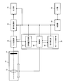
- FIG. 13 shows an example of the configuration of the endoscope apparatus according to the fifth embodiment.
- the endoscope apparatus of FIG. 13 includes an imaging unit 10, an A / D conversion unit 20, a signal processing unit 30, a focus control unit 35, an output unit 70, a control unit 80, and an I / F unit 90.
- the imaging unit 10 includes a focus lens 11 that performs focus adjustment, a zoom lens 12 that adjusts an optical magnification, and an imaging device 14.
- the focus control unit 35 includes a contrast calculation unit 42 that calculates a contrast value, a focusing position determination unit 44 that determines a focusing lens position, a drive unit 50 that drives the focus lens 11 and the zoom lens 12, and a switching unit 60.
- Control unit 80 includes zoom magnification setting unit 82.
- An analog signal captured through the focus lens 11, the zoom lens 12, and the imaging device 14 is converted into a digital signal by the A / D converter 20.
- the A / D conversion unit 20 is connected to the signal processing unit 30.
- the signal processing unit 30 is connected to the contrast calculating unit 42 and the output unit 70.
- the contrast calculation unit 42 is connected to the in-focus position determination unit 44.
- the in-focus position determination unit 44 is connected to the drive unit 50.
- the drive unit 50 is connected to a drive mechanism (not shown) which is a mechanism for moving the position of the focus lens 11 and a drive mechanism (not shown) which is a mechanism for moving the position of the zoom lens 12.
- the drive unit 50 is bi-directionally connected to the switching unit 60.
- control unit 80 configured by a microcomputer or the like includes the A / D conversion unit 20, the signal processing unit 30, the contrast calculation unit 42, the focusing position determination unit 44, the drive unit 50, the switching unit 60, and the output unit 70. And bi-directionally connected.
- an I / F unit 90 including a power switch, an interface for setting variables, and the like is bidirectionally connected to the control unit 80.
- the I / F unit 90 may further be provided with a lever or the like that allows the user to manually operate the position of the zoom lens.
- Reflected light reflected from the subject is imaged on the imaging device 14 by the focus lens 11 and the zoom lens 12 (an imaging lens group (not shown) including the focus lens 11 and the zoom lens 12).
- the image subjected to A / D conversion by the A / D conversion unit 20 is subjected to image processing by the signal processing unit 30, and the image after the image processing is output to the contrast calculation unit 42.
- the drive unit 50 moves the focus lens 11 to a plurality of positions (at least three or more (including its value)) on the optical axis (wobbling), and the signal processing unit 30 acquires an image at each position.
- the contrast calculating unit 42 calculates the contrast value corresponding to each position. That is, the contrast calculation unit 42 performs high-pass filter processing or band pass filter processing on the image from the signal processing unit 30, and integrates the processing result in the image to calculate the contrast value.
- the in-focus position determination unit 44 adjusts the position of the focus lens 11 to focus on the subject based on the plurality of contrast values from the contrast calculation unit 42 and the position of the focus lens 11 corresponding to each contrast value. Determine the lens position). Specifically, the in-focus position determination unit 44 calculates a position at which the contrast value reaches a peak (maximum) from the plurality of contrast values acquired corresponding to the plurality of lens positions, and the position is determined as the in-focus lens Position.
- the drive unit 50 holds current position information indicating which position the zoom lens 12 and the focus lens 11 are currently set to.
- the switching unit 60 switches on / off of the continuous AF mode based on current position information, and the drive unit 50 performs a contrast AF operation or a single AF operation based on the on / off information.
- the switching operation is similar to that of the fourth embodiment.
- the drive unit 50 includes a focus lens control unit 52 that performs control of moving the position of the focus lens 11 and a zoom lens control unit 54 that performs control of moving the position of the zoom lens 12.
- the focus lens control unit 52 drives the focus lens 11 in the above-described AF operation.
- the zoom lens control unit 54 moves the zoom lens 12 to a position corresponding to the optical magnification set by the zoom magnification setting unit 82 of the control unit 80.
- an operation unit for example, the zoom lever 610 in FIG. 7 included in the I / F unit 90, the optical magnification is set in the zoom magnification setting unit 82.
- the continuous AF mode is set to off.
- the focus control unit 35 performs contrast AF once at fixed time intervals. That is, the focus control unit 35 determines the in-focus lens position by the wobbling operation, and performs a series of operations for moving the focus lens 11 to that position once at fixed time intervals.
- the switching unit 60 determines that the position of the focus lens 11 is on the telephoto side of the predetermined position Dt, the switching unit 60 sets the continuous AF mode to on.
- the focus control unit 35 sequentially performs the contrast AF operation. That is, the focus control unit 35 sequentially performs the wobbling operation to determine the in-focus lens position, and moves the focus lens 11 to the in-focus lens position which is sequentially obtained.
- FIG. 14 shows a configuration example of the endoscope apparatus in the sixth embodiment.
- the endoscope apparatus of FIG. 14 includes an imaging unit 10, an A / D conversion unit 20, a signal processing unit 30, a focus control unit 35, an output unit 70, a control unit 80, and an I / F unit 90.
- the imaging unit 10 includes a zoom lens 12 and an imaging element 14.
- the focus control unit 35 includes a phase difference calculation unit 40, a drive unit 50, and a switching unit 60.
- Control unit 80 includes zoom magnification setting unit 82.
- the phase difference calculation unit 40 is connected to the switching unit 60.
- the connection relationship of the other components is the same as in the fourth embodiment.
- the phase difference calculation unit 40 calculates the phase difference based on the signal from the phase difference detection element of the image pickup device 14, and based on the phase difference, the position (focusing lens position) of the zoom lens 12 at which the subject is in focus. calculate.
- the switching unit 60 acquires the current position information of the zoom lens 12 from the drive unit 50, and whether to turn off the continuous AF mode based on the current position information. To judge. In addition, when the continuous AF mode is off, the switching unit 60 obtains the in-focus lens position from the phase difference calculation unit 40, and sets the continuous AF mode on based on the in-focus lens position. Decide whether or not. When the continuous AF mode is off, the zoom lens 12 does not move unless the optical magnification is changed, but by looking at the in-focus lens position, the lens position in focus is on the wide-angle side or on the telephoto side. It is because it can be determined.
- the switching unit 60 determines whether to turn the continuous AF mode off based on the in-focus lens position information from the phase difference calculation unit 40. Good. Further, when the continuous AF mode is off, the switching unit 60 acquires current position information of the zoom lens 12 set according to the optical magnification from the driving unit 50, and based on the current position information, the continuation is continued. It may be determined whether to turn on the as-AF mode. For example, when using the contrast AF, it is considered inappropriate to perform the wobbling operation in the fixed focus mode, so the determination may be made from the current position of the zoom lens 12.
- the drive unit 50 zoom lens to a position (or a predetermined fixed position) corresponding to the optical magnification set by the zoom magnification setting unit 82.
- the user operates an operation unit (for example, the zoom lever 610 in FIG. 7) included in the I / F unit 90, the optical magnification is set in the zoom magnification setting unit 82.
- the operation of the other components is the same as in the fourth embodiment.
- the user inserts the scope of the endoscope in which the imaging unit 10 is disposed at the tip into a living body and starts diagnosis.
- screening is performed with wide field of view to find a point of interest (for example, a lesion candidate).
- the switching unit 60 sets the continuous AF mode to OFF as an initial setting.
- a signal is acquired by the phase difference detection element of the imaging device 14, the signal is converted into a digital signal by the A / D converter 20, and the phase difference is calculated by the phase difference calculator 40 based on the digital signal.
- the focusing lens position is determined sequentially based on the phase difference.
- the switching unit 60 acquires information on the in-focus lens position from the phase difference calculating unit 40, and determines mode switching.
- the continuous AF mode is set to OFF (maintained OFF).
- the fixed focus mode is set, and the zoom lens 12 is set at a fixed position according to the optical magnification.
- the switching unit 60 is the focusing lens position acquired from the phase difference calculating unit 40 (or the current position of the zoom lens 12 acquired from the driving unit 50 when using the current position of the zoom lens 12 according to the optical magnification) Is determined to be on the telephoto side from the predetermined position Dt, the continuous AF mode is switched on, and information that the continuous AF mode is on is transmitted to the drive unit 50.
- the drive unit 50 sequentially drives the zoom lens 12 to the in-focus lens position transmitted from the phase difference calculation unit 40 since the continuous AF mode is turned on. That is, the continuous AF operation is performed.
- the drive unit 50 sequentially drives the zoom lens 12 to the in-focus lens position, but when shifting to observation in a wide field of view, the zoom lens 12 is driven to the wide angle side. If the switching unit 60 determines that the current position of the zoom lens 12 acquired from the drive unit 50 (or the in-focus lens position acquired from the phase difference calculation unit 40) is closer to the wide angle than the predetermined position Dw, continuous operation is performed. The AF mode is switched off, and the drive unit 50 stops the AF operation.
- the zoom lens 12 may be moved to a predetermined fixed position Dz (position Dz shown in FIG. 12) at a deep depth.
- Dz position Dz shown in FIG. 12
- the position Dz is a position on the wide-angle side of the predetermined position Dw and the depth of field is wider, when continuous AF is not performed, the subject is in focus. It becomes easy to obtain.
- the continuous AF mode is set in the magnified observation, even in the case of high magnification observation with a narrow depth of field, it is possible to give the user an easy-to-see image focused on the subject. Can be provided.
- the fixed focus mode is set in normal observation, the focus is not changed unless the user performs an operation, so that it is easy for the user to determine the distance at which the user is in focus in screening or the like.
- the focus control device performs focus control of the imaging optical system including at least the zoom lens for adjusting the optical magnification, and performs focus control of the focus mode of the imaging optical system, and imaging And an image acquisition unit that acquires an image via an optical system.
- the focus mode has a fixed focus mode and an AF (Auto-Focus) mode.
- the focus control unit controls switching between the fixed focus mode and the AF mode according to whether the position of the zoom lens is on the wide-angle side or the telephoto side with respect to a reference point located between the wide-angle end and the telephoto end. Do.
- the focus control unit is, for example, the focus lens control unit 330 (first and second embodiments) of FIG. 1, the focus lens control unit 330 of FIG. 10 (third embodiment), or the focus control of FIG. It corresponds to the part 35 (sixth embodiment).
- focus control may be lens two-group driving or lens group driving.
- AF mode as described in the first embodiment and the like, single AF may be performed or continuous AF may be performed.
- the position of the zoom lens refers to the position at which the zoom lens is actually set in the imaging optical system, or the lens position at which the object is focused in lens group drive for focusing by movement of the zoom lens (focusing It is a position calculated as lens position).
- the user operates the zoom lever 610 in FIG. 7 and the zoom lens control unit 320 in FIG. 1 moves the zoom lens 240 based on the operation information.
- the focus lens control unit 330 determines mode switching based on the position of the zoom lens 240 set to.
- the phase difference calculation unit 40 calculates the in-focus lens position based on the phase difference, and in the continuous AF mode based on the in-focus lens position. It is determined whether or not to switch.
- the fixed focus mode may be set when the zoom lens is at the wide angle side, and the AF mode may be set when the zoom lens is at the telephoto side.
- the fixed focus mode is set when the zoom lens is at the wide angle side, and when the zoom lens is at the telephoto side, still another condition (for example, AF start signal) is taken into consideration.
- the mode and the AF mode may be switched. This makes it possible to perform AF in an appropriate state instead of always performing AF.
- AF is not performed on a tubular empty subject having a thin effect of AF, as shown in FIG. 4 (B). It is possible to execute AF in a state where AF is effective.
- the focus control unit sets the in-focus object distance to a predetermined distance according to the position of the zoom lens in the fixed focus mode.
- the position of the zoom lens and the in-focus object distance such that the in-focus object distance becomes shorter as the zoom lens moves from the position A at the wide angle end to the position F at the telephoto end.
- the lens two-group drive when the zoom lens position is set, the focus lens is moved accordingly, and a predetermined in-focus object distance is realized.
- the in-focus object distance is adjusted by the movement of the zoom lens, and therefore, when the position of the zoom lens is moved, a predetermined in-focus object distance is set accordingly.
- the focus control unit 35 performs AF control based on the phase difference in the AF mode.
- the imaging optical system further includes a phase difference detection element for detecting a phase difference.
- the focus control unit 35 has a phase difference calculation unit 40 that calculates the phase difference based on the signal from the phase difference detection element.
- the focus control unit 35 performs control to focus the subject image based on the calculated phase difference.
- the phase difference detection element is provided in the imaging element 14 as described in FIG. Then, the phase difference calculation unit 40 calculates the in-focus lens position based on the phase difference, and the drive unit 50 moves the zoom lens 12 to the in-focus lens position to perform focus control.
- phase difference AF can be performed in the AF mode.
- the in-focus lens position can be calculated only by detecting the phase difference, it is possible to realize an AF operation generally faster than the contrast AF in which the lens needs to be moved.
- the focus control unit 35 sets the zoom lens 12 at the predetermined position Dz on the wide-angle side when ending the AF mode.
- the depth of field can be set to a wide state when the AF mode is ended. That is, since the fixed focus mode is not performed when the AF mode is ended and the AF is not performed, it is expected that the focus is easily lost and the user is inconvenient if the depth of field remains narrow.
- the zoom lens 12 by setting the zoom lens 12 at the predetermined position Dz on the wide-angle side, the depth of field automatically widens, and the convenience of the user is improved.
- phase difference AF An image sensor 14 provided with a phase difference detection element and a phase difference AF method using the image sensor 14 will be described.
- the phase difference AF performed by the present embodiment is not limited to the method described below.
- various phase difference AF methods such as a method of performing pupil division with a spectacle lens can be adopted.
- FIG. 15 shows a configuration example of an imaging device provided with a phase difference detection element.
- the imaging device shown in FIG. 15 includes normal pixels R, G and B having color filters of Bayer arrangement, and a group of phase sensors S1 and S2 (elements for detecting phase difference) provided in a part of the pixels. Including.
- the pixels S1 and S2 constituting the phase sensors S1 and S2 are, for example, functional pixels described as S1 and S2 in paragraphs [0074] to [0083] of JP-A-2000-156823, each of which is a pixel It has an opening that is offset from the center to the left and right.
- image signals from the S1 group and a plurality of image signals from the S2 group arranged in the horizontal direction in FIG. It can be regarded as the phase signal of the ray that passed through.
- phase signal from the S1 group and the phase signal from the S2 group coincide, and the image
- a phase difference occurs between the phase signal from the S1 group and the phase signal from the S2 group.
- only one set of phase sensors S1 and S2 may be installed, for example, at the center of the imaging unit, or a plurality of sets may be installed at any place of the imaging unit as necessary.
- the movable lens is the zoom lens 12 in lens group drive or the focus lens 11 in lens two group drive.
- FIG. 16 is a diagram showing a ray passing through the divided pupil when the image position is located behind the imaging plane.
- a ray 1 is a ray passing through a pupil corresponding to the S1 group
- a ray 2 is a ray passing through a pupil corresponding to the S2 group.
- S is a vector having positive and negative values, and the direction indicated by the arrow in FIG. 16 is positive.
- phase difference AF is just to use the technique of well-known phase difference AF for calculation of the phase difference S.
- the defocus amount d can be calculated using the following equation (2) obtained by modifying this.
- the defocus amount d may be calculated by the method described in paragraphs [0108] to [0110] of the aforementioned Japanese Patent Application Laid-Open No. 2000-156823.
- G / (F + d) S / d (1)
- d F ⁇ S / (G ⁇ S) (2)
- the phase difference calculation unit 40 in the present embodiment calculates the defocus amount d calculated by the above equation (2) for the phase signals sequentially output from the phase difference sensors S1 and S2 at the same cycle as the image signal.
- the moving amount of the movable lens necessary to realize the in-focus state is calculated, and the calculated moving amount is sequentially output to the drive unit 50.
- the phase difference calculation unit 40 calculates the in-focus lens position from the moving amount of the movable lens and the current position information of the movable lens, and calculates the information of the calculated in-focus lens position as the drive unit 50 (or the switching unit 60 in FIG. 14). May be output sequentially.
- the ratio R of the movement amount of the movable lens to the movement amount of the image position is previously calculated from design data of the imaging optical system by the following equation (3), and The amount D may be calculated.
- R moving amount of movable lens / moving amount of image position (3)
- D -R ⁇ d (4)
- the position xn (n is a natural number) of the movable lens and the corresponding value of Rn Is previously created as a LUT (look-up table) as shown in FIG. 17, and Rn corresponding to the position xn of the movable lens at the timing when the phase signal is output from the phase sensors S1 and S2 is
- the movement amount D can be calculated by using it as R).
- the distance F between the imaging surface and the exit pupil shown in FIG. 16 and the distance G between the centers of gravity of the pupils change depending on the position x of the movable lens as shown in FIG. A LUT to which the values of Fn and Gn to be added are added is created in advance. Then, first, the values of Fn and Gn corresponding to the position xn of the movable lens at the timing when the phase signal is output from the phase sensors S1 and S2 are used as F and G in the above equation (2) for defocusing Calculate the quantity dn. Thereafter, the movement amount D can be calculated by using the calculated dn and Rn corresponding to the position xn of the movable lens as d and R in the above equation (4).
- the phase difference calculation unit 40 may calculate and output the movement amount for all of the phase signals sequentially output from, for example, the phase sensors S1 and S2.
- the movement amount may be calculated and output after sampling. In the latter case, the movement amount is output from the phase difference calculating unit 40 at a cycle longer than that of outputting the image signal.
Landscapes
- Physics & Mathematics (AREA)
- Engineering & Computer Science (AREA)
- Health & Medical Sciences (AREA)
- Life Sciences & Earth Sciences (AREA)
- Optics & Photonics (AREA)
- Multimedia (AREA)
- Signal Processing (AREA)
- Surgery (AREA)
- General Physics & Mathematics (AREA)
- Biophysics (AREA)
- General Health & Medical Sciences (AREA)
- Radiology & Medical Imaging (AREA)
- Nuclear Medicine, Radiotherapy & Molecular Imaging (AREA)
- Biomedical Technology (AREA)
- Heart & Thoracic Surgery (AREA)
- Medical Informatics (AREA)
- Molecular Biology (AREA)
- Animal Behavior & Ethology (AREA)
- Pathology (AREA)
- Public Health (AREA)
- Veterinary Medicine (AREA)
- Astronomy & Astrophysics (AREA)
- General Engineering & Computer Science (AREA)
- Spectroscopy & Molecular Physics (AREA)
- Endoscopes (AREA)
- Instruments For Viewing The Inside Of Hollow Bodies (AREA)
- Studio Devices (AREA)
- Automatic Focus Adjustment (AREA)
- Lens Barrels (AREA)
Abstract
Provided are a focus control device, an endoscope device, and a focus control method, wherein it is possible to perform autofocus in an appropriate state by setting the focus mode of an imaging optical system. A focus control device contains: a focus control unit (330) which controls the focus of an imaging optical system having at least a zoom lens (240) for adjusting the optical magnification and which controls the setting of the focus mode of the imaging optical system; and an image acquisition unit for acquiring an image via the imaging optical system. The focus control device is characterized in that the focus mode has a fixed focus mode and an auto-focus (AF) mode, and the focus control unit (330) switches between the fixed focus mode and the AF mode depending on whether the position of the zoom lens (240) is in the wide-angle side or the telescopic side in relation to a reference point located between the wide-angle side and the telescopic side.
Description
本発明は、フォーカス制御装置、内視鏡装置及びフォーカス制御方法等に関する。
The present invention relates to a focus control apparatus, an endoscope apparatus, a focus control method, and the like.
従来、ズームレンズにより対物レンズの画角及び光学倍率を調整し、広角(以下、WIDE)側では被写体となる消化管全体の観察(通常観察)を行い、望遠(以下、TELE)側では消化管の一部を拡大して観察(拡大観察)を行うズーム機能を備えた内視鏡装置が実用化されている。
Conventionally, the angle of view and optical power of the objective lens are adjusted by a zoom lens, and the entire digestive tract as a subject is observed (normal observation) on the wide-angle (WIDE) side, and the digestive tract is on the tele (hereinafter TELE) side. An endoscope apparatus provided with a zoom function for performing observation (magnification observation) by enlarging a part of the lens is put to practical use.
ズーム機能を備えた内視鏡装置では、TELE側で対物レンズの画角を狭くして光学倍率を大きくすると共に、ベスト被写体距離が短くなるようにレンズ設計を行うことで、拡大観察に必要な光学倍率を実現している場合が多い。ここでベスト被写体距離とは、被写体の像位置が撮像素子の撮像面に一致する場合の、対物レンズ先端から被写体までの距離である。TELE側でベスト被写体距離を短くすることで、被写体により近接して観察を行うことが可能になるため、拡大観察時の光学倍率をより大きくすることが可能になる。
In an endoscope apparatus equipped with a zoom function, the field angle of the objective lens is narrowed on the TELE side to increase the optical magnification, and the lens design is performed so as to shorten the best subject distance, which is necessary for magnified observation. In many cases, optical magnification is realized. Here, the best subject distance is the distance from the tip of the objective lens to the subject when the image position of the subject coincides with the imaging surface of the imaging device. By shortening the best subject distance on the TELE side, it is possible to perform observation closer to the subject, so it is possible to further increase the optical magnification during magnified observation.
一方、ベスト被写体距離が短くなると、被写体位置の移動による像位置の移動量が大きくなるため、一般的に被写界深度が狭くなる。このため、近年のズーム機能を備えた内視鏡装置では、TELE側の被写界深度の幅が1mm以下(その値を含む)となる場合もあり、ユーザーが被写体にピントを合わせることが難しくなってきている。このような問題を解決するために、例えば特許文献1~3に示すようなオートフォーカス(以下、AF)機能を備えた内視鏡装置が提案されている。
On the other hand, when the best subject distance becomes short, the movement amount of the image position due to the movement of the subject position becomes large, so the depth of field generally becomes narrow. For this reason, in the endoscope apparatus having a zoom function in recent years, the width of the depth of field on the TELE side may be 1 mm or less (including the value thereof), and it is difficult for the user to focus on the subject It has become to. In order to solve such a problem, for example, an endoscope apparatus provided with an autofocus (hereinafter referred to as AF) function as shown in Patent Documents 1 to 3 has been proposed.
例えば特許文献1では、通常観察と拡大観察のどちらの状態においてもAF(Auto-Focus)を行っている。しかし、内視鏡における通常観察では、図4(A)に示すように奥行きのある消化管を観察するため、取得される画像上の位置により、対応する被写体までの距離が大きく異なる。そこで、例えば図5に示すように画像の中心部分を評価領域としてAFを行うと、図4(A)に示すように画像の中心部分に対応する比較的遠い距離の被写体にピントが合ってしまい、比較的近い距離にユーザー観察したい病変部がある場合は、病変部にピントが合わずユーザーの観察に支障をきたす。一方、画像の周辺部分を評価領域としてAFを行う場合は、画像の周辺部分に対応する比較的近い距離の被写体にピントが合うため、遠い距離に病変部がある場合は病変部にピントが合わず、ユーザーの観察に支障をきたす。さらに、ユーザーが観察したい病変部の画像上の位置を、取得された画像から判別することは困難であるため、AFを用いた場合もユーザーが観察したい領域にピントを合わせることが難しいという課題があった。
For example, in Patent Document 1, AF (Auto-Focus) is performed in both states of normal observation and magnified observation. However, in normal observation with an endoscope, as shown in FIG. 4A, in order to observe the digestive tract having a depth, the distance to the corresponding subject largely differs depending on the position on the acquired image. Therefore, for example, as shown in FIG. 5, if AF is performed with the central part of the image as the evaluation area, as shown in FIG. 4A, the subject at a relatively long distance corresponding to the central part of the image will be in focus. If there is a lesion that the user wants to observe at a relatively short distance, the lesion will not be in focus and it will interfere with the user's observation. On the other hand, when performing AF with the peripheral part of the image as the evaluation area, the subject is at a relatively short distance corresponding to the peripheral part of the image, so if there is a lesion at a long distance, the lesion is in focus It interferes with the user's observation. Furthermore, it is difficult to determine from the acquired image the position on the image of the lesion site that the user wants to observe, so it is difficult to focus the area that the user wants to observe even when using AF. there were.
本発明の幾つかの態様によれば、撮像光学系の焦点モードを設定することにより、適切な状態においてオートフォーカスを実行可能なフォーカス制御装置、内視鏡装置及びフォーカス制御方法等を提供することができる。
According to some aspects of the present invention, there are provided a focus control apparatus, an endoscope apparatus, a focus control method, and the like capable of executing autofocus in an appropriate state by setting a focus mode of an imaging optical system. Can.
本発明の一態様は、光学倍率を調整するズームレンズを少なくとも含む撮像光学系のフォーカス制御を行うとともに、前記撮像光学系の焦点モードの設定制御を行うフォーカス制御部と、前記撮像光学系を介して画像を取得する画像取得部と、を含み、前記焦点モードは、固定焦点モード及びAF(Auto-Focus)モードを有し、前記フォーカス制御部は、広角端と望遠端の間に位置する基準点に対して、前記ズームレンズの位置が広角側であるか望遠側であるかに応じて、前記固定焦点モード及び前記AFモードの切り替え制御を行うフォーカス制御装置に関係する。
One aspect of the present invention performs focus control of an imaging optical system including at least a zoom lens for adjusting optical magnification, and performs focus control of focus mode of the imaging optical system, and the imaging optical system An image acquisition unit for acquiring an image, the focus mode has a fixed focus mode and an AF (Auto-Focus) mode, and the focus control unit is a reference located between the wide angle end and the telephoto end. The present invention relates to a focus control device that performs switching control of the fixed focus mode and the AF mode depending on whether the position of the zoom lens is on the wide angle side or the telephoto side with respect to a point.
本発明の一態様では、ズームレンズと基準点との位置関係に基づいて、固定焦点モードとAFモードの切り替え制御を行う。これにより、適切な状態においてAFモードに移行し、AFを実行すること等が可能になる。
In one aspect of the present invention, switching control between the fixed focus mode and the AF mode is performed based on the positional relationship between the zoom lens and the reference point. This makes it possible to shift to the AF mode in an appropriate state, execute AF, and the like.
また本発明の他の態様は、光学倍率を調整するズームレンズを少なくとも含む撮像光学系のフォーカス制御を行うとともに、前記撮像光学系の焦点モードの設定制御を行うフォーカス制御部と、前記撮像光学系を介して画像を取得する画像取得部と、を含み、前記フォーカス制御部は、前記ズームレンズの位置が、広角端と望遠端の間に位置する基準点よりも広角側である場合には、コンティニュアスAFを行うモードに前記焦点モードを設定し、前記ズームレンズの位置が、前記基準点よりも望遠側である場合には、前記コンティニュアスAFを停止するフォーカス制御装置に関係する。
Further, according to another aspect of the present invention, there is provided a focus control unit for performing focus control of an imaging optical system including at least a zoom lens for adjusting an optical magnification and performing setting control of a focus mode of the imaging optical system; An image acquisition unit for acquiring an image through the focus control unit, and the focus control unit is configured to set the position of the zoom lens to a wide-angle side with respect to a reference point located between the wide-angle end and the telephoto end; The present invention relates to a focus control device that stops the continuous AF when the focus mode is set to the mode in which the continuous AF is performed and the position of the zoom lens is on the telephoto side with respect to the reference point.
また本発明の更に他の態様は、光学倍率を調整するズームレンズを少なくとも含む撮像光学系と、前記撮像光学系で結像された被写体像に対応する画像を生成する撮像素子と、前記撮像光学系のフォーカス制御を行うとともに、前記撮像光学系の焦点モードの設定制御を行うフォーカス制御部と、を含み、前記焦点モードは、固定焦点モード及びAF(Auto-Focus)モードを有し、前記フォーカス制御部は、広角端と望遠端の間に位置する基準点に対して、前記ズームレンズの位置が広角側であるか望遠側であるかに応じて、前記固定焦点モード及び前記AFモードの切り替え制御を行う内視鏡装置に関係する。
According to still another aspect of the present invention, there is provided an imaging optical system including at least a zoom lens for adjusting an optical magnification, an imaging element for generating an image corresponding to a subject image formed by the imaging optical system, and the imaging optical system. A focus control unit that performs focus control of the system and performs control of setting of a focus mode of the imaging optical system, the focus mode has a fixed focus mode and an AF (Auto-Focus) mode, and the focus The control unit switches between the fixed focus mode and the AF mode according to whether the position of the zoom lens is on the wide-angle side or the telephoto side with respect to a reference point located between the wide-angle end and the telephoto end. It relates to an endoscope apparatus that performs control.
また本発明の更に他の態様は、光学倍率を調整するズームレンズを少なくとも含む撮像光学系におけるフォーカス制御方法であって、前記撮像光学系の焦点モードが、固定焦点モード及びAF(Auto-Focus)モードを有する場合に、広角端と望遠端の間に位置する基準点に対して、前記ズームレンズの位置が広角側であるか望遠側であるかに応じて、前記焦点モードの設定制御として、前記固定焦点モード及び前記AFモードの切り替え制御を行い、設定された前記焦点モードに基づいて前記撮像光学系のフォーカス制御を行うフォーカス制御方法に関係する。
Still another aspect of the present invention is a focus control method in an imaging optical system including at least a zoom lens for adjusting an optical magnification, wherein a focusing mode of the imaging optical system is a fixed focus mode and an AF (Auto-Focus). As a setting control of the focus mode according to whether the position of the zoom lens is on the wide-angle side or the telephoto side with respect to a reference point located between the wide-angle end and the telephoto end when having a mode. The present invention relates to a focus control method that performs switching control of the fixed focus mode and the AF mode, and performs focus control of the imaging optical system based on the set focus mode.
以下、本実施形態について説明する。なお、以下に説明する本実施形態は、請求の範囲に記載された本発明の内容を不当に限定するものではない。また本実施形態で説明される構成の全てが、本発明の必須構成要件であるとは限らない。
Hereinafter, the present embodiment will be described. Note that the embodiments described below do not unduly limit the contents of the present invention described in the claims. Further, not all of the configurations described in the present embodiment are necessarily essential configuration requirements of the present invention.
1.第1の実施形態
本発明の第1の実施形態に係る内視鏡システムについて、図1を用いて説明する。本実施形態に係る内視鏡システムは、光源部100と、撮像部200と、処理部300と、表示部400と、外部I/F部500と、操作部600を備えている。 1. First Embodiment An endoscope system according to a first embodiment of the present invention will be described with reference to FIG. The endoscope system according to the present embodiment includes alight source unit 100, an imaging unit 200, a processing unit 300, a display unit 400, an external I / F unit 500, and an operation unit 600.
本発明の第1の実施形態に係る内視鏡システムについて、図1を用いて説明する。本実施形態に係る内視鏡システムは、光源部100と、撮像部200と、処理部300と、表示部400と、外部I/F部500と、操作部600を備えている。 1. First Embodiment An endoscope system according to a first embodiment of the present invention will be described with reference to FIG. The endoscope system according to the present embodiment includes a
光源部100は、白色光を発生する白色光源110と白色光をライトガイドファイバ210に集光するための集光レンズ120を備えている。
The light source unit 100 includes a white light source 110 generating white light and a condenser lens 120 for condensing the white light on the light guide fiber 210.
撮像部200は、例えば体腔への挿入を可能にするため細長くかつ湾曲可能に形成されている。撮像部200には、光源部で集光された光を導くためのライトガイドファイバ210と、該ライトガイドファイバにより先端まで導かれてきた光を拡散させて観察対象に照射する照明レンズ220と、観察対象から戻る反射光を結像する対物レンズ系230と、対物レンズ系230に含まれ光学倍率を調整するズームレンズ240と、対物レンズ系230に含まれ焦点位置を調整するフォーカスレンズ250と、ズームレンズ240を駆動するズームレンズ駆動部260と、フォーカスレンズ250を駆動するフォーカスレンズ駆動部270と、結像された反射光を光電変換して画像を生成する撮像素子280を備えている。ズームレンズ駆動部260及びフォーカスレンズ駆動部270は例えばボイスコイルモーター(以下、VCM)である。また、撮像素子280は例えばベイヤ配列の色フィルタを持つ撮像素子である。
The imaging unit 200 is formed to be elongated and bendable, for example, to allow insertion into a body cavity. The imaging unit 200 includes a light guide fiber 210 for guiding light condensed by the light source unit, and an illumination lens 220 for diffusing the light guided to the tip by the light guide fiber and irradiating the observation target with the light. An objective lens system 230 for forming an image of reflected light returning from the observation target, a zoom lens 240 included in the objective lens system 230 for adjusting the optical magnification, and a focus lens 250 included in the objective lens system 230 for adjusting a focal position. A zoom lens drive unit 260 that drives the zoom lens 240, a focus lens drive unit 270 that drives the focus lens 250, and an imaging device 280 that photoelectrically converts the formed reflected light to generate an image. The zoom lens drive unit 260 and the focus lens drive unit 270 are, for example, voice coil motors (hereinafter, VCMs). Further, the imaging device 280 is an imaging device having, for example, a Bayer-arranged color filter.
処理部300はAD変換部310と、ズームレンズ制御部320と、フォーカスレンズ制御部330(広義にはフォーカス制御部)と、画像処理部340と、制御部350を備えている。AD変換部310は、撮像素子280から出力されるアナログ信号をデジタルの画像信号に変換してフォーカスレンズ制御部330と、画像処理部340に出力する。
The processing unit 300 includes an AD conversion unit 310, a zoom lens control unit 320, a focus lens control unit 330 (focus control unit in a broad sense), an image processing unit 340, and a control unit 350. The AD conversion unit 310 converts an analog signal output from the imaging element 280 into a digital image signal, and outputs the digital image signal to the focus lens control unit 330 and the image processing unit 340.
ズームレンズ制御部320は、操作部600と、ズームレンズ駆動部260と、フォーカスレンズ制御部330とに接続されており、操作部600から出力される情報に従ってズームレンズ位置を制御する。さらにズームレンズ制御部320は、ズームレンズの位置情報をフォーカスレンズ制御部330に出力する。フォーカスレンズ制御部330は、操作部600と、フォーカスレンズ駆動部270と、ズームレンズ制御部320とに接続されており、操作部600から出力される情報や、ズームレンズ制御部320から出力されるズームレンズの位置情報に従ってフォーカスレンズ位置を制御する。ここでフォーカスレンズ位置及びズームレンズ位置は、例えば図9に示すように、対物レンズ系230の先端を基準とした場合の、フォーカスレンズ及びズームレンズの先端の位置として定義する。操作部600、ズームレンズ制御部320、フォーカスレンズ制御部330の詳細については後述する。
The zoom lens control unit 320 is connected to the operation unit 600, the zoom lens drive unit 260, and the focus lens control unit 330, and controls the zoom lens position according to the information output from the operation unit 600. Furthermore, the zoom lens control unit 320 outputs the position information of the zoom lens to the focus lens control unit 330. The focus lens control unit 330 is connected to the operation unit 600, the focus lens drive unit 270, and the zoom lens control unit 320, and is output from the information output from the operation unit 600 or the zoom lens control unit 320. The focus lens position is controlled according to the zoom lens position information. Here, the focus lens position and the zoom lens position are defined as the positions of the tips of the focus lens and the zoom lens with reference to the tip of the objective lens system 230, for example, as shown in FIG. Details of the operation unit 600, the zoom lens control unit 320, and the focus lens control unit 330 will be described later.
画像処理部340は、AD変換部310から出力された画像信号に対してホワイトバランス、補間処理(デモザイキング処理)、色変換、階調変換、ノイズリダクション等の画像処理を施し、表示部400に画像信号を出力する。表示部400は例えば液晶モニタであり、画像処理部340から出力される画像信号を表示する。制御部350は、白色光源110、画像処理部340、外部I/F部500と双方向に接続されており、外部I/F部500からの入力情報に従ってこれらを制御する。外部I/F部500は、内視鏡装置に対するユーザーからの入力等を行うためのインターフェースであり、撮影の開始/終了を行うためのスタートボタンや画像の明るさを調整するための露光量調整ボタン、その他の各種撮影条件や画像処理のパラメータを調整するための調整ボタンなどを含んで構成されている。
The image processing unit 340 performs image processing such as white balance, interpolation processing (demosaicing processing), color conversion, gradation conversion, noise reduction, and the like on the image signal output from the AD conversion unit 310. Output an image signal. The display unit 400 is, for example, a liquid crystal monitor, and displays an image signal output from the image processing unit 340. The control unit 350 is bi-directionally connected to the white light source 110, the image processing unit 340, and the external I / F unit 500, and controls these in accordance with input information from the external I / F unit 500. The external I / F unit 500 is an interface for performing input from the user to the endoscope apparatus, etc., and an exposure amount adjustment for adjusting the brightness of the start button and image for performing start / end of photographing It is configured to include a button, an adjustment button for adjusting various other photographing conditions and parameters of image processing, and the like.
次に操作部600、ズームレンズ制御部320、フォーカスレンズ制御部330の詳細について説明する。図7に本実施形態における操作部600の一例を示す。本実施形態において、操作部600は例えば撮像部200と一体化して構成されており、ズームレバー610とAFボタン620を備えている。ズームレバー610は、例えば一定の範囲を連続的に動作させることが可能であり、ユーザーはズームレバー610を動かすことで、ズームレンズ位置をWIDE端からTELE端まで連続的に調整することができる。具体的には、例えば操作部600は、ズームレバー610の位置情報をズームレンズ制御部320に出力する。ズームレンズ制御部320は予め設定されたルックアップテーブル等を用いてズームレバー610の位置情報をズームレンズの位置情報に対応付け、ズームレンズの位置情報をズームレンズ駆動部260に出力する。ズームレンズ駆動部260は、ズームレンズ制御部320から出力されたズームレンズの位置情報に基づいて、ズームレンズ240を駆動する。さらにズームレンズ制御部320は、ズームレンズの位置情報をフォーカスレンズ制御部330に出力する。また、操作部600は例えばAFボタン620が押されるたびに、AFの開始/終了信号を交互にフォーカスレンズ制御部330に出力する。
Next, the details of the operation unit 600, the zoom lens control unit 320, and the focus lens control unit 330 will be described. An example of the operation part 600 in this embodiment is shown in FIG. In the present embodiment, the operation unit 600 is configured integrally with, for example, the imaging unit 200, and includes a zoom lever 610 and an AF button 620. The zoom lever 610 can operate, for example, continuously over a certain range, and the user can adjust the zoom lens position continuously from the WIDE end to the TELE end by moving the zoom lever 610. Specifically, for example, the operation unit 600 outputs the position information of the zoom lever 610 to the zoom lens control unit 320. The zoom lens control unit 320 associates the position information of the zoom lever 610 with the position information of the zoom lens using a preset look-up table or the like, and outputs the position information of the zoom lens to the zoom lens drive unit 260. The zoom lens drive unit 260 drives the zoom lens 240 based on the position information of the zoom lens output from the zoom lens control unit 320. Furthermore, the zoom lens control unit 320 outputs the position information of the zoom lens to the focus lens control unit 330. In addition, the operation unit 600 alternately outputs an AF start / end signal to the focus lens control unit 330 each time the AF button 620 is pressed, for example.
図2に本実施形態におけるフォーカスレンズ制御部330の一例を示す。フォーカスレンズ制御部330(広義にはフォーカス制御部)は、観察モード判定部331と、フォーカスレンズ位置決定部332と、AF制御部333を備えている。観察モード判定部331は、ズームレンズ制御部320から出力されたズームレンズの位置情報と、操作部600から出力されたAFの開始/終了情報に基づいて、観察モード(焦点モード)を決定する。具体的には、観察モード判定部331はズームレンズの位置が所定の位置DよりもWIDE側に位置する場合は固定焦点モードを選択し、ズームレンズの位置情報をフォーカスレンズ位置決定部332に出力する。また、観察モード判定部331は、ズームレンズの位置が所定の位置DよりもTELE側にあり、操作部600からAFの開始信号が出力されていない場合も、固定焦点モードを選択し、ズームレンズの位置情報をフォーカスレンズ位置決定部332に出力する。フォーカスレンズ位置決定部332は、ズームレンズの位置情報に基づいてフォーカスレンズ位置を決定し、フォーカスレンズの位置情報をフォーカスレンズ駆動部270に出力する。フォーカスレンズ駆動部270は、フォーカスレンズ位置決定部332から出力されたフォーカスレンズの位置情報に基づいて、フォーカスレンズ250を駆動する。
FIG. 2 shows an example of the focus lens control unit 330 in the present embodiment. The focus lens control unit 330 (focus control unit in a broad sense) includes an observation mode determination unit 331, a focus lens position determination unit 332, and an AF control unit 333. The observation mode determination unit 331 determines the observation mode (focus mode) based on the position information of the zoom lens output from the zoom lens control unit 320 and the AF start / end information output from the operation unit 600. Specifically, when the position of the zoom lens is positioned on the WIDE side relative to the predetermined position D, the observation mode determination unit 331 selects the fixed focus mode, and outputs position information of the zoom lens to the focus lens position determination unit 332. Do. The observation mode determination unit 331 also selects the fixed focus mode even when the position of the zoom lens is on the TELE side of the predetermined position D and the AF start signal is not output from the operation unit 600, and the zoom lens is selected. The position information of is output to the focus lens position determination unit 332. The focus lens position determination unit 332 determines the focus lens position based on the position information of the zoom lens, and outputs the position information of the focus lens to the focus lens drive unit 270. The focus lens drive unit 270 drives the focus lens 250 based on the position information of the focus lens output from the focus lens position determination unit 332.
また、観察モード判定部331は、ズームレンズ位置が所定の位置DよりもTELE側にあり、操作部600からAFの開始信号が出力された場合は、AFモードを選択し、AFの開始信号をAF制御部333に出力する。さらに観察モード判定部331は、ズームレンズ位置が所定の位置DよりもTELE側にあり、操作部600からAFの終了信号が出力された場合は、AFの終了信号をAF制御部333に出力する。AF制御部333は、観察モード判定部331から出力されたAFの開始信号に従って、AF動作を開始する。ここでAF制御部333は、例えばAD変換部310から出力される画像信号からコントラスト値を算出し、公知のコントラストAF技術に基づいてフォーカスレンズを駆動すればよい。さらにAF制御部333は、算出されたコントラスト値から合焦状態となったか否かの判定を行い、合焦状態と判定された場合はAF動作を終了してもよいし、観察モード判定部331からAFの終了信号が出力されるまではAFを継続するように、公知のコンティニュアスAF技術に基づいて、フォーカスレンズを駆動してもよい。また本実施形態は、例えば撮像素子280に図示しない位相差情報取得用のセンサを備えてもよい。この場合、AD変換部310は撮像素子280から出力されるアナログ信号からデジタルの位相差情報を生成してAF制御部333に出力し、AF制御部333はこの位相差情報に基づいて、公知の位相差AF技術を用いてフォーカスレンズを駆動すればよい。
When the zoom lens position is on the TELE side of the predetermined position D and the AF start signal is output from the operation unit 600, the observation mode determination unit 331 selects the AF mode, and the AF start signal is output. Output to the AF control unit 333. Furthermore, when the zoom lens position is on the TELE side relative to the predetermined position D and the AF end signal is output from the operation unit 600, the observation mode determination unit 331 outputs the AF end signal to the AF control unit 333. . The AF control unit 333 starts an AF operation according to the AF start signal output from the observation mode determination unit 331. Here, the AF control unit 333 may calculate, for example, the contrast value from the image signal output from the AD conversion unit 310, and drive the focus lens based on a known contrast AF technique. Further, the AF control unit 333 determines whether or not the in-focus state is obtained from the calculated contrast value, and when it is determined that the in-focus state is obtained, the AF operation may be ended. The focus lens may be driven based on a known continuous AF technique so as to continue the AF until the AF end signal is output. Further, in the present embodiment, for example, the image sensor 280 may be provided with a sensor (not shown) for acquiring phase difference information. In this case, the AD conversion unit 310 generates digital phase difference information from the analog signal output from the imaging device 280 and outputs the digital phase difference information to the AF control unit 333, and the AF control unit 333 is publicly known based on this phase difference information. The focus lens may be driven using a phase difference AF technique.
次にフォーカスレンズ位置決定部332における、フォーカスレンズ位置の決定方法の詳細について説明する。図6(A)は本実施形態において固定焦点モードが選択されている場合の、ズームレンズ位置とそれに対応するベスト被写体距離、及び被写界深度範囲を示した図である。なお本実施形態では、ズームレバー610を操作することでズームレンズ位置を連続的に移動させることが可能であるが、ここでは説明を分かりやすくするため、ズームレンズ位置を段階的に移動させた場合を示している。本実施形態においてフォーカスレンズ位置決定部332は、観察モード判定部331から出力されるズームレンズの位置情報に基づいて、図6(A)に示すようにズームレンズ位置がWIDE端からTELE端に移動するに従って、ベスト被写体距離が短くなるようにフォーカスレンズ位置を決定する。ここでズームレンズ位置とその時に実現したいベスト被写体距離が決まれば、対物レンズ系230の設計データから、フォーカスレンズ位置は一義的に算出される。このためフォーカスレンズ位置決定部332は、例えば予め設定されたズームレンズ位置とフォーカスレンズ位置を対応付けるルックアップテーブル等を用いて、ズームレンズ位置からフォーカスレンズ位置を決定すればよい。
Next, details of a method of determining the focus lens position in the focus lens position determination unit 332 will be described. FIG. 6A is a diagram showing the zoom lens position, the best subject distance corresponding thereto, and the depth of field range when the fixed focus mode is selected in the present embodiment. In the present embodiment, it is possible to move the zoom lens position continuously by operating the zoom lever 610, but in the case where the zoom lens position is moved stepwise in order to make the explanation easy to understand here. Is shown. In the present embodiment, the focus lens position determination unit 332 moves the zoom lens position from the WIDE end to the TELE end as shown in FIG. 6A based on the zoom lens position information output from the observation mode determination unit 331. Then, the focus lens position is determined so that the best subject distance becomes shorter. Here, if the zoom lens position and the best subject distance to be realized at that time are determined, the focus lens position is uniquely calculated from the design data of the objective lens system 230. Therefore, the focus lens position determination unit 332 may determine the focus lens position from the zoom lens position using, for example, a look-up table or the like that associates the preset zoom lens position with the focus lens position.
図9に本実施形態における対物レンズ系230の一例を示す。この対物レンズ系は、フォーカスレンズ位置を一定の基準位置に固定し、ズームレンズ位置をWIDE端からTELE端に移動させた場合に、画角が狭くなる(光学倍率が大きくなる)と共にベスト被写体距離が短くなるような設計がなされている。このような対物レンズ系を使用する場合、フォーカスレンズ位置決定部332は、ズームレンズ位置によらずフォーカスレンズ位置を常に基準位置に固定することで、図6(A)に示すようなベスト被写体距離及び被写界深度範囲を実現することができる。また、例えば図示しない一般的なデジタルカメラの対物レンズ系では、ズームレンズ位置により画角を調整した場合も、ベスト被写体距離がほぼ一定になるような設計がなされている場合が多い。このような対物レンズ系を使用する場合、フォーカスレンズ位置決定部332は、ズームレンズ位置がWIDE端からTELE端に移動するに従ってベスト被写体距離が短くなるように、フォーカスレンズ位置を調整することで、図6(A)に示すようなベスト被写体距離及び被写界深度範囲を実現することが可能である。
An example of the objective lens system 230 in this embodiment is shown in FIG. In this objective lens system, when the focus lens position is fixed at a fixed reference position and the zoom lens position is moved from the WIDE end to the TELE end, the angle of view becomes narrow (the optical magnification increases) and the best subject distance Is designed to be short. When such an objective lens system is used, the focus lens position determination unit 332 always fixes the focus lens position at the reference position regardless of the zoom lens position, thereby obtaining the best subject distance as shown in FIG. And a depth of field range can be realized. For example, in an objective lens system of a general digital camera (not shown), in many cases, the best subject distance is designed to be substantially constant even when the angle of view is adjusted according to the zoom lens position. When such an objective lens system is used, the focus lens position determination unit 332 adjusts the focus lens position so that the best subject distance becomes shorter as the zoom lens position moves from the WIDE end to the TELE end. It is possible to realize the best subject distance and the depth of field range as shown in FIG.
ここで、本実施形態において通常観察及び拡大観察を行う場合のユーザーの操作について、図6(A)、(B)を用いて説明する。まず、ユーザーはズームレバー610をWIDE端に移動させ、病変部を発見するための通常観察を行う(図6(A)のズームレンズ位置A)。この時、撮像部200では図4(A)に示すように、画角及び被写界深度が広い画像を取得することができる。本実施形態において、この時の被写界深度範囲は図6(A)に示すように約10~50mmである。
Here, the operation of the user in the case of performing normal observation and magnified observation in the present embodiment will be described with reference to FIGS. 6 (A) and 6 (B). First, the user moves the zoom lever 610 to the WIDE end to perform normal observation for finding a lesion (zoom lens position A in FIG. 6A). At this time, as shown in FIG. 4A, the imaging unit 200 can acquire an image with a wide angle of view and a wide depth of field. In the present embodiment, the depth of field range at this time is about 10 to 50 mm as shown in FIG. 6 (A).
次にユーザーは、発見した病変部に対して撮像部200を徐々に近づけながら、病変部を拡大していく。本実施形態では病変部までの距離が10mm以下(その値を含む)になると、病変部が被写界深度から外れてボケはじめる。この時、ユーザーはズームレバー610をTELE側に移動させ、被写界深度範囲を撮像部に近づける(図6(A)ズームレンズ位置B~C)。これにより病変部が被写界深度内に入るため、ユーザーは病変部の観察を継続することができる。ここではズームレバー610と撮像部200の位置の両方をユーザーが操作することで、病変部が被写界深度内に入るように調整を行ってもよい。
Next, the user enlarges the lesion while gradually bringing the imaging unit 200 closer to the found lesion. In the present embodiment, when the distance to the lesioned part is 10 mm or less (including the value thereof), the lesioned part deviates from the depth of field and begins to blur. At this time, the user moves the zoom lever 610 to the TELE side to bring the depth of field range closer to the imaging unit (zoom lens positions B to C in FIG. 6A). This allows the user to continue observing the lesion since the lesion is within the depth of field. Here, when the user operates both the zoom lever 610 and the position of the imaging unit 200, the lesion may be adjusted to be within the depth of field.
本実施形態においては、ズームレンズ位置がCの場合でも被写界深度範囲は約4~7mmであり、ある程度の被写界深度が維持されている。このような条件下では、図4(A)に示したように、ユーザーは被写体となる消化管の壁面に対して撮像部200を平行もしくは少し斜めに傾けた状態で観察する場合が多い。この時、前述したように取得される画像上の位置によって、対応する被写体までの距離が大きく異なる。さらに、ユーザーが観察したいと考えている病変部の画像上の位置を、取得された画像から判別することは困難であるため、AFを行うことで病変部に正確にピントを合わせることは困難である。一方、ここではある程度の被写界深度が維持されているため、観察モード判定部331では固定焦点モードが選択され、ユーザーがズームレバー610や撮像部200の位置を操作することで、ユーザーが容易に病変部にピントを合わせることが可能になる。
In the present embodiment, even when the zoom lens position is C, the depth of field range is about 4 to 7 mm, and a certain depth of field is maintained. Under such conditions, as shown in FIG. 4A, the user often observes in a state where the imaging unit 200 is tilted in parallel or at a slight angle with respect to the wall surface of the digestive tract which is the subject. At this time, the distance to the corresponding subject largely differs depending on the position on the image acquired as described above. Furthermore, since it is difficult to determine from the acquired image the position on the image of the lesion that the user wants to observe, it is difficult to focus the lesion accurately by performing AF. is there. On the other hand, since a certain depth of field is maintained here, the observation mode determination unit 331 selects the fixed focus mode, and the user can easily operate the position of the zoom lever 610 or the imaging unit 200. It is possible to focus on the lesion.
次にユーザーは、撮像部200をさらに病変部に近づけながら、ズームレバー610をTELE側に移動させ、病変部をより拡大する。本実施形態においては、ズームレンズ位置がDよりもTELE側にあると、図6(A)に示すように固定焦点モードが選択されている場合の被写界深度の幅は1mm前後かそれ以下となる。このような条件下では、図4(B)に示すようにユーザーは被写体となる消化管の壁面に対して撮像部200をほぼ正対させた状態で観察を行う場合が多い。これは被写界深度の幅が狭い場合、被写体に対して撮像部200を正対させないと、画像中のピントが合う領域が狭くなるからである。このような場合においては、ユーザーがズームレバー610や撮像部200の位置を操作することで被写体にピントを合わせることが難しくなる。このため、ユーザーはAFボタン620を押してAFを開始する。この時、観察モード判定部331でAFモードが選択されることで、図6(B)に示すように被写体までの距離に合わせてフォーカスレンズ位置が制御され、ユーザーが容易に被写体にピントを合わせることが可能になる。
Next, the user moves the zoom lever 610 to the TELE side while further bringing the imaging unit 200 closer to the lesioned part to further enlarge the lesioned part. In the present embodiment, when the zoom lens position is on the TELE side of D, as shown in FIG. 6A, the depth of field when the fixed focus mode is selected is about 1 mm or less. It becomes. Under such conditions, as shown in FIG. 4B, the user often performs observation in a state in which the imaging unit 200 substantially faces the wall of the digestive tract that is the subject. This is because if the width of the depth of field is narrow and the imaging unit 200 does not face the subject directly, the region in the image in which the image is in focus becomes narrow. In such a case, it is difficult for the user to adjust the focus on the subject by operating the position of the zoom lever 610 or the imaging unit 200. Thus, the user presses the AF button 620 to start AF. At this time, as the AF mode is selected by the observation mode determination unit 331, the focus lens position is controlled according to the distance to the subject as shown in FIG. 6B, and the user easily focuses on the subject. It becomes possible.
また、本実施形態においては、ズームレンズ位置DからTELE端(ズームレンズ位置F)の範囲でAFが動作するように制御を行っている。しかし例えばズームレンズ位置Dにおいて、フォーカスレンズ位置を移動することでベスト被写体距離を最も短くした場合の光学倍率が拡大観察に十分であれば、ズームレンズ位置DをTELE端としてもよい。この場合、観察モード判定部331は、ズームレンズ位置がTELE端にあり、操作部600からAFの開始/終了信号が出力された場合は、AFモードを選択し、AFの開始/終了信号をAF制御部333に出力すればよい。
Further, in the present embodiment, control is performed such that the AF operates in the range from the zoom lens position D to the TELE end (zoom lens position F). However, for example, at the zoom lens position D, the zoom lens position D may be set as the TELE end if the optical magnification when moving the focus lens position is the shortest for the best subject distance is sufficient for magnified observation. In this case, when the zoom lens position is at the TELE end and the AF start / end signal is output from the operation unit 600, the observation mode determination unit 331 selects the AF mode, and the AF start / end signal is AF It may be output to the control unit 333.
以上の本実施形態では、焦点位置制御装置(フォーカス制御装置)は図1に示したように、フォーカスレンズ250の位置制御及び撮像光学系の焦点モードの設定制御を行うフォーカスレンズ制御部330と、撮像光学系を介して画像を取得する画像取得部(例えばAD変換部310に対応)とを含む。撮像光学系は、光学倍率を調整するズームレンズ240と、焦点位置を調整するフォーカスレンズ250とを含む。また、焦点モードは固定焦点モードと、AF(Auto-Focus)モードを有する。そして、ズームレンズ位置の広角端と望遠端の間の位置に基準点を設定した場合に、フォーカスレンズ制御部330は、ズームレンズ240の位置が基準点に対して広角側に位置するか或いは望遠側に位置するかに応じて、固定焦点モードとAFモードの切り替え制御を行う。
In the above embodiment, as shown in FIG. 1, the focus position control device (focus control device) controls the position of the focus lens 250 and the setting control of the focus mode of the imaging optical system, and And an image acquisition unit (corresponding to, for example, an AD conversion unit 310) that acquires an image via an imaging optical system. The imaging optical system includes a zoom lens 240 that adjusts the optical magnification, and a focus lens 250 that adjusts the focal position. Also, the focus mode has a fixed focus mode and an AF (Auto-Focus) mode. When the reference point is set to a position between the wide-angle end and the telephoto end of the zoom lens position, the focus lens control unit 330 determines that the position of the zoom lens 240 is positioned on the wide-angle side with respect to the reference point The switching control of the fixed focus mode and the AF mode is performed depending on whether it is positioned on the side.
ここで、固定焦点モードとは、ズームレンズ240の位置が決定された場合に、当該ズームレンズ位置に応じて決定される位置にフォーカスレンズ250の位置を設定するモードのことである。例えば図6(A)に示したモードであり、ズームレンズ位置が決定されると、その際のベスト被写体距離(合焦被写体距離、詳細については後述)が一意に決定される。フォーカスレンズ250の位置に応じてベスト被写体距離は変化するものであることに鑑みれば、ズームレンズ位置に応じてフォーカスレンズ位置が決定されるということに他ならない。
Here, the fixed focus mode is a mode in which when the position of the zoom lens 240 is determined, the position of the focus lens 250 is set to a position determined according to the zoom lens position. For example, in the mode shown in FIG. 6A, when the zoom lens position is determined, the best subject distance (focused subject distance, which will be described later in detail) at that time is uniquely determined. In view of the fact that the best subject distance changes in accordance with the position of the focus lens 250, the focus lens position is determined according to the zoom lens position.
これに対して、AFモードとは、オートフォーカスが行われるモードのことである。オートフォーカスの手法は既知の手法を用いるものとし、例えばコントラストAFであってもよいし、位相差AFであってもよい。AFモードとは例えば図6(B)に示したモードであり、特にズームレンズ位置がD~Fの場合に対応する。図6(B)に示されているように、AFモードではズームレンズ位置が決定されたとしても、その際のベスト被写体距離は一意には決定されない。例えばコントラストAFであれば、取得した画像に設定される評価領域(コントラスト値を算出する対象となる領域)に対して、フォーカスが合うようなベスト被写体距離が設定されることになる。ベスト被写体距離の設定は、フォーカスレンズ250の位置を調整することにより行われる。
On the other hand, the AF mode is a mode in which autofocus is performed. The method of auto focus uses a known method, and may be, for example, contrast AF or phase difference AF. The AF mode is, for example, the mode shown in FIG. 6B, and particularly corresponds to the case where the zoom lens position is D to F. As shown in FIG. 6B, even if the zoom lens position is determined in the AF mode, the best subject distance at that time is not uniquely determined. For example, in the case of contrast AF, the best subject distance is set such that the focus is on the evaluation area (the area for which the contrast value is to be calculated) set in the acquired image. The setting of the best subject distance is performed by adjusting the position of the focus lens 250.
また、焦点位置とは、被写体の像位置が撮像素子の撮像面に一致する場合の、対物レンズ先端に対する被写体の位置である。像平面に対応する被写体側の平面(合焦物体面)内では被写体は合焦状態にあり、焦点位置は、例えば対物レンズ先端から合焦物体面までの距離で表される。即ち、本明細書における焦点位置は、レンズに入射した平行光の収束点であるいわゆる「焦点」や、レンズからその「焦点」までの距離である「焦点距離」とは異なる用語である。本実施形態のフォーカス制御では、レンズ二群駆動におけるフォーカスレンズの位置、あるいはレンズ一群駆動におけるズームレンズの位置を調整することにより焦点位置を調整する。
Further, the focal position is the position of the subject with respect to the tip of the objective lens when the image position of the subject coincides with the imaging surface of the imaging device. The subject is in focus in a plane on the subject side (in-focus object plane) corresponding to the image plane, and the focal position is represented by, for example, the distance from the tip of the objective lens to the in-focus object plane. That is, the focal position in the present specification is a term different from so-called "focus" which is a convergence point of parallel light incident on a lens, and "focal distance" which is a distance from the lens to the "focus". In the focus control of this embodiment, the focus position is adjusted by adjusting the position of the focus lens in the lens two-group drive or the position of the zoom lens in the lens group drive.
これにより、基準点とズームレンズ240との位置関係に基づいて、固定焦点モードとAFモードの切り替え制御を行うことが可能になる。ここで切り替え制御とは、少なくともズームレンズ240と基準点との位置関係に基づいて、固定焦点モードとAFモードとを切り替える制御のことである。具体的には、第3の実施形態において後述するように、ズームレンズ240が広角側にあるときには固定焦点モードに設定し、望遠側にあるときにはAFモードに設定するように、ズームレンズ240と基準点との位置関係に基づく切り替えの制御であってもよい。また、第1の実施形態において述べたように、ズームレンズ240が広角側にあるときには固定焦点モードを設定し、望遠側にあるときには固定焦点モードとAFモードを切り替え可能(例えばAF開始信号の有無により切り替える)にするように、ズームレンズ240と基準点との位置関係に加えて、他の条件(例えばAF開始信号)を考慮した切り替えの制御であってもよい。このようにすることで、AFを実行可能な焦点位置制御装置、内視鏡装置等において、常にAFを行うのではなく、適切な状態においてAFを行うことが可能になる。特に内視鏡装置では、図4(A)のように管空状の被写体を観察するケースが想定され、この場合、取得された画像上の位置に応じて対応する被写体までの距離が大きく異なる(例えば画像周縁部では被写体距離が小さく、画像中心部では被写体距離が大きい)。このようなときにAFを実行したとしても、焦点が合うのは画像上の一部の領域に限られてしまうため、AFの効果が薄く、逆にユーザーの観察を妨げる要因となりうる。よって、例えば図4(B)のように画像上の位置が異なっても被写体距離がさほど変化しない状況等、AFが有効な状態において、AFを実行する。
As a result, based on the positional relationship between the reference point and the zoom lens 240, switching control between the fixed focus mode and the AF mode can be performed. Here, the switching control is control for switching between the fixed focus mode and the AF mode based on at least the positional relationship between the zoom lens 240 and the reference point. Specifically, as described later in the third embodiment, when the zoom lens 240 is at the wide angle side, the fixed focus mode is set, and when the zoom lens 240 is at the telephoto side, the AF lens is set to the reference. It may be control of switching based on the positional relationship with the point. Also, as described in the first embodiment, the fixed focus mode is set when the zoom lens 240 is at the wide angle side, and the fixed focus mode and the AF mode can be switched when the zoom lens 240 is at the telephoto side (for example, the presence or absence of an AF start signal In addition to the positional relationship between the zoom lens 240 and the reference point, switching control may be performed in consideration of other conditions (for example, an AF start signal). In this way, in a focus position control device capable of executing AF, an endoscope apparatus or the like, it is possible to perform AF in an appropriate state instead of always performing AF. In particular, in the endoscope apparatus, as shown in FIG. 4A, a case where an object in the form of a tube is observed is assumed, and in this case, the distance to the corresponding object largely differs according to the position on the acquired image. (For example, the subject distance is small at the periphery of the image, and the subject distance is large at the center of the image). Even if AF is performed at this time, focusing is limited to a partial area on the image, so the effect of AF is weak, which may be a factor that hinders the user's observation. Therefore, for example, as shown in FIG. 4B, AF is performed in a state in which AF is effective, such as a state in which the subject distance does not change so much even when the position on the image is different.
また、フォーカスレンズ制御部330は、焦点モードとして固定焦点モードが選択された状態において、ズームレンズ240の位置が広角側から望遠側に移動した場合には、合焦被写体距離が単調減少するようにフォーカスレンズの位置を決定してもよい。
Further, in a state where the fixed focus mode is selected as the focus mode, when the position of the zoom lens 240 moves from the wide angle side to the telephoto side, the focus lens control unit 330 causes the in-focus object distance to monotonously decrease. The position of the focus lens may be determined.
ここで、合焦被写体距離とは、撮像素子280において、撮像光学系を介した光が結像することによる被写体像が合焦状態にある場合の、撮像光学系からの被写体までの距離のことである。ただし、光が撮像素子280上において一点に収束しなかったとしても、その大きさが許容錯乱円よりも小さければ合焦状態にあると見なせることから、合焦被写体距離はある程度の幅を持つことになる。本実施形態における合焦被写体距離は、このような幅を持つ値であってもよいが、狭義にはベスト被写体距離であるものとし、ベスト被写体距離とは、撮像光学系を介した光が、撮像素子280上において一点に収束した場合における、撮像光学系からの被写体までの距離を表すものとする。
Here, the in-focus object distance is the distance from the imaging optical system to the object when the object image formed by the light formed through the imaging optical system in the imaging element 280 is in focus. It is. However, even if the light does not converge at one point on the imaging device 280, the in-focus object distance can be considered to be in focus if the size is smaller than the permissible circle of confusion, so that the in-focus object distance has a certain width. become. The in-focus object distance in the present embodiment may be a value having such a width, but in a narrow sense, it is the best object distance, and the light through the imaging optical system is the best object distance. It is assumed that the distance from the imaging optical system to the subject in the case of convergence to one point on the imaging element 280 is represented.
これにより、図6(A)に示したような撮像光学系を実現することが可能になる。つまり、ズームレンズ位置を広角側から望遠側に移動させるほど、合焦被写体距離(ベスト被写体距離)は小さくなる。つまり、被写界深度範囲はより撮像光学系に近い位置に設定される(つまり撮像光学系に近い位置に焦点が合う)ことになる。特に内視鏡装置等では、ズームレンズ240を望遠側に移動させる(ズーム倍率を上げる)場合には、拡大観察を行うことが想定され、その場合には、挿入部(撮像部200)の先端も観察対象となる被写体に近づけることが一般的である。つまり、ズームレンズ240を望遠側に移動させるほど、撮像光学系と被写体との距離が小さくなることが想定されるため、図6(A)に示したような光学系を用いることで、ピントが合いやすくなるという利点がある。
This makes it possible to realize an imaging optical system as shown in FIG. That is, as the zoom lens position is moved from the wide angle side to the telephoto side, the in-focus object distance (best object distance) decreases. That is, the depth of field range is set to a position closer to the imaging optical system (that is, a position closer to the imaging optical system is in focus). In particular, in the endoscope apparatus or the like, when moving the zoom lens 240 to the telephoto side (increasing the zoom magnification), it is assumed that magnified observation is performed, and in that case, the tip of the insertion unit (imaging unit 200) It is common for the subject to be close to the subject to be observed. That is, it is assumed that the distance between the imaging optical system and the subject becomes smaller as the zoom lens 240 is moved to the telephoto side, so using the optical system as shown in FIG. It has the advantage of being easy to match.
なお、本実施形態において用いる光学系は、レンズ二群駆動を想定している。レンズ二群駆動とは、ズームレンズとフォーカスレンズの両方が駆動可能な光学系の構成となる。この場合、ズームレンズ240の特性として、ズームレンズ位置を広角側から望遠側に移動させたとしても、ズーム倍率が変化するだけでベスト被写体距離が変化しないような構成にすることも可能である(一般的なデジタルスチルカメラ等で用いられる構成)。この場合には、フォーカスレンズ制御部330は、ズームレンズ位置が望遠側に移動した場合に、ベスト被写体距離を小さくするようにフォーカスレンズ250の位置を移動させる制御を行うことになる。
In addition, the optical system used in this embodiment assumes lens two group drive. The lens two-group drive is a configuration of an optical system capable of driving both the zoom lens and the focus lens. In this case, as a characteristic of the zoom lens 240, even if the zoom lens position is moved from the wide-angle side to the telephoto side, it is also possible to adopt a configuration in which the best subject distance does not change merely by changing the zoom magnification. Configuration used in a general digital still camera etc. In this case, when the zoom lens position moves to the telephoto side, the focus lens control unit 330 performs control to move the position of the focus lens 250 so as to reduce the best subject distance.
また、フォーカスレンズ制御部330は、ズームレンズ240が基準点よりも広角側に位置する場合には、焦点モードとして、ズームレンズ位置に応じた所定位置にフォーカスレンズ250を設定する固定焦点モードを選択し、ズームレンズ240が基準点よりも望遠側に位置する場合には、固定焦点モードとAFモードの切り替え制御を行ってもよい。
Further, when the zoom lens 240 is positioned on the wide angle side of the reference point, the focus lens control unit 330 selects the fixed focus mode in which the focus lens 250 is set to a predetermined position according to the zoom lens position as the focus mode. When the zoom lens 240 is located on the telephoto side of the reference point, switching control between the fixed focus mode and the AF mode may be performed.
これにより、ズームレンズ240が基準点よりも広角側に位置する場合、つまり、内視鏡装置等においては病変部の発見等(スクリーニング)を行っていることが想定される場合には、固定焦点モードに設定し、AFを実行しないようにする。スクリーニング時等は、図4(A)のように、画像上の位置によって被写体距離が大きく異なることが想定される他、病変部を発見するために挿入部の先端を移動、回転させることにより、観察領域が大きく変化することも考えられるため、AFが効果的でないためである。それに対して、ズームレンズ240が基準点よりも望遠側に位置する場合には、内視鏡装置における拡大観察等の場合であるため、固定焦点モードの他、AFモードも選択可能にする。ここで、固定焦点モードとAFモードの切り替え制御とは、例えばユーザーの指示による切り替えが考えられる。つまり、ユーザーの意志によりAFを用いない従来の固定焦点モードに設定してもよいし、AFモードに設定してもよい。AFモードを選択した場合には、AFが実行されるため、ピント合わせを容易に行うことができ、また、固定焦点モードを選択可能にすることで従来の観察手法を用いることもできるため、ユーザーの選択の幅を広げることが可能になる。
Thereby, when the zoom lens 240 is positioned on the wide angle side of the reference point, that is, when it is assumed that a lesion etc. are found (screening) in the endoscope apparatus etc. Set the mode and do not execute AF. At screening, etc., as shown in FIG. 4 (A), it is assumed that the subject distance greatly varies depending on the position on the image, and by moving and rotating the tip of the insertion portion to find a lesion. This is because AF is not effective because it is conceivable that the observation area changes significantly. On the other hand, when the zoom lens 240 is positioned on the telephoto side with respect to the reference point, this is the case of magnified observation and the like in the endoscope apparatus, so the AF mode is also selectable in addition to the fixed focus mode. Here, switching control between the fixed focus mode and the AF mode may be, for example, switching by a user's instruction. That is, it may be set to the conventional fixed focus mode which does not use AF by a user's intention, and may be set to AF mode. When the AF mode is selected, AF is performed, so that focusing can be easily performed, and a conventional observation method can be used by making the fixed focus mode selectable. It is possible to expand the range of choices.
また、フォーカスレンズ制御部330は、ズームレンズ240が基準点よりも望遠側に位置する状態において、AF開始信号が入力された場合には、焦点モードをAFモードに設定し、AF開始信号が入力されなかった場合には、焦点モードを固定焦点モードに設定してもよい。
In addition, when the AF start signal is input in a state where the zoom lens 240 is positioned on the telephoto side with respect to the reference point, the focus lens control unit 330 sets the focus mode to the AF mode and the AF start signal is input. If not, the focus mode may be set to the fixed focus mode.
これにより、ズームレンズ240が基準点よりも望遠側に位置する場合に、AF開始信号が入力されたか否かに基づいて、焦点モードを設定することが可能になる。AF開始信号とは、AFの開始を指示する信号であり、例えば操作部600のAFボタン620が押下されることにより、フォーカスレンズ制御部330に対して入力されるものである。AFボタン620を用いる手法であれば、ユーザーの意志を明確に反映することが可能である。ただし、これに限定されるものではなく、例えば画像処理部340における画像処理に基づく判定により、画像処理部340からフォーカスレンズ制御部330に対してAF開始信号が出力されてもよく、また、他の手法であってもよい。このようにすることで、ズームレンズ240と基準点との位置関係だけでなく、AF開始信号も考慮した上で、焦点モードを設定することが可能になる。
Thus, when the zoom lens 240 is positioned on the telephoto side of the reference point, it is possible to set the focus mode based on whether or not the AF start signal is input. The AF start signal is a signal instructing start of AF, and is input to the focus lens control unit 330 when, for example, the AF button 620 of the operation unit 600 is pressed. With the method using the AF button 620, it is possible to clearly reflect the user's will. However, the present invention is not limited to this. For example, the AF processing unit 340 may output an AF start signal to the focus lens control unit 330 according to the determination based on the image processing in the image processing unit 340. The method of By doing this, it is possible to set the focus mode in consideration of not only the positional relationship between the zoom lens 240 and the reference point but also the AF start signal.
また、フォーカスレンズ制御部330は、ズームレンズ240が基準点よりも広角側に位置する場合には、AF開始信号が入力された場合にも、焦点モードを固定焦点モードに設定してもよい。
The focus lens control unit 330 may set the focus mode to the fixed focus mode even when the AF start signal is input when the zoom lens 240 is positioned on the wide angle side with respect to the reference point.
これにより、ズームレンズ位置が広角側の場合には、AF開始信号が入力された場合にも固定焦点モードに設定することが可能になる。ズームレンズ240が基準点よりも広角側に位置する場合とは、上述したように内視鏡装置におけるスクリーニング等の場合であり、AFが効果的でないことが想定される。そのような場合には、AFモードに移行しても、画像の狭い領域にしかピントが合わない等、ユーザーの観察を妨げることになりかねない。よって、ズームレンズ位置が広角側の場合には、AF開始信号が入力された場合にも、固定焦点モードに設定することが望ましい。
Thus, when the zoom lens position is on the wide angle side, it is possible to set the fixed focus mode even when the AF start signal is input. The case where the zoom lens 240 is positioned on the wide angle side with respect to the reference point is the case of screening or the like in the endoscope apparatus as described above, and it is assumed that AF is not effective. In such a case, transition to the AF mode may interfere with the user's observation, such as focusing on a narrow area of the image. Therefore, when the zoom lens position is on the wide angle side, it is desirable to set the fixed focus mode even when the AF start signal is input.
また、焦点位置制御装置は、図1に示したようにズームレンズ240の位置を制御するズームレンズ制御部320を含んでもよい。そして、ズームレンズ制御部320は、ズームレンズ240の位置を連続的に制御する。
The focal position control device may also include a zoom lens control unit 320 that controls the position of the zoom lens 240 as shown in FIG. Then, the zoom lens control unit 320 continuously controls the position of the zoom lens 240.
これにより、ズームレンズ位置の連続的な制御が可能になる。これは例えば、図7に示したように、連続的な位置を設定可能なズームレバー610等により実現できる。このようにすることで、ズームレンズ240の位置を細かく設定することが可能になる。
This enables continuous control of the zoom lens position. This can be realized, for example, by a zoom lever 610 or the like capable of setting a continuous position, as shown in FIG. This makes it possible to finely set the position of the zoom lens 240.
また、フォーカスレンズ制御部330は、焦点モードとしてAFモードが選択された場合には、シングルAFを実行してもよいし、コンティニュアスAFを実行してもよい。
In addition, when the AF mode is selected as the focus mode, the focus lens control unit 330 may execute single AF or may execute continuous AF.
ここで、シングルAFとは一回だけピントを合わせるモードであり、例えばデジタルスチルカメラ等であればシャッターボタンを半押しした際等にピントが合うことになる。ピント合わせは一回であるため、ピント合わせ後に被写体の移動等により被写体距離が変化すればピントは合わなくなる。コンティニュアスAFとはピント合わせを継続するモードであり、被写体が動けば、動いた被写体にあわせて再度ピント合わせを実行する。
Here, single AF is a mode in which focusing is performed only once. For example, in the case of a digital still camera or the like, focusing is performed when the shutter button is pressed halfway. Since focusing is performed once, if the subject distance changes due to movement of the subject after focusing, focusing can not be achieved. The continuous AF is a mode in which focusing is continued, and when the subject moves, focusing is performed again in accordance with the moved subject.
これにより、AFのモードとして、シングルAFを用いることもできるし、コンティニュアスAFを用いることもできる。シングルAFを用いるかコンティニュアスAFを用いるかは、システムにより決定されてもよいし、操作部600等からユーザーが決定してもよい。
Thus, single AF can be used as the AF mode, and continuous AF can also be used. Whether to use single AF or continuous AF may be determined by the system, or may be determined by the user from the operation unit 600 or the like.
また、以上の本実施形態は、図1に示したように、光学倍率を調整するズームレンズ240及び焦点位置を調整するフォーカスレンズ250を含む撮像光学系と、撮像光学系で結像された被写体像に対応する画像を生成する撮像素子280と、フォーカスレンズ250の位置を制御するとともに、撮像光学系の焦点モードの設定制御を行うフォーカスレンズ制御部330と、を含む内視鏡装置に関係する。
Further, in the present embodiment, as shown in FIG. 1, an imaging optical system including a zoom lens 240 for adjusting the optical magnification and a focus lens 250 for adjusting the focal position, and an object imaged by the imaging optical system The endoscope apparatus includes an imaging element 280 that generates an image corresponding to the image, and a focus lens control unit 330 that controls the position of the focus lens 250 and controls the setting of the focus mode of the imaging optical system. .
これにより、基準点とズームレンズ240との位置関係に基づいて、固定焦点モードとAFモードの切り替え制御を行うことが可能な内視鏡装置を実現することが可能になる。内視鏡装置においては、上述したように、固定焦点モードではズームレンズ位置が広角側から望遠側に移動した場合に、合焦被写体距離(ベスト被写体距離)が単調減少するようにフォーカスレンズ250の位置を決定するような制御を行うことによる利点が大きい。ズームレンズ位置を望遠側に移動させる拡大観察時には、挿入部の先端を被写体に近づけることによる拡大操作も行われることが想定されるため、合焦被写体距離が小さいほどピントをあわせやすくなるためである。
This makes it possible to realize an endoscope apparatus capable of performing switching control between the fixed focus mode and the AF mode based on the positional relationship between the reference point and the zoom lens 240. In the endoscope apparatus, as described above, in the fixed focus mode, when the zoom lens position moves from the wide angle side to the telephoto side, the focusing object distance (best object distance) of the focusing lens 250 decreases monotonously. There are significant advantages to performing control to determine the position. During enlargement observation in which the zoom lens position is moved to the telephoto side, it is assumed that an enlargement operation is also performed by bringing the tip of the insertion portion close to the subject, so focusing becomes easier as the in-focus object distance decreases. .
また、内視鏡装置のフォーカスレンズ制御部330は、ズームレンズ240が基準点よりも広角側に位置する場合には、焦点モードとして、ズームレンズ位置に応じた所定位置にフォーカスレンズ250を設定する固定焦点モードを選択し、ズームレンズ240が基準点よりも望遠側に位置する場合には、固定焦点モードとAFモードの切り替え制御を行ってもよい。
In addition, when the zoom lens 240 is positioned on the wide angle side of the reference point, the focus lens control unit 330 of the endoscope apparatus sets the focus lens 250 at a predetermined position according to the zoom lens position as the focus mode. When the fixed focus mode is selected and the zoom lens 240 is located on the telephoto side of the reference point, switching control between the fixed focus mode and the AF mode may be performed.
これにより、本実施形態において上述したような、広角側では固定焦点モードを選択し、望遠側では固定焦点モードとAFモードを切り替え可能に設定する内視鏡装置を実現することが可能になる。
Thereby, it becomes possible to realize the endoscope apparatus which selects the fixed focus mode on the wide angle side and sets the fixed focus mode and the AF mode switchably on the wide angle side as described above in the present embodiment.
2.第2の実施形態
次に、本発明の第2の実施形態に係る内視鏡システムについて説明する。図8は本実施形態における操作部600の一例を示した図である。本実施形態において、操作部600は例えば撮像部200と一体化して構成されており、AFボタン620とズームボタン630を備えている。その他の構成は、第1の実施形態と同様である。 2. Second Embodiment Next, an endoscope system according to a second embodiment of the present invention will be described. FIG. 8 is a view showing an example of theoperation unit 600 in the present embodiment. In the present embodiment, the operation unit 600 is configured integrally with, for example, the imaging unit 200, and includes an AF button 620 and a zoom button 630. The other configuration is the same as that of the first embodiment.
次に、本発明の第2の実施形態に係る内視鏡システムについて説明する。図8は本実施形態における操作部600の一例を示した図である。本実施形態において、操作部600は例えば撮像部200と一体化して構成されており、AFボタン620とズームボタン630を備えている。その他の構成は、第1の実施形態と同様である。 2. Second Embodiment Next, an endoscope system according to a second embodiment of the present invention will be described. FIG. 8 is a view showing an example of the
本実施形態において、操作部600は例えばズームボタン630が押されると、ズームレンズ位置情報をズームレンズ制御部320に出力する。具体的には操作部600は、ズームボタン630が押されるたびに、例えば図6(A)に示したズームレンズ位置A,B,C,Dに対応する情報を順番にズームレンズ制御部に出力する。ズームレンズ制御部320は、操作部600から出力されたズームレンズの位置情報を、ズームレンズ駆動部260に出力する。ズームレンズ駆動部260は、ズームレンズ制御部320から出力されたズームレンズの位置情報に基づいて、ズームレンズを駆動する。さらにズームレンズ制御部320は、ズームレンズの位置情報をフォーカスレンズ制御部330に出力する。また、操作部600は例えばAFボタン620が押されるたびに、AFの開始/終了信号を交互にフォーカスレンズ制御部330に出力する。
In the present embodiment, for example, when the zoom button 630 is pressed, the operation unit 600 outputs zoom lens position information to the zoom lens control unit 320. Specifically, each time the zoom button 630 is pressed, the operation unit 600 sequentially outputs information corresponding to zoom lens positions A, B, C, and D shown in FIG. 6A to the zoom lens control unit, for example. Do. The zoom lens control unit 320 outputs the zoom lens position information output from the operation unit 600 to the zoom lens drive unit 260. The zoom lens drive unit 260 drives the zoom lens based on the position information of the zoom lens output from the zoom lens control unit 320. Furthermore, the zoom lens control unit 320 outputs the position information of the zoom lens to the focus lens control unit 330. In addition, the operation unit 600 alternately outputs an AF start / end signal to the focus lens control unit 330 each time the AF button 620 is pressed, for example.
フォーカスレンズ制御部330は、ズームレンズ制御部320から出力されたズームレンズの位置情報と、操作部600から出力されたAFの開始/終了情報に基づいて、第1の実施形態と同様に観察モードを決定し、フォーカスレンズ位置を制御する。この結果、ユーザーがズームボタン630を繰り返し押すことで、観察モード判定部331では固定焦点モードが選択され、ベスト被写体距離及び被写界深度範囲もズームレンズ位置A,B,C,Dに対応して図6(A)のように切り替わることになる。これによりユーザーは、第1の実施形態で説明したズームレバー610の替わりにズームボタン630を押すことで、被写体にピントを合わせることが可能になる。
The focus lens control unit 330 performs the observation mode as in the first embodiment, based on the position information of the zoom lens output from the zoom lens control unit 320 and the AF start / end information output from the operation unit 600. And control the focus lens position. As a result, when the user repeatedly presses the zoom button 630, the fixed focus mode is selected in the observation mode determination unit 331, and the best subject distance and the depth of field range also correspond to the zoom lens positions A, B, C, D. As a result, switching is performed as shown in FIG. Thus, the user can focus on the subject by pressing the zoom button 630 instead of the zoom lever 610 described in the first embodiment.
一方、ズームレンズ位置がDにある場合は被写界深度の幅が狭くなるため、ユーザーが被写体にピント合わせることが難しくなる。このような場合、ユーザーはAFボタン620を押すことでAFを開始する。この時、観察モード判定部331ではAFモードが選択され、図6(B)に示すように被写体までの距離に合わせてフォーカスレンズ位置が制御されることで、ユーザーが容易に病変部にピントを合わせることが可能になる。
On the other hand, when the zoom lens position is at D, the depth of field narrows, making it difficult for the user to focus on the subject. In such a case, the user starts AF by pressing the AF button 620. At this time, the AF mode is selected in the observation mode determination unit 331, and the focus lens position is controlled according to the distance to the subject as shown in FIG. 6B, whereby the user can easily focus on the lesion. It becomes possible to match.
なお本実施形態では、ズームレンズ位置Dにおいて、フォーカスレンズ位置を移動することでベスト被写体距離を最も短くした場合の光学倍率が、拡大観察に十分であると仮定している。この場合の光学倍率が、拡大観察に不足する場合は、例えばズームレンズ位置がA~EもしくはA~Fの範囲で切り替わるようにすることで光学倍率を大きくすればよい。
In this embodiment, it is assumed that, at the zoom lens position D, the optical magnification in the case where the best subject distance is shortest by moving the focus lens position is sufficient for magnified observation. If the optical magnification in this case is insufficient for magnified observation, for example, the optical magnification may be increased by switching the zoom lens position in the range of A to E or A to F.
また、例えばズームレンズ位置をA~Dの範囲で切り替える場合も、ズームレンズ位置Bを省略し、ユーザーがズームボタン630を繰り返し押すことで、ズームレンズ位置A,C,Dが順番に切り替わるような設定にしてもよい。ズームレンズ位置A~C付近では被写界深度範囲が比較的広いため、ズームレンズ位置AとCのように被写界深度範囲が連続せずに切り替わるような設定を行ったとしても、ユーザーは撮像部200の位置を調整することで容易に被写体にピントを合わせることができる。
Also, for example, when switching the zoom lens position in the range of A to D, the zoom lens position B is omitted, and the zoom lens positions A, C, and D are switched in order by the user repeatedly pressing the zoom button 630. It may be set. Since the depth of field range is relatively wide near zoom lens positions A to C, even if settings such as zoom lens positions A and C are made such that the depth of field ranges are switched not continuous, the user can By adjusting the position of the imaging unit 200, it is possible to easily focus on the subject.
以上の本実施形態では、焦点位置制御装置は、ズームレンズ240の位置を制御するズームレンズ制御部320を含む。そして、ズームレンズ制御部320は、ズームレンズ240の位置を離散的に制御する。
In the above embodiment, the focal position control device includes the zoom lens control unit 320 that controls the position of the zoom lens 240. Then, the zoom lens control unit 320 discretely controls the position of the zoom lens 240.
これにより、ズームレンズ位置の離散的な制御が可能になる。これは例えば、図6(A)、図6(B)におけるA~Fの6箇所のうちのいずれかを選択する制御等である。第1の実施形態のような連続的な制御に比べて、ズームレンズ位置の選択の幅は狭まるものの、ユーザーによるズームレンズ位置の微調整が不要になるため、ズームレンズ位置の設定操作を容易にすることができる。なお、離散的な制御は例えば上述したように、ズームボタン630等を用いることで実現できる。
This enables discrete control of the zoom lens position. This is, for example, control for selecting any one of six places of A to F in FIG. 6A and FIG. 6B. Compared with continuous control as in the first embodiment, although the range of selection of the zoom lens position is narrowed, the user does not need to finely adjust the zoom lens position by the user, so the setting operation of the zoom lens position is facilitated. can do. Note that discrete control can be realized by using, for example, the zoom button 630 as described above.
また、ズームレンズ制御部320は、離散的なズームレンズ位置として、基準点よりも広角側の位置である第1のズームレンズ位置及び基準点よりも望遠側の位置である第2のズームレンズ位置のいずれかを選択する制御を行ってもよい。そして、フォーカスレンズ制御部330は、ズームレンズ240が、第1のズームレンズ位置にあるか第2のズームレンズ位置にあるかに応じて、固定焦点モード及びAFモードの切り替え制御を行う。
In addition, as the discrete zoom lens position, the zoom lens control unit 320 is a first zoom lens position which is a position on the wide angle side of the reference point and a second zoom lens position which is a position on the telephoto side of the reference point. Control to select one of these may be performed. Then, the focus lens control unit 330 performs switching control of the fixed focus mode and the AF mode depending on whether the zoom lens 240 is at the first zoom lens position or the second zoom lens position.
これにより、2つのズームレンズ位置の切り替えによる観察が可能になる。固定焦点モードとAFモードの切り替え制御としては、広角側である第1のズームレンズ位置においては固定焦点モードを選択し、望遠側である第2のズームレンズ位置においては固定焦点モードとAFモードを選択可能にすることが考えられる。このようにすることで、ズームレンズ位置を少なく限定することができるため、ユーザーの操作を容易にすることが可能になる。上述の例であれば、AFを用いない広角モード(第1のズームレンズ位置)と、AFを用いることが可能な望遠モード(第2のズームレンズ位置)の2つの切り替えを考慮すればよいため、連続的なズームレンズ位置制御や、選択可能なズームレンズ位置が多数存在する離散的ズームレンズ位置制御に比べて、ユーザーの負担が軽くなる。
This enables observation by switching between two zoom lens positions. As the switching control between the fixed focus mode and the AF mode, the fixed focus mode is selected at the first zoom lens position on the wide angle side, and the fixed focus mode and the AF mode are selected at the second zoom lens position on the telephoto side. It is conceivable to make it selectable. By doing this, it is possible to limit the position of the zoom lens to a small number, thereby facilitating the user's operation. In the above example, it is sufficient to consider two switchings between the wide-angle mode (first zoom lens position) not using AF and the telephoto mode (second zoom lens position) capable of using AF. Compared with continuous zoom lens position control and discrete zoom lens position control in which there are many selectable zoom lens positions, the burden on the user is lightened.
3.第3の実施形態
次に、第3の実施形態に係る内視鏡システムについて、図10をもちいて説明する。図示しない本実施形態の操作部600は、例えばズームレバー610を備えており、AFボタン620が省略された構成になっている。操作部600から出力された情報は、ズームレンズ制御部320に出力され、フォーカスレンズ制御部330には出力されない。その他の構成は、第1の実施形態と同じである。 3. Third Embodiment Next, an endoscope system according to a third embodiment will be described with reference to FIG. Theoperation unit 600 of the present embodiment (not shown) includes, for example, a zoom lever 610, and the AF button 620 is omitted. The information output from the operation unit 600 is output to the zoom lens control unit 320 and is not output to the focus lens control unit 330. The other configuration is the same as that of the first embodiment.
次に、第3の実施形態に係る内視鏡システムについて、図10をもちいて説明する。図示しない本実施形態の操作部600は、例えばズームレバー610を備えており、AFボタン620が省略された構成になっている。操作部600から出力された情報は、ズームレンズ制御部320に出力され、フォーカスレンズ制御部330には出力されない。その他の構成は、第1の実施形態と同じである。 3. Third Embodiment Next, an endoscope system according to a third embodiment will be described with reference to FIG. The
本実施形態におけるフォーカスレンズ制御部330の詳細について、図3を用いて説明する。フォーカスレンズ制御部330(広義にはフォーカス制御部)は、観察モード判定部331と、フォーカスレンズ位置決定部332と、AF制御部333を備えている。観察モード判定部331は、ズームレンズ制御部320から出力されたズームレンズの位置情報に基づいて、観察モードを決定する。具体的には、観察モード判定部331はズームレンズの位置が所定の位置DよりもWIDE側に位置する場合は固定焦点モードを選択し、ズームレンズの位置情報をフォーカスレンズ位置決定部332に出力する。フォーカスレンズ位置決定部332は、ズームレンズの位置情報に基づいてフォーカスレンズ位置を決定し、フォーカスレンズの位置情報をフォーカスレンズ駆動部270に出力する。フォーカスレンズ駆動部270は、フォーカスレンズ位置決定部332から出力されたフォーカスレンズの位置情報に基づいて、フォーカスレンズを駆動する。本実施形態における、固定焦点モードが選択された場合のフォーカスレンズ位置の決定方法は、第1の実施形態と同様である。
Details of the focus lens control unit 330 in the present embodiment will be described with reference to FIG. The focus lens control unit 330 (focus control unit in a broad sense) includes an observation mode determination unit 331, a focus lens position determination unit 332, and an AF control unit 333. The observation mode determination unit 331 determines the observation mode based on the position information of the zoom lens output from the zoom lens control unit 320. Specifically, when the position of the zoom lens is positioned on the WIDE side relative to the predetermined position D, the observation mode determination unit 331 selects the fixed focus mode, and outputs position information of the zoom lens to the focus lens position determination unit 332. Do. The focus lens position determination unit 332 determines the focus lens position based on the position information of the zoom lens, and outputs the position information of the focus lens to the focus lens drive unit 270. The focus lens drive unit 270 drives the focus lens based on the position information of the focus lens output from the focus lens position determination unit 332. The method of determining the focus lens position when the fixed focus mode is selected in the present embodiment is the same as that of the first embodiment.
また、観察モード判定部331は、ズームレンズ位置が所定の位置DよりもTELE側にある場合はAFモードを選択し、AFの開始信号をAF制御部333に出力する。AF制御部333は、観察モード判定部331から出力されたAFの開始信号に従って、AF動作を開始する。本実施形態においては、ズームレンズ位置が所定の位置DよりもTELE側に移動して被写界深度幅が狭くなると、自動的にAFが開始される。これにより、ユーザーはAFボタン620を使用することなく、ズームレバー610の操作だけでAFを開始することができるため、快適に観察を行うことができる。さらにAF制御部333は、算出されたコントラスト値から合焦状態となったか否かの判定を行い、合焦状態と判定された場合はAF動作を終了してもよいし、観察モード判定部331からAFの終了信号が出力されるまではAFを継続するように、公知のコンティニュアスAF技術に基づいて、フォーカスレンズを駆動してもよい。ここで観察モード判定部331は、例えばズームレンズの位置が所定の位置DよりもWIDE側に位置し、なおかつコンティニュアスAF動作が継続されている場合は、固定焦点モードを選択してズームレンズの位置情報をフォーカスレンズ位置決定部332に出力すると共に、AF制御部333にコンティニュアスAFの終了信号を出力すればよい。これにより、例えばAF制御部333によりコンティニュアスAFが継続されている場合も、ユーザーはズームレバー610をWIDE側に移動させることでコンティニュアスAFを終了することができる。
When the zoom lens position is on the TELE side relative to the predetermined position D, the observation mode determination unit 331 selects the AF mode, and outputs an AF start signal to the AF control unit 333. The AF control unit 333 starts an AF operation according to the AF start signal output from the observation mode determination unit 331. In this embodiment, when the zoom lens position moves closer to the TELE side than the predetermined position D and the depth of field becomes narrower, AF is automatically started. As a result, the user can start AF simply by operating the zoom lever 610 without using the AF button 620, so that observation can be performed comfortably. Further, the AF control unit 333 determines whether or not the in-focus state is obtained from the calculated contrast value, and when it is determined that the in-focus state is obtained, the AF operation may be ended. The focus lens may be driven based on a known continuous AF technique so as to continue the AF until the AF end signal is output. Here, for example, when the position of the zoom lens is located on the WIDE side of the predetermined position D and the continuous AF operation is continued, the observation mode determination unit 331 selects the fixed focus mode and the zoom lens is selected. The position information of the above may be output to the focus lens position determination unit 332, and the end signal of the continuous AF may be output to the AF control unit 333. Thus, for example, even in the case where the continuous AF is continued by the AF control unit 333, the user can end the continuous AF by moving the zoom lever 610 to the WIDE side.
以上の本実施形態では、フォーカスレンズ制御部330は、ズームレンズ240が基準点よりも広角側に位置する場合には、焦点モードとして、ズームレンズ位置に応じた所定位置にフォーカスレンズ250を設定する固定焦点モードを選択し、ズームレンズ240が基準点よりも望遠側に位置する場合には、AFモードを選択する制御を行う。
In the above embodiment, the focus lens control unit 330 sets the focus lens 250 at a predetermined position according to the zoom lens position as the focus mode when the zoom lens 240 is positioned on the wide angle side with respect to the reference point. When the fixed focus mode is selected and the zoom lens 240 is positioned on the telephoto side with respect to the reference point, control to select the AF mode is performed.
これにより、第1の実施形態とは異なり、ズームレンズ位置が望遠側にある場合には、AF開始信号等の他の情報を用いることなく、AFモードを選択することが可能になる。ズームレンズ位置が望遠側にある場合には、ズーム倍率が大きいこと及びベスト被写体距離が小さいことにより、被写界深度の幅が非常に狭くなっている。さらに、被写体の移動(内視鏡装置による生体観察であれば拍動等によるものが考えられる)や光学系の移動(手ぶれ等)があるため、手動によるピント合わせが困難であり、AFを実行するAFモードを選択することは自然である。このようにすることで、図7におけるAFボタン620等の操作を行うことなく、AFモードを実行することができるため、ユーザーにとって利便性の高いシステムを提供することが可能になる。
Thus, unlike the first embodiment, when the zoom lens position is on the telephoto side, it is possible to select the AF mode without using other information such as an AF start signal. When the zoom lens position is on the telephoto side, the depth of field is extremely narrow due to the large zoom magnification and the small best subject distance. Furthermore, since there is movement of the subject (such as pulsation due to observation of the living body by the endoscope device) or movement of the optical system (such as camera shake), manual focusing is difficult and AF is performed. It is natural to select the AF mode to be used. By doing this, it is possible to execute the AF mode without operating the AF button 620 etc. in FIG. 7, it is possible to provide a system that is highly convenient for the user.
また、フォーカスレンズ制御部330は、焦点モードとしてAFモードが選択された状態において、ズームレンズ240が基準点よりも広角側に移動した場合には、AFモードを終了し、焦点モードを固定焦点モードに設定してもよい。
Further, when the zoom lens 240 moves to the wide angle side with respect to the reference point in a state where the AF mode is selected as the focus mode, the focus lens control unit 330 ends the AF mode, and the focus mode is the fixed focus mode. It may be set to
これにより、ズームレンズ240の位置が基準点よりも広角側に移動したことを、AFモードの終了条件として用いることが可能になる。シングルAFにおいては、ピント合わせが一回のため、終了条件を考慮する必要性は高くないが、コンティニュアスAFにおいては、ピント合わせを継続するため、適切な終了条件を設定し、条件を満たした場合にピント合わせを終了する必要があるためである。
This makes it possible to use the fact that the position of the zoom lens 240 has moved to the wide-angle side with respect to the reference point as the termination condition of the AF mode. In single AF, it is not necessary to consider the termination condition because focusing is once, but in continuous AF, in order to continue focusing, an appropriate termination condition is set and the condition is satisfied. It is necessary to end focusing in the case of
また、以上の本実施形態は、以下の内視鏡装置に関係する。内視鏡装置のフォーカスレンズ制御部330は、ズームレンズ240が基準点よりも広角側に位置する場合には、焦点モードとして、ズームレンズ位置に応じた所定位置にフォーカスレンズ250を設定する固定焦点モードを選択し、ズームレンズ240が基準点よりも望遠側に位置する場合には、AFモードを選択する制御を行う。
Moreover, the above embodiment relates to the following endoscope apparatus. The focus lens control unit 330 of the endoscope apparatus sets the focus lens 250 at a predetermined position according to the zoom lens position as the focus mode when the zoom lens 240 is positioned on the wide angle side with respect to the reference point. When the mode is selected and the zoom lens 240 is located on the telephoto side of the reference point, control to select the AF mode is performed.
これにより、本実施形態において上述したような、広角側では固定焦点モードを選択し、望遠側ではAFモードを選択する内視鏡装置を実現することが可能になる。
Thereby, it becomes possible to realize the endoscope apparatus which selects the fixed focus mode on the wide-angle side and selects the AF mode on the telephoto side as described above in the present embodiment.
4.第4の実施形態
以上でも述べたように、内視鏡装置では被写体に近づいて拡大させて観察する場面が多く、拡大観察時には生体の動きやスコープ先端のブレにより静止した画像を得ることが難しい。そこで、内視鏡装置においてもオートフォーカス(AF)が必要とされるようになってきた。 4. Fourth Embodiment As described above, in the endoscope apparatus, there are many situations in which the subject is approached, magnified and observed, and it is difficult to obtain a still image due to movement of the living body or blurring of the tip of the scope during magnified observation . Therefore, auto-focus (AF) has been required also in the endoscope apparatus.
以上でも述べたように、内視鏡装置では被写体に近づいて拡大させて観察する場面が多く、拡大観察時には生体の動きやスコープ先端のブレにより静止した画像を得ることが難しい。そこで、内視鏡装置においてもオートフォーカス(AF)が必要とされるようになってきた。 4. Fourth Embodiment As described above, in the endoscope apparatus, there are many situations in which the subject is approached, magnified and observed, and it is difficult to obtain a still image due to movement of the living body or blurring of the tip of the scope during magnified observation . Therefore, auto-focus (AF) has been required also in the endoscope apparatus.
例えば特許文献2には、対物光学系のフォーカスを駆動するフォーカス駆動部を撮像部に設け、被写体に対してAFを行う内視鏡装置が開示されている。
For example, Patent Document 2 discloses an endoscope apparatus in which a focusing drive unit for driving a focus of an objective optical system is provided in an imaging unit, and AF is performed on a subject.
しかしながら、特許文献2では、AF停止/起動の切り替えを操作部に設けられたスイッチで制御する。このため、ユーザーは従来の内視鏡操作に加えて、AF停止/起動の操作を行う必要があり、煩雑性が増してしまう。
However, in Patent Document 2, switching of AF stop / start is controlled by a switch provided in the operation unit. For this reason, in addition to the conventional endoscope operation, the user needs to perform the operation of AF stop / start, which increases the complexity.
また、特許文献3には、被写体までの距離を検出して、その距離に応じてAFを行い、更に一定時間以上その距離が一定範囲内にあることを条件としてAFのオン/オフを切り替えるスイッチを有する内視鏡装置が開示されている。
Further, in Patent Document 3, a switch is provided to detect the distance to the subject, perform AF according to the distance, and switch on / off of the AF on the condition that the distance is within a predetermined range for a predetermined time or more. SUMMARY An endoscopic device is disclosed.
しかしながら、通常、ユーザーは、先端に撮像部が配置された内視鏡のスコープを生体に挿入すると、最初は病変候補等の注目する箇所を見つけるために広視野でスクリーニングを行う。その際にオートフォーカスがコンティニュアス(逐次的)に行われてしまうと、視野が短時間の間に大きくなったり小さくなったりと定まらず、観察に悪影響を与えてしまう。また、フォーカスしている被写体までの距離が頻繁に変わってしまうとユーザーはピントの合う距離感をつかめない。一方、スクリーニングを行って注目する箇所が見つかると、ユーザーはその箇所へスコープの先端を近づけて、大きく表示させて観察する。その際には、じっくりと観察したいので、オートフォーカスがコンティニュアスに行われブレのない画像を提供することが望ましい。
However, generally, when a user inserts an endoscope scope having an imaging unit at the tip into a living body, screening is performed with a wide field of view in order to first find a focused part such as a lesion candidate. At this time, if autofocusing is performed continuously (sequentially), the field of view does not become large or small in a short time, which adversely affects observation. Also, if the distance to the subject being focused changes frequently, the user can not get a sense of distance in focus. On the other hand, when screening is performed and a point of interest is found, the user brings the tip of the scope close to the point, and displays it in a large size for observation. At that time, it is desirable that the autofocus be performed continuously to provide a blur-free image because it is desired to observe closely.
そこで、本実施形態では、観察状態に応じて自動的に焦点モードを設定する。即ち、拡大観察時にはコンティニュアスなAF動作を行うモードを設定し、広視野での観察を行う場合にはコンティニュアスなAF動作を行うモードを設定しない。
Therefore, in the present embodiment, the focus mode is automatically set according to the observation state. That is, the mode for performing continuous AF operation is set at the time of magnified observation, and the mode for performing continuous AF operation is not set for performing observation in a wide field of view.
これにより、スクリーニングを行っている際には、フォーカスしている被写体までの距離が変わらないため、ユーザーはピントの合う距離感を把握することができる。また、AF動作による視野の変動がなく、観察への悪影響がない。拡大観察を行っている際には、コンティニュアスにAF動作が行われるため、ユーザーが見たい被写体にピントが合った画像を提供できる。
Thus, when performing screening, the distance to the subject being focused does not change, so the user can grasp the sense of distance in focus. In addition, there is no change in the visual field due to the AF operation, and there is no adverse effect on observation. Since the AF operation is performed continuously during magnified observation, it is possible to provide an image in focus on the subject that the user wants to see.
なお以下では、第4、第6の実施形態において、レンズ一群駆動及び位相差AFを行う内視鏡装置を説明し、第5の実施形態において、レンズ二群駆動及びコントラストAFを行う内視鏡装置を説明するが、本実施形態では、レンズ駆動方式とAF方式の組み合わせは、これらに限定されない。
In the following, in the fourth and sixth embodiments, an endoscope apparatus performing lens group drive and phase difference AF will be described, and in the fifth embodiment, an endoscope performing two lens group drive and contrast AF Although the apparatus will be described, in the present embodiment, the combination of the lens driving method and the AF method is not limited to these.
図11に、コンティニュアスAFモードとシングルAFモードの切り替え制御を行う第4の実施形態における内視鏡装置の構成例を示す。図11に示す内視鏡装置は、撮像部10(挿入部)、A/D変換部20、信号処理部30(画像処理部)、フォーカス制御部35、出力部70(表示部)、制御部80、I/F部90(操作部、外部インターフェース部)を含む。撮像部10は、光学倍率を調整するズームレンズ12と、被写体の画像を撮像する撮像素子14と、を含む。フォーカス制御部35は、位相差を算出する位相差算出部40と、ズームレンズ12を駆動する駆動部50と、モード切り替えを行う切り替え部60と、を含む。
FIG. 11 shows a configuration example of the endoscope apparatus in the fourth embodiment which performs switching control between the continuous AF mode and the single AF mode. The endoscope apparatus illustrated in FIG. 11 includes an imaging unit 10 (insertion unit), an A / D conversion unit 20, a signal processing unit 30 (image processing unit), a focus control unit 35, an output unit 70 (display unit), and a control unit. 80 includes an I / F unit 90 (operation unit, external interface unit). The imaging unit 10 includes a zoom lens 12 that adjusts an optical magnification, and an imaging element 14 that captures an image of a subject. The focus control unit 35 includes a phase difference calculation unit 40 that calculates a phase difference, a drive unit 50 that drives the zoom lens 12, and a switching unit 60 that switches modes.
ズームレンズ12及び撮像素子14を介した撮影により得られたアナログの信号は、A/D変換部20によりデジタルの信号へ変換される。A/D変換部20は信号処理部30と位相差算出部40へ接続されている。信号処理部30は出力部70へ接続されている。位相差算出部40は駆動部50へ接続されている。駆動部50は、ズームレンズ12の位置を移動させる機構である図示しない駆動機構へ接続されている。駆動部50は切り換え部60と双方向に接続されている。また、例えばマイクロコンピュータなどで構成される制御部80は、A/D変換部20、信号処理部30、位相差算出部40、駆動部50、切り替え部60、出力部70と双方向に接続されている。また、例えば電源スイッチや、変数設定を行うためのインターフェースなどを備えた外部I/F部90は、制御部80と双方向に接続されている。
An analog signal obtained by photographing through the zoom lens 12 and the imaging device 14 is converted into a digital signal by the A / D converter 20. The A / D converter 20 is connected to the signal processor 30 and the phase difference calculator 40. The signal processing unit 30 is connected to the output unit 70. The phase difference calculation unit 40 is connected to the drive unit 50. The drive unit 50 is connected to a drive mechanism (not shown) which is a mechanism for moving the position of the zoom lens 12. The drive unit 50 is bi-directionally connected to the switching unit 60. For example, the control unit 80 configured by a microcomputer or the like is bi-directionally connected to the A / D conversion unit 20, the signal processing unit 30, the phase difference calculation unit 40, the drive unit 50, the switching unit 60, and the output unit 70. ing. Further, an external I / F unit 90 including, for example, a power switch, an interface for setting variables, and the like is bidirectionally connected to the control unit 80.
第4の実施形態における内視鏡装置の動作について説明する。被写体から反射した反射光がズームレンズ12(ズームレンズ12を含む図示しない結像レンズ群)により撮像素子14上に結像される。撮像素子14は、結像の光電変換を行い、光電変換で得られたアナログ信号をA/D変換部20に出力する。A/D変換部20は、入力されたアナログ信号をデジタル信号に変換し、そのデジタル信号を信号処理部30に出力する。また、撮像素子14には、分割された瞳に対応する2つの結像の位相差を検出するための位相差検出用素子が配置されている。位相差検出用素子を含む撮像素子14については、後で詳細に説明する。A/D変換部20は、位相差検出用素子により取得されたアナログ信号をデジタル信号へ変換し、そのデジタル信号を位相差算出部40に出力する。
The operation of the endoscope apparatus in the fourth embodiment will be described. Reflected light reflected from the subject is imaged on the imaging device 14 by the zoom lens 12 (an imaging lens group (not shown) including the zoom lens 12). The imaging device 14 performs photoelectric conversion of image formation, and outputs an analog signal obtained by the photoelectric conversion to the A / D conversion unit 20. The A / D conversion unit 20 converts the input analog signal into a digital signal, and outputs the digital signal to the signal processing unit 30. Further, in the imaging element 14, a phase difference detection element for detecting a phase difference between two image formations corresponding to the divided pupils is disposed. The image sensor 14 including the phase difference detection element will be described in detail later. The A / D conversion unit 20 converts an analog signal acquired by the phase difference detection element into a digital signal, and outputs the digital signal to the phase difference calculation unit 40.
位相差算出部40は、位相差検出用素子により取得されA/D変換部20により変換されたデジタル信号に基づいて、位相差(位相差情報)を算出する。位相差算出部40は、算出された位相差に基づいて、被写体が合焦するズームレンズ12の位置(以下では適宜、「合焦レンズ位置」と呼ぶ)を決定する。
The phase difference calculation unit 40 calculates a phase difference (phase difference information) based on the digital signal acquired by the phase difference detection element and converted by the A / D conversion unit 20. The phase difference calculation unit 40 determines the position of the zoom lens 12 at which the subject is in focus (hereinafter referred to as “focusing lens position” as appropriate) based on the calculated phase difference.
駆動部50は、ズームレンズ12が今どの位置に設定されているかを表す現在位置の情報を保持する。駆動部50は、コンティニュアスAF(逐次的なAF)を行うモードであるコンティニュアスAFモードがオンである場合には、位相差算出部40により逐次に決定された合焦レンズ位置の情報に基づいて、現在位置から合焦レンズ位置へ逐次にズームレンズ12を移動させる。即ち、コンティニュアスAFモードがオンである場合には、合焦レンズ位置が変化する毎にズームレンズ12の位置が移動され、被写体に対して常にピントが合った状態となる。
The drive unit 50 holds current position information indicating which position the zoom lens 12 is currently set to. When the continuous AF mode, which is a mode for performing continuous AF (sequential AF), is on, the drive unit 50 information on the focusing lens position sequentially determined by the phase difference calculation unit 40. The zoom lens 12 is sequentially moved from the current position to the in-focus lens position based on. That is, when the continuous AF mode is on, the position of the zoom lens 12 is moved each time the in-focus lens position changes, and the object is always in focus.
一方、コンティニュアスAFモードがオフ(シングルAFモードがオン)である場合には、駆動部50は、合焦レンズ位置の情報に基づいてシングルAF動作を行う。即ち、合焦レンズ位置が変化する毎に逐次にズームレンズ12の位置を移動させるのではなく、所定間隔で、各回において1回ずつズームレンズ12を合焦レンズ位置に移動させる。
On the other hand, when the continuous AF mode is off (the single AF mode is on), the drive unit 50 performs the single AF operation based on the information of the in-focus lens position. That is, instead of sequentially moving the position of the zoom lens 12 each time the in-focus lens position changes, the zoom lens 12 is moved to the in-focus lens position one time each time at a predetermined interval.
切り換え部60は、コンティニュアスAFモードのオン/オフを切り換える。即ち、コンティニュアスAFモードとシングルAFモードを切り替える。具体的には、切り替え部60は、ズームレンズ12の現在位置情報を駆動部50から取得する。図12に示すように、切り替え部60は、ズームレンズ12の現在位置が所定の位置Dwより広角側にある場合には、コンティニュアスAFモードをオフにする。また、切り替え部60は、ズームレンズ12の現在位置が所定の位置Dtより望遠側にある場合には、コンティニュアスAFモードをオンにする。なお、DwとDtは同一であってもよいし、異なってもよい。切り替え部60は、コンティニュアスAFモードのオン/オフの情報を駆動部50へ送信する。
The switching unit 60 switches on / off of the continuous AF mode. That is, the continuous AF mode and the single AF mode are switched. Specifically, the switching unit 60 acquires current position information of the zoom lens 12 from the driving unit 50. As shown in FIG. 12, when the current position of the zoom lens 12 is on the wide angle side of the predetermined position Dw, the switching unit 60 turns off the continuous AF mode. Further, when the current position of the zoom lens 12 is on the telephoto side of the predetermined position Dt, the switching unit 60 turns on the continuous AF mode. Note that Dw and Dt may be the same or different. The switching unit 60 transmits the on / off information of the continuous AF mode to the drive unit 50.
信号処理部30は、A/D変換部20からの画像(デジタル信号)に対して、例えば階調変換処理などの画像処理を行う。出力部70は、信号処理部30により画像処理された画像を、例えばメモリカードなどの記録媒体に保存し、あるいは不図示の表示装置に出力する。
The signal processing unit 30 performs image processing such as gradation conversion processing on the image (digital signal) from the A / D conversion unit 20. The output unit 70 stores the image subjected to the image processing by the signal processing unit 30 in a recording medium such as a memory card, for example, or outputs the image to a display device (not shown).
次に、本実施形態の具体的な動作について、実際の使用状況を想定して説明する。まずユーザーは、先端に撮像部10が配置された内視鏡のスコープを生体に挿入し、診断を開始する。診断の最初は、注目する箇所(例えば病変候補など)を見つけるために広視野でスクリーニングを行う。このように広視野の観察で始まるので、切り換え部60は、初期設定としてコンティニュアスAFモードをオフに設定する。
Next, a specific operation of the present embodiment will be described on the assumption of an actual usage condition. First, the user inserts the scope of the endoscope in which the imaging unit 10 is disposed at the tip into a living body and starts diagnosis. At the beginning of diagnosis, screening is performed with wide field of view to find a point of interest (for example, a lesion candidate). As described above, since the wide-field observation starts, the switching unit 60 sets the continuous AF mode to OFF as an initial setting.
撮像素子14の位相差検出用素子により信号が取得され、その信号はA/D変換部20によりデジタル信号に変換され、そのデジタル信号に基づいて位相差算出部40により位相差が算出され、その位相差に基づいて合焦レンズ位置が逐次的に決定される。
A signal is acquired by the phase difference detection element of the imaging device 14, the signal is converted into a digital signal by the A / D converter 20, and the phase difference is calculated by the phase difference calculator 40 based on the digital signal. The focusing lens position is determined sequentially based on the phase difference.
コンティニュアスAFモードがオフであるので、駆動部50は、一定時間間隔ごとに、位相差算出部40からの合焦レンズ位置へ、ズームレンズ12を各回につき一回だけ駆動する。
Since the continuous AF mode is off, the drive unit 50 drives the zoom lens 12 only once each time to the in-focus lens position from the phase difference calculation unit 40 at fixed time intervals.
切り換え部60は、駆動部50からズームレンズ12の現在位置情報を取得し、モード切り替えの判定を行う。現在位置は所定位置Dwよりも広角側の場合には、コンティニュアスAFモードの設定を維持する。
The switching unit 60 acquires current position information of the zoom lens 12 from the drive unit 50, and determines mode switching. When the current position is on the wide angle side of the predetermined position Dw, the setting of the continuous AF mode is maintained.
ユーザーがスクリーニングを行って注目する箇所が見つかると、ユーザーはその箇所へスコープの先端を近づけて、大きく表示させて観察する。駆動部50では一定時間毎に一度だけズームレンズ12を合焦レンズ位置へ駆動しているが、拡大観察を行うため、ある時点でそのズームレンズ12の位置が所定の位置Dtより望遠側に駆動されることになる。切り換え部60は、駆動部50から取得している現在位置情報が所定位置Dtより望遠側にあると判定した場合、コンティニュアスAFモードをオンに切り換え、駆動部50へコンティニュアスAFモードがオンであるという情報を伝達する。
When the user performs screening to find a point of interest, the user brings the tip of the scope close to the point, displays it in a large size, and observes it. Although the drive unit 50 drives the zoom lens 12 to the focusing lens position only once at a constant time interval, the position of the zoom lens 12 is driven to the telephoto side from the predetermined position Dt at a certain point in time because magnified observation is performed. It will be done. When it is determined that the current position information acquired from the drive unit 50 is on the telephoto side from the predetermined position Dt, the switching unit 60 switches on the continuous AF mode to ON, and the continuous AF mode is switched to the drive unit 50. Transmit information that it is on.
位相差算出部40は逐次的に合焦レンズ位置を決定しており、駆動部50は、コンティニュアスAFモードがオンになったことから、位相差算出部40から伝達される合焦レンズ位置へ逐次的にズームレンズ12を駆動する。即ちコンティニュアスAF動作を行う。
The phase difference calculation unit 40 sequentially determines the in-focus lens position, and the drive unit 50 receives the in-focus lens position transmitted from the phase difference calculation unit 40 since the continuous AF mode is turned on. The zoom lens 12 is driven sequentially. That is, the continuous AF operation is performed.
ユーザーは注目する箇所を見終わると、再度スクリーニングを始め、広視野での観察を行う。駆動部50は逐次的に合焦レンズ位置へズームレンズ12を駆動しているが、広視野での観察に移行するとズームレンズ12は広角側へ駆動される。切り換え部60は、駆動部50から取得するズームレンズ12の現在位置が所定位置Dwよりも広角側にきたと判定した場合、コンティニュアスAFモードをオフに切り換え、駆動部50は、シングルAF動作を行う。
Once the user sees a part of interest, he starts screening again and performs wide-field observation. The drive unit 50 sequentially drives the zoom lens 12 to the in-focus lens position, but when shifting to observation in a wide field of view, the zoom lens 12 is driven to the wide angle side. When the switching unit 60 determines that the current position of the zoom lens 12 acquired from the drive unit 50 is on the wide angle side of the predetermined position Dw, the continuous AF mode is switched off, and the drive unit 50 performs single AF operation. I do.
なお、コンティニュアスAFモードがオンからオフに切り替わった場合に、ズームレンズ12を深度の深い所定の固定位置Dz(図12に示す位置Dz)に移動させてもよい。このようにすれば、位置Dzは、所定位置Dwよりも広角側の位置であり被写界深度が広いため、コンティニュアスAFが行われなくなったときに、被写体にピントが合っている状態を得られやすくなる。
When the continuous AF mode is switched from on to off, the zoom lens 12 may be moved to a predetermined fixed position Dz (position Dz shown in FIG. 12) at a deep depth. In this way, since the position Dz is a position on the wide-angle side of the predetermined position Dw and the depth of field is wider, when continuous AF is not performed, the subject is in focus. It becomes easy to obtain.
以上の実施形態によれば、図11で説明したように、フォーカス制御装置は、光学倍率を調整するズームレンズ12を少なくとも含む撮像光学系のフォーカス制御を行うとともに、撮像光学系の焦点モードの設定制御を行うフォーカス制御部35と、撮像光学系を介して画像を取得する画像取得部と、を含む。図12で説明したように、フォーカス制御部35は、ズームレンズ12の位置が、広角端と望遠端の間に位置する基準点Dwよりも広角側である場合には、コンティニュアスAFを行うモードに焦点モードを設定し、ズームレンズ12の位置が、基準点Dtよりも望遠側である場合には、コンティニュアスAFを停止する。
According to the above embodiment, as described with reference to FIG. 11, the focus control device performs focus control of the imaging optical system including at least the zoom lens 12 for adjusting the optical magnification, and setting of the focus mode of the imaging optical system. It includes a focus control unit 35 that performs control, and an image acquisition unit that acquires an image via an imaging optical system. As described in FIG. 12, the focus control unit 35 performs continuous AF when the position of the zoom lens 12 is on the wide-angle side with respect to the reference point Dw located between the wide-angle end and the telephoto end. When the focus mode is set to the mode and the position of the zoom lens 12 is on the telephoto side of the reference point Dt, the continuous AF is stopped.
より具体的には、フォーカス制御部35は、ズームレンズ12の位置が基準点Dtよりも望遠側である場合、シングルAFを行うモードに焦点モードを設定する。
More specifically, when the position of the zoom lens 12 is on the telephoto side of the reference point Dt, the focus control unit 35 sets the focus mode to the mode in which single AF is performed.
このようにすれば、拡大観察ではコンティニュアスAFモードに設定できるため、被写界深度が狭い高倍率の観察においても、被写体に合焦した見やすい画像をユーザーに提供することができる。また、通常観察ではシングルAFモードに設定できるので、フォーカスが一定時間維持され、短時間で変わることがない。そのため、スクリーニングなどにおいてユーザーがピントの合う距離を判断しやすくなる。また、一定時間ごとにAF動作が行われるため、ユーザーが自らフォーカス調整を行う手間が軽減され、ユーザーの負担を減らすことができる。
In this manner, since the continuous AF mode can be set in the magnified observation, it is possible to provide the user with an easy-to-see image focused on the subject even in the observation at a high magnification where the depth of field is narrow. In addition, since the single AF mode can be set in normal observation, the focus is maintained for a certain period of time and does not change in a short time. Therefore, the user can easily determine the distance at which the user can focus on the screen. In addition, since the AF operation is performed at regular time intervals, the time and effort required for the user to adjust the focus is reduced, and the burden on the user can be reduced.
5.第5の実施形態
次に、レンズ二群駆動でありコントラストAFを行う第5の実施形態について説明する。図13に、第5の実施形態における内視鏡装置の構成例を示す。 5. Fifth Embodiment Next, a fifth embodiment in which contrast AF is performed with two-lens drive will be described. FIG. 13 shows an example of the configuration of the endoscope apparatus according to the fifth embodiment.
次に、レンズ二群駆動でありコントラストAFを行う第5の実施形態について説明する。図13に、第5の実施形態における内視鏡装置の構成例を示す。 5. Fifth Embodiment Next, a fifth embodiment in which contrast AF is performed with two-lens drive will be described. FIG. 13 shows an example of the configuration of the endoscope apparatus according to the fifth embodiment.
図13の内視鏡装置は、撮像部10、A/D変換部20、信号処理部30、フォーカス制御部35、出力部70、制御部80、I/F部90を含む。撮像部10は、フォーカス調整を行うフォーカスレンズ11と、光学倍率を調整するズームレンズ12と、撮像素子14と、を含む。フォーカス制御部35は、コントラスト値を算出するコントラスト算出部42と、合焦レンズ位置を決定する合焦位置決定部44と、フォーカスレンズ11及びズームレンズ12を駆動する駆動部50と、切り替え部60と、を含む。制御部80は、ズーム倍率設定部82を含む。
The endoscope apparatus of FIG. 13 includes an imaging unit 10, an A / D conversion unit 20, a signal processing unit 30, a focus control unit 35, an output unit 70, a control unit 80, and an I / F unit 90. The imaging unit 10 includes a focus lens 11 that performs focus adjustment, a zoom lens 12 that adjusts an optical magnification, and an imaging device 14. The focus control unit 35 includes a contrast calculation unit 42 that calculates a contrast value, a focusing position determination unit 44 that determines a focusing lens position, a drive unit 50 that drives the focus lens 11 and the zoom lens 12, and a switching unit 60. And. Control unit 80 includes zoom magnification setting unit 82.
なお以下では、第4の実施形態と同一の構成要素については同一の符号を付して適宜説明を省略し、第4の実施形態と異なる構成及び動作について説明する。
In the following, the same components as those of the fourth embodiment are denoted by the same reference numerals, and the description thereof will be omitted as appropriate, and configurations and operations different from those of the fourth embodiment will be described.
フォーカスレンズ11、ズームレンズ12及び撮像素子14を介して撮影されたアナログの信号は、A/D変換部20によりデジタルの信号へ変換される。A/D変換部20は信号処理部30へ接続されている。信号処理部30はコントラスト算出部42と出力部70へ接続されている。コントラスト算出部42は合焦位置決定部44へ接続されている。合焦位置決定部44は駆動部50へ接続されている。駆動部50は、フォーカスレンズ11の位置を移動させる機構である図示しない駆動機構と、ズームレンズ12の位置を移動させる機構である図示しない駆動機構と、へ接続されている。駆動部50は切り換え部60と双方向に接続されている。また、例えばマイクロコンピュータなどで構成される制御部80は、A/D変換部20、信号処理部30、コントラスト算出部42、合焦位置決定部44、駆動部50、切り替え部60、出力部70と双方向に接続されている。また、例えば電源スイッチや、変数設定を行うためのインターフェースなどを備えたI/F部90は、制御部80と双方向に接続されている。なお、I/F部90は更に、ユーザーがズームレンズの位置を手動で動作させることができるレバー等が設けられてもよい。
An analog signal captured through the focus lens 11, the zoom lens 12, and the imaging device 14 is converted into a digital signal by the A / D converter 20. The A / D conversion unit 20 is connected to the signal processing unit 30. The signal processing unit 30 is connected to the contrast calculating unit 42 and the output unit 70. The contrast calculation unit 42 is connected to the in-focus position determination unit 44. The in-focus position determination unit 44 is connected to the drive unit 50. The drive unit 50 is connected to a drive mechanism (not shown) which is a mechanism for moving the position of the focus lens 11 and a drive mechanism (not shown) which is a mechanism for moving the position of the zoom lens 12. The drive unit 50 is bi-directionally connected to the switching unit 60. Further, for example, the control unit 80 configured by a microcomputer or the like includes the A / D conversion unit 20, the signal processing unit 30, the contrast calculation unit 42, the focusing position determination unit 44, the drive unit 50, the switching unit 60, and the output unit 70. And bi-directionally connected. Further, for example, an I / F unit 90 including a power switch, an interface for setting variables, and the like is bidirectionally connected to the control unit 80. The I / F unit 90 may further be provided with a lever or the like that allows the user to manually operate the position of the zoom lens.
第5の実施形態における内視鏡装置の動作について説明する。被写体から反射した反射光は、フォーカスレンズ11及びズームレンズ12(フォーカスレンズ11及びズームレンズ12を含む図示しない結像レンズ群)により撮像素子14上に結像される。A/D変換部20によりA/D変換された画像は、信号処理部30により画像処理され、その画像処理後の画像がコントラスト算出部42に出力される。
The operation of the endoscope apparatus in the fifth embodiment will be described. Reflected light reflected from the subject is imaged on the imaging device 14 by the focus lens 11 and the zoom lens 12 (an imaging lens group (not shown) including the focus lens 11 and the zoom lens 12). The image subjected to A / D conversion by the A / D conversion unit 20 is subjected to image processing by the signal processing unit 30, and the image after the image processing is output to the contrast calculation unit 42.
駆動部50は、フォーカスレンズ11を光軸上の複数の位置(少なくとも3つ以上(その値を含む))に移動させ(ウォブリング)、信号処理部30は、その各位置における画像を取得する。コントラスト算出部42は、各位置に対応するコントラスト値を算出する。即ち、コントラスト算出部42は、信号処理部30からの画像に対してハイパスフィルタ処理又はバンドパスフィルタ処理を行い、その処理結果を画像内で積算することでコントラスト値を算出する。
The drive unit 50 moves the focus lens 11 to a plurality of positions (at least three or more (including its value)) on the optical axis (wobbling), and the signal processing unit 30 acquires an image at each position. The contrast calculating unit 42 calculates the contrast value corresponding to each position. That is, the contrast calculation unit 42 performs high-pass filter processing or band pass filter processing on the image from the signal processing unit 30, and integrates the processing result in the image to calculate the contrast value.
合焦位置決定部44は、コントラスト算出部42からの複数のコントラスト値と、各コントラスト値に対応するフォーカスレンズ11の位置に基づいて、被写体に対して合焦するフォーカスレンズ11の位置(合焦レンズ位置)を決定する。具体的には、合焦位置決定部44は、複数のレンズ位置に対応して取得された複数のコントラスト値から、コントラスト値がピーク(最大)となる位置を算出し、その位置を合焦レンズ位置とする。
The in-focus position determination unit 44 adjusts the position of the focus lens 11 to focus on the subject based on the plurality of contrast values from the contrast calculation unit 42 and the position of the focus lens 11 corresponding to each contrast value. Determine the lens position). Specifically, the in-focus position determination unit 44 calculates a position at which the contrast value reaches a peak (maximum) from the plurality of contrast values acquired corresponding to the plurality of lens positions, and the position is determined as the in-focus lens Position.
なお、本実施形態では、上記のような山登り方によるコントラストAFに限定されず、他の手法によるAFを行ってもよい。例えば、フォーカスレンズ11を2つの位置で切り替える2焦点切り替えの場合に、現在のレンズ位置においてコントラスト値が所定値よりも小さくなったと判断したら、もう一つのレンズ位置にフォーカスレンズ11を移動させる手法を採用してもよい。
In addition, in this embodiment, it is not limited to contrast AF by the above hill climbing methods, You may perform AF by another method. For example, in the case of bifocal switching in which the focus lens 11 is switched at two positions, if it is determined that the contrast value becomes smaller than a predetermined value at the current lens position, the method of moving the focus lens 11 to another lens position It may be adopted.
駆動部50は、ズームレンズ12及びフォーカスレンズ11が今どの位置に設定されているかを表す現在位置情報を保持する。切り替え部60は、現在位置情報に基づいてコンティニュアスAFモードのオン/オフを切り換え、駆動部50は、そのオン/オフ情報に基づいてコントラストAF動作あるいはシングルAF動作を行う。この切り替え動作についは、第4の実施形態と同様である。
The drive unit 50 holds current position information indicating which position the zoom lens 12 and the focus lens 11 are currently set to. The switching unit 60 switches on / off of the continuous AF mode based on current position information, and the drive unit 50 performs a contrast AF operation or a single AF operation based on the on / off information. The switching operation is similar to that of the fourth embodiment.
駆動部50は、フォーカスレンズ11の位置を移動させる制御を行うフォーカスレンズ制御部52と、ズームレンズ12の位置を移動させる制御を行うズームレンズ制御部54を含む。フォーカスレンズ制御部52は、上記のAF動作においてフォーカスレンズ11を駆動する。ズームレンズ制御部54は、制御部80のズーム倍率設定部82が設定した光学倍率に対応する位置に、ズームレンズ12を移動させる。なお、I/F部90に含まれる操作部(例えば図7のズームレバー610)をユーザーが操作することで、ズーム倍率設定部82に光学倍率が設定される。
The drive unit 50 includes a focus lens control unit 52 that performs control of moving the position of the focus lens 11 and a zoom lens control unit 54 that performs control of moving the position of the zoom lens 12. The focus lens control unit 52 drives the focus lens 11 in the above-described AF operation. The zoom lens control unit 54 moves the zoom lens 12 to a position corresponding to the optical magnification set by the zoom magnification setting unit 82 of the control unit 80. When the user operates an operation unit (for example, the zoom lever 610 in FIG. 7) included in the I / F unit 90, the optical magnification is set in the zoom magnification setting unit 82.
実際の使用状況を想定した、本実施形態の具体的な動作については、AF動作がコントラストAFである点とレンズ二群駆動である点が第4の実施形態と異なる。
The specific operation of this embodiment assuming an actual use situation is different from that of the fourth embodiment in that the AF operation is contrast AF and the lens two-group drive.
即ち、第5の実施形態では、スクリーニングにおいて、切り替え部60がフォーカスレンズ11の位置が所定の位置Dwよりも広角側であると判断した場合、コンティニュアスAFモードをオフに設定する。コンティニュアスAFモードがオフのときには、フォーカス制御部35は、一定時間間隔毎に、コントラストAFを1回ずつ行う。即ち、フォーカス制御部35は、ウォブリング動作により合焦レンズ位置を決め、その位置にフォーカスレンズ11を移動させる一連の動作を、一定時間間隔毎に1回ずつ行う。
That is, in the fifth embodiment, in the screening, if the switching unit 60 determines that the position of the focus lens 11 is on the wide-angle side with respect to the predetermined position Dw, the continuous AF mode is set to off. When the continuous AF mode is off, the focus control unit 35 performs contrast AF once at fixed time intervals. That is, the focus control unit 35 determines the in-focus lens position by the wobbling operation, and performs a series of operations for moving the focus lens 11 to that position once at fixed time intervals.
また、拡大観察において、切り替え部60は、フォーカスレンズ11の位置が所定の位置Dtよりも望遠側であると判断した場合、コンティニュアスAFモードをオンに設定する。コンティニュアスAFモードがオンのときには、フォーカス制御部35は、コントラストAF動作を逐次的に行う。即ち、フォーカス制御部35は、ウォブリング動作を逐次行って合焦レンズ位置を決め、その逐次に求められる合焦レンズ位置に、そのつどフォーカスレンズ11を移動させる。
Further, in the magnified observation, when the switching unit 60 determines that the position of the focus lens 11 is on the telephoto side of the predetermined position Dt, the switching unit 60 sets the continuous AF mode to on. When the continuous AF mode is on, the focus control unit 35 sequentially performs the contrast AF operation. That is, the focus control unit 35 sequentially performs the wobbling operation to determine the in-focus lens position, and moves the focus lens 11 to the in-focus lens position which is sequentially obtained.
以上の実施形態によれば、コントラストAFやレンズ二群駆動を用いた場合にも、拡大観察においてコンティニュアスAFを行い、通常観察においてシングルAFを行うことができ、ユーザーに見やすい画像を提供できる。
According to the above embodiment, even when using contrast AF or lens two-group drive, continuous AF can be performed in magnified observation, single AF can be performed in normal observation, and an image that is easy for the user to view can be provided. .
6.第6の実施形態
次に、コンティニュアスAFモードがオフの場合に固定焦点となる第6の実施形態について説明する。図14に、第6の実施形態における内視鏡装置の構成例を示す。 6. Sixth Embodiment Next, a sixth embodiment in which the fixed focus is obtained when the continuous AF mode is off will be described. FIG. 14 shows a configuration example of the endoscope apparatus in the sixth embodiment.
次に、コンティニュアスAFモードがオフの場合に固定焦点となる第6の実施形態について説明する。図14に、第6の実施形態における内視鏡装置の構成例を示す。 6. Sixth Embodiment Next, a sixth embodiment in which the fixed focus is obtained when the continuous AF mode is off will be described. FIG. 14 shows a configuration example of the endoscope apparatus in the sixth embodiment.
図14の内視鏡装置は、撮像部10、A/D変換部20、信号処理部30、フォーカス制御部35、出力部70、制御部80、I/F部90を含む。撮像部10は、ズームレンズ12、撮像素子14を含む。フォーカス制御部35は、位相差算出部40、駆動部50、切り替え部60を含む。制御部80は、ズーム倍率設定部82を含む。
The endoscope apparatus of FIG. 14 includes an imaging unit 10, an A / D conversion unit 20, a signal processing unit 30, a focus control unit 35, an output unit 70, a control unit 80, and an I / F unit 90. The imaging unit 10 includes a zoom lens 12 and an imaging element 14. The focus control unit 35 includes a phase difference calculation unit 40, a drive unit 50, and a switching unit 60. Control unit 80 includes zoom magnification setting unit 82.
なお以下では、第4の実施形態と同一の構成要素については同一の符号を付して適宜説明を省略し、第4の実施形態と異なる構成及び動作について説明する。
In the following, the same components as those of the fourth embodiment are denoted by the same reference numerals, and the description thereof will be omitted as appropriate, and configurations and operations different from those of the fourth embodiment will be described.
位相差算出部40は切り換え部60に接続している。他の構成要素の接続関係については、第4の実施形態と同様である。
The phase difference calculation unit 40 is connected to the switching unit 60. The connection relationship of the other components is the same as in the fourth embodiment.
位相差算出部40は、撮像素子14の位相差検出用素子からの信号に基づいて位相差を算出し、被写体が合焦するズームレンズ12の位置(合焦レンズ位置)を位相差に基づいて算出する。
The phase difference calculation unit 40 calculates the phase difference based on the signal from the phase difference detection element of the image pickup device 14, and based on the phase difference, the position (focusing lens position) of the zoom lens 12 at which the subject is in focus. calculate.
切り替え部60は、コンティニュアスAFモードがオンの場合には、ズームレンズ12の現在位置情報を駆動部50から取得し、その現在位置情報に基づいてコンティニュアスAFモードをオフにするか否かを判断する。また切り替え部60は、コンティニュアスAFモードがオフの場合には、位相差算出部40から合焦レンズ位置を取得し、その合焦レンズ位置に基づいてコンティニュアスAFモードをオンにするか否かを判断する。コンティニュアスAFモードがオフの場合には、光学倍率を変えない限りズームレンズ12は移動しないが、合焦レンズ位置を見ることで、ピントが合うレンズ位置が広角側にあるのか望遠側にあるのかを判定できるからである。
When the continuous AF mode is on, the switching unit 60 acquires the current position information of the zoom lens 12 from the drive unit 50, and whether to turn off the continuous AF mode based on the current position information. To judge. In addition, when the continuous AF mode is off, the switching unit 60 obtains the in-focus lens position from the phase difference calculation unit 40, and sets the continuous AF mode on based on the in-focus lens position. Decide whether or not. When the continuous AF mode is off, the zoom lens 12 does not move unless the optical magnification is changed, but by looking at the in-focus lens position, the lens position in focus is on the wide-angle side or on the telephoto side. It is because it can be determined.
なお、コンティニュアスAFモードがオンの場合において、切り替え部60は、位相差算出部40からの合焦レンズ位置情報に基づいてコンティニュアスAFモードをオフにするか否かを判断してもよい。また、コンティニュアスAFモードがオフの場合において、切り替え部60は、光学倍率に応じて設定されたズームレンズ12の現在位置情報を駆動部50から取得し、その現在位置情報に基づいてコンティニュアスAFモードをオンにするか否かを判断してもよい。例えばコントラストAFを用いる場合、固定焦点モードでウォブリング動作を行うのは適切でないと考えられるため、ズームレンズ12の現在位置から判定を行えばよい。
When the continuous AF mode is on, the switching unit 60 determines whether to turn the continuous AF mode off based on the in-focus lens position information from the phase difference calculation unit 40. Good. Further, when the continuous AF mode is off, the switching unit 60 acquires current position information of the zoom lens 12 set according to the optical magnification from the driving unit 50, and based on the current position information, the continuation is continued. It may be determined whether to turn on the as-AF mode. For example, when using the contrast AF, it is considered inappropriate to perform the wobbling operation in the fixed focus mode, so the determination may be made from the current position of the zoom lens 12.
駆動部50は、コンティニュアスAFモードがオフ(固定焦点モード)に設定された場合には、ズーム倍率設定部82により設定された光学倍率に対応する位置(又は所定の固定位置)にズームレンズ12を設定し、AF動作は行わない。なお、I/F部90に含まれる操作部(例えば図7のズームレバー610)をユーザーが操作することで、ズーム倍率設定部82に光学倍率が設定される。他の構成要素の動作については、第4の実施形態と同様である。
When the continuous AF mode is set to off (fixed focus mode), the drive unit 50 zoom lens to a position (or a predetermined fixed position) corresponding to the optical magnification set by the zoom magnification setting unit 82. Set 12 and do not perform AF operation. When the user operates an operation unit (for example, the zoom lever 610 in FIG. 7) included in the I / F unit 90, the optical magnification is set in the zoom magnification setting unit 82. The operation of the other components is the same as in the fourth embodiment.
本実施形態の具体的な動作について、実際の使用状況を想定して説明する。まずユーザーは、先端に撮像部10が配置された内視鏡のスコープを生体に挿入し、診断を開始する。診断の最初は、注目する箇所(例えば病変候補など)を見つけるために広視野でスクリーニングを行う。このように広視野の観察で始まるので、切り換え部60は、初期設定としてコンティニュアスAFモードをオフに設定する。
The specific operation of the present embodiment will be described on the assumption of an actual usage condition. First, the user inserts the scope of the endoscope in which the imaging unit 10 is disposed at the tip into a living body and starts diagnosis. At the beginning of diagnosis, screening is performed with wide field of view to find a point of interest (for example, a lesion candidate). As described above, since the wide-field observation starts, the switching unit 60 sets the continuous AF mode to OFF as an initial setting.
撮像素子14の位相差検出用素子により信号が取得され、その信号はA/D変換部20によりデジタル信号に変換され、そのデジタル信号に基づいて位相差算出部40により位相差が算出され、その位相差に基づいて合焦レンズ位置が逐次的に決定される。
A signal is acquired by the phase difference detection element of the imaging device 14, the signal is converted into a digital signal by the A / D converter 20, and the phase difference is calculated by the phase difference calculator 40 based on the digital signal. The focusing lens position is determined sequentially based on the phase difference.
切り換え部60は、位相差算出部40から合焦レンズ位置の情報を取得し、モード切り替えの判定を行う。合焦レンズ位置が所定位置Dw(図12)よりも広角側の場合、コンティニュアスAFモードをオフに設定する(オフを維持する)。このように、スクリーニングでは、固定焦点モードとなり、光学倍率に応じた固定位置にズームレンズ12が設定される。
The switching unit 60 acquires information on the in-focus lens position from the phase difference calculating unit 40, and determines mode switching. When the in-focus lens position is on the wide-angle side with respect to the predetermined position Dw (FIG. 12), the continuous AF mode is set to OFF (maintained OFF). As described above, in the screening, the fixed focus mode is set, and the zoom lens 12 is set at a fixed position according to the optical magnification.
ユーザーがスクリーニングを行って注目する箇所が見つかると、ユーザーはその箇所へスコープの先端を近づけて、大きく表示させて観察する。切り換え部60は、位相差算出部40から取得した合焦レンズ位置(又は、光学倍率に応じたズームレンズ12の現在位置を用いる場合には、駆動部50から取得したズームレンズ12の現在位置)が所定位置Dtより望遠側にあると判定した場合、コンティニュアスAFモードをオンに切り換え、駆動部50へコンティニュアスAFモードがオンであるという情報を伝達する。
When the user performs screening to find a point of interest, the user brings the tip of the scope close to the point, displays it in a large size, and observes it. The switching unit 60 is the focusing lens position acquired from the phase difference calculating unit 40 (or the current position of the zoom lens 12 acquired from the driving unit 50 when using the current position of the zoom lens 12 according to the optical magnification) Is determined to be on the telephoto side from the predetermined position Dt, the continuous AF mode is switched on, and information that the continuous AF mode is on is transmitted to the drive unit 50.
駆動部50は、コンティニュアスAFモードがオンになったことから、位相差算出部40から伝達される合焦レンズ位置へ逐次的にズームレンズ12を駆動する。即ちコンティニュアスAF動作を行う。
The drive unit 50 sequentially drives the zoom lens 12 to the in-focus lens position transmitted from the phase difference calculation unit 40 since the continuous AF mode is turned on. That is, the continuous AF operation is performed.
ユーザーは注目する箇所を見終わると、再度スクリーニングを始め、広視野での観察を行う。駆動部50は逐次的に合焦レンズ位置へズームレンズ12を駆動しているが、広視野での観察に移行するとズームレンズ12は広角側へ駆動される。切り換え部60は、駆動部50から取得するズームレンズ12の現在位置(又は位相差算出部40から取得する合焦レンズ位置)が所定位置Dwよりも広角側にきたと判定した場合、コンティニュアスAFモードをオフに切り換え、駆動部50は、AF動作を停止する。
Once the user sees a part of interest, he starts screening again and performs wide-field observation. The drive unit 50 sequentially drives the zoom lens 12 to the in-focus lens position, but when shifting to observation in a wide field of view, the zoom lens 12 is driven to the wide angle side. If the switching unit 60 determines that the current position of the zoom lens 12 acquired from the drive unit 50 (or the in-focus lens position acquired from the phase difference calculation unit 40) is closer to the wide angle than the predetermined position Dw, continuous operation is performed. The AF mode is switched off, and the drive unit 50 stops the AF operation.
なお、コンティニュアスAFモードがオンからオフに切り替わった場合に、ズームレンズ12を深度の深い所定の固定位置Dz(図12に示す位置Dz)に移動させてもよい。このようにすれば、位置Dzは、所定位置Dwよりも広角側の位置であり被写界深度が広いため、コンティニュアスAFが行われなくなったときに、被写体にピントが合っている状態を得られやすくなる。
When the continuous AF mode is switched from on to off, the zoom lens 12 may be moved to a predetermined fixed position Dz (position Dz shown in FIG. 12) at a deep depth. In this way, since the position Dz is a position on the wide-angle side of the predetermined position Dw and the depth of field is wider, when continuous AF is not performed, the subject is in focus. It becomes easy to obtain.
以上に述べた第6の実施形態によれば、拡大観察ではコンティニュアスAFモードに設定されるため、被写界深度が狭い高倍率の観察においても、被写体に合焦した見やすい画像をユーザーに提供することができる。また、通常観察では固定焦点モードに設定されるため、ユーザーが操作しない限りフォーカスが変更されないため、スクリーニングなどにおいてユーザーがピントの合う距離を判断しやすくなる。
According to the sixth embodiment described above, since the continuous AF mode is set in the magnified observation, even in the case of high magnification observation with a narrow depth of field, it is possible to give the user an easy-to-see image focused on the subject. Can be provided. In addition, since the fixed focus mode is set in normal observation, the focus is not changed unless the user performs an operation, so that it is easy for the user to determine the distance at which the user is in focus in screening or the like.
以上の実施形態によれば、フォーカス制御装置は、光学倍率を調整するズームレンズを少なくとも含む撮像光学系のフォーカス制御を行うとともに、撮像光学系の焦点モードの設定制御を行うフォーカス制御部と、撮像光学系を介して画像を取得する画像取得部と、を含む。焦点モードは、固定焦点モード及びAF(Auto-Focus)モードを有する。フォーカス制御部は、広角端と望遠端の間に位置する基準点に対して、ズームレンズの位置が広角側であるか望遠側であるかに応じて、固定焦点モード及びAFモードの切り替え制御を行う。
According to the above embodiment, the focus control device performs focus control of the imaging optical system including at least the zoom lens for adjusting the optical magnification, and performs focus control of the focus mode of the imaging optical system, and imaging And an image acquisition unit that acquires an image via an optical system. The focus mode has a fixed focus mode and an AF (Auto-Focus) mode. The focus control unit controls switching between the fixed focus mode and the AF mode according to whether the position of the zoom lens is on the wide-angle side or the telephoto side with respect to a reference point located between the wide-angle end and the telephoto end. Do.
なお、フォーカス制御部は、例えば図1のフォーカスレンズ制御部330(第1、第2の実施形態)、又は図10のフォーカスレンズ制御部330(第3の実施形態)、又は図14のフォーカス制御部35(第6の実施形態)に対応する。フォーカス制御は、図9等で説明したように、レンズ二群駆動であってもよいし、レンズ一群駆動であってもよい。AFモードでは、第1の実施形態等で説明したように、シングルAFを行ってもよいし、コンティニュアスAFを行ってもよい。
The focus control unit is, for example, the focus lens control unit 330 (first and second embodiments) of FIG. 1, the focus lens control unit 330 of FIG. 10 (third embodiment), or the focus control of FIG. It corresponds to the part 35 (sixth embodiment). As described with reference to FIG. 9 and the like, focus control may be lens two-group driving or lens group driving. In the AF mode, as described in the first embodiment and the like, single AF may be performed or continuous AF may be performed.
ここで、ズームレンズの位置とは、撮像光学系において実際にズームレンズが設定された位置、又は、ズームレンズの移動により合焦を行うレンズ一群駆動において、被写体が合焦するレンズ位置(合焦レンズ位置)として算出した位置である。例えば、第1の実施形態等で説明したように、図7のズームレバー610をユーザーが操作し、その操作情報に基づいて図1のズームレンズ制御部320がズームレンズ240を移動させ、その実際に設定されたズームレンズ240の位置に基づいてフォーカスレンズ制御部330がモード切り替えを判定する。あるいは、第6の実施形態で説明したように、固定焦点モードにおいて位相差算出部40が位相差に基づいて合焦レンズ位置を算出し、その合焦レンズ位置に基づいてコンティニュアスAFモードに切り替えるか否かを判定する。
Here, the position of the zoom lens refers to the position at which the zoom lens is actually set in the imaging optical system, or the lens position at which the object is focused in lens group drive for focusing by movement of the zoom lens (focusing It is a position calculated as lens position). For example, as described in the first embodiment and the like, the user operates the zoom lever 610 in FIG. 7 and the zoom lens control unit 320 in FIG. 1 moves the zoom lens 240 based on the operation information. The focus lens control unit 330 determines mode switching based on the position of the zoom lens 240 set to. Alternatively, as described in the sixth embodiment, in the fixed focus mode, the phase difference calculation unit 40 calculates the in-focus lens position based on the phase difference, and in the continuous AF mode based on the in-focus lens position. It is determined whether or not to switch.
このようにすれば、少なくとも基準点とズームレンズとの位置関係に基づいて、固定焦点モードとAFモードの切り替え制御を行うことが可能になる。例えば、第3の実施形態や第6の実施形態で説明したように、ズームレンズが広角側にあるときには固定焦点モードに設定し、望遠側にあるときにはAFモードに設定してもよい。また、第1の実施形態で説明したように、ズームレンズが広角側にあるときには固定焦点モードを設定し、望遠側にあるときには、更に他の条件(例えばAF開始信号)を考慮し、固定焦点モードとAFモードを切り替えてもよい。これにより、常にAFを行うのではなく、適切な状態においてAFを行うことが可能になる。第1の実施形態等で説明したように、特に内視鏡装置では、図4(A)のようにAFの効果が薄い管空状の被写体ではAFを行わず、図4(B)のようにAFが有効な状態においてAFを実行することが可能となる。
In this way, switching control between the fixed focus mode and the AF mode can be performed based on at least the positional relationship between the reference point and the zoom lens. For example, as described in the third and sixth embodiments, the fixed focus mode may be set when the zoom lens is at the wide angle side, and the AF mode may be set when the zoom lens is at the telephoto side. Also, as described in the first embodiment, the fixed focus mode is set when the zoom lens is at the wide angle side, and when the zoom lens is at the telephoto side, still another condition (for example, AF start signal) is taken into consideration. The mode and the AF mode may be switched. This makes it possible to perform AF in an appropriate state instead of always performing AF. As described in the first embodiment and the like, in particular, in the endoscope apparatus, as shown in FIG. 4 (A), AF is not performed on a tubular empty subject having a thin effect of AF, as shown in FIG. 4 (B). It is possible to execute AF in a state where AF is effective.
また本実施形態では、フォーカス制御部は、固定焦点モードにおいて、ズームレンズの位置に応じた所定の距離に合焦被写体距離を設定する。
In the present embodiment, the focus control unit sets the in-focus object distance to a predetermined distance according to the position of the zoom lens in the fixed focus mode.
例えば、図6(A)で説明したように、ズームレンズが広角端の位置Aから望遠端の位置Fに移動するに従って合焦被写体距離が短くなるように、ズームレンズの位置と合焦被写体距離が対応付けられている。レンズ二群駆動の場合には、ズームレンズ位置が設定されると、それに応じてフォーカスレンズが移動され、所定の合焦被写体距離が実現される。またレンズ一群駆動の場合には、ズームレンズの移動により合焦被写体距離が調整されるので、ズームレンズの位置が移動されると、それに応じた所定の合焦被写体距離が設定される。
For example, as described in FIG. 6A, the position of the zoom lens and the in-focus object distance such that the in-focus object distance becomes shorter as the zoom lens moves from the position A at the wide angle end to the position F at the telephoto end. Are associated. In the case of the lens two-group drive, when the zoom lens position is set, the focus lens is moved accordingly, and a predetermined in-focus object distance is realized. Further, in the case of lens group driving, the in-focus object distance is adjusted by the movement of the zoom lens, and therefore, when the position of the zoom lens is moved, a predetermined in-focus object distance is set accordingly.
また本実施形態では、図14(第6の実施形態)等で説明したように、フォーカス制御部35は、AFモードにおいて、位相差に基づくAF制御を行う。具体的には、撮像光学系は、位相差を検出するための位相差検出用素子を更に有する。フォーカス制御部35は、位相差検出用素子からの信号に基づいて位相差を算出する位相差算出部40を有する。フォーカス制御部35は、算出された位相差に基づいて、被写体像を合焦させる制御を行う。
Further, in the present embodiment, as described with reference to FIG. 14 (the sixth embodiment) and the like, the focus control unit 35 performs AF control based on the phase difference in the AF mode. Specifically, the imaging optical system further includes a phase difference detection element for detecting a phase difference. The focus control unit 35 has a phase difference calculation unit 40 that calculates the phase difference based on the signal from the phase difference detection element. The focus control unit 35 performs control to focus the subject image based on the calculated phase difference.
例えば第6の実施形態では、位相差検出用素子は、図15で説明したように撮像素子14に設けられている。そして、位相差算出部40が位相差に基づいて合焦レンズ位置を算出し、駆動部50が合焦レンズ位置にズームレンズ12を移動させ、フォーカス制御を行う。
For example, in the sixth embodiment, the phase difference detection element is provided in the imaging element 14 as described in FIG. Then, the phase difference calculation unit 40 calculates the in-focus lens position based on the phase difference, and the drive unit 50 moves the zoom lens 12 to the in-focus lens position to perform focus control.
このようにすれば、AFモードにおいて位相差AFを行うことができる。位相差AFでは、位相差を検出するだけで合焦レンズ位置を算出できるため、レンズを移動させる必要があるコントラストAFよりも一般に高速なAF動作を実現できる。
In this way, phase difference AF can be performed in the AF mode. In the phase difference AF, since the in-focus lens position can be calculated only by detecting the phase difference, it is possible to realize an AF operation generally faster than the contrast AF in which the lens needs to be moved.
また本実施形態では、図12等で説明したように、フォーカス制御部35は、AFモードを終了するときに、広角側の所定の位置Dzにズームレンズ12を設定する。
Further, in the present embodiment, as described with reference to FIG. 12 and the like, the focus control unit 35 sets the zoom lens 12 at the predetermined position Dz on the wide-angle side when ending the AF mode.
このようにすれば、AFモードを終了するときに、被写界深度が広い状態に設定できる。即ち、AFモードを終了すると固定焦点モードとなってAFが行われないため、被写界深度が狭いままだとピントが外れやすくユーザーにとって不便なことが予想される。この点、広角側の所定の位置Dzにズームレンズ12を設定することで、被写界深度が自動的に広くなり、ユーザーの利便性が向上する。
In this way, the depth of field can be set to a wide state when the AF mode is ended. That is, since the fixed focus mode is not performed when the AF mode is ended and the AF is not performed, it is expected that the focus is easily lost and the user is inconvenient if the depth of field remains narrow. In this regard, by setting the zoom lens 12 at the predetermined position Dz on the wide-angle side, the depth of field automatically widens, and the convenience of the user is improved.
7.位相差AF
位相差検出用素子が設けられた撮像素子14、及びその撮像素子14を用いた位相差AF手法について説明する。なお、本実施形態が行う位相差AFは、以下で述べる手法に限定されず、例えば眼鏡レンズにより瞳分割を行う手法など種々の位相差AF手法を採用できる。 7. Phase difference AF
Animage sensor 14 provided with a phase difference detection element and a phase difference AF method using the image sensor 14 will be described. The phase difference AF performed by the present embodiment is not limited to the method described below. For example, various phase difference AF methods such as a method of performing pupil division with a spectacle lens can be adopted.
位相差検出用素子が設けられた撮像素子14、及びその撮像素子14を用いた位相差AF手法について説明する。なお、本実施形態が行う位相差AFは、以下で述べる手法に限定されず、例えば眼鏡レンズにより瞳分割を行う手法など種々の位相差AF手法を採用できる。 7. Phase difference AF
An
図15に、位相差検出用素子が設けられた撮像素子の構成例を示す。図15に示す撮像素子は、ベイヤ配列のカラーフィルターを有する通常の画素R、G、Bと、画素の一部に設置された位相センサS1群及びS2群(位相差検出用素子)と、を含む。
FIG. 15 shows a configuration example of an imaging device provided with a phase difference detection element. The imaging device shown in FIG. 15 includes normal pixels R, G and B having color filters of Bayer arrangement, and a group of phase sensors S1 and S2 (elements for detecting phase difference) provided in a part of the pixels. Including.
位相センサS1群及びS2群を構成する各画素S1及びS2は、例えば特開2000-156823号公報の段落[0074]~[0083]にS1及びS2として記載された機能画素であり、それぞれが画素中心から左右に偏った開口部を持っている。これにより撮像光学系の瞳を左右に分割した場合と同様の効果が得られるため、図15で水平方向に複数配置されたS1群からの像信号とS2群からの像信号をそれぞれの瞳を通った光線の位相信号とみなすことができる。例えば撮像光学系で結像された被写体の像位置が撮像素子の撮像面に一致する(ピントが合っている)場合は、S1群からの位相信号とS2群からの位相信号は一致し、像位置が撮像面の前方又は後方にある(ピントが合っていない)場合は、S1群からの位相信号とS2群からの位相信号に位相差が生じることになる。本実施形態において、位相センサS1群及びS2群はたとえば撮像部の中央に一組だけ設置してもよいし、必要に応じて撮像部の任意の場所に複数組設置してもよい
The pixels S1 and S2 constituting the phase sensors S1 and S2 are, for example, functional pixels described as S1 and S2 in paragraphs [0074] to [0083] of JP-A-2000-156823, each of which is a pixel It has an opening that is offset from the center to the left and right. As a result, the same effect as in the case where the pupil of the imaging optical system is divided left and right is obtained, so image signals from the S1 group and a plurality of image signals from the S2 group arranged in the horizontal direction in FIG. It can be regarded as the phase signal of the ray that passed through. For example, when the image position of the object formed by the imaging optical system matches (is in focus with) the imaging surface of the imaging device, the phase signal from the S1 group and the phase signal from the S2 group coincide, and the image When the position is in front of or behind the imaging surface (not in focus), a phase difference occurs between the phase signal from the S1 group and the phase signal from the S2 group. In the present embodiment, only one set of phase sensors S1 and S2 may be installed, for example, at the center of the imaging unit, or a plurality of sets may be installed at any place of the imaging unit as necessary.
次に、位相差算出部40における可動レンズの移動量の算出方法について、図16を用いて説明する。可動レンズは、レンズ一群駆動におけるズームレンズ12、又はレンズ二群駆動におけるフォーカスレンズ11である。
Next, a method of calculating the moving amount of the movable lens in the phase difference calculating unit 40 will be described with reference to FIG. The movable lens is the zoom lens 12 in lens group drive or the focus lens 11 in lens two group drive.
図16は、像位置が撮像面の後方に位置する場合の、分割された瞳を通る光線を示した図である。光線1はS1群に対応する瞳を通った光線であり、光線2はS2群に対応する瞳を通った光線である。ここでは像位置が撮像面とは異なる位置(後方)にあるため、S1群から出力される位相信号とS2群から出力される位相信号にはSの位相差が存在する。ここで、Sは正負の値を持つベクトルであり、図16に矢印で示した方向が正である。なお、位相差Sの算出には公知の位相差AFの技術を用いればよい。さらに撮像面から射出瞳位置までの距離をF、分割された瞳の重心間の距離をG、デフォーカス量をdとする。ここで、dは正負の値を持つベクトルであり、図16に矢印で示した方向が正である。この時、下式(1)が成立するため、これを変形した下式(2)を用いてデフォーカス量dを算出することができる。なお、像位置が撮像面の前方にある場合も同様である。さらにここでは、例えば、前出の特開2000-156823号公報の段落[0108]~[0110]に記載された手法でデフォーカス量dを算出してもよい。
G/(F+d)=S/d (1)
d=F・S/(G-S) (2) FIG. 16 is a diagram showing a ray passing through the divided pupil when the image position is located behind the imaging plane. Aray 1 is a ray passing through a pupil corresponding to the S1 group, and a ray 2 is a ray passing through a pupil corresponding to the S2 group. Here, since the image position is at a position (rear) different from the imaging surface, there is a phase difference of S between the phase signal output from the S1 group and the phase signal output from the S2 group. Here, S is a vector having positive and negative values, and the direction indicated by the arrow in FIG. 16 is positive. In addition, what is necessary is just to use the technique of well-known phase difference AF for calculation of the phase difference S. Furthermore, let F be the distance from the imaging plane to the exit pupil position, G be the distance between the centers of gravity of the divided pupils, and d be the defocus amount. Here, d is a vector having positive and negative values, and the direction indicated by the arrow in FIG. 16 is positive. At this time, since the following equation (1) is established, the defocus amount d can be calculated using the following equation (2) obtained by modifying this. The same applies to the case where the image position is in front of the imaging surface. Furthermore, here, for example, the defocus amount d may be calculated by the method described in paragraphs [0108] to [0110] of the aforementioned Japanese Patent Application Laid-Open No. 2000-156823.
G / (F + d) = S / d (1)
d = F · S / (G−S) (2)
G/(F+d)=S/d (1)
d=F・S/(G-S) (2) FIG. 16 is a diagram showing a ray passing through the divided pupil when the image position is located behind the imaging plane. A
G / (F + d) = S / d (1)
d = F · S / (G−S) (2)
本実施形態における位相差算出部40は、例えば画像信号と同じ周期で位相差センサS1群及びS2群から順次出力される位相信号に対して、上式(2)で算出したデフォーカス量dから合焦状態を実現するために必要な可動レンズの移動量を算出し、算出した移動量を駆動部50に順次出力する。あるいは、位相差算出部40は、可動レンズの移動量及び可動レンズの現在位置情報から合焦レンズ位置を算出し、算出した合焦レンズ位置の情報を駆動部50(又は図14の切り替え部60)に順次出力してもよい。移動量の算出は、例えば予め撮像光学系の設計データから、可動レンズの移動量と像位置の移動量の比Rを下式(3)で算出しておき、下式の(4)で移動量Dを算出すればよい。
R=可動レンズの移動量/像位置の移動量 (3)
D=-R・d (4) The phasedifference calculation unit 40 in the present embodiment, for example, calculates the defocus amount d calculated by the above equation (2) for the phase signals sequentially output from the phase difference sensors S1 and S2 at the same cycle as the image signal. The moving amount of the movable lens necessary to realize the in-focus state is calculated, and the calculated moving amount is sequentially output to the drive unit 50. Alternatively, the phase difference calculation unit 40 calculates the in-focus lens position from the moving amount of the movable lens and the current position information of the movable lens, and calculates the information of the calculated in-focus lens position as the drive unit 50 (or the switching unit 60 in FIG. 14). May be output sequentially. For calculation of the movement amount, for example, the ratio R of the movement amount of the movable lens to the movement amount of the image position is previously calculated from design data of the imaging optical system by the following equation (3), and The amount D may be calculated.
R = moving amount of movable lens / moving amount of image position (3)
D =-R · d (4)
R=可動レンズの移動量/像位置の移動量 (3)
D=-R・d (4) The phase
R = moving amount of movable lens / moving amount of image position (3)
D =-R · d (4)
また、例えば可動レンズの位置xにより、可動レンズの移動量と像位置の移動量の比Rの値が変化する場合は、可動レンズの位置xn(nは自然数)とこれに対応するRnの値を図17に示すようなLUT(ルックアップテーブル)として予め作成しておき、位相センサS1群及びS2群から位相信号が出力されたタイミングにおける可動レンズの位置xnに対応するRnを上式(4)のRとして使用することで移動量Dを算出することができる。
Also, for example, when the value of the ratio R between the moving amount of the movable lens and the moving amount of the image position changes depending on the position x of the movable lens, the position xn (n is a natural number) of the movable lens and the corresponding value of Rn Is previously created as a LUT (look-up table) as shown in FIG. 17, and Rn corresponding to the position xn of the movable lens at the timing when the phase signal is output from the phase sensors S1 and S2 is The movement amount D can be calculated by using it as R).
さらに、例えば可動レンズの位置xにより図16に示した撮像面と射出瞳の距離Fや瞳の重心間の距離Gも変化する場合は、図18に示すように、可動レンズの位置xnに対応するFn及びGnの値を加えたLUTを予め作成しておく。そして、まず位相センサS1群及びS2群から位相信号が出力されたタイミングにおける可動レンズの位置xnに対応するFn及びGnの値を、上式(2)のF及びGとして使用することでデフォーカス量dnを算出する。その後、算出したdnと可動レンズの位置xnに対応するRnを上式(4)のdとRとして使用することで移動量Dを算出することができる。なお、図18にテーブルで示したパラメータのうち、可動レンズの位置による変化が無視できるほど小さいものについては、考慮する必要がないことは言うまでもない。また、ここでは述べていない移動量を算出するためのパラメータについても、可動レンズの位置による変化が大きい場合は、前述の各パラメータ同様にLUTに追加して使用してもよい。
Furthermore, for example, when the distance F between the imaging surface and the exit pupil shown in FIG. 16 and the distance G between the centers of gravity of the pupils change depending on the position x of the movable lens, as shown in FIG. A LUT to which the values of Fn and Gn to be added are added is created in advance. Then, first, the values of Fn and Gn corresponding to the position xn of the movable lens at the timing when the phase signal is output from the phase sensors S1 and S2 are used as F and G in the above equation (2) for defocusing Calculate the quantity dn. Thereafter, the movement amount D can be calculated by using the calculated dn and Rn corresponding to the position xn of the movable lens as d and R in the above equation (4). Of course, among the parameters shown by the table in FIG. 18, it is needless to say that there is no need to consider those whose change due to the position of the movable lens is negligible. In addition, as for the parameters for calculating the amount of movement, which are not described here, when the change due to the position of the movable lens is large, it may be added to the LUT as in the above-mentioned parameters.
ここで位相差算出部40は、例えば位相センサS1群及びS2群から順次出力される位相信号のすべてに対して移動量の算出及び出力を行ってもよいし、例えば任意の周期で位相信号をサンプリングしたうえで移動量の算出及び出力を行ってもよい。後者の場合、画像信号が出力されるよりも長い周期で、位相差算出部40から移動量が出力されることになる。
Here, the phase difference calculation unit 40 may calculate and output the movement amount for all of the phase signals sequentially output from, for example, the phase sensors S1 and S2. The movement amount may be calculated and output after sampling. In the latter case, the movement amount is output from the phase difference calculating unit 40 at a cycle longer than that of outputting the image signal.
以上、本発明を適用した実施形態及びその変形例について説明したが、本発明は、各実施形態及び変形例そのままに限定されるものではなく、実施段階では、発明の要旨を逸脱しない範囲内で構成要素を変形して具体化することができる。また、上記した各実施の形態及び変形例に開示されている複数の構成要素を適宜組み合わせることによって、種々の発明を形成することができる。例えば、各実施の形態及び変形例に記載した全構成要素からいくつかの構成要素を削除してもよい。さらに、異なる実施の形態や変形例で説明した構成要素を適宜組み合わせてもよい。このように、発明の主旨を逸脱しない範囲内において種々の変形や応用が可能である。
Although the embodiments to which the present invention is applied and the modifications thereof have been described above, the present invention is not limited to the respective embodiments and modifications as they are, and in the implementation stage, it does not deviate from the scope of the invention The components can be modified and embodied. In addition, various inventions can be formed by appropriately combining the plurality of components disclosed in the above-described embodiments and modifications. For example, some components may be deleted from all the components described in each embodiment and modification. Furthermore, the components described in different embodiments and modifications may be combined as appropriate. Thus, various modifications and applications are possible without departing from the spirit of the invention.
10 撮像部、11 フォーカスレンズ、12 ズームレンズ、14 撮像素子、
20 A/D変換部、30 信号処理部、35 フォーカス制御部、
40 位相差算出部、42 コントラスト算出部、44 合焦位置決定部、
50 駆動部、52 フォーカスレンズ制御部、54 ズームレンズ制御部、
60 切り替え部、70 出力部、80 制御部、82 ズーム倍率設定部、
90 I/F部、
100 光源部、110 白色光源、120 集光レンズ、200 撮像部、
210 ライトガイドファイバ、220 照明レンズ、230 対物レンズ系、
240 ズームレンズ、250 フォーカスレンズ、260 ズームレンズ駆動部、
270 フォーカスレンズ駆動部、280 撮像素子、300 処理部、
310 AD変換部、320 ズームレンズ制御部、330 フォーカスレンズ制御部、331 観察モード判定部、332 フォーカスレンズ位置決定部、
333 AF制御部、340 画像処理部、350 制御部、400 表示部、
500 外部I/F部、600 操作部、610 ズームレバー、
620 AFボタン、630 ズームボタン、
Dt,Dw,Dz 所定の位置 10 imaging unit, 11 focus lens, 12 zoom lens, 14 imaging element,
20 A / D conversion unit, 30 signal processing unit, 35 focus control unit,
40 phase difference calculation unit, 42 contrast calculation unit, 44 focusing position determination unit,
50 drive unit, 52 focus lens control unit, 54 zoom lens control unit,
60 switching unit, 70 output unit, 80 control unit, 82 zoom magnification setting unit,
90 I / F,
100 light source unit, 110 white light source, 120 condensing lens, 200 imaging unit,
210 light guide fiber, 220 illumination lens, 230 objective lens system,
240 zoom lens, 250 focus lens, 260 zoom lens drive unit,
270 focus lens driver, 280 image sensor, 300 processor,
310 AD conversion unit, 320 zoom lens control unit, 330 focus lens control unit, 331 observation mode determination unit, 332 focus lens position determination unit,
333 AF control unit, 340 image processing unit, 350 control unit, 400 display unit,
500 external I / F unit, 600 operation unit, 610 zoom lever,
620 AF button, 630 zoom button,
Dt, Dw, Dz predetermined position
Claims (25)
- 光学倍率を調整するズームレンズを少なくとも含む撮像光学系のフォーカス制御を行うとともに、前記撮像光学系の焦点モードの設定制御を行うフォーカス制御部と、
前記撮像光学系を介して画像を取得する画像取得部と、
を含み、
前記焦点モードは、固定焦点モード及びAF(Auto-Focus)モードを有し、
前記フォーカス制御部は、
広角端と望遠端の間に位置する基準点に対して、前記ズームレンズの位置が広角側であるか望遠側であるかに応じて、前記固定焦点モード及び前記AFモードの切り替え制御を行うことを特徴とするフォーカス制御装置。 A focus control unit that performs focus control of an imaging optical system including at least a zoom lens that adjusts an optical magnification, and performs control of setting of a focus mode of the imaging optical system;
An image acquisition unit that acquires an image via the imaging optical system;
Including
The focus mode has a fixed focus mode and an AF (Auto-Focus) mode.
The focus control unit
The switching control of the fixed focus mode and the AF mode is performed according to whether the position of the zoom lens is on the wide-angle side or the telephoto side with respect to a reference point located between the wide-angle end and the telephoto end. A focus control device characterized by - 請求項1において、
前記フォーカス制御部は、
前記焦点モードとして前記固定焦点モードが選択された状態において前記ズームレンズの位置が広角側から望遠側に移動した場合には、合焦被写体距離が単調減少するように前記フォーカス制御を行うことを特徴とするフォーカス制御装置。 In claim 1,
The focus control unit
When the position of the zoom lens moves from the wide angle side to the telephoto side in a state where the fixed focus mode is selected as the focus mode, the focus control is performed so that the in-focus object distance monotonously decreases. Focus control device. - 請求項2において、
前記フォーカス制御部は、
前記ズームレンズの位置が前記基準点よりも広角側である場合には、前記焦点モードとして、前記ズームレンズの位置に応じた所定の距離に前記合焦被写体距離を設定する前記固定焦点モードを選択し、
前記ズームレンズの位置が前記基準点よりも望遠側である場合には、前記固定焦点モードと前記AFモードの切り替え制御を行うことを特徴とするフォーカス制御装置。 In claim 2,
The focus control unit
When the position of the zoom lens is wider than the reference point, the fixed focus mode in which the in-focus object distance is set to a predetermined distance according to the position of the zoom lens is selected as the focus mode. And
A focus control device characterized by performing switching control of the fixed focus mode and the AF mode when the position of the zoom lens is on the telephoto side of the reference point. - 請求項2において、
前記フォーカス制御部は、
前記ズームレンズの位置が前記基準点よりも広角側である場合には、前記焦点モードとして、前記ズームレンズの位置に応じた所定の距離に前記合焦被写体距離を設定する前記固定焦点モードを選択し、
前記ズームレンズの位置が前記基準点よりも望遠側である場合には、前記焦点モードとして、前記AFモードを選択する制御を行うことを特徴とするフォーカス制御装置。 In claim 2,
The focus control unit
When the position of the zoom lens is wider than the reference point, the fixed focus mode in which the in-focus object distance is set to a predetermined distance according to the position of the zoom lens is selected as the focus mode. And
When the position of the zoom lens is on the telephoto side with respect to the reference point, control is performed to select the AF mode as the focus mode. - 請求項3において、
前記フォーカス制御部は、
前記ズームレンズの位置が前記基準点よりも望遠側である状態においてAF開始信号が入力された場合には、前記焦点モードを前記AFモードに設定し、前記ズームレンズの位置が前記基準点よりも望遠側である状態において前記AF開始信号が入力されなかった場合には、前記焦点モードを前記固定焦点モードに設定する制御を行うことを特徴とするフォーカス制御装置。 In claim 3,
The focus control unit
When the AF start signal is input in a state where the position of the zoom lens is on the telephoto side of the reference point, the focus mode is set to the AF mode, and the position of the zoom lens is higher than the reference point. A focus control apparatus characterized by performing control to set the focus mode to the fixed focus mode when the AF start signal is not input in the state of the telephoto side. - 請求項5において、
前記フォーカス制御部は、
前記ズームレンズの位置が前記基準点よりも広角側である場合には、前記AF開始信号が入力された場合にも、前記焦点モードを前記固定焦点モードに設定することを特徴とするフォーカス制御装置。 In claim 5,
The focus control unit
When the position of the zoom lens is wider than the reference point, the focus mode is set to the fixed focus mode even when the AF start signal is input. . - 請求項4において、
前記フォーカス制御部は、
前記焦点モードとして前記AFモードが選択された状態において前記ズームレンズが前記基準点よりも広角側に移動した場合には、前記AFモードを終了し、前記焦点モードを前記固定焦点モードに設定することを特徴とするフォーカス制御装置。 In claim 4,
The focus control unit
When the zoom lens moves to the wide angle side with respect to the reference point in a state where the AF mode is selected as the focus mode, the AF mode is ended, and the focus mode is set to the fixed focus mode. A focus control device characterized by - 請求項3又は4において、
前記フォーカス制御部は、
前記焦点モードとして前記AFモードが選択された場合には、シングルAFを実行する制御を行うことを特徴とするフォーカス制御装置。 In claim 3 or 4,
The focus control unit
When the AF mode is selected as the focus mode, control is performed to execute single AF. - 請求項3又は4において、
前記フォーカス制御部は、
前記焦点モードとして前記AFモードが選択された場合には、コンティニュアスAFを実行する制御を行うことを特徴とするフォーカス制御装置。 In claim 3 or 4,
The focus control unit
When the AF mode is selected as the focus mode, a control to execute continuous AF is performed. - 請求項1において、
前記フォーカス制御部は、
前記AFモードにおいて、位相差に基づくAF制御を行うことを特徴とするフォーカス制御装置。 In claim 1,
The focus control unit
A focus control apparatus characterized by performing AF control based on a phase difference in the AF mode. - 請求項10において、
前記撮像光学系は、
前記位相差を検出するための位相差検出用素子を更に有し、
前記フォーカス制御部は、
前記位相差検出用素子からの信号に基づいて前記位相差を算出する位相差算出部を有し、
前記フォーカス制御部は、
算出された前記位相差に基づいて、被写体像を合焦させる制御を行うことを特徴とするフォーカス制御装置。 In claim 10,
The imaging optical system is
It further comprises a phase difference detection element for detecting the phase difference,
The focus control unit
A phase difference calculating unit that calculates the phase difference based on a signal from the phase difference detection element;
The focus control unit
A focus control apparatus characterized by performing control to focus an object image based on the calculated phase difference. - 請求項1において、
前記フォーカス制御部は、
前記AFモードを終了するときに、前記広角側の所定の位置に前記ズームレンズを設定することを特徴とするフォーカス制御装置。 In claim 1,
The focus control unit
A focus control apparatus, wherein the zoom lens is set at a predetermined position on the wide-angle side when the AF mode is ended. - 請求項1において、
前記撮像光学系は、
フォーカスレンズを更に有し、
前記フォーカス制御部は、
前記フォーカスレンズの位置を調整することで前記フォーカス制御を行うことを特徴とするフォーカス制御装置。 In claim 1,
The imaging optical system is
It further has a focus lens,
The focus control unit
A focus control apparatus characterized in that the focus control is performed by adjusting the position of the focus lens. - 請求項13において、
前記フォーカス制御部は、
前記固定焦点モードにおいて、前記ズームレンズの位置に応じた所定の位置に前記フォーカスレンズを設定することを特徴とするフォーカス制御装置。 In claim 13,
The focus control unit
In the fixed focus mode, the focus lens is set at a predetermined position according to the position of the zoom lens. - 請求項13において、
前記ズームレンズの位置を制御するズームレンズ制御部を含み、
前記ズームレンズ制御部は、
前記ズームレンズの位置を連続的に制御することを特徴とするフォーカス制御装置。 In claim 13,
A zoom lens control unit that controls the position of the zoom lens;
The zoom lens control unit
A focus control apparatus characterized by continuously controlling the position of the zoom lens. - 請求項13において、
前記ズームレンズの位置を制御するズームレンズ制御部を含み、
前記ズームレンズ制御部は、
前記ズームレンズの位置を離散的に制御することを特徴とするフォーカス制御装置。 In claim 13,
A zoom lens control unit that controls the position of the zoom lens;
The zoom lens control unit
A focus control apparatus characterized by discretely controlling the position of the zoom lens. - 請求項16において、
前記ズームレンズ制御部は、
離散的な前記ズームレンズの位置として、前記基準点よりも広角側の位置である第1のズームレンズ位置及び前記基準点よりも望遠側の位置である第2のズームレンズ位置のいずれかを選択する制御を行い、
前記フォーカスレンズ制御部は、
前記ズームレンズが前記第1のズームレンズ位置にあるか或いは前記第2のズームレンズ位置にあるかに応じて、前記固定焦点モード及び前記AFモードの切り替え制御を行うことを特徴とするフォーカス制御装置。 In claim 16,
The zoom lens control unit
As the discrete zoom lens position, either the first zoom lens position which is a position on the wide-angle side of the reference point or the second zoom lens position which is on the telephoto side of the reference point is selected Control to
The focus lens control unit
A focus control apparatus characterized in that switching control of the fixed focus mode and the AF mode is performed depending on whether the zoom lens is at the first zoom lens position or the second zoom lens position. . - 請求項1において、
前記フォーカス制御部は、
前記ズームレンズの位置を調整することで前記フォーカス制御を行うことを特徴とするフォーカス制御装置。 In claim 1,
The focus control unit
A focus control apparatus characterized in that the focus control is performed by adjusting the position of the zoom lens. - 請求項18において、
前記光学倍率を設定するズーム倍率設定部を含み、
前記フォーカス制御部は、
前記固定焦点モードにおいて、前記ズームレンズの位置を、前記光学倍率に対応する位置に設定することを特徴とするフォーカス制御装置。 In claim 18,
A zoom magnification setting unit configured to set the optical magnification;
The focus control unit
In the fixed focus mode, a position of the zoom lens is set to a position corresponding to the optical magnification. - 光学倍率を調整するズームレンズを少なくとも含む撮像光学系のフォーカス制御を行うとともに、前記撮像光学系の焦点モードの設定制御を行うフォーカス制御部と、
前記撮像光学系を介して画像を取得する画像取得部と、
を含み、
前記フォーカス制御部は、
前記ズームレンズの位置が、広角端と望遠端の間に位置する基準点よりも広角側である場合には、コンティニュアスAFを行うモードに前記焦点モードを設定し、前記ズームレンズの位置が、前記基準点よりも望遠側である場合には、前記コンティニュアスAFを停止することを特徴とするフォーカス制御装置。 A focus control unit that performs focus control of an imaging optical system including at least a zoom lens that adjusts an optical magnification, and performs control of setting of a focus mode of the imaging optical system;
An image acquisition unit that acquires an image via the imaging optical system;
Including
The focus control unit
When the position of the zoom lens is wider than the reference point located between the wide-angle end and the telephoto end, the focus mode is set to a mode for performing continuous AF, and the position of the zoom lens is The focus control apparatus, wherein the continuous AF is stopped when it is on the telephoto side with respect to the reference point. - 請求項20において、
前記フォーカス制御部は、
前記ズームレンズの位置が前記基準点よりも前記望遠側である場合、シングルAFを行うモードに前記焦点モードを設定することを特徴とするフォーカス制御装置。 In claim 20,
The focus control unit
A focus control apparatus, wherein the focus mode is set to a mode for performing single AF when the position of the zoom lens is on the telephoto side with respect to the reference point. - 光学倍率を調整するズームレンズを少なくとも含む撮像光学系と、
前記撮像光学系で結像された被写体像に対応する画像を生成する撮像素子と、
前記撮像光学系のフォーカス制御を行うとともに、前記撮像光学系の焦点モードの設定制御を行うフォーカス制御部と、
を含み、
前記焦点モードは、固定焦点モード及びAF(Auto-Focus)モードを有し、
前記フォーカス制御部は、
広角端と望遠端の間に位置する基準点に対して、前記ズームレンズの位置が広角側であるか望遠側であるかに応じて、前記固定焦点モード及び前記AFモードの切り替え制御を行うことを特徴とする内視鏡装置。 An imaging optical system including at least a zoom lens for adjusting an optical magnification;
An imaging element that generates an image corresponding to a subject image formed by the imaging optical system;
A focus control unit that performs focus control of the imaging optical system and performs setting control of a focus mode of the imaging optical system;
Including
The focus mode has a fixed focus mode and an AF (Auto-Focus) mode.
The focus control unit
The switching control of the fixed focus mode and the AF mode is performed according to whether the position of the zoom lens is on the wide-angle side or the telephoto side with respect to a reference point located between the wide-angle end and the telephoto end. An endoscope apparatus characterized by - 請求項22において、
前記フォーカス制御部は、
前記ズームレンズの位置が前記基準点よりも広角側である場合には、前記焦点モードとして、前記ズームレンズの位置に応じた所定の距離に合焦被写体距離を設定する前記固定焦点モードを選択し、
前記ズームレンズの位置が前記基準点よりも望遠側である場合には、前記固定焦点モードと前記AFモードの切り替え制御を行うことを特徴とする内視鏡装置。 In claim 22,
The focus control unit
When the position of the zoom lens is wider than the reference point, the fixed focus mode in which the in-focus object distance is set to a predetermined distance according to the position of the zoom lens is selected as the focus mode. ,
When the position of the zoom lens is on the telephoto side of the reference point, switching control between the fixed focus mode and the AF mode is performed. - 請求項22において、
前記フォーカス制御部は、
前記ズームレンズの位置が前記基準点よりも広角側である場合には、前記焦点モードとして、前記ズームレンズの位置に応じた所定の距離に合焦被写体距離を設定する前記固定焦点モードを選択し、
前記ズームレンズの位置が前記基準点よりも望遠側である場合には、前記焦点モードとして、前記AFモード選択する制御を行うことを特徴とする内視鏡装置。 In claim 22,
The focus control unit
When the position of the zoom lens is wider than the reference point, the fixed focus mode in which the in-focus object distance is set to a predetermined distance according to the position of the zoom lens is selected as the focus mode. ,
When the position of the zoom lens is on the telephoto side with respect to the reference point, control is performed to select the AF mode as the focus mode. - 光学倍率を調整するズームレンズを少なくとも含む撮像光学系におけるフォーカス制御方法であって、
前記撮像光学系の焦点モードが、固定焦点モード及びAF(Auto-Focus)モードを有する場合に、
広角端と望遠端の間に位置する基準点に対して、前記ズームレンズの位置が広角側であるか望遠側であるかに応じて、前記焦点モードの設定制御として、前記固定焦点モード及び前記AFモードの切り替え制御を行い、
設定された前記焦点モードに基づいて前記撮像光学系のフォーカス制御を行うことを特徴とするフォーカス制御方法。 A focus control method in an imaging optical system including at least a zoom lens for adjusting an optical magnification,
When the focus mode of the imaging optical system has a fixed focus mode and an AF (Auto-Focus) mode,
The fixed focus mode and the focus mode are set according to whether the position of the zoom lens is on the wide-angle side or the telephoto side with respect to a reference point located between the wide-angle end and the telephoto end. Perform switching control of AF mode,
A focus control method, comprising: performing focus control of the imaging optical system based on the set focus mode.
Priority Applications (3)
| Application Number | Priority Date | Filing Date | Title |
|---|---|---|---|
| EP12826130.2A EP2749923B1 (en) | 2011-08-23 | 2012-05-31 | Focus control device, endoscope device, and focus control method |
| CN201280040943.6A CN103748494B (en) | 2011-08-23 | 2012-05-31 | Focus Control Device, Endoscope Device, And Focus Control Method |
| US14/145,184 US9485405B2 (en) | 2011-08-23 | 2013-12-31 | Focus control device, endoscope device, and focus control method |
Applications Claiming Priority (4)
| Application Number | Priority Date | Filing Date | Title |
|---|---|---|---|
| JP2011181585 | 2011-08-23 | ||
| JP2011-181585 | 2011-08-23 | ||
| JP2012030545A JP5948076B2 (en) | 2011-08-23 | 2012-02-15 | Focus control device, endoscope device and focus control method |
| JP2012-030545 | 2012-02-15 |
Related Child Applications (1)
| Application Number | Title | Priority Date | Filing Date |
|---|---|---|---|
| US14/145,184 Continuation US9485405B2 (en) | 2011-08-23 | 2013-12-31 | Focus control device, endoscope device, and focus control method |
Publications (1)
| Publication Number | Publication Date |
|---|---|
| WO2013027460A1 true WO2013027460A1 (en) | 2013-02-28 |
Family
ID=47746215
Family Applications (1)
| Application Number | Title | Priority Date | Filing Date |
|---|---|---|---|
| PCT/JP2012/064097 WO2013027460A1 (en) | 2011-08-23 | 2012-05-31 | Focus control device, endoscope device, and focus control method |
Country Status (5)
| Country | Link |
|---|---|
| US (1) | US9485405B2 (en) |
| EP (1) | EP2749923B1 (en) |
| JP (1) | JP5948076B2 (en) |
| CN (1) | CN103748494B (en) |
| WO (1) | WO2013027460A1 (en) |
Cited By (6)
| Publication number | Priority date | Publication date | Assignee | Title |
|---|---|---|---|---|
| JP2014212801A (en) * | 2013-04-22 | 2014-11-17 | ローム株式会社 | Cancer diagnostic apparatus |
| CN105579880A (en) * | 2013-10-31 | 2016-05-11 | 奥林巴斯株式会社 | Imaging system and imaging system operation method |
| CN105848558A (en) * | 2013-12-27 | 2016-08-10 | 奥林巴斯株式会社 | Endoscope device, endoscope device control method and program |
| EP3050484A4 (en) * | 2013-09-24 | 2017-05-31 | Olympus Corporation | Endoscope device and method for controlling endoscope device |
| US10004389B2 (en) | 2014-03-31 | 2018-06-26 | Fujifilm Corporation | Endoscope system, operation method for endoscope system, processor device, and operation method for processor device |
| US10184894B2 (en) | 2013-04-22 | 2019-01-22 | Rohm Co., Ltd. | Cancer diagnostic device, diagnostic system, and diagnostic device |
Families Citing this family (24)
| Publication number | Priority date | Publication date | Assignee | Title |
|---|---|---|---|---|
| JP6245826B2 (en) * | 2013-03-25 | 2017-12-13 | 株式会社三共 | GAME SYSTEM AND GAME DEVICE |
| JP6243615B2 (en) * | 2013-03-25 | 2017-12-06 | 株式会社三共 | GAME SYSTEM AND GAME DEVICE |
| JP6129607B2 (en) * | 2013-03-25 | 2017-05-17 | 株式会社三共 | GAME SYSTEM AND GAME DEVICE |
| JP6245824B2 (en) * | 2013-03-25 | 2017-12-13 | 株式会社三共 | GAME SYSTEM AND MANAGEMENT DEVICE |
| JP6129606B2 (en) * | 2013-03-25 | 2017-05-17 | 株式会社三共 | GAME SYSTEM AND GAME DEVICE |
| JP6124655B2 (en) * | 2013-04-05 | 2017-05-10 | オリンパス株式会社 | IMAGING DEVICE, IMAGING DEVICE CONTROL METHOD, AND PROGRAM |
| JP6137921B2 (en) * | 2013-04-16 | 2017-05-31 | オリンパス株式会社 | Image processing apparatus, image processing method, and program |
| JP5881910B2 (en) * | 2013-12-16 | 2016-03-09 | オリンパス株式会社 | Endoscope device |
| JP6249825B2 (en) * | 2014-03-05 | 2017-12-20 | キヤノン株式会社 | Imaging device, control method thereof, and control program |
| WO2015190134A1 (en) * | 2014-06-09 | 2015-12-17 | オリンパス株式会社 | Endoscope system |
| US11006819B2 (en) * | 2014-10-16 | 2021-05-18 | Karl Storz Endovision, Inc. | Focusable camera module for endoscopes |
| WO2016111178A1 (en) * | 2015-01-05 | 2016-07-14 | オリンパス株式会社 | Endoscope system |
| JP2017003810A (en) | 2015-06-11 | 2017-01-05 | ソニー・オリンパスメディカルソリューションズ株式会社 | Electrical lens, optical unit, and imaging apparatus |
| JP3220165U (en) * | 2015-09-24 | 2019-02-21 | シナプティヴ メディカル (バルバドス) インコーポレイテッドSynaptive Medical (Barbados) Inc. | Electric all-field adaptive microscope |
| JP6657247B2 (en) | 2015-10-27 | 2020-03-04 | オリンパス株式会社 | Imaging device, endoscope device, and method of operating imaging device |
| WO2017072927A1 (en) * | 2015-10-29 | 2017-05-04 | オリンパス株式会社 | Optical system and endoscopic system |
| US9781316B2 (en) * | 2015-12-14 | 2017-10-03 | Htc Corporation | Multi-focal length range image capturing device |
| JP6808340B2 (en) * | 2016-03-31 | 2021-01-06 | キヤノン株式会社 | Lens control device, control method |
| CN106377218A (en) * | 2016-10-11 | 2017-02-08 | 重庆金山医疗器械有限公司 | Twin-lens capsule endoscope and working system thereof |
| JP7012549B2 (en) * | 2018-02-07 | 2022-01-28 | オリンパス株式会社 | Endoscope device, control method of endoscope device, control program of endoscope device, and recording medium |
| JP7034828B2 (en) * | 2018-05-21 | 2022-03-14 | シャープ株式会社 | Electronic devices, control devices for electronic devices, control programs and control methods |
| JP7247702B2 (en) * | 2019-03-27 | 2023-03-29 | ソニーグループ株式会社 | Endoscope system, endoscope control method, and imaging control device |
| JP7454417B2 (en) | 2020-03-18 | 2024-03-22 | ソニー・オリンパスメディカルソリューションズ株式会社 | Medical control device and medical observation system |
| CN116392058A (en) * | 2023-04-18 | 2023-07-07 | 极限人工智能有限公司 | Automatic focusing method and system for electronic endoscope |
Citations (8)
| Publication number | Priority date | Publication date | Assignee | Title |
|---|---|---|---|---|
| JPH08106060A (en) | 1994-10-06 | 1996-04-23 | Olympus Optical Co Ltd | Endoscope device |
| JP2000056213A (en) * | 1998-03-31 | 2000-02-25 | Hewlett Packard Co <Hp> | Digital camera and its using method |
| JP2000156823A (en) | 1998-08-20 | 2000-06-06 | Canon Inc | Solid-state image pickup device, its control method, image pickup device, basic array of photoelectric conversion cell and storage medium |
| JP2000231055A (en) * | 1999-02-10 | 2000-08-22 | Nikon Corp | Automatic focusing camera |
| JP2002253488A (en) | 2001-03-02 | 2002-09-10 | Asahi Optical Co Ltd | Endoscopic apparatus |
| JP2002258164A (en) | 2001-03-02 | 2002-09-11 | Asahi Optical Co Ltd | Endoscopic apparatus |
| JP2003101853A (en) * | 2001-09-25 | 2003-04-04 | Konica Corp | Digital camera |
| JP2009223056A (en) * | 2008-03-17 | 2009-10-01 | Fujifilm Corp | Photographic apparatus and method |
Family Cites Families (12)
| Publication number | Priority date | Publication date | Assignee | Title |
|---|---|---|---|---|
| US3941121A (en) * | 1974-12-20 | 1976-03-02 | The University Of Cincinnati | Focusing fiber-optic needle endoscope |
| JP2882108B2 (en) * | 1991-08-21 | 1999-04-12 | 松下電器産業株式会社 | Auto focus device |
| US6559888B1 (en) | 1998-03-31 | 2003-05-06 | Amir Doron | Digital camera and method of smoothing optical and digital zoom effects |
| JP4669170B2 (en) | 2001-08-10 | 2011-04-13 | キヤノン株式会社 | Zoom lens control device, zoom lens control method, and program |
| US6919914B2 (en) * | 2001-10-24 | 2005-07-19 | Stryker Corporation | Powered optical coupler and endoscopic viewing system using same |
| JP2005070738A (en) | 2003-08-04 | 2005-03-17 | Casio Comput Co Ltd | Imaging apparatus and method, and program |
| JP4607448B2 (en) | 2003-11-14 | 2011-01-05 | 富士通株式会社 | Electronic device, photographing control method, photographing control program, and integrated circuit |
| AU2005244353B2 (en) * | 2004-05-14 | 2009-07-16 | Olympus Corporation | Electronic endoscope |
| DE602006004004D1 (en) * | 2006-04-21 | 2009-01-15 | Fondazione Torino Wireless | Endoscope with a digital viewing system |
| EP2389093A4 (en) * | 2009-01-20 | 2013-07-31 | Gen Hospital Corp | Endoscopic biopsy apparatus, system and method |
| JP5415973B2 (en) * | 2010-01-25 | 2014-02-12 | オリンパス株式会社 | IMAGING DEVICE, ENDOSCOPE SYSTEM, AND OPERATION METHOD OF IMAGING DEVICE |
| JP5907610B2 (en) * | 2012-02-03 | 2016-04-26 | キヤノン株式会社 | Optical equipment |
-
2012
- 2012-02-15 JP JP2012030545A patent/JP5948076B2/en active Active
- 2012-05-31 CN CN201280040943.6A patent/CN103748494B/en active Active
- 2012-05-31 WO PCT/JP2012/064097 patent/WO2013027460A1/en active Application Filing
- 2012-05-31 EP EP12826130.2A patent/EP2749923B1/en not_active Not-in-force
-
2013
- 2013-12-31 US US14/145,184 patent/US9485405B2/en active Active
Patent Citations (8)
| Publication number | Priority date | Publication date | Assignee | Title |
|---|---|---|---|---|
| JPH08106060A (en) | 1994-10-06 | 1996-04-23 | Olympus Optical Co Ltd | Endoscope device |
| JP2000056213A (en) * | 1998-03-31 | 2000-02-25 | Hewlett Packard Co <Hp> | Digital camera and its using method |
| JP2000156823A (en) | 1998-08-20 | 2000-06-06 | Canon Inc | Solid-state image pickup device, its control method, image pickup device, basic array of photoelectric conversion cell and storage medium |
| JP2000231055A (en) * | 1999-02-10 | 2000-08-22 | Nikon Corp | Automatic focusing camera |
| JP2002253488A (en) | 2001-03-02 | 2002-09-10 | Asahi Optical Co Ltd | Endoscopic apparatus |
| JP2002258164A (en) | 2001-03-02 | 2002-09-11 | Asahi Optical Co Ltd | Endoscopic apparatus |
| JP2003101853A (en) * | 2001-09-25 | 2003-04-04 | Konica Corp | Digital camera |
| JP2009223056A (en) * | 2008-03-17 | 2009-10-01 | Fujifilm Corp | Photographic apparatus and method |
Non-Patent Citations (1)
| Title |
|---|
| See also references of EP2749923A4 |
Cited By (6)
| Publication number | Priority date | Publication date | Assignee | Title |
|---|---|---|---|---|
| JP2014212801A (en) * | 2013-04-22 | 2014-11-17 | ローム株式会社 | Cancer diagnostic apparatus |
| US10184894B2 (en) | 2013-04-22 | 2019-01-22 | Rohm Co., Ltd. | Cancer diagnostic device, diagnostic system, and diagnostic device |
| EP3050484A4 (en) * | 2013-09-24 | 2017-05-31 | Olympus Corporation | Endoscope device and method for controlling endoscope device |
| CN105579880A (en) * | 2013-10-31 | 2016-05-11 | 奥林巴斯株式会社 | Imaging system and imaging system operation method |
| CN105848558A (en) * | 2013-12-27 | 2016-08-10 | 奥林巴斯株式会社 | Endoscope device, endoscope device control method and program |
| US10004389B2 (en) | 2014-03-31 | 2018-06-26 | Fujifilm Corporation | Endoscope system, operation method for endoscope system, processor device, and operation method for processor device |
Also Published As
| Publication number | Publication date |
|---|---|
| EP2749923A4 (en) | 2015-03-25 |
| CN103748494A (en) | 2014-04-23 |
| US9485405B2 (en) | 2016-11-01 |
| EP2749923A1 (en) | 2014-07-02 |
| CN103748494B (en) | 2017-02-15 |
| JP2013061618A (en) | 2013-04-04 |
| JP5948076B2 (en) | 2016-07-06 |
| EP2749923B1 (en) | 2016-07-20 |
| US20140111628A1 (en) | 2014-04-24 |
Similar Documents
| Publication | Publication Date | Title |
|---|---|---|
| WO2013027460A1 (en) | Focus control device, endoscope device, and focus control method | |
| JP5973708B2 (en) | Imaging apparatus and endoscope apparatus | |
| JP5415973B2 (en) | IMAGING DEVICE, ENDOSCOPE SYSTEM, AND OPERATION METHOD OF IMAGING DEVICE | |
| JP5988590B2 (en) | Endoscope device | |
| JP5951211B2 (en) | Focus control device and endoscope device | |
| WO2015044996A1 (en) | Endoscope device and method for controlling endoscope device | |
| JP6103849B2 (en) | Endoscope apparatus and method for operating endoscope apparatus | |
| JP6013020B2 (en) | Endoscope apparatus and method for operating endoscope apparatus | |
| US20110157385A1 (en) | Imaging apparatus equipped with image enlarging display function, recording medium recording control program of the imaging apparatus, and control method of the imaging apparatus | |
| JP5857160B2 (en) | ENDOSCOPE IMAGING SYSTEM AND ENDOSCOPE IMAGING SYSTEM OPERATING METHOD | |
| JP2012125293A (en) | Control device, endoscope apparatus and focus control method | |
| JP2008262049A (en) | Autofocusing unit, imaging apparatus, and autofocusing method | |
| JP5996218B2 (en) | Endoscope apparatus and method for operating endoscope apparatus | |
| JP2007044183A (en) | Endoscopic apparatus | |
| JP2007286613A (en) | Endoscopic apparatus | |
| JP6120491B2 (en) | Endoscope apparatus and focus control method for endoscope apparatus | |
| JPH0980323A (en) | Endoscope device | |
| JP6177387B2 (en) | Endoscope device focus control device, endoscope device, and operation method of endoscope control device | |
| WO2013061939A1 (en) | Endoscopic device and focus control method | |
| JP2004138884A (en) | Method for automatically focusing endoscope | |
| US20230276126A1 (en) | Imaging device, focus position setting method, and program | |
| JP2004045725A (en) | Automatic focus electronic endoscope |
Legal Events
| Date | Code | Title | Description |
|---|---|---|---|
| 121 | Ep: the epo has been informed by wipo that ep was designated in this application |
Ref document number: 12826130 Country of ref document: EP Kind code of ref document: A1 |
|
| NENP | Non-entry into the national phase |
Ref country code: DE |
|
| REEP | Request for entry into the european phase |
Ref document number: 2012826130 Country of ref document: EP |
|
| WWE | Wipo information: entry into national phase |
Ref document number: 2012826130 Country of ref document: EP |