JP6124655B2 - IMAGING DEVICE, IMAGING DEVICE CONTROL METHOD, AND PROGRAM - Google Patents
IMAGING DEVICE, IMAGING DEVICE CONTROL METHOD, AND PROGRAM Download PDFInfo
- Publication number
- JP6124655B2 JP6124655B2 JP2013079863A JP2013079863A JP6124655B2 JP 6124655 B2 JP6124655 B2 JP 6124655B2 JP 2013079863 A JP2013079863 A JP 2013079863A JP 2013079863 A JP2013079863 A JP 2013079863A JP 6124655 B2 JP6124655 B2 JP 6124655B2
- Authority
- JP
- Japan
- Prior art keywords
- lens
- movable lens
- image
- movable
- wobbling
- Prior art date
- Legal status (The legal status is an assumption and is not a legal conclusion. Google has not performed a legal analysis and makes no representation as to the accuracy of the status listed.)
- Active
Links
- 238000000034 method Methods 0.000 title claims description 86
- 238000003384 imaging method Methods 0.000 title claims description 59
- PWPJGUXAGUPAHP-UHFFFAOYSA-N lufenuron Chemical compound C1=C(Cl)C(OC(F)(F)C(C(F)(F)F)F)=CC(Cl)=C1NC(=O)NC(=O)C1=C(F)C=CC=C1F PWPJGUXAGUPAHP-UHFFFAOYSA-N 0.000 title 1
- 238000012937 correction Methods 0.000 claims description 156
- 238000012545 processing Methods 0.000 claims description 123
- 230000008569 process Effects 0.000 claims description 67
- 230000008859 change Effects 0.000 claims description 25
- 230000002093 peripheral effect Effects 0.000 claims description 6
- 238000011946 reduction process Methods 0.000 claims description 5
- 238000012935 Averaging Methods 0.000 claims description 4
- 230000003287 optical effect Effects 0.000 description 15
- 238000011156 evaluation Methods 0.000 description 11
- 238000010586 diagram Methods 0.000 description 8
- 230000006870 function Effects 0.000 description 7
- 238000007781 pre-processing Methods 0.000 description 7
- 238000006243 chemical reaction Methods 0.000 description 6
- 239000000835 fiber Substances 0.000 description 4
- 230000007423 decrease Effects 0.000 description 3
- 210000001035 gastrointestinal tract Anatomy 0.000 description 3
- 238000013459 approach Methods 0.000 description 2
- 238000003745 diagnosis Methods 0.000 description 2
- 238000005286 illumination Methods 0.000 description 2
- 230000003902 lesion Effects 0.000 description 2
- 238000005259 measurement Methods 0.000 description 2
- 230000008901 benefit Effects 0.000 description 1
- 230000000694 effects Effects 0.000 description 1
- 238000003780 insertion Methods 0.000 description 1
- 230000037431 insertion Effects 0.000 description 1
- 230000001678 irradiating effect Effects 0.000 description 1
- 239000004973 liquid crystal related substance Substances 0.000 description 1
- 238000012986 modification Methods 0.000 description 1
- 230000004048 modification Effects 0.000 description 1
- 230000010349 pulsation Effects 0.000 description 1
- 230000009467 reduction Effects 0.000 description 1
Images


Classifications
-
- H—ELECTRICITY
- H04—ELECTRIC COMMUNICATION TECHNIQUE
- H04N—PICTORIAL COMMUNICATION, e.g. TELEVISION
- H04N23/00—Cameras or camera modules comprising electronic image sensors; Control thereof
- H04N23/50—Constructional details
- H04N23/555—Constructional details for picking-up images in sites, inaccessible due to their dimensions or hazardous conditions, e.g. endoscopes or borescopes
-
- H—ELECTRICITY
- H04—ELECTRIC COMMUNICATION TECHNIQUE
- H04N—PICTORIAL COMMUNICATION, e.g. TELEVISION
- H04N23/00—Cameras or camera modules comprising electronic image sensors; Control thereof
- H04N23/60—Control of cameras or camera modules
- H04N23/67—Focus control based on electronic image sensor signals
-
- H—ELECTRICITY
- H04—ELECTRIC COMMUNICATION TECHNIQUE
- H04N—PICTORIAL COMMUNICATION, e.g. TELEVISION
- H04N23/00—Cameras or camera modules comprising electronic image sensors; Control thereof
- H04N23/60—Control of cameras or camera modules
- H04N23/69—Control of means for changing angle of the field of view, e.g. optical zoom objectives or electronic zooming
Landscapes
- Engineering & Computer Science (AREA)
- Multimedia (AREA)
- Signal Processing (AREA)
- Studio Devices (AREA)
- Automatic Focus Adjustment (AREA)
Description
本発明は、撮像装置、撮像装置の制御方法及びプログラム等に関する。 The present invention relates to an imaging apparatus, an imaging apparatus control method, a program, and the like.
従来、可動レンズの移動により対物レンズの画角を調整し、広角(以下、WIDE)側では被写体となる消化管全体の観察(通常観察)を行い、望遠(以下、TELE)側では消化管の一部を拡大して観察(拡大観察)を行うズーム機能を備えた内視鏡システムが実用化されている。 Conventionally, the angle of view of the objective lens is adjusted by moving the movable lens, and the entire digestive tract as a subject is observed (normal observation) on the wide angle (hereinafter referred to as WIDE) side, while the digestive tract is observed on the telephoto (hereinafter referred to as TELE) side. An endoscope system having a zoom function for magnifying and observing a part (enlarged observation) has been put into practical use.
一般的にこのようなズーム機能を備えた内視鏡システムでは、可動レンズの移動によりTELE側での画角を小さく(光学倍率を大きく)するだけでなく、合焦物体位置の調整も同時に行うことで拡大観察に必要な倍率を実現している場合が多い。具体的には、TELE側で合焦物体位置が小さくなるように対物レンズを設計することで、被写体により近接して観察を行うことが可能になるため、拡大観察時の倍率をより大きくすることが可能になる。 In general, an endoscope system having such a zoom function not only reduces the angle of view on the TELE side (increases the optical magnification) by moving the movable lens, but also adjusts the position of the focused object at the same time. In many cases, the magnification necessary for magnified observation is realized. Specifically, by designing the objective lens so that the focused object position on the TELE side becomes smaller, it becomes possible to perform observation closer to the subject, so that the magnification at the time of magnified observation is increased. Is possible.
一方、対物レンズから合焦物体位置までの距離が短くなると、被写体の移動による像位置の移動量が大きくなるため、一般的に光学系の被写界深度が狭くなる。このため、ズーム機能を備えた内視鏡システムでは、TELE側の被写界深度の幅が1mm以下となる場合もあり、ユーザーが被写体にピントを合わせることが難しくなってきている。このような問題を解決するには、例えば特許文献1に示すような、画像の高周波成分からコントラスト値(画像の合焦度合いを示す評価値)を算出して合焦状態を評価し、オートフォーカス(AF)を行う内視鏡システムが提案されている。また、例えば特許文献2では、フォーカスレンズを微小に振動(ウォブリング)させてコントラスト値を算出することで合焦方向を検出し、フォーカスレンズを合焦方向に向かって移動させるという動作を周期的に行うことで、動画において被写体に追従しながらピントを合わせ続ける機能(フルタイムAF)を備えたビデオカメラが提案されている。
On the other hand, when the distance from the objective lens to the in-focus object position becomes short, the amount of movement of the image position due to the movement of the subject increases, so that the depth of field of the optical system generally becomes narrow. For this reason, in an endoscope system having a zoom function, the width of the depth of field on the TELE side may be 1 mm or less, making it difficult for the user to focus on the subject. In order to solve such a problem, for example, as disclosed in
内視鏡の拡大観察においては、被写体の拍動等により対物レンズから被写体までの距離(被写体距離)を一定に保つことが難しい。このため、ユーザーがシングルAFにより一時的に被写体にピントを合わせても、被写体距離の変動により被写体がボケることでユーザーの観察に支障をきたす。 In the magnified observation of the endoscope, it is difficult to keep the distance from the objective lens to the subject (subject distance) constant due to the pulsation of the subject. For this reason, even if the user temporarily focuses on the subject by single AF, the subject is blurred due to fluctuations in the subject distance, which hinders the user's observation.
このような問題を解決するには、特許文献2のようにフルタイムAFを行うことが望ましいが、この場合、ウォブリング時の画像のちらつきを無くすため、フォーカスレンズの移動による画角の変動をできるだけ抑える必要がある。このため、前述のズーム機能を備えた内視鏡システムのように、可動レンズの移動により画角と合焦物体位置を同時に調整するような光学系では、可動レンズをフォーカスレンズとみなしてウォブリングによるフルタイムAFを行うことが難しいという課題があった。
In order to solve such a problem, it is desirable to perform full-time AF as in
本発明の幾つかの態様によれば、画角と合焦物体位置の両方を調整する可動レンズを有する対物レンズを用いる場合に、適切にフルタイムAFを行う撮像装置、撮像装置の制御方法及びプログラム等を提供することができる。 According to some aspects of the present invention, when an objective lens having a movable lens that adjusts both an angle of view and a focused object position is used, an imaging device that appropriately performs full-time AF, a method for controlling the imaging device, and Programs can be provided.
本発明の一態様は、画角の変更に伴い合焦物体位置が変更される可動レンズを含む対物レンズと、前記対物レンズで結像された被写体像を光電変換して画像を取得する撮像素子と、前記可動レンズの位置を制御することによりフルタイムAF(AutoFocus)を行うフォーカス制御部と、前記フルタイムAFにおける前記可動レンズの基準位置である基準レンズ位置を設定する基準レンズ位置設定部と、前記基準レンズ位置と前記可動レンズの位置に基づいて、前記画像に対して倍率補正処理を行う倍率補正処理部と、を含み、前記基準レンズ位置設定部は、前記フルタイムAFでのウォブリング動作による前記可動レンズの移動範囲に基づいて、前記基準レンズ位置を設定し、前記倍率補正処理部は、設定された前記基準レンズ位置に対する、前記ウォブリング動作時の前記可動レンズの位置の変動による、前記画像の前記画角の変動を低減する処理を、前記倍率補正処理として行う撮像装置に関係する。 One embodiment of the present invention includes an objective lens including a movable lens whose focus object position is changed according to a change in the angle of view, and an image sensor that photoelectrically converts a subject image formed by the objective lens to acquire an image. A focus control unit that performs full-time AF (AutoFocus) by controlling the position of the movable lens, and a reference lens position setting unit that sets a reference lens position that is a reference position of the movable lens in the full-time AF. A magnification correction processing unit that performs a magnification correction process on the image based on the reference lens position and the position of the movable lens, and the reference lens position setting unit performs a wobbling operation in the full-time AF. The reference lens position is set based on the moving range of the movable lens by the zoom lens, and the magnification correction processing unit is configured to set the reference lens position. Against, due to variations in the position of the movable lens during the wobbling operation, the process of reducing the variation of the angle of the image related to the image pickup device which performs as the magnification correction processing.
本発明の一態様では、ウォブリング動作での可動レンズの位置に基づいて基準レンズ位置を設定し、当該基準レンズ位置を基準とした倍率補正処理を画像に対して行う。よって、ウォブリング動作では高速で可動レンズの位置が変更され、一群駆動レンズではそれにより画像の画角変動が生じ、AF評価値の算出や表示画像の見づらさ等の問題が生じうるところ、倍率補正処理を行うことで当該問題の発生を抑止すること等が可能になる。 In one embodiment of the present invention, the reference lens position is set based on the position of the movable lens in the wobbling operation, and the magnification correction process based on the reference lens position is performed on the image. Therefore, in the wobbling operation, the position of the movable lens is changed at high speed, and in the case of the group drive lens, the image angle of view fluctuates, which may cause problems such as calculation of AF evaluation values and difficulty in viewing the display image. By performing the processing, it is possible to suppress the occurrence of the problem.
また、本発明の他の態様は、画角の変更に伴い合焦物体位置が変更される可動レンズを含む対物レンズで結像された被写体像を光電変換した画像を取得する処理を行い、フルタイムAF(AutoFocus)における前記可動レンズの基準位置である基準レンズ位置を、前記フルタイムAFでのウォブリング動作による前記可動レンズの移動範囲に基づいて設定する処理を行い、前記基準レンズ位置と前記可動レンズの位置に基づいて、前記基準レンズ位置に対する、前記ウォブリング動作時の前記可動レンズの位置の変動による、前記画像の前記画角の変動を低減する倍率補正処理を、前記画像に対して行う撮像装置の制御方法に関係する。 Further, another aspect of the present invention performs a process of acquiring an image obtained by photoelectrically converting a subject image formed by an objective lens including a movable lens whose focus object position is changed as the angle of view is changed. A process of setting a reference lens position, which is a reference position of the movable lens in time AF (AutoFocus), based on a moving range of the movable lens by a wobbling operation in the full-time AF is performed, and the reference lens position and the movable lens Imaging that performs magnification correction processing for the image based on the position of the lens to reduce variation in the angle of view of the image due to variation in the position of the movable lens during the wobbling operation with respect to the reference lens position It relates to the control method of the device.
また、本発明の他の態様は、画角の変更に伴い合焦物体位置が変更される可動レンズを含む対物レンズで結像された被写体像を光電変換した画像を取得し、フルタイムAF(AutoFocus)における前記可動レンズの基準位置である基準レンズ位置を、前記フルタイムAFでのウォブリング動作による前記可動レンズの移動範囲に基づいて設定し、前記基準レンズ位置と前記可動レンズの位置に基づいて、前記基準レンズ位置に対する、前記ウォブリング動作時の前記可動レンズの位置の変動による、前記画像の前記画角の変動を低減する倍率補正処理を、前記画像に対して行う、ステップをコンピュータに実行させるプログラムに関係する。 In another aspect of the present invention, an image obtained by photoelectrically converting a subject image formed by an objective lens including a movable lens whose focus object position is changed as the angle of view is changed is acquired, and full-time AF ( A reference lens position that is a reference position of the movable lens in AutoFocus) is set based on a moving range of the movable lens by a wobbling operation in the full time AF, and based on the reference lens position and the position of the movable lens. , Causing the computer to execute a step of performing a magnification correction process on the image to reduce the change in the angle of view of the image due to the change in the position of the movable lens during the wobbling operation with respect to the reference lens position. Related to the program.
以下、本実施形態について説明する。なお、以下に説明する本実施形態は、特許請求の範囲に記載された本発明の内容を不当に限定するものではない。また本実施形態で説明される構成の全てが、本発明の必須構成要件であるとは限らない。 Hereinafter, this embodiment will be described. In addition, this embodiment demonstrated below does not unduly limit the content of this invention described in the claim. In addition, all the configurations described in the present embodiment are not necessarily essential configuration requirements of the present invention.
1.本実施形態の手法
本実施形態の撮像装置は、図16に示したように、画角の変更に伴い合焦物体位置が変更される可動レンズ240を含む対物レンズ230と、対物レンズ230で結像された被写体像を光電変換して画像を取得する撮像素子260と、可動レンズ240の位置を制御することによりフルタイムAF(AutoFocus)を行うフォーカス制御部330と、フルタイムAFにおける可動レンズ240の基準位置である基準レンズ位置を設定する基準レンズ位置設定部380と、基準レンズ位置と可動レンズ240の位置に基づいて、画像に対して倍率補正処理を行う倍率補正処理部370を含み、基準レンズ位置設定部380は、フルタイムAFでのウォブリング動作による可動レンズ240の移動範囲に基づいて、基準レンズ位置を設定し、倍率補正処理部370は、設定された基準レンズ位置に対する、ウォブリング動作時の可動レンズ240の位置の変動による、画像の画角の変動を低減する処理を、倍率補正処理として行う。
1. Method of this Embodiment As shown in FIG. 16, the imaging apparatus of this embodiment is connected by an
以下、上記撮像装置に関する本実施形態の手法について説明する。1群駆動レンズ(例えば図2に示したレンズ)ではズームレンズ(ここでは可動レンズ240)を移動させることで合焦物体位置を変更する。つまり、合焦物体位置の移動には撮像倍率の変動を伴うことになる。よって1群駆動レンズを用いてAFを行おうとした場合、AFに用いるAF評価値(例えばコントラスト値)の算出が問題となる。 Hereinafter, the method of this embodiment regarding the said imaging device is demonstrated. In the first group driving lens (for example, the lens shown in FIG. 2), the in-focus object position is changed by moving the zoom lens (here, the movable lens 240). That is, the movement of the focused object position is accompanied by a change in the imaging magnification. Accordingly, when AF is performed using the first group driving lens, calculation of an AF evaluation value (for example, contrast value) used for AF becomes a problem.
なお、合焦物体位置とは、物体、撮像光学系、像面等を含む系が合焦状態にある場合の、基準位置に対する当該物体の相対的な位置(物点)である。具体的には、所与の位置に像面を設定し、撮像光学系を所与の状態とした場合に、当該撮像光学系により前記像面上に結像する像が合焦している場合の当該物体の位置を表す。本実施形態の合焦制御装置(或いは内視鏡システム)等では、像面は撮像部に含まれる撮像素子の面と一致することが想定されるため、撮像素子の面が固定されている場合、光学系の状態を決定すれば合焦物体位置は決定可能となる。 The in-focus object position is a relative position (object point) of the object with respect to the reference position when a system including the object, the imaging optical system, the image plane, and the like is in an in-focus state. Specifically, when an image plane is set at a given position and the imaging optical system is in a given state, the image formed on the image plane by the imaging optical system is in focus Represents the position of the object. In the focus control device (or endoscope system) or the like of the present embodiment, it is assumed that the image plane coincides with the plane of the image sensor included in the imaging unit, and therefore the plane of the image sensor is fixed. If the state of the optical system is determined, the in-focus object position can be determined.
コントラストAFにおいて、合焦物体位置を変化させてそれぞれの位置でコントラスト値を算出し、算出したコントラスト値の極大値を求めるように、AFでは複数のAF評価値の関係を求めることが想定される。本実施形態で想定しているフルタイムAFでは、所与の中心位置を中心に、所与のウォブリング幅で可動レンズを移動させるウォブリング動作を行い、可動レンズが広角側に移動されたタイミングでのコントラスト値と、可動レンズが望遠側に移動されたタイミングでのコントラスト値とを比較する処理を行い、その比較結果を用いて中心位置をシフトさせていく。ウォブリング動作の詳細については後述する。 In contrast AF, it is assumed that the relationship between a plurality of AF evaluation values is obtained in AF so that the contrast value is calculated at each position by changing the focused object position and the maximum value of the calculated contrast value is obtained. . In the full-time AF assumed in the present embodiment, a wobbling operation for moving a movable lens with a given wobbling width is performed around a given center position, and at a timing when the movable lens is moved to the wide angle side. A process of comparing the contrast value with the contrast value at the timing when the movable lens is moved to the telephoto side is performed, and the center position is shifted using the comparison result. Details of the wobbling operation will be described later.
しかし、1群駆動レンズでは上述したように、合焦物体位置を変えると撮像倍率も変化してしまう。そのため、あるタイミングでのAF評価値算出に用いた画像に比べて、別のタイミングでの画像は被写体の倍率が変化しており、AF評価値を安定的に算出することができない。例えば、AF動作中に撮像倍率が増加した(拡大された)場合には、画像に含まれる高周波成分が低周波側にシフトする(エッジがなまる)ことになり、拡大前と拡大後でAF評価値の算出条件が異なってしまう。よって、AF評価値の大小を適切に判断することができず、AF動作に支障をきたす。 However, as described above, in the first group driving lens, the imaging magnification also changes when the position of the focused object is changed. For this reason, the magnification of the subject changes in an image at another timing as compared to an image used for AF evaluation value calculation at a certain timing, and the AF evaluation value cannot be calculated stably. For example, when the imaging magnification is increased (enlarged) during the AF operation, the high-frequency component included in the image is shifted to the low frequency side (edge is rounded), and AF before and after enlargement is performed. Evaluation value calculation conditions are different. Therefore, the magnitude of the AF evaluation value cannot be properly determined, which hinders the AF operation.
そこで本出願人は、可動レンズ位置の基準となる基準レンズ位置を設定し、当該基準レンズ位置に対する可動レンズ位置の変動を補償する倍率補正処理を、画像(撮像画像)に対して行う手法を提案する。具体的には、基準レンズ位置に対して可動レンズ位置が変動することで、基準レンズ位置で取得される画像の画角に比べて、変動時の可動レンズ位置で取得される画像の画角は変化することになり、本実施形態の倍率補正処理はこの画角変動を低減する処理となる。 Therefore, the present applicant proposes a method of setting a reference lens position as a reference of the movable lens position and performing magnification correction processing for the image (captured image) to compensate for the variation of the movable lens position with respect to the reference lens position. To do. Specifically, when the movable lens position fluctuates with respect to the reference lens position, the angle of view of the image acquired at the movable lens position at the time of fluctuation is larger than the angle of view of the image acquired at the reference lens position. Therefore, the magnification correction process of the present embodiment is a process for reducing the variation in the angle of view.
つまり、本実施形態の倍率補正処理を行うことで、ウォブリング動作により可動レンズ位置の変動が起こっても、倍率補正処理後の画像は基準レンズ位置で撮像された場合と同程度の画角(理想的には一致する画角)となる。つまり、倍率補正処理後の画像に基づいて、コントラスト値の算出等のAF処理を行うことで、高い精度でフォーカス制御を行うことが可能になる。 In other words, by performing the magnification correction process of the present embodiment, even if the movable lens position fluctuates due to the wobbling operation, the image after the magnification correction process has the same angle of view (ideal as the image taken at the reference lens position) (In other words, the matching angle of view). That is, it is possible to perform focus control with high accuracy by performing AF processing such as calculation of a contrast value based on the image after the magnification correction processing.
また、AF評価値算出の際のズームレンズの駆動(ウォブリング)により撮像倍率が変動することで、ユーザ(ドクター)に提示する表示画像の倍率(画角)も高頻度に変化することになる。しかし、表示画像に基づき診断を行う際、表示画像の画角の高頻度での変化は、ドクターにとってストレスになりやすく、適切な診断を妨げる要因となる。この課題に対しても、上記倍率補正処理を行うことで対応可能である。 Further, the imaging magnification fluctuates due to the driving (wobbling) of the zoom lens when calculating the AF evaluation value, so that the magnification (view angle) of the display image presented to the user (doctor) also changes frequently. However, when making a diagnosis based on a display image, a frequent change in the angle of view of the display image is likely to be stressful for the doctor, and hinders an appropriate diagnosis. This problem can also be dealt with by performing the magnification correction process.
なお、上述したように、内視鏡装置等の被写体と撮像部との相対的な位置関係(狭義には相対距離)が頻繁に変化する装置を用いる場合には、シングルAFではなくウォブリング動作を伴うフルタイムAFを行うことが好ましい。そして本実施形態では、上記のレンズ基準位置はウォブリング動作の一周期毎に設定されるものを想定している。 As described above, when using an apparatus such as an endoscope apparatus in which the relative positional relationship (relative distance in a narrow sense) between the subject and the imaging unit frequently changes, a wobbling operation is performed instead of single AF. It is preferable to perform full time AF. In the present embodiment, it is assumed that the lens reference position is set for each cycle of the wobbling operation.
図13(A)、図13(B)を用いて後述するように、ウォブリング動作では所与の中心位置を決め、そこから所与のウォブリング幅だけTELE側(図13(A)のA1)、WIDE側(図13(A)のA2)にそれぞれ可動レンズ位置を移動させる制御を行う。そして、ウォブリング動作の一周期が終わると、その結果を用いて中心位置を所与のシフトレベルだけシフトする。ここでコントラスト値の比較が行われるのはA1での値とA2での値であり、A1やA2での値を次の周期での値(例えばA3,A4での値)と比較することは想定していない。つまり、コントラスト値の安定的な算出という観点でいえば、ウォブリング動作の一周期内で基準が一致していれば問題なく、ウォブリング動作の第1の周期(例えば図13(A)のA6)と、当該第1の周期とは異なる第2の周期(例えばA7)との間でまで基準を統一する必要はない。 As will be described later with reference to FIGS. 13 (A) and 13 (B), in the wobbling operation, a given center position is determined, from which the given wobbling width is set to the TELE side (A1 in FIG. 13 (A)), Control for moving the movable lens position to the WIDE side (A2 in FIG. 13A) is performed. When one cycle of the wobbling operation ends, the center position is shifted by a given shift level using the result. The comparison of the contrast value here is the value at A1 and the value at A2, and comparing the value at A1 or A2 with the value at the next cycle (for example, the value at A3 or A4) Not assumed. That is, from the viewpoint of stable calculation of the contrast value, there is no problem as long as the reference matches within one cycle of the wobbling operation, and the first cycle of the wobbling operation (for example, A6 in FIG. 13A) It is not necessary to unify the standard up to a second period (for example, A7) different from the first period.
さらにいえば、複数の周期でレンズ基準位置を共通にしてしまうことで問題が生じるおそれもあり得る。例えば、AF開始時に設定した基準位置を継続して使用している場合に、フルタイムAFを行った結果、可動レンズがスタート時点に比べて広角側に移動していったとする。その場合、撮像画像としてはより広い被写体範囲を撮像した広角画像が取得されているにもかかわらず、AF開始時と同程度の狭い画角を維持する倍率補正処理が行われてしまうため、画像の一部を拡大する処理が行われる。結果として、倍率補正処理後の出力画像は、撮像素子が本来有する解像度に比べて低い解像度の画像となり、センサー性能を十分生かし切れないことになる。 Furthermore, there may be a problem that the lens reference position is made common in a plurality of cycles. For example, it is assumed that when the reference position set at the start of AF is continuously used, the movable lens moves to the wide-angle side as compared to the start time as a result of performing full-time AF. In that case, since a wide-angle image obtained by imaging a wider subject range is acquired as the captured image, a magnification correction process is performed to maintain a narrow angle of view similar to that at the start of AF. A process of enlarging a part of is performed. As a result, the output image after the magnification correction process is an image having a lower resolution than the resolution inherent in the image sensor, and the sensor performance cannot be fully utilized.
よって本実施形態では、ウォブリング動作の一周期毎にレンズ基準位置を設定することを想定する。例えば後述するように、ウォブリング動作の中心位置をレンズ基準位置とすればよい。このようにすれば、中心位置に対する可動レンズ位置の振れによる影響(例えばA1,A2での画角変動)を低減しつつ、シフトレベル分のシフト(例えばA5での画角変動)は低減しないものとできる。よって、倍率補正処理後の画像においては、あたかも可動レンズ位置が図13(B)に示したように移動しているように見せることが可能になり、細かい(高周波での)画角変動を抑止しつつ、大局的な(低周波での)画角変動は画像に反映させることが可能になる。 Therefore, in this embodiment, it is assumed that the lens reference position is set for each cycle of the wobbling operation. For example, as described later, the center position of the wobbling operation may be set as the lens reference position. In this way, the influence of the movement of the movable lens position with respect to the center position (for example, the view angle fluctuation at A1 and A2) is reduced, but the shift for the shift level (for example, the view angle fluctuation at A5) is not reduced. And can. Therefore, in the image after the magnification correction processing, it is possible to make the movable lens position appear to move as shown in FIG. 13B, and fine (high frequency) field angle fluctuations are suppressed. However, the global (low frequency) field angle fluctuation can be reflected in the image.
なお、以下の説明においては、図1等に示したように撮像装置の例として内視鏡装置を用いる。ただし上述の説明からもわかるように、内視鏡装置は本実施形態の撮像装置の一例であり、本実施形態の手法は一群駆動レンズを用いる種々の撮像装置に適用することが可能である。 In the following description, an endoscope apparatus is used as an example of an imaging apparatus as shown in FIG. However, as can be seen from the above description, the endoscope apparatus is an example of the imaging apparatus of the present embodiment, and the method of the present embodiment can be applied to various imaging apparatuses using a group drive lens.
2.第1の実施形態
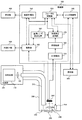
本発明の第1の実施形態に係る撮像装置を含む内視鏡システムについて、図1を用いて説明する。本実施形態に係る内視鏡システムは、光源部100と、撮像部200と、処理部300と、表示部400と、外部I/F部500と、操作部600を備えている。
2. First Embodiment An endoscope system including an imaging apparatus according to a first embodiment of the present invention will be described with reference to FIG. The endoscope system according to the present embodiment includes a
光源部100は、白色光を発生する白色光源110と白色光をライトガイドファイバ210に集光するための集光レンズ120を備えている。
The
撮像部200は、例えば体腔への挿入を可能にするため細長くかつ湾曲可能に形成されている。撮像部200には、光源部で集光された光を導くためのライトガイドファイバ210と、該ライトガイドファイバにより先端まで導かれてきた光を拡散させて観察対象に照射する照明レンズ220と、観察対象から戻る反射光を結像する対物レンズ230と、対物レンズ230に含まれ画角と合焦物体位置を同時に調整する可動レンズ240と、可動レンズ240を駆動するレンズ駆動部250と、対物レンズ230で結像された反射光を光電変換して画像を生成する撮像素子260を備えている。レンズ駆動部250は例えばボイスコイルモーター(以下、VCM)である。また、撮像素子260は例えばベイヤ配列の色フィルタを持つ撮像素子である。
The
図2に本実施形態における対物レンズ230の一例を示す。この対物レンズは、可動レンズ240の位置をWIDE端からTELE端に移動させた場合に、画角が狭くなる(光学倍率が大きくなる)と共に合焦物体位置が小さくなるような設計がなされている。具体的には、例えば可動レンズ位置を調整することで、図3に示すような合焦物体位置および被写界深度範囲を実現している。
FIG. 2 shows an example of the
処理部300はAD変換部310と、前処理部320と、フォーカス制御部330と、レンズ制御部340と、画像処理部350と、制御部360と、倍率補正処理部370と、基準レンズ位置設定部380と、を備えている。
The
AD変換部310は、撮像素子260から順次出力されるアナログ信号をデジタル画像に変換して、前処理部320に順次出力する。前処理部320はAD変換部310から出力された画像に対して、ホワイトバランス、補間処理(デモザイキング処理)等の画像処理を施し、倍率補正処理部370に順次出力する。倍率補正処理部370はフォーカス制御部330に接続されており、フォーカス制御部から出力される情報に従って、前処理部320から出力された画像に対して倍率補正処理を行い、フォーカス制御部330と画像処理部350に画像を順次出力する。倍率補正処理部370の詳細については後述する。
The
フォーカス制御部330はレンズ制御部340と、制御部360と、操作部600と、倍率補正処理部370に接続されており、操作部600から出力されるAF開始/終了信号に従ってAF制御を行う。この時フォーカス制御部330は、可動レンズ240に要求されるレンズ位置(要求レンズ位置)をレンズ制御部340に出力する。またフォーカス制御部330は、倍率補正処理に必要な情報を倍率補正処理部370に出力する。さらにフォーカス制御部330は、制御部360から撮像素子260の制御信号(例えば画像の取得を終了するタイミング信号等)を取得する。フォーカス制御部330の詳細については後述する。
The
レンズ制御部340は、レンズ駆動部250と、フォーカス制御部330と、操作部600に接続されており、操作部600およびフォーカス制御部330から出力される要求レンズ位置に従って可動レンズを制御する。操作部600の詳細については後述する。
The
画像処理部350は制御部360に接続されており、倍率補正処理部370から出力された画像信号に対して色変換、階調変換、エッジ強調、ノイズリダクション等の画像処理を施し、表示部400に画像信号を順次出力する。表示部400は例えば液晶モニタであり、画像処理部350から出力される画像信号を表示する。
The
基準レンズ位置設定部380は、倍率補正処理の基準となる可動レンズ240の位置である基準レンズ位置を設定する。倍率補正処理部370での倍率補正処理は、可動レンズ240の実際の位置によらず、あたかも設定された基準レンズ位置に可動レンズ240があるかのような画像を生成する処理となる。基準レンズ位置設定部380の詳細については後述する。
The reference lens
制御部360は外部I/F部500やフォーカス制御部330、画像処理部350、基準レンズ位置設定部380、撮像素子260などと相互に接続されており、これらを制御する。外部I/F部500は、内視鏡装置に対するユーザーからの入力等を行うためのインターフェースであり、画像処理のパラメータを調整するための調整ボタンなどを含んで構成されている。
The
次に操作部600の詳細について説明する。図4に本実施形態における操作部600の一例を示す。本実施形態において、操作部600は例えば撮像部200と一体化して構成されており、ズームレバー610とAFボタン620を備えている。ズームレバー610は、例えば一定の範囲を連続的に動作させることが可能であり、ユーザーはズームレバー610を動かすことで、可動レンズ240の位置をWIDE端からTELE端まで連続的に調整することができる。具体的には、例えば操作部600は、ズームレバー610の位置情報を要求レンズ位置に変換してレンズ制御部340に出力する。また、操作部600は例えばAFボタン620が押されるたびに、フルタイムAFの開始/終了信号を交互にフォーカス制御部330に出力する。
Next, details of the
ここで操作部600は例えば前述のAFボタン620を省いた構成としてもよい。この場合、例えばユーザーがズームレバーをTELE端からさらにTELE側に動かすことで、操作部600がフルタイムAFの開始信号をフォーカス制御部330に出力してもよい。この場合、ユーザーがズームレバーをTELE端に戻すことで、フルタイムAFの終了信号をフォーカス制御部330に出力してもよい。このような構成にすることで、ユーザーはズームレバーの操作のみで可能レンズの位置制御とフルタイムAFの開始/終了制御を行うことが可能になり、ユーザーの操作が複雑になることを避けることができる。
Here, the
ここで、本実施形態において通常観察および拡大観察を行う場合のユーザーの操作について、図3および図5を用いて説明する。まず、ユーザーはズームレバー610をWIDE端に移動させ、病変部を発見するための通常観察を行う(図3のズームレンズ位置A)。この時、撮像部200では図5(A)に示すように、画角および被写界深度が広い画像を取得することができる。本実施形態において、この時の被写界深度範囲は図3に示すように約10〜50mmである。
Here, a user operation when performing normal observation and magnified observation in the present embodiment will be described with reference to FIGS. 3 and 5. First, the user moves the
次にユーザーは、発見した病変部に対して撮像部200を徐々に近づけながら、病変部を拡大していく。本実施形態では病変部までの距離が10mm以下になると、病変部が被写界深度から外れてボケはじめる。この時、ユーザーはズームレバー610をTELE側に移動させ、被写界深度範囲を撮像部に近づける(図3のズームレンズ位置B〜C)。これにより病変部が被写界深度内に入るため、ユーザーは病変部の観察を継続することができる。
Next, the user enlarges the lesioned part while gradually bringing the
本実施形態においては、ズームレンズ位置がCの場合でも被写界深度範囲は約4〜7mmであり、ある程度の被写界深度が維持されている。このため、ユーザーがズームレバー610や撮像部200の位置を操作することで、容易に病変部にピントを合わせることが可能である。
In this embodiment, even when the zoom lens position is C, the depth of field range is about 4 to 7 mm, and a certain depth of field is maintained. Therefore, the user can easily focus on the lesioned part by operating the positions of the
次にユーザーは、撮像部200をさらに病変部に近づけながら、ズームレバー610をさらにTELE側に移動させ、病変部をより拡大する。本実施形態においては、可動レンズ位置がDよりもTELE側にあると、図3に示すように被写界深度範囲は1mm前後かそれ以下となる。このような条件下では、図5(B)に示すようにユーザーは被写体となる消化管の壁面に対して撮像部200をほぼ正対させた状態で観察を行う場合が多い。これは被写界深度が狭い場合、被写体に対して撮像部200を正対させないと、画像中のピントが合う領域が狭くなるからである。
Next, the user further moves the
このような場合においては、ユーザーがズームレバー610や撮像部200の位置を操作することで被写体にピントを合わせることが難しくなる。このため、ユーザーはAFボタン620を押してフルタイムAFを開始する。もしくは、前述のようにズームレバー610をTELE端からさらにTELE側に動かしてフルタイムAFを開始してもよい。これにより、ユーザーが容易に被写体にピントを合わせることが可能になる。
In such a case, it is difficult for the user to focus on the subject by operating the position of the
次に、本実施形態におけるフォーカス制御部330の詳細について、図12に示すフローチャートおよび図13(A)、図13(B)を用いて説明する。以降は、倍率補正処理部370からフォーカス制御部330に順次出力される画像を現在画像と呼ぶ。
Next, details of the
フォーカス制御部330は、制御部360からAF開始信号が出力された場合、現在画像の取得が終了したタイミングでカウンタwobCntを0、フルタイムAFの開始フラグstartFlagを1とする(S101)。さらにフォーカス制御部330は、レンズ制御部340から現在の可動レンズ240の位置lensPosNowを取得する。次にフォーカス制御部330は、画像の取得終了まで待機した後(S102)、wobCntが0(S103でYes)かつstartFlagが1(S104でYes)であるため、startFlagを0とし、wobCntを1とする(S105)。以後、startFlagは0のままである。またフォーカス制御部330は、要求レンズ位置lensPosReqを以下の式(1)で算出する。ここでwobLvlは、図13(A)に示すように可動レンズ240のウォブリング幅である。さらにフォーカス制御部330は、lensPosNowをウォブリングの中心位置を表すlensPosCentに代入する。
lensPosReq = lensPosNow + wobLvl ・・・・・(1)
When the AF start signal is output from the
lensPosReq = lensPosNow + wobLvl (1)
その後フォーカス制御部330はレンズ制御部340にlensPosReqを出力する(S106)。さらにフォーカス制御部330は、倍率補正処理部370にlensPosReqとlensPosCentを出力し、S102に戻る。
Thereafter, the
次にフォーカス制御部330は、wobCntが1である(S103でNo且つS107でYes)ため現在画像の取得が終了したタイミングで、現在画像のコントラスト値contrastValNowを取得し、これをcontrastValOldとして保存する(S108)。ここでは例えば現在画像に任意のAF領域を設定し、AF領域に含まれるすべての画素のG信号に対してHPF(high-pass filter)処理を行い、その出力値の総和をcontrastValNowとすればよい。なお、ここでの現在画像は図13(A)に示すように可動レンズ位置が増加する方向にウォブリングされた画像である。さらにフォーカス制御部330はwobCntを2とした後、lensPosReq を以下の式(2)で算出する(S109)。なお、ここでフォーカス制御部330は、lensPosCentの値は変更しない。
lensPosReq = lensPosNow - 2 * wobLvl ・・・・・(2)
Next, since wobCnt is 1 (No in S103 and Yes in S107), the
lensPosReq = lensPosNow-2 * wobLvl (2)
その後フォーカス制御部330はレンズ制御部340にlensPosReqを出力する。さらにフォーカス制御部330は、倍率補正処理部370にlensPosReqとlensPosCentを出力する(S106)。
Thereafter, the
次にフォーカス制御部330は、wobCntが2である(S103でNo且つS107でNo)ため現在画像の取得が終了したタイミングで、contrastValNowを取得する(S110)。なお、ここでの現在画像は図13(A)に示すように可動レンズ位置が減少する方向にウォブリングされた画像である。さらにフォーカス制御部330はwobCntを0とした後、lensPosReqを以下の式(3)で算出する(S111)。なお、ここでフォーカス制御部330は、lensPosCentの値は変更しない。
lensPosReq = lensPosNow + wobLvl ・・・・・(3)
Next, since wobCnt is 2 (No in S103 and No in S107), the
lensPosReq = lensPosNow + wobLvl (3)
その後フォーカス制御部330はレンズ制御部340にlensPosReqを出力する。さらにフォーカス制御部330は、倍率補正処理部370にlensPosReqとlensPosCentを出力する(S106)。これにより、可動レンズ位置はウォブリングの中心位置に戻ることになる。
Thereafter, the
次にフォーカス制御部330は、wobCntが0(S103でYes)かつstartFlagが0(S104でNo)であるため現在画像の取得が終了したタイミングで、上記で取得したcontrastValNowとcontrastValOldを比較する(S112)。contrastValOldがcontrastValNowよりも大きい場合(S112でYes)は、可動レンズ位置が増加する方向に合焦レンズ位置があると考えられるため、フォーカス制御部330はwobCntを1とした後、lensPosReqとlensPosCentを以下の式(4)、(5)で算出する(S113)。これにより図13(A)に示すようにウォブリングの中心位置が、可動レンズ位置が増加する方向に移動することになる。
lensPosReq = lensPosNow + wobLvl + shiftLvl ・・・・・(4)
lensPosCent = lensPosNow + shiftLvl ・・・・・(5)
Next, since wobCnt is 0 (Yes in S103) and startFlag is 0 (No in S104), the
lensPosReq = lensPosNow + wobLvl + shiftLvl (4)
lensPosCent = lensPosNow + shiftLvl (5)
その後フォーカス制御部330はレンズ制御部340にlensPosReqを出力する。さらにフォーカス制御部330は、倍率補正処理部370にlensPosReqとlensPosCentを出力する(S106)。
Thereafter, the
またcontrastValRefがcontrastValNowよりも小さい場合(S112でNo)は、可動レンズ位置が減少する方向に合焦レンズ位置があると考えられるため、フォーカス制御部330はwobCntを1とした後、lensPosReqとlensPosCentを以下の式(6)、(7)で算出する(S114)。これによりウォブリングの中心位置が、可動レンズ位置が減少する方向に移動することになる。
lensPosReq = lensPosNow + wobLvl - shiftLvl ・・・・・(6)
lensPosCent = lensPosNow - shiftLvl ・・・・・(7)
If contrastValRef is smaller than contrastValNow (No in S112), it is considered that the in-focus lens position is in the direction in which the movable lens position decreases. Therefore, after setting wobCnt to 1, focus
lensPosReq = lensPosNow + wobLvl-shiftLvl (6)
lensPosCent = lensPosNow-shiftLvl (7)
その後フォーカス制御部330はレンズ制御部340にlensPosReqを出力する。さらにフォーカス制御部330は、倍率補正処理部370にlensPosReqとlensPosCentを出力する(S106)。
Thereafter, the
以後も同様の動作を継続して行うことで、フォーカス制御部330は可動レンズ位置を徐々に合焦レンズ位置に近づけることで、最終的には合焦レンズ位置に到達し、被写体にピントを合わせることができる。また、被写体距離の変動などにより被写体がボケた場合も、上記の動作を継続して行うことで再度被写体にピントを合わせることが可能であるため、フルタイムAFが実現できることになる。
Thereafter, the same operation is continuously performed, so that the
次に、倍率補正処理部370における倍率補正処理の考え方について説明する。図8(A)は物体位置(被写体距離)を任意の固定値として、本実施形態における可動レンズ240をTELE端からWIDE端まで移動させた時の、物体高(物体面上での光軸からの距離)と像高(像面上での光軸からの距離)の関係を示した模式図である。最大像高は撮像素子の寸法で決まる固定値であり、可動レンズ240がTELE端からWIDE端に移動するに従って最大像高に対応する物体高が大きくなっている(画角が広くなっている)ことが分かる。このような可動レンズ240を用いてウォブリングを行う場合、ウォブリング時の可動レンズ240の位置がウォブリングの中心位置を基準としてTELE側にあるのかWIDE側にあるのかによって、被写体の像面上の位置が変化する。例えば物体高xの位置にある被写体の像高は、図8(B)に示すように可動レンズ240がTELE側にある場合はx’_TELEとなり、WIDE側にある場合はx’_WIDEとなる。この結果、ウォブリング時に画像のちらつきが発生するため、これを防止するために倍率補正処理部370で倍率補正処理を行う必要がある。
Next, the concept of magnification correction processing in the magnification
さらに、本実施形態のようにフォーカス制御部330に入力される前の画像に対して倍率補正処理を行うことで、可動レンズ240がTELE側にある場合もWIDE側にある場合も、フォーカス制御部330で設定されるAF領域に対応する被写体の範囲を等しくすることができるため、フルタイムAFの精度を向上させることが可能になる。
Furthermore, by performing magnification correction processing on the image before being input to the
次に、基準レンズ位置設定部380における基準レンズ位置の設定処理について説明する。上述したように、本実施形態ではウォブリング動作の一周期の中で一定の基準を設定できればよいことを想定しており、且つ実際の画角と倍率補正処理後の画像の画角との乖離が大きくならないことが望ましい。以上を考慮すれば、処理対象としているウォブリング動作の周期での、TELE端とWIDE端の間のいずれかの位置を基準レンズ位置として設定すればよいことになる。例えば、ウォブリング動作の中心位置、TELE端、WIDE端のいずれかをレンズ基準位置とすると設定が容易である。
Next, reference lens position setting processing in the reference lens
ただし、ウォブリングを用いたフルタイムAFでは、画像のボケが大きい場合はウォブリング量を大きくしなければ、合焦レンズ位置の方向を判別できない。一方、画像のボケが小さい場合は、ウォブリング量が大きすぎるとボケの大きい画像と小さい画像が交互に表示されることになり不自然な画像となる。このため、フルタイムAF中にウォブリング量を変化させることも考えられる。このため、ウォブリングのTELE側もしくはWIDE側の可動レンズ位置を基準レンズ位置として倍率補正処理を行うと、ウォブリング量を変更した場合に倍率補正処理後の画像の画角が変化し、違和感のある画像となる。このため本実施形態では、ウォブリング時にTELE側、WIDE側で取得された画像に対して、ウォブリングの中心位置を基準レンズ位置として倍率補正処理を行うことが考えられる。なお、以下の説明では基準レンズ位置はウォブリング動作の中心位置(lensPosCent)であるものとするが、上述したように状況によってはこれに限定されるものではない。 However, in full-time AF using wobbling, if the image blur is large, the direction of the in-focus lens position cannot be determined unless the wobbling amount is increased. On the other hand, when the blur of the image is small, if the wobbling amount is too large, an image with a large blur and a small image are alternately displayed, resulting in an unnatural image. For this reason, it is conceivable to change the wobbling amount during full-time AF. For this reason, if the magnification correction process is performed with the movable lens position on the TELE side or WIDE side of wobbling as the reference lens position, the angle of view of the image after the magnification correction process changes when the wobbling amount is changed, and the image is uncomfortable. It becomes. For this reason, in the present embodiment, it is conceivable to perform magnification correction processing with respect to an image acquired on the TELE side and WIDE side during wobbling, using the center position of wobbling as a reference lens position. In the following description, the reference lens position is assumed to be the center position (lensPosCent) of the wobbling operation. However, as described above, the reference lens position is not limited to this.
基準レンズ位置が設定されたものとして、倍率補正処理の説明に戻る。可動レンズ240の位置がウォブリングの中心にある場合、被写体の像面上の位置は、図8(B)に示すようにx’_CENTである。このため、TELE側で取得された画像に対しては、x’_TELEに位置している被写体がx’_CENTに移動するように倍率補正処理を行う。具体的には補正係数Kを以下の式(8)で算出し、画像全体にK倍の倍率補正処理を行う。
K = x’_CENT / x’_TELE ・・・・・(8)
Returning to the description of the magnification correction process, assuming that the reference lens position is set. When the position of the
K = x'_CENT / x'_TELE (8)
また、WIDE側で取得された画像に対しても同様に、補正係数Kを以下の式(9)で算出し、画像全体にK倍の倍率補正処理を行う。
K = x’_CENT / x’_WIDE ・・・・・(9)
Similarly, for the image acquired on the WIDE side, the correction coefficient K is calculated by the following equation (9), and a magnification correction process of K times is performed on the entire image.
K = x'_CENT / x'_WIDE (9)
光軸中心から最大像高までのすべての像高に対して、補正係数Kがほぼ一定の値となるように対物レンズが設計されていれば、このような処理により画像全体で高精度な倍率補正を実現することができる。また、像高に対する補正係数Kの変化量が大きい場合は、像高に応じてKの値を算出するようにしてもよい。倍率補正処理の詳細については後述する。 If the objective lens is designed so that the correction coefficient K is a substantially constant value for all image heights from the center of the optical axis to the maximum image height, this process ensures high-precision magnification throughout the image. Correction can be realized. If the change amount of the correction coefficient K with respect to the image height is large, the value K may be calculated according to the image height. Details of the magnification correction processing will be described later.
なおフルタイムAFを行っている場合、前述したようにウォブリングの中心位置は、合焦レンズ位置に近づくように変化する。このため倍率補正処理部370は、ウォブリングの中心位置がどこであっても高精度な倍率補正を実現できる必要がある。
When full-time AF is performed, the wobbling center position changes so as to approach the in-focus lens position as described above. Therefore, the magnification
本実施形態における倍率補正処理部370の詳細について、図6を用いて説明する。倍率補正処理部370は、補正処理部371と、補正係数算出部372と、メモリ373を備えている。補正係数算出部372は、フォーカス制御部330から出力されるlensPosReqと、基準レンズ位置設定部380から出力される基準レンズ位置(ここではlensPosCent)、およびメモリ373に保存されている補正係数算出用のデータから補正係数Kを算出し、補正処理部371に出力する。補正処理部371は、補正係数算出部372から出力されるKを用いて、前処理部320から出力される画像に対して補正処理を行い、補正処理後の画像をフォーカス制御部330および画像処理部350に出力する。
Details of the magnification
ここで、補正係数算出部372における補正係数Kの算出手法について説明する。図15はメモリ373に保存されている補正係数算出用データの一例である。ここではTELE端からWIDE端における複数の可動レンズ位置A〜Fと、それぞれのレンズ位置における被写体の像高x’_A〜x’_Fが保存されている。ここで像高x’_A〜x’_Fは、例えば図8(A)に示したような可動レンズ240の各レンズ位置に対する物体高と像高の関係を対物レンズの設計データから算出し、任意の物体高xを用いて決定すればよい。
Here, a method of calculating the correction coefficient K in the correction
本実施形態では、前述したようにフルタイムAFを行っている場合、フォーカス制御部330からlensPosReqが順次出力されるとともに、基準レンズ位置設定部380からlensPosCentが順次出力されている。補正係数算出部372はまず可動レンズ240がlensPosReqに位置する場合の像高x’_REQを算出する。ここでは例えば、まずレンズ位置A〜Fのうち、lensPosReqを間に挟む2点の可動レンズ位置を検出し(ここでは可動レンズ位置EとFの間にlensPosReqがあるとする)、この2点のレンズ位置とそれに対応する像高(ここではx’_Eとx’_F)から図9に示すような線形補間を用いてx’_REQを算出すればよい。次に補正係数算出部372は、可動レンズ240がlensPosCentに位置する場合の像高x’_CENTを、x’_REQと同様の手法で算出する。その後、補正係数算出部372は以下の式(10)でKを算出し、補正処理部371に順次出力する。
K = x’_CENT / x’_REQ ・・・・・(10)
In the present embodiment, as described above, when full-time AF is performed, lensPosReq is sequentially output from the
K = x'_CENT / x'_REQ (10)
次に、補正処理部371における補正処理の詳細について説明する。補正処理部371はまず補正処理後の画像における、画素値を算出したい注目画素の座標(outX,outY)を取得する。ここで(outX,outY)は図10(A)に示すように、左上画素を基準とした座標である。次に補正処理部371は図10(B)に示すように、注目画素の座標(outX,outY)を、以下の式(11)、(12)を用いて画像中心(光軸に対応する画像上の点)を基準とした座標(shiftX,shiftY)に変換する。ここで(centX,centY)は、画像中心の座標である。
shiftX = outX - centX ・・・・・(11)
shiftY = outY - centY ・・・・・(12)
Next, details of the correction processing in the
shiftX = outX-centX (11)
shiftY = outY-centY (12)
次に補正処理部371は、以下の式(13)、(14)を用いて(shiftX,shiftY)に対応する補正処理前の画像の座標(inShiftX,inShiftY)を算出する。(inShiftX,inShiftY)は、画像中心を基準とした座標であり、図10(C)はKが1より大きい時の(shiftX,shiftY)と(inShiftX,inShiftY)の関係を示している。
inShiftX = shiftX / K ・・・・・(13)
inShiftY = shiftY / K ・・・・・(14)
Next, the
inShiftX = shiftX / K (13)
inShiftY = shiftY / K (14)
次に補正処理部371は、算出した座標(inShiftX,inShiftY)を、以下の式(15)、(16)を用いて、画像の左上画素を基準とした座標(inX,inY)に変換する。この座標(inX,inY)が、補正処理後の注目画素の座標(outX, outY)に対応する変倍処理前の画像の座標である。
inX = inShiftX + centX ・・・・・(15)
inY = inShiftY + centY ・・・・・(16)
Next, the
inX = inShiftX + centX (15)
inY = inShiftY + centY (16)
このため、Kが1より大きい場合は、図10(C)に示すように(inX,inY)は(outX,outY)と比較して画像中心に近づく方向に移動することになる。またKが1より小さい場合は、(inX,inY)は(outX,outY)と比較して画像中心から遠ざかる方向に移動することになる。 For this reason, when K is larger than 1, (inX, inY) moves in a direction closer to the image center as compared with (outX, outY) as shown in FIG. When K is smaller than 1, (inX, inY) moves in a direction away from the image center as compared with (outX, outY).
次に補正処理部371は、算出した補正処理前の画像の座標(inX,inY)から、補正処理後の注目画素(outX,outY)の画素値I(outX,outY)を算出する。ここでは例えばバイリニア法など補間処理を用いて注目画素の画素値を算出すればよい。具体的には図11に示すように、補正処理前の画像において、(inX,inY)の周辺に位置する4画素の画素値p00,p01,p10,p11を用いて以下の式(17)でI(outX,outY)を算出すればよい。また、その他の既存の補間処理を用いても、I(outX,outY)を算出することが可能であることは言うまでもない。
I(outX, outY) = ( floor(inX) + 1 - inX ) * ( floor(inY) + 1 - inY ) * p00
+ ( floor(inX) + 1 - inX ) * ( inY - floor(inY) ) * p10
+ ( inX - floor(inX) ) * ( floor(inY) + 1 - inY ) * p01
+ ( inX - floor(inX) ) * ( inY - floor(inY) ) * p11 ・・・・・(17)
Next, the
I (outX, outY) = (floor (inX) + 1-inX) * (floor (inY) + 1-inY) * p00
+ (floor (inX) + 1-inX) * (inY-floor (inY)) * p10
+ (inX-floor (inX)) * (floor (inY) + 1-inY) * p01
+ (inX-floor (inX)) * (inY-floor (inY)) * p11 (17)
また、Kが1よりも小さい場合は前述のように、(inX,inY)は(outX,outY)と比較して画像中心から遠ざかる方向に移動する。このため、(outX,outY)が画像の周辺付近に位置する場合は、(inX,inY)が画像の外側に位置することになり、補正処理後の画素値I(outX,outY)が算出できなくなる場合がある。このような場合は、図10(D)に示すように画像として使用される有効領域の外側にあらかじめ余裕領域を準備しておき、余裕領域の画素値を使用してI(outX,outY)を算出するようにすればよい。 When K is smaller than 1, (inX, inY) moves in a direction away from the image center as compared with (outX, outY) as described above. For this reason, when (outX, outY) is located near the periphery of the image, (inX, inY) is located outside the image, and the pixel value I (outX, outY) after correction processing can be calculated. It may disappear. In such a case, as shown in FIG. 10D, a margin area is prepared in advance outside the effective area used as an image, and I (outX, outY) is calculated using the pixel value of the margin area. What is necessary is just to calculate.
補正処理部371は、前処理部320から順次出力される画像に対して、RGBすべてのチャンネルでこのような倍率補正処理を行い、フォーカス制御部330および画像処理部350に順次出力する。この結果、ウォブリング時にTELE側、WIDE側で取得された画像が、図13(B)に示すように見かけ上はウォブリングの中心位置で取得された画像のように補正されるため、表示部400ではウォブリング時のちらつきが無く、違和感のない画像を表示することが可能になる。
The
なお、前述したようにユーザーがフルタイムAFを行うのは、一般的にTELE端付近が多いと考えられるため、ここでは例えばレンズ位置D〜Fとそれに対応する像高x’_D〜x’_Fのみをメモリ373に保存しておき、フォーカス制御部330はこの範囲のみで可動レンズ240を制御してフルタイムAFを行うようにしてもよい。
As described above, it is considered that the user performs full-time AF generally in the vicinity of the TELE end. Therefore, here, for example, the lens positions D to F and the corresponding image heights x′_D to x′_F are used. May be stored in the
また、他の変形例として、撮像装置はAF処理後の合焦レンズ位置を用いて被写体までの距離を算出する距離計測部を備えてもよい。フォーカスレンズ位置に対応する合焦物体位置は光学的な特性から一意に決定されるものであるため、フォーカスレンズ位置が所与の位置であることが決定されれば、その際の合焦物体位置を求めることができる。ここでAF処理が正常に終了した後のフォーカスレンズ位置とは、撮像対象としている被写体に合焦していることが期待される合焦レンズ位置であることから、その際の被写体は合焦物体位置に相当する位置にあると推定できる。このため距離計測部は例えば、合焦レンズ位置と合焦物体位置の関係を表すテーブルデータをメモリに保存しておき、AF処理後の合焦レンズ位置からこのテーブルデータを用いて合焦物体位置を算出し、これを被写体までの距離とすればよい。 As another modification, the imaging apparatus may include a distance measurement unit that calculates the distance to the subject using the focus lens position after the AF process. Since the focus object position corresponding to the focus lens position is uniquely determined from optical characteristics, if the focus lens position is determined to be a given position, the focus object position at that time is determined. Can be requested. Here, the focus lens position after the AF processing is normally completed is a focus lens position where it is expected to be focused on the subject to be imaged, and the subject at that time is the focused object. It can be estimated that the position is equivalent to the position. For this reason, the distance measurement unit stores, for example, table data representing the relationship between the focus lens position and the focus object position in the memory, and uses the table data from the focus lens position after the AF process to perform the focus object position. May be calculated and used as the distance to the subject.
つまり、本実施形態の手法はAFを適切に行うものであるが、AFの結果(特にフォーカスレンズ位置)を用いて被写体までの距離を表す距離情報を算出することが可能である。取得した距離情報をどのような処理に利用するかは任意であるが、例えば距離情報から被写体の構造等を推定し、特定の凹凸構造に対して視認性を高めるための強調処理を行うことや、距離情報が所定の閾値以下であれば被写体である生体に接触する可能性があるとしてアラートを行うこと等が考えられる。 That is, the method of the present embodiment appropriately performs AF, but it is possible to calculate distance information representing the distance to the subject using the AF result (particularly the focus lens position). It is arbitrary what kind of processing the acquired distance information is used for, for example, the structure of the subject is estimated from the distance information, and emphasis processing is performed to improve the visibility for a specific uneven structure, If the distance information is equal to or less than a predetermined threshold value, it may be possible to perform an alert, etc., because there is a possibility of contact with a living body as a subject.
以上の本実施形態では、撮像装置は図16や図1に示したように、画角の変更に伴い合焦物体位置が変更される可動レンズ240を含む対物レンズ230と、対物レンズ230で結像された被写体像を光電変換して画像を取得する撮像素子260と、可動レンズ240の位置を制御することによりフルタイムAF(AutoFocus)を行うフォーカス制御部330と、フルタイムAFにおける可動レンズの基準位置である基準レンズ位置を設定する基準レンズ位置設定部380と、基準レンズ位置と可動レンズの位置に基づいて、画像に対して倍率補正処理を行う倍率補正処理部370を含む。そして、基準レンズ位置設定部380は、フルタイムAFでのウォブリング動作による可動レンズの移動範囲に基づいて、基準レンズ位置を設定し、倍率補正処理部370は、設定された基準レンズ位置に対する、ウォブリング動作時の可動レンズの位置の変動による、画像の画角の変動を低減する処理を、倍率補正処理として行う。
In the above-described embodiment, as shown in FIG. 16 and FIG. 1, the imaging apparatus is connected with the
ここで、フルタイムAFとは、図12のフローチャートや、図13(A)、図13(B)を用いて説明したように、ウォブリング動作により可動レンズ240を移動させ、各可動レンズ位置で取得された画像から求めたコントラスト値を比較することで、可動レンズ240の位置を合焦レンズ位置(合焦状態にある場合のレンズの位置)に近づける制御である。
Here, full-time AF is acquired at each movable lens position by moving the
これにより、設定した基準レンズ位置を基準とした場合の可動レンズ240の位置変動を補償する倍率補正処理が行われるため、図13(A)のA1,A2に示したようなウォブリング動作が行われる場合であっても、画像上では当該ウォブリング動作に伴う可動レンズ240の移動が少ない(理想的にはキャンセルされた)ように見せることが可能になる。よって、倍率補正処理後の画像を用いてAF評価値(コントラスト値等)の算出を行うことで、AF評価値を安定的に算出できるため、AF制御を精度よく行うことが可能になる。また、高頻度での画角の変動を抑止できるため、ユーザーに対して見やすい画像を提示することができる。これは病変部の観察等が想定される内視鏡分野においては非常に有用である。
As a result, magnification correction processing is performed to compensate for positional fluctuations of the
また、基準レンズ位置設定部380は、可動レンズ240のウォブリング動作の中心位置(lensPosCent)、又はウォブリング動作での望遠側端点を表す最遠点(lensPosCent+wobLvl)、又はウォブリング動作での広角側端点を表す最近点(lensPosCent-wobLvl)に基づいて、基準レンズ位置を設定してもよい。
In addition, the reference lens
これにより、ウォブリング動作の一周期内において、一定の基準レンズ位置を容易に設定することが可能になる。中心位置やウォブリング幅はフォーカス制御部330で設定されるもので取得が容易であるため、中心位置、最遠点、最近点ともに複雑な処理を行うことなく取得可能である。
This makes it possible to easily set a fixed reference lens position within one cycle of the wobbling operation. Since the center position and the wobbling width are set by the
また、基準レンズ位置設定部380は、可動レンズ240のウォブリング動作の中心位置を、基準レンズ位置として設定してもよい。
Further, the reference lens
これにより、上述したように中心位置(lensPosCent)を基準レンズ位置とできるため、容易に基準レンズ位置を設定可能である。また、最遠点及び最近点は、ウォブリング幅(wobLvl)が異なればその位置が異なるものになるところ、上述したように所与のウォブリング周期と、他のウォブリング周期とでウォブリング幅を変化させるケーズは十分に考えられるが、その場合問題が生ずる可能性がある。極端な例を図17に示す。第1のウォブリング周期B7では、B1,B2に示す大きなウォブリング幅でウォブリング動作を行い、結果としてB5に示したシフトレベルで、可動レンズ240の位置が増大する方向にシフトしたとする。そして、第2のウォブリング周期B8では、シフト後の中心位置を用いて、B3,B4に示す小さなウォブリング幅でウォブリング動作を行った。この場合、最遠点を基準レンズ位置とすると、第1のウォブリング周期B7でも第2のウォブリング周期B8でも、レンズ基準位置はB6で示した位置となる。しかし、B5に示したように、フルタイムAFの制御としては可動レンズ240の位置は増大する方向へのシフトを示しているのに、その結果が画像上全く反映されないという事態になり、ユーザーに対して違和感を与えてしまう。その点、中心位置をレンズ基準位置とすれば、B7ではレンズ基準位置はB9となり、B8ではレンズ基準位置はB10となるため、B5のシフト分が基準レンズ位置(及び倍率補正処理後の画像の画角)に反映可能という利点がある。
Thereby, since the center position (lensPosCent) can be set as the reference lens position as described above, the reference lens position can be easily set. Also, the farthest point and the nearest point have different positions if the wobbling width (wobLvl) is different. As described above, the wobbling width is changed between a given wobbling period and other wobbling periods. Is well thought out, but it can cause problems. An extreme example is shown in FIG. In the first wobbling cycle B7, it is assumed that a wobbling operation is performed with a large wobbling width indicated by B1 and B2, and as a result, the position of the
また、フォーカス制御部330は、第1のウォブリング周期において、第1の位置を中心に第1のウォブリング幅で可動レンズ240を動作させる第1のウォブリング動作を、ウォブリング動作として行って第1のAF処理を行い、第1のウォブリング周期の次の第2のウォブリング周期において、第1のAF処理の結果に基づいて設定された第2の位置を中心に第2のウォブリング幅で可動レンズ240を動作させる第2のウォブリング動作を、ウォブリング動作として行って第2のAF処理を行ってもよい。その場合、基準レンズ位置設定部380は、第1のウォブリング周期では、第1のウォブリング動作による可動レンズ240の移動範囲に基づいて、第1の基準レンズ位置を基準レンズ位置として設定し、第2のウォブリング周期では、第2のウォブリング動作による可動レンズ240の移動範囲に基づいて、第2の基準レンズ位置を基準レンズ位置として設定する。
Further, the
これにより、ウォブリング周期毎に、対象とする周期での可動レンズ240の位置に応じて基準レンズ位置を設定することが可能になる。ウォブリング周期毎に基準レンズ位置が設定されるため、図13(A)のA1〜A4に示したような細かな可動レンズ240の移動による画角への影響を抑止しつつ、A5に示したシフト(つまりはフルタイムAFによる大局的な可動レンズ240の制御)を適切に画像に反映させることが可能になる。よって、ユーザーに対して見やすい画像を提供するとともに、上述したような撮像素子の性能を十分発揮できないという問題が生じる可能性も抑止することができる。
Accordingly, it is possible to set the reference lens position according to the position of the
また、倍率補正処理部370は、倍率補正処理の出力として、撮像素子260で取得される画像に比べて画素数の少ない出力画像を出力してもよい。
The magnification
さらに、撮像素子260で取得される画像のうち、中央領域を有効領域とし、画像のうち有効領域でない周縁領域を余裕領域とした場合に、倍率補正処理部370は、倍率補正処理として拡大処理が行われる場合には、有効領域に基づいて出力画像を生成し、倍率補正処理として縮小処理が行われる場合には、有効領域と余裕領域とに基づいて出力画像を生成してもよい。
Furthermore, when the center area is an effective area among the images acquired by the
これにより、図10(D)に示したように、倍率補正処理として縮小処理が行われる場合にも、出力画像の各画素に対して適切に情報を割り当てることが可能になる。縮小処理では図10(D)に示したように所与の画素の出力値は、当該画素よりも周縁部側の画素値を用いて決定することになるため、場合によっては(inX,inY)に当たる周縁画素が存在せず、出力画像の周縁部の情報が取得できないおそれもある。その点、あらかじめ撮像された画像の周縁部を余裕領域として設定しておけば、縮小処理時にも当該余裕領域の画素を用いることで、出力画像の情報欠落を抑止することができる。なお、倍率補正処理の係数(上記K)はウォブリング幅でその上限下限が決定されるものであり、ウォブリング幅は一般的に極端に大きな値をとることはない。つまり、十分な余裕領域を設けたとしても、有効領域の撮像画像全体に占める割合を大きくすることができるため、撮像素子の性能(撮像素子自体の画素数)に対して倍率補正処理後の画像の画素数が極端に下がるおそれは小さい。 As a result, as shown in FIG. 10D, even when the reduction process is performed as the magnification correction process, it is possible to appropriately assign information to each pixel of the output image. In the reduction process, as shown in FIG. 10D, the output value of a given pixel is determined using the pixel value on the peripheral side of the pixel, and in some cases (inX, inY) There is no peripheral pixel corresponding to the above, and there is a possibility that information on the peripheral part of the output image cannot be acquired. In this regard, if the peripheral portion of the image captured in advance is set as a margin area, information loss in the output image can be suppressed by using the pixels in the margin area even during the reduction process. Note that the upper limit and the lower limit of the magnification correction processing coefficient (K) is determined by the wobbling width, and the wobbling width generally does not take an extremely large value. In other words, even if a sufficient margin area is provided, since the ratio of the effective area to the entire captured image can be increased, the image after magnification correction processing is performed on the performance of the imaging element (the number of pixels of the imaging element itself). There is little possibility that the number of pixels will be extremely reduced.
また、倍率補正処理部370は、倍率補正処理後の画像をフォーカス制御部330に出力し、フォーカス制御部330は、倍率補正処理部370から出力された倍率補正処理後の画像に基づいて、フルタイムAFを行ってもよい。
Further, the magnification
これにより、倍率補正処理後の画像を用いてフルタイムAF(狭義にはそのうちのコントラスト値の算出)を行うことができるため、精度よくAF制御を行うことが可能になる。これは上述したように、倍率補正処理は画角の変動を低減する処理であるため、その結果を用いることで、比較すべき画像間でのコントラスト値の算出基準の変動(例えば同等のエッジが一方では高周波側に、他方では低周波側へシフトする等の変動や、コントラスト値の算出対象であるAF領域に含まれる被写体範囲の変動)を抑止し、コントラスト値の比較処理を正確に行うことができるためである。 As a result, full-time AF (calculation of the contrast value in a narrow sense) can be performed using the image after the magnification correction processing, so that AF control can be performed with high accuracy. As described above, since the magnification correction process is a process for reducing the variation in the angle of view, by using the result, the variation in the calculation reference of the contrast value between the images to be compared (for example, an equivalent edge is detected). The contrast value is accurately compared by suppressing fluctuations such as shifting to the high frequency side on the one hand, and shifting to the low frequency side on the other hand, and fluctuations in the subject range included in the AF area for which the contrast value is calculated. It is because it can do.
また、可動レンズ240の可動範囲のうち、最も望遠側の可動レンズ240の位置を望遠端とし、最も広角側の可動レンズ240の位置を広角端とした場合に、フォーカス制御部330は、広角端と望遠端の間で任意に設定された所定の位置と、望遠端との間に可動レンズ240が位置する場合に、フルタイムAFを実行してもよい。
Further, when the position of the
これにより、所与の位置に対して望遠側に可動レンズ240がある場合に、フルタイムAFを行うことが可能になる。上述したように、AFは手動でのピント合わせが困難であるケースで特に有効であり、手動ピント合わせが困難な状況としては被写界深度範囲の狭い拡大観察時が考えられる。すなわち、可動レンズ240が望遠側にある場合にフルタイムAFを動作させることで、効率的なフォーカス制御を行うことができる。
This makes it possible to perform full-time AF when the
また、撮像装置は、可動レンズ240の位置をユーザーが調整するためのズームレバー(例えば図4に示したズームレバー610)を有する操作部600を含み、フォーカス制御部330は、ユーザーによるズームレバーを操作により、フルタイムAFの開始及び終了の少なくとも一方を決定してもよい。
The imaging apparatus also includes an
これにより、ユーザーの明示的な操作に基づいてフルタイムAFの開始、終了を決定することが可能になる。AFが効果的な状況で自動的にAFを動作させることが有用な状況も十分考えられるが、ユーザーが認識していないうちに勝手にAFが始まることが、かえって操作を妨げてしまう状況もあり得る。よって、AFの開始、終了の決定をユーザー操作に基づいて決定するというインターフェースが有用となる場合も多い。 Thereby, it is possible to determine the start and end of full-time AF based on an explicit operation of the user. There are situations where it is useful to automatically operate AF in situations where AF is effective, but there are also situations where AF starts without permission before the user is actually hindering the operation. obtain. Therefore, an interface that determines whether to start and end AF based on a user operation is often useful.
また、可動レンズ240の可動範囲のうち、最も望遠側の可動レンズ240の位置を望遠端とし、最も広角側の可動レンズ240の位置を広角端とした場合に、フォーカス制御部330は、望遠端に対応する望遠端レバー位置にズームレバー610を移動する操作が行われ、且つ望遠端レバー位置からさらに望遠側にズームレバー610を移動する操作が行われた場合に、フルタイムAFの開始を決定してもよい。
Further, when the position of the
これにより、ズームレバー610を用いたAF開始操作を実現することが可能になる。上述したように、ユーザーがAF開始を意図していない状況でAFが開始されることが好ましくない場合がある。その場合、AFとは関係なく通常行われる操作がAF開始のトリガーとなることは避けるべきである。よって例えば、望遠端に対応するレバー位置までズームレバー610を動かした上で、さらに望遠側に操作するという、通常の操作では行われる可能性が低い操作を、AF開始のトリガーとするとよい。この場合、図4に示したAFボタン620を省略できるため、操作部600の構成を簡略化することが可能になる。
Thereby, it is possible to realize an AF start operation using the
なお、本実施形態の撮像装置等は、その処理の一部または大部分をプログラムにより実現してもよい。この場合には、CPU等のプロセッサがプログラムを実行することで、本実施形態の撮像装置等が実現される。具体的には、非一時的な情報記憶媒体に記憶されたプログラムが読み出され、読み出されたプログラムをCPU等のプロセッサが実行する。ここで、情報記憶媒体(コンピュータにより読み取り可能な媒体)は、プログラムやデータなどを格納するものであり、その機能は、光ディスク(DVD、CD等)、HDD(ハードディスクドライブ)、或いはメモリ(カード型メモリ、ROM等)などにより実現できる。そして、CPU等のプロセッサは、情報記憶媒体に格納されるプログラム(データ)に基づいて本実施形態の種々の処理を行う。即ち、情報記憶媒体には、本実施形態の各部としてコンピュータ(操作部、処理部、記憶部、出力部を備える装置)を機能させるためのプログラム(各部の処理をコンピュータに実行させるためのプログラム)が記憶される。 Note that the imaging apparatus or the like of the present embodiment may realize part or most of the processing by a program. In this case, the imaging device and the like of this embodiment are realized by a processor such as a CPU executing a program. Specifically, a program stored in a non-temporary information storage medium is read, and a processor such as a CPU executes the read program. Here, the information storage medium (computer-readable medium) stores programs, data, and the like, and functions as an optical disk (DVD, CD, etc.), HDD (hard disk drive), or memory (card type). It can be realized by memory, ROM, etc. A processor such as a CPU performs various processes of the present embodiment based on a program (data) stored in the information storage medium. That is, in the information storage medium, a program for causing a computer (an apparatus including an operation unit, a processing unit, a storage unit, and an output unit) to function as each unit of the present embodiment (a program for causing the computer to execute processing of each unit) Is memorized.
また、以上の本実施形態は、画角の変更に伴い合焦物体位置が変更される可動レンズ240を含む対物レンズ230で結像された被写体像を光電変換した画像を取得する処理を行い、フルタイムAF(AutoFocus)における可動レンズ240の基準位置である基準レンズ位置を、フルタイムAFでのウォブリング動作による可動レンズ240の移動範囲に基づいて設定する処理を行い、基準レンズ位置と可動レンズ240の位置に基づいて、基準レンズ位置に対する、ウォブリング動作時の可動レンズ240の位置の変動による、画像の画角の変動を低減する倍率補正処理を、画像に対して行う撮像装置の制御方法(撮像装置の作動方法)に適用することができる。
Further, the present embodiment described above performs a process of obtaining an image obtained by photoelectrically converting a subject image formed by the
3.第2の実施形態
次に、第2の実施形態に係る撮像装置を含む内視鏡システムについて説明する。本実施形態の内視鏡システムは、基準レンズ位置設定部380以外は第1の実施形態と同様である。
3. Second Embodiment Next, an endoscope system including an imaging apparatus according to a second embodiment will be described. The endoscope system of the present embodiment is the same as that of the first embodiment except for the reference lens
本実施形態における基準レンズ位置設定部380(及び倍率補正処理部370)の詳細について、図7を用いて説明する。基準レンズ位置設定部380は、基準レンズ位置算出部384と、第2メモリ385を備えている。本実施形態では、フォーカス制御部330から順次出力されるlensPosCentはまず第2メモリ385に保存される。第2メモリ385には現在のlensPosCentの値と、そこから過去N個分のlensPosCentの値が保存されるようになっている。基準レンズ位置算出部384は、第2メモリ385に保存された複数のlensPosCentから、倍率補正処理の目標となる基準レンズ位置lensPosTargetを算出し、補正係数算出部372に順次出力する。具体的には、基準レンズ位置算出部384は第2メモリ385に保存されているすべてのlensPosCentの平均値をlensPosTargetとして算出する。
Details of the reference lens position setting unit 380 (and the magnification correction processing unit 370) in the present embodiment will be described with reference to FIG. The reference lens
補正係数算出部372は、フォーカス制御部330から順次出力されるlensPosReqと、基準レンズ位置算出部384から順次出力されるlensPosTargetを用いて補正係数Kを算出し、補正処理部371に出力する。ここでは例えば補正係数算出部372は、第1の実施形態におけるlensPosCentの代わりにlensPosTargetを使用し、第1の実施形態と同様の手法でKを算出すればよい。その後、補正処理部371は第1の実施形態と同様の手法で倍率変動補正を行う。
The correction
第1の実施形態で説明したように、フルタイムAF中にウォブリングの中心位置は、合焦レンズ位置に近づくようにWIDE側かTELE側かに常に変化する。このため図14に示すようにウォブリングの中心位置は、合焦後も合焦レンズ位置を挟んでWIDE側とTELE側とを往復しながら移動することになる。この往復の振幅が大きい場合は、ウォブリングの中心位置を目標として精度良く倍率変動補正を行った場合も、ウォブリング中心位置の往復に伴って倍率変動補正後の画像の画角が経時的に変化し違和感のある画像となる。このため本実施形態のように、lensPosCentと比較して変化が小さいlensPosTargetを倍率変動補正の目標とすることで、合焦後も画角の変化が少ない自然な画像を実現することができる。 As described in the first embodiment, during full-time AF, the wobbling center position always changes from the WIDE side to the TELE side so as to approach the focusing lens position. For this reason, as shown in FIG. 14, the wobbling center position moves while reciprocating between the WIDE side and the TELE side across the focusing lens position even after focusing. When the amplitude of this round trip is large, even when the magnification fluctuation correction is performed accurately with the wobbling center position as the target, the angle of view of the image after the magnification fluctuation correction changes with time as the wobbling center position is reciprocated. The image becomes uncomfortable. For this reason, as in this embodiment, by setting lensPosTarget, which has a smaller change than lensPosCent, as a target for correcting the magnification fluctuation, a natural image with little change in the angle of view can be realized even after focusing.
以上の本実施形態では、撮像装置の基準レンズ位置設定部380は、可動レンズ240のウォブリング動作の中心位置を時間的に平均することで求められる位置を、基準レンズ位置として設定する。
In the present embodiment described above, the reference lens
これにより、図14に示したように、ウォブリング動作の中心位置が合焦レンズ位置に近い状況となった場合にも、適切なレンズ基準位置を設定することが可能になる。フルタイムAFでは意図的にAF動作を終了させない限り、ウォブリング周期の終了後にはシフトレベルだけ中心位置が移動してしまうことが一般的である。そのため、中心位置が合焦レンズ位置に近い場合には、当該合焦レンズ位置の周辺で中心位置が振動するケースが生じうる。そのような振動する中心位置をレンズ基準位置とすると、倍率補正処理で取得される画像の画角もレンズ基準位置に応じて振動するため見づらいものとなる。その点、上述の振動周期に比べて長い周期での中心位置の平均をとれば、当該平均値は合焦レンズ位置に近い値となることが期待されるため、倍率補正処理後の画像の画角変動を低減することが可能である。 As a result, as shown in FIG. 14, even when the center position of the wobbling operation is close to the in-focus lens position, it is possible to set an appropriate lens reference position. In full-time AF, unless the AF operation is intentionally terminated, the center position is generally moved by the shift level after the end of the wobbling cycle. Therefore, when the center position is close to the focusing lens position, there may occur a case where the center position vibrates around the focusing lens position. If such a vibrating center position is set as the lens reference position, the angle of view of the image acquired by the magnification correction process also vibrates in accordance with the lens reference position, which is difficult to see. On the other hand, if the average of the center positions in a longer period than the above-described vibration period is taken, the average value is expected to be a value close to the in-focus lens position. It is possible to reduce angular variation.
100 光源部、110 白色光源、120 集光レンズ、200 撮像部、
210 ライトガイドファイバ、220 照明レンズ、230 対物レンズ、
240 可動レンズ、250 レンズ駆動部、260 撮像素子、300 処理部、
310 AD変換部、320 前処理部、330 フォーカス制御部、
340 レンズ制御部、350 画像処理部、360 制御部、
370 倍率補正処理部、371 補正処理部、372 補正係数算出部、
373 メモリ、380 基準レンズ位置設定部、384 基準レンズ位置算出部、
385 第2メモリ、400 表示部、500 外部I/F部、600 操作部、
610 ズームレバー、620 AFボタン
100 light source unit, 110 white light source, 120 condenser lens, 200 imaging unit,
210 light guide fiber, 220 illumination lens, 230 objective lens,
240 movable lens, 250 lens driving unit, 260 imaging device, 300 processing unit,
310 AD conversion unit, 320 pre-processing unit, 330 focus control unit,
340 lens control unit, 350 image processing unit, 360 control unit,
370 magnification correction processing unit, 371 correction processing unit, 372 correction coefficient calculation unit,
373 memory, 380 reference lens position setting unit, 384 reference lens position calculation unit,
385 Second memory, 400 display unit, 500 external I / F unit, 600 operation unit,
610 Zoom lever, 620 AF button
Claims (15)
前記対物レンズで結像された被写体像を光電変換して画像を取得する撮像素子と、
前記可動レンズの位置を制御することによりAF(AutoFocus)を行うフォーカス制御部と、
前記AFにおける所定周期毎のウォブリング動作に対する前記可動レンズの移動範囲に基づいて、基準レンズ位置を設定する基準レンズ位置設定部と、
前記基準レンズ位置に対する、前記ウォブリング動作時の前記可動レンズの位置の変動による前記画像の前記画角の変動を低減する倍率補正処理を行う倍率補正処理部と、
を含み、
前記基準レンズ位置設定部は、
前記可動レンズの前記ウォブリング動作の中心位置を時間的に平均することで求められる位置を、前記基準レンズ位置として設定することを特徴とする撮像装置。 An objective lens including a movable lens whose focus object position is changed in accordance with a change in the angle of view;
An image sensor that photoelectrically converts a subject image formed by the objective lens to obtain an image; and
A focus control unit that performs AF (AutoFocus) by controlling the position of the movable lens;
A reference lens position setting unit that sets a reference lens position based on a moving range of the movable lens with respect to a wobbling operation for each predetermined period in the AF;
A magnification correction processing unit that performs a magnification correction process for reducing fluctuations in the angle of view of the image due to fluctuations in the position of the movable lens during the wobbling operation with respect to the reference lens position;
Only including,
The reference lens position setting unit is
An image pickup apparatus characterized in that a position obtained by temporally averaging the center position of the wobbling operation of the movable lens is set as the reference lens position .
前記対物レンズで結像された被写体像を光電変換して画像を取得する撮像素子と、
前記可動レンズの位置を制御することによりAF(AutoFocus)を行うフォーカス制御部と、
前記AFにおける所定周期毎のウォブリング動作に対する前記可動レンズの移動範囲に基づいて、基準レンズ位置を設定する基準レンズ位置設定部と、
前記基準レンズ位置に対する、前記ウォブリング動作時の前記可動レンズの位置の変動による前記画像の前記画角の変動を低減する倍率補正処理を行う倍率補正処理部と、
を含み、
前記可動レンズの可動範囲のうち、最も望遠側の前記可動レンズの位置を望遠端とし、最も広角側の前記可動レンズの位置を広角端とした場合に、
前記フォーカス制御部は、
前記広角端と前記望遠端の間で任意に設定された所定の位置と、前記望遠端との間に前記可動レンズが位置する場合に、前記AFを実行することを特徴とする撮像装置。 An objective lens including a movable lens whose focus object position is changed in accordance with a change in the angle of view;
An image sensor that photoelectrically converts a subject image formed by the objective lens to obtain an image; and
A focus control unit that performs AF (AutoFocus) by controlling the position of the movable lens;
A reference lens position setting unit that sets a reference lens position based on a moving range of the movable lens with respect to a wobbling operation for each predetermined period in the AF;
A magnification correction processing unit that performs a magnification correction process for reducing fluctuations in the angle of view of the image due to fluctuations in the position of the movable lens during the wobbling operation with respect to the reference lens position;
Only including,
In the movable range of the movable lens, when the position of the movable lens closest to the telephoto side is the telephoto end, and the position of the movable lens closest to the wide angle side is the wide angle end,
The focus control unit
The imaging apparatus , wherein the AF is performed when the movable lens is positioned between a predetermined position arbitrarily set between the wide-angle end and the telephoto end and the telephoto end .
前記対物レンズで結像された被写体像を光電変換して画像を取得する撮像素子と、
前記可動レンズの位置を制御することによりAF(AutoFocus)を行うフォーカス制御部と、
前記AFにおける所定周期毎のウォブリング動作に対する前記可動レンズの移動範囲に基づいて、基準レンズ位置を設定する基準レンズ位置設定部と、
前記基準レンズ位置に対する、前記ウォブリング動作時の前記可動レンズの位置の変動による前記画像の前記画角の変動を低減する倍率補正処理を行う倍率補正処理部と、
前記可動レンズの位置をユーザーが調整するためのズームレバーを有する操作部と、
を含み、
前記フォーカス制御部は、
前記ユーザーによる前記ズームレバーの操作により、前記AFの開始及び終了の少なくとも一方を決定し、
前記可動レンズの可動範囲のうち、最も望遠側の前記可動レンズの位置を望遠端とし、最も広角側の前記可動レンズの位置を広角端とした場合に、
前記フォーカス制御部は、
前記望遠端に対応する望遠端レバー位置に前記ズームレバーを移動する操作が行われ、且つ前記望遠端レバー位置からさらに望遠側に前記ズームレバーを移動する操作が行われた場合に、前記AFの開始を決定することを特徴とする撮像装置。 An objective lens including a movable lens whose focus object position is changed in accordance with a change in the angle of view;
An image sensor that photoelectrically converts a subject image formed by the objective lens to obtain an image; and
A focus control unit that performs AF (AutoFocus) by controlling the position of the movable lens;
A reference lens position setting unit that sets a reference lens position based on a moving range of the movable lens with respect to a wobbling operation for each predetermined period in the AF;
A magnification correction processing unit that performs a magnification correction process for reducing fluctuations in the angle of view of the image due to fluctuations in the position of the movable lens during the wobbling operation with respect to the reference lens position;
An operation unit having a zoom lever for the user to adjust the position of the movable lens;
Only including,
The focus control unit
By the operation of the zoom lever by the user, at least one of the start and end of the AF is determined,
In the movable range of the movable lens, when the position of the movable lens closest to the telephoto side is the telephoto end, and the position of the movable lens closest to the wide angle side is the wide angle end,
The focus control unit
When the operation of moving the zoom lever to the telephoto end lever position corresponding to the telephoto end and the operation of moving the zoom lever further from the telephoto end lever position to the telephoto side are performed, An imaging apparatus characterized by determining a start .
前記基準レンズ位置設定部は、
前記可動レンズの前記ウォブリング動作の中心位置、又は前記ウォブリング動作での望遠側端点を表す最遠点、又は前記ウォブリング動作での広角側端点を表す最近点に基づいて、前記基準レンズ位置を設定することを特徴とする撮像装置。 In claim 2 or 3 ,
The reference lens position setting unit is
The reference lens position is set based on the center position of the wobbling operation of the movable lens, the farthest point representing the telephoto end point in the wobbling operation, or the closest point representing the wide-angle end point in the wobbling operation. An imaging apparatus characterized by that.
前記基準レンズ位置設定部は、
前記可動レンズの前記ウォブリング動作の中心位置を、前記基準レンズ位置として設定することを特徴とする撮像装置。 In claim 2 or 3 ,
The reference lens position setting unit is
An imaging apparatus, wherein a center position of the wobbling operation of the movable lens is set as the reference lens position.
前記フォーカス制御部は、
第1のウォブリング周期において、第1の位置を中心に第1のウォブリング幅で前記可動レンズを動作させる第1のウォブリング動作を、前記ウォブリング動作として行って第1のAF処理を行い、
前記第1のウォブリング周期の次の第2のウォブリング周期において、前記第1のAF処理の結果に基づいて設定された第2の位置を中心に第2のウォブリング幅で前記可動レンズを動作させる第2のウォブリング動作を、前記ウォブリング動作として行って第2のAF処理を行い、
前記基準レンズ位置設定部は、
前記第1のウォブリング周期では、前記第1のウォブリング動作による前記可動レンズの前記移動範囲に基づいて、第1の基準レンズ位置を前記基準レンズ位置として設定し、
前記第2のウォブリング周期では、前記第2のウォブリング動作による前記可動レンズの前記移動範囲に基づいて、第2の基準レンズ位置を前記基準レンズ位置として設定することを特徴とする撮像装置。 In any of claims 1 to 3 ,
The focus control unit
In the first wobbling period, the first wobbling operation for operating the movable lens with the first wobbling width around the first position is performed as the wobbling operation, and the first AF process is performed.
In the second wobbling period subsequent to the first wobbling period, the movable lens is operated with the second wobbling width around the second position set based on the result of the first AF process. 2 is performed as the wobbling operation to perform the second AF process,
The reference lens position setting unit is
In the first wobbling period, a first reference lens position is set as the reference lens position based on the movement range of the movable lens by the first wobbling operation,
In the second wobbling cycle, the second reference lens position is set as the reference lens position based on the movement range of the movable lens by the second wobbling operation.
前記倍率補正処理部は、
前記倍率補正処理の出力として、前記撮像素子で取得される前記画像に比べて画素数の少ない出力画像を出力することを特徴とする撮像装置。 In any of claims 1 to 3 ,
The magnification correction processing unit
An image pickup apparatus that outputs an output image having a smaller number of pixels than the image acquired by the image pickup device as an output of the magnification correction processing.
前記撮像素子で取得される前記画像のうち、中央領域を有効領域とし、前記画像のうち前記有効領域でない周縁領域を余裕領域とした場合に、
前記倍率補正処理部は、
前記倍率補正処理として拡大処理が行われる場合には、前記有効領域に基づいて前記出力画像を生成し、
前記倍率補正処理として縮小処理が行われる場合には、前記有効領域と前記余裕領域とに基づいて前記出力画像を生成することを特徴とする撮像装置。 In claim 7 ,
Of the images acquired by the image sensor, the central region is an effective region, and the peripheral region that is not the effective region of the image is a margin region.
The magnification correction processing unit
When an enlargement process is performed as the magnification correction process, the output image is generated based on the effective area,
When the reduction process is performed as the magnification correction process, the output apparatus generates the output image based on the effective area and the margin area.
前記倍率補正処理部は、
前記倍率補正処理後の前記画像を前記フォーカス制御部に出力し、
前記フォーカス制御部は、
前記倍率補正処理部から出力された前記倍率補正処理後の前記画像に基づいて、前記AFを行うことを特徴とする撮像装置。 In any of claims 1 to 3 ,
The magnification correction processing unit
Outputting the image after the magnification correction processing to the focus control unit;
The focus control unit
An imaging apparatus that performs the AF based on the image after the magnification correction processing output from the magnification correction processing unit.
AF(AutoFocus)における所定周期毎のウォブリング動作に対する前記可動レンズの移動範囲に基づいて、基準レンズ位置を設定する処理を行い、
前記基準レンズ位置に対する、前記ウォブリング動作時の前記可動レンズの位置の変動による前記画像の前記画角の変動を低減する倍率補正処理を行い、
前記可動レンズの前記ウォブリング動作の中心位置を時間的に平均することで求められる位置を、前記基準レンズ位置として設定することを特徴とする撮像装置の制御方法。 Performing a process to obtain an image obtained by photoelectrically converting a subject image formed by an objective lens including a movable lens whose focus object position is changed according to the change of the angle of view,
A process of setting a reference lens position based on a moving range of the movable lens with respect to a wobbling operation at a predetermined cycle in AF (Auto Focus),
Relative to the reference lens position, have rows magnification correction processing for reducing the variation of the angle of the image due to variations in the position of the movable lens during the wobbling operation,
A method for controlling an image pickup apparatus , wherein a position obtained by temporally averaging the center position of the wobbling operation of the movable lens is set as the reference lens position .
AF(AutoFocus)における所定周期毎のウォブリング動作に対する前記可動レンズの移動範囲に基づいて、基準レンズ位置を設定する処理を行い、
前記基準レンズ位置に対する、前記ウォブリング動作時の前記可動レンズの位置の変動による前記画像の前記画角の変動を低減する倍率補正処理を行い、
前記可動レンズの可動範囲のうち、最も望遠側の前記可動レンズの位置を望遠端とし、最も広角側の前記可動レンズの位置を広角端とした場合に、
前記広角端と前記望遠端の間で任意に設定された所定の位置と、前記望遠端との間に前記可動レンズが位置する場合に、前記AFを実行することを特徴とする撮像装置の制御方法。 Performing a process to obtain an image obtained by photoelectrically converting a subject image formed by an objective lens including a movable lens whose focus object position is changed according to the change of the angle of view,
A process of setting a reference lens position based on a moving range of the movable lens with respect to a wobbling operation at a predetermined cycle in AF (Auto Focus),
Relative to the reference lens position, have rows magnification correction processing for reducing the variation of the angle of the image due to variations in the position of the movable lens during the wobbling operation,
In the movable range of the movable lens, when the position of the movable lens closest to the telephoto side is the telephoto end, and the position of the movable lens closest to the wide angle side is the wide angle end,
Control of an imaging apparatus , wherein the AF is performed when the movable lens is positioned between a predetermined position arbitrarily set between the wide-angle end and the telephoto end and the telephoto end Method.
AF(AutoFocus)における所定周期毎のウォブリング動作に対する前記可動レンズの移動範囲に基づいて、基準レンズ位置を設定する処理を行い、
前記基準レンズ位置に対する、前記ウォブリング動作時の前記可動レンズの位置の変動による前記画像の前記画角の変動を低減する倍率補正処理を行い、
前記可動レンズの位置をユーザーが調整するためのズームレバーに対する前記ユーザーの操作により、前記AFの開始及び終了の少なくとも一方を決定し、
前記可動レンズの可動範囲のうち、最も望遠側の前記可動レンズの位置を望遠端とし、最も広角側の前記可動レンズの位置を広角端とした場合に、
前記望遠端に対応する望遠端レバー位置に前記ズームレバーを移動する操作が行われ、且つ前記望遠端レバー位置からさらに望遠側に前記ズームレバーを移動する操作が行われた場合に、前記AFの開始を決定することを特徴とする撮像装置の制御方法。 Performing a process to obtain an image obtained by photoelectrically converting a subject image formed by an objective lens including a movable lens whose focus object position is changed according to the change of the angle of view,
A process of setting a reference lens position based on a moving range of the movable lens with respect to a wobbling operation at a predetermined cycle in AF (Auto Focus),
Relative to the reference lens position, have rows magnification correction processing for reducing the variation of the angle of the image due to variations in the position of the movable lens during the wobbling operation,
By the user's operation on the zoom lever for the user to adjust the position of the movable lens, at least one of the start and end of the AF is determined,
In the movable range of the movable lens, when the position of the movable lens closest to the telephoto side is the telephoto end, and the position of the movable lens closest to the wide angle side is the wide angle end,
When the operation of moving the zoom lever to the telephoto end lever position corresponding to the telephoto end and the operation of moving the zoom lever further from the telephoto end lever position to the telephoto side are performed, A control method for an imaging apparatus, characterized by determining start .
AF(AutoFocus)における所定周期毎のウォブリング動作に対する前記可動レンズの移動範囲に基づいて、基準レンズ位置を設定し、
前記基準レンズ位置に対する、前記ウォブリング動作時の前記可動レンズの位置の変動による前記画像の前記画角の変動を低減する倍率補正処理を行う、
ステップをコンピュータに実行させ、
前記基準レンズ位置を設定するステップで、前記可動レンズの前記ウォブリング動作の中心位置を時間的に平均することで求められる位置を、前記基準レンズ位置として設定するプログラム。 Acquire an image obtained by photoelectrically converting the subject image formed by the objective lens including a movable lens whose focus object position is changed as the angle of view changes.
A reference lens position is set based on a moving range of the movable lens with respect to a wobbling operation at a predetermined cycle in AF (Auto Focus),
A magnification correction process is performed to reduce fluctuations in the angle of view of the image due to fluctuations in the position of the movable lens during the wobbling operation with respect to the reference lens position.
Let the computer execute the steps ,
A program for setting, as the reference lens position, a position obtained by temporally averaging the center position of the wobbling operation of the movable lens in the step of setting the reference lens position .
AF(AutoFocus)における所定周期毎のウォブリング動作に対する前記可動レンズの移動範囲に基づいて、基準レンズ位置を設定し、
前記基準レンズ位置に対する、前記ウォブリング動作時の前記可動レンズの位置の変動による前記画像の前記画角の変動を低減する倍率補正処理を行う、
ステップをコンピュータに実行させ、
前記可動レンズの可動範囲のうち、最も望遠側の前記可動レンズの位置を望遠端とし、最も広角側の前記可動レンズの位置を広角端とした場合に、
前記広角端と前記望遠端の間で任意に設定された所定の位置と、前記望遠端との間に前記可動レンズが位置する場合に、前記AFを実行するプログラム。 Acquire an image obtained by photoelectrically converting the subject image formed by the objective lens including a movable lens whose focus object position is changed as the angle of view changes.
A reference lens position is set based on a moving range of the movable lens with respect to a wobbling operation at a predetermined cycle in AF (Auto Focus),
A magnification correction process is performed to reduce fluctuations in the angle of view of the image due to fluctuations in the position of the movable lens during the wobbling operation with respect to the reference lens position.
Let the computer execute the steps ,
In the movable range of the movable lens, when the position of the movable lens closest to the telephoto side is the telephoto end, and the position of the movable lens closest to the wide angle side is the wide angle end,
A program for executing the AF when the movable lens is positioned between a predetermined position arbitrarily set between the wide-angle end and the telephoto end and the telephoto end .
AF(AutoFocus)における所定周期毎のウォブリング動作に対する前記可動レンズの移動範囲に基づいて、基準レンズ位置を設定し、
前記基準レンズ位置に対する、前記ウォブリング動作時の前記可動レンズの位置の変動による前記画像の前記画角の変動を低減する倍率補正処理を行う、
ステップをコンピュータに実行させ、
前記可動レンズの位置をユーザーが調整するためのズームレバーに対する前記ユーザーの操作により、前記AFの開始及び終了の少なくとも一方を決定し、
前記可動レンズの可動範囲のうち、最も望遠側の前記可動レンズの位置を望遠端とし、最も広角側の前記可動レンズの位置を広角端とした場合に、
前記望遠端に対応する望遠端レバー位置に前記ズームレバーを移動する操作が行われ、且つ前記望遠端レバー位置からさらに望遠側に前記ズームレバーを移動する操作が行われた場合に、前記AFの開始を決定するプログラム。 Acquire an image obtained by photoelectrically converting the subject image formed by the objective lens including a movable lens whose focus object position is changed as the angle of view changes.
A reference lens position is set based on a moving range of the movable lens with respect to a wobbling operation at a predetermined cycle in AF (Auto Focus),
A magnification correction process is performed to reduce fluctuations in the angle of view of the image due to fluctuations in the position of the movable lens during the wobbling operation with respect to the reference lens position.
Let the computer execute the steps ,
By the user's operation on the zoom lever for the user to adjust the position of the movable lens, at least one of the start and end of the AF is determined,
In the movable range of the movable lens, when the position of the movable lens closest to the telephoto side is the telephoto end, and the position of the movable lens closest to the wide angle side is the wide angle end,
When the operation of moving the zoom lever to the telephoto end lever position corresponding to the telephoto end and the operation of moving the zoom lever further from the telephoto end lever position to the telephoto side are performed, A program that decides to start .
Priority Applications (2)
| Application Number | Priority Date | Filing Date | Title |
|---|---|---|---|
| JP2013079863A JP6124655B2 (en) | 2013-04-05 | 2013-04-05 | IMAGING DEVICE, IMAGING DEVICE CONTROL METHOD, AND PROGRAM |
| US14/220,297 US9219854B2 (en) | 2013-04-05 | 2014-03-20 | Imaging device, method for controlling imaging device, and information storage device |
Applications Claiming Priority (1)
| Application Number | Priority Date | Filing Date | Title |
|---|---|---|---|
| JP2013079863A JP6124655B2 (en) | 2013-04-05 | 2013-04-05 | IMAGING DEVICE, IMAGING DEVICE CONTROL METHOD, AND PROGRAM |
Publications (3)
| Publication Number | Publication Date |
|---|---|
| JP2014204337A JP2014204337A (en) | 2014-10-27 |
| JP2014204337A5 JP2014204337A5 (en) | 2016-05-26 |
| JP6124655B2 true JP6124655B2 (en) | 2017-05-10 |
Family
ID=51654181
Family Applications (1)
| Application Number | Title | Priority Date | Filing Date |
|---|---|---|---|
| JP2013079863A Active JP6124655B2 (en) | 2013-04-05 | 2013-04-05 | IMAGING DEVICE, IMAGING DEVICE CONTROL METHOD, AND PROGRAM |
Country Status (2)
| Country | Link |
|---|---|
| US (1) | US9219854B2 (en) |
| JP (1) | JP6124655B2 (en) |
Families Citing this family (10)
| Publication number | Priority date | Publication date | Assignee | Title |
|---|---|---|---|---|
| US9392188B2 (en) * | 2014-08-10 | 2016-07-12 | Corephotonics Ltd. | Zoom dual-aperture camera with folded lens |
| JP6453905B2 (en) | 2014-12-02 | 2019-01-16 | オリンパス株式会社 | FOCUS CONTROL DEVICE, ENDOSCOPE DEVICE, AND FOCUS CONTROL DEVICE CONTROL METHOD |
| WO2016088186A1 (en) * | 2014-12-02 | 2016-06-09 | オリンパス株式会社 | Focus control device, endoscope device, and method for controlling focus control device |
| JP6793608B2 (en) * | 2017-08-07 | 2020-12-02 | 日立オートモティブシステムズ株式会社 | Stereo image processing device |
| JP7012549B2 (en) * | 2018-02-07 | 2022-01-28 | オリンパス株式会社 | Endoscope device, control method of endoscope device, control program of endoscope device, and recording medium |
| JP6746857B2 (en) * | 2019-01-31 | 2020-08-26 | エスゼット ディージェイアイ テクノロジー カンパニー リミテッドSz Dji Technology Co.,Ltd | Image processing device, imaging device, unmanned aerial vehicle, image processing method, and program |
| KR102655434B1 (en) * | 2019-08-13 | 2024-04-05 | 삼성전자주식회사 | Multi-folded camera and mobile device including the same |
| JP7369935B2 (en) * | 2019-09-05 | 2023-10-27 | パナソニックIpマネジメント株式会社 | Imaging device |
| US11736819B2 (en) | 2019-09-05 | 2023-08-22 | Panasonic Intellectual Property Management Co., Ltd. | Imaging apparatus and image scaling timing in relation to thinned-out frame |
| WO2023042354A1 (en) * | 2021-09-16 | 2023-03-23 | オリンパスメディカルシステムズ株式会社 | Endoscope processor, program, and method for controlling focus lens |
Family Cites Families (12)
| Publication number | Priority date | Publication date | Assignee | Title |
|---|---|---|---|---|
| JP3726399B2 (en) | 1997-02-28 | 2005-12-14 | ソニー株式会社 | Autofocus device for video camera |
| JP3758006B2 (en) * | 1997-10-27 | 2006-03-22 | ソニー株式会社 | Imaging device |
| JP2004294788A (en) | 2003-03-27 | 2004-10-21 | Fuji Photo Optical Co Ltd | Electronic endoscope device provided with automatic focusing function |
| JP2007114311A (en) * | 2005-10-18 | 2007-05-10 | Pentax Corp | Image blur correction device and image blur correction method for imaging apparatus |
| US8253812B2 (en) * | 2008-02-23 | 2012-08-28 | Sanyo Electric Co., Ltd. | Video camera which adopts a focal-plane electronic shutter system |
| US8629933B2 (en) * | 2008-10-30 | 2014-01-14 | Panasonic Corporation | Camera system |
| KR101531167B1 (en) * | 2008-12-11 | 2015-06-24 | 삼성전자주식회사 | Photographing control method and apparatus according to motion of digital photographing apparatus |
| JP5207955B2 (en) * | 2008-12-24 | 2013-06-12 | 三洋電機株式会社 | Electronic camera |
| US8830353B2 (en) * | 2010-10-22 | 2014-09-09 | Panasonic Corporation | Camera body, and camera system |
| CN103222258B (en) * | 2010-12-01 | 2016-06-08 | 日本电气株式会社 | Mobile terminal, image procossing method |
| JP5948076B2 (en) * | 2011-08-23 | 2016-07-06 | オリンパス株式会社 | Focus control device, endoscope device and focus control method |
| KR101811717B1 (en) * | 2011-11-14 | 2018-01-25 | 삼성전자주식회사 | Zoom control method and apparatus, and digital photographing apparatus |
-
2013
- 2013-04-05 JP JP2013079863A patent/JP6124655B2/en active Active
-
2014
- 2014-03-20 US US14/220,297 patent/US9219854B2/en active Active
Also Published As
| Publication number | Publication date |
|---|---|
| US20140300799A1 (en) | 2014-10-09 |
| JP2014204337A (en) | 2014-10-27 |
| US9219854B2 (en) | 2015-12-22 |
Similar Documents
| Publication | Publication Date | Title |
|---|---|---|
| JP6124655B2 (en) | IMAGING DEVICE, IMAGING DEVICE CONTROL METHOD, AND PROGRAM | |
| JP5953187B2 (en) | Focus control device, endoscope system, and focus control method | |
| JP5973708B2 (en) | Imaging apparatus and endoscope apparatus | |
| JP5415973B2 (en) | IMAGING DEVICE, ENDOSCOPE SYSTEM, AND OPERATION METHOD OF IMAGING DEVICE | |
| JP6137921B2 (en) | Image processing apparatus, image processing method, and program | |
| JP6137847B2 (en) | IMAGING DEVICE AND IMAGING DEVICE CONTROL METHOD | |
| JP6103849B2 (en) | Endoscope apparatus and method for operating endoscope apparatus | |
| US8531510B2 (en) | Endoscope apparatus | |
| WO2015098218A1 (en) | Endoscopic device, method for controlling endoscopic device, and program | |
| JP5663331B2 (en) | Control apparatus, endoscope apparatus, diaphragm control method, and program | |
| US20120147165A1 (en) | Control device, endoscope apparatus, and focus control method | |
| US20150381893A1 (en) | Image processing apparatus, method for controlling the same, and storage medium | |
| EP3547003B1 (en) | Focus control device, focus control method, program, and image capturing device | |
| JP6600362B2 (en) | Endoscope apparatus and method for operating endoscope apparatus | |
| JP6736670B2 (en) | Endoscope system | |
| JP2012239644A (en) | Image processing apparatus, endoscope apparatus and image processing method | |
| JP2013076823A (en) | Image processing apparatus, endoscope system, image processing method, and program | |
| US20190265436A1 (en) | Focus control device, focus control method, program, and imaging device | |
| JP2019168479A (en) | Controller, imaging device, method for control, program, and, and storage medium | |
| JP6653386B2 (en) | Image processing apparatus, endoscope system, program, and method of operating image processing apparatus | |
| JP6164978B2 (en) | FOCUS ADJUSTMENT DEVICE, ITS CONTROL METHOD, CONTROL PROGRAM, AND IMAGING DEVICE | |
| JP6053449B2 (en) | microscope | |
| JP6087878B2 (en) | Imaging apparatus, automatic focusing method and program |
Legal Events
| Date | Code | Title | Description |
|---|---|---|---|
| A521 | Request for written amendment filed |
Free format text: JAPANESE INTERMEDIATE CODE: A523 Effective date: 20160404 |
|
| A621 | Written request for application examination |
Free format text: JAPANESE INTERMEDIATE CODE: A621 Effective date: 20160404 |
|
| A977 | Report on retrieval |
Free format text: JAPANESE INTERMEDIATE CODE: A971007 Effective date: 20161227 |
|
| A131 | Notification of reasons for refusal |
Free format text: JAPANESE INTERMEDIATE CODE: A131 Effective date: 20170110 |
|
| A521 | Request for written amendment filed |
Free format text: JAPANESE INTERMEDIATE CODE: A523 Effective date: 20170301 |
|
| TRDD | Decision of grant or rejection written | ||
| A01 | Written decision to grant a patent or to grant a registration (utility model) |
Free format text: JAPANESE INTERMEDIATE CODE: A01 Effective date: 20170314 |
|
| A61 | First payment of annual fees (during grant procedure) |
Free format text: JAPANESE INTERMEDIATE CODE: A61 Effective date: 20170404 |
|
| R151 | Written notification of patent or utility model registration |
Ref document number: 6124655 Country of ref document: JP Free format text: JAPANESE INTERMEDIATE CODE: R151 |
|
| R250 | Receipt of annual fees |
Free format text: JAPANESE INTERMEDIATE CODE: R250 |
|
| R250 | Receipt of annual fees |
Free format text: JAPANESE INTERMEDIATE CODE: R250 |
|
| R250 | Receipt of annual fees |
Free format text: JAPANESE INTERMEDIATE CODE: R250 |
|
| R250 | Receipt of annual fees |
Free format text: JAPANESE INTERMEDIATE CODE: R250 |
|
| R250 | Receipt of annual fees |
Free format text: JAPANESE INTERMEDIATE CODE: R250 |