WO2012176603A1 - Substrate case structure - Google Patents
Substrate case structure Download PDFInfo
- Publication number
- WO2012176603A1 WO2012176603A1 PCT/JP2012/064140 JP2012064140W WO2012176603A1 WO 2012176603 A1 WO2012176603 A1 WO 2012176603A1 JP 2012064140 W JP2012064140 W JP 2012064140W WO 2012176603 A1 WO2012176603 A1 WO 2012176603A1
- Authority
- WO
- WIPO (PCT)
- Prior art keywords
- substrate
- case
- inner case
- long
- long substrate
- Prior art date
Links
Images


Classifications
-
- B—PERFORMING OPERATIONS; TRANSPORTING
- B60—VEHICLES IN GENERAL
- B60R—VEHICLES, VEHICLE FITTINGS, OR VEHICLE PARTS, NOT OTHERWISE PROVIDED FOR
- B60R16/00—Electric or fluid circuits specially adapted for vehicles and not otherwise provided for; Arrangement of elements of electric or fluid circuits specially adapted for vehicles and not otherwise provided for
- B60R16/02—Electric or fluid circuits specially adapted for vehicles and not otherwise provided for; Arrangement of elements of electric or fluid circuits specially adapted for vehicles and not otherwise provided for electric constitutive elements
-
- H—ELECTRICITY
- H05—ELECTRIC TECHNIQUES NOT OTHERWISE PROVIDED FOR
- H05K—PRINTED CIRCUITS; CASINGS OR CONSTRUCTIONAL DETAILS OF ELECTRIC APPARATUS; MANUFACTURE OF ASSEMBLAGES OF ELECTRICAL COMPONENTS
- H05K5/00—Casings, cabinets or drawers for electric apparatus
- H05K5/0026—Casings, cabinets or drawers for electric apparatus provided with connectors and printed circuit boards [PCB], e.g. automotive electronic control units
- H05K5/0047—Casings, cabinets or drawers for electric apparatus provided with connectors and printed circuit boards [PCB], e.g. automotive electronic control units having a two-part housing enclosing a PCB
- H05K5/006—Casings, cabinets or drawers for electric apparatus provided with connectors and printed circuit boards [PCB], e.g. automotive electronic control units having a two-part housing enclosing a PCB characterized by features for holding the PCB within the housing
-
- H—ELECTRICITY
- H05—ELECTRIC TECHNIQUES NOT OTHERWISE PROVIDED FOR
- H05K—PRINTED CIRCUITS; CASINGS OR CONSTRUCTIONAL DETAILS OF ELECTRIC APPARATUS; MANUFACTURE OF ASSEMBLAGES OF ELECTRICAL COMPONENTS
- H05K7/00—Constructional details common to different types of electric apparatus
- H05K7/14—Mounting supporting structure in casing or on frame or rack
- H05K7/1417—Mounting supporting structure in casing or on frame or rack having securing means for mounting boards, plates or wiring boards
- H05K7/1418—Card guides, e.g. grooves
-
- B—PERFORMING OPERATIONS; TRANSPORTING
- B60—VEHICLES IN GENERAL
- B60R—VEHICLES, VEHICLE FITTINGS, OR VEHICLE PARTS, NOT OTHERWISE PROVIDED FOR
- B60R16/00—Electric or fluid circuits specially adapted for vehicles and not otherwise provided for; Arrangement of elements of electric or fluid circuits specially adapted for vehicles and not otherwise provided for
- B60R16/02—Electric or fluid circuits specially adapted for vehicles and not otherwise provided for; Arrangement of elements of electric or fluid circuits specially adapted for vehicles and not otherwise provided for electric constitutive elements
- B60R16/023—Electric or fluid circuits specially adapted for vehicles and not otherwise provided for; Arrangement of elements of electric or fluid circuits specially adapted for vehicles and not otherwise provided for electric constitutive elements for transmission of signals between vehicle parts or subsystems
- B60R16/0238—Electrical distribution centers
Definitions
- This invention relates to a substrate case structure.
- an instrument panel is installed in the front of the passenger compartment.
- a vehicle body strength member extending in the vehicle width direction is installed inside the instrument panel.
- a wire harness is attached along the vehicle body strength member.
- the above-mentioned body strength member is called a steering support member or a cross car beam.
- the wire harness described above is a bundle of electric wires for supplying electric power, signals, and the like to each part of the vehicle body.
- This board is a long board (long board) that extends along the vehicle body strength member with the plate surface facing in the vertical direction (long board) and the vehicle body strength in a state of being accommodated in the board case. It is attached to a member (for example, refer patent document 1).
- the conventional board case is mounted so that the upper case and the lower case are sandwiched from above and below the upper and lower surfaces of the long board, and between the upper case and the lower case by using fastening members such as bolts and nuts. It was supposed to be fastened in the direction.
- the conventional substrate case has the following problems.
- the board case is divided into an upper case and a lower case so that the long board is sandwiched from above and below, the area of the mounting surface of the upper case and the lower case with respect to the long board is large. .
- the number of places where the fastening members are attached increases, and the amount of warpage of the substrate must be strictly controlled when attaching the fastening members.
- the substrate case structure of the present invention includes an inner case capable of accommodating a long substrate therein, and an outer case capable of accommodating the inner case together with the long substrate,
- the inner case has a long substrate insertion port into which one side portion can insert the long substrate in a direction parallel to the plate surface of the long substrate, and the outer case has the other side portion,
- the inner case has an inner case insertion slot into which the inner case can be inserted in a direction parallel to the plate surface of the long substrate, and the inner case has a substrate holding member that can hold the long substrate in a perpendicular direction.
- a mounting portion is provided, and a substrate restraining portion is provided inside the outer case to suppress fluttering in a direction perpendicular to the surface of the long substrate, and the outer case is externally fixed to be fixed to a mounted member. It has the part.
- FIG. 3 is an exploded perspective view of the substrate case of FIG. 2.
- FIG. 3 is a perspective view of the inner case of FIG. 2.
- FIG. 3 is a perspective view of the outer case of FIG. 2. It is sectional drawing of the board
- FIG. 4 is a partially enlarged perspective view of a central position defining portion of the outer case of FIG. 3. It is a partial expansion perspective view of the center position prescription
- an instrument panel is installed in the front of the passenger compartment.
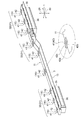
- a vehicle body strength member 2 extending in the vehicle width direction 1 is installed inside the instrument panel.
- substrate is arrange
- this harness substrate is constituted by a long substrate 3 (see FIG. 3) having a length (for example, about 2 m) close to the width dimension of the vehicle.
- two long substrates 3 having a length of about half the width of the vehicle (for example, about 1 m) are connected to each other.
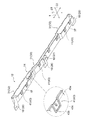
- the long substrate 3 is fixed to the upper portion of the vehicle body strength member 2 together with the substrate case 4 while being accommodated in the substrate case 4.
- the substrate case 4 accommodating the long substrate 3 may be fixed to the lower part, the front part or the rear part of the vehicle body strength member 2.
- the vehicle body strength member 2 described above is called a steering support member or a cross car beam.
- the above-described wire harness is a bundle of electric wires for supplying electric power, signals, and the like to each part of the vehicle body, and the harness substrate is the long substrate 3 in which the wire harness is formed as described above.
- the long substrate 3 is extremely difficult to manufacture and has a large influence of distortion and warpage as compared with a relatively short and small rectangular shape such as a normal substrate.
- the vehicle of this embodiment has the following configuration.
- the long substrate 3 is the harness substrate described above.
- a long substrate 3 is not limited to a harness substrate.
- the long substrate 3 has long side portions (front edge portion and rear edge portion) positioned in the vehicle front-rear direction 22, and both end portions (right end portion and left end portion) positioned in the vehicle width direction 1. Short side.
- the harness board is a long board 3 extending in the vehicle width direction 1 and having a narrow width with respect to the vertical direction 21 with its plate surface (mounting surface) substantially oriented in the vehicle front-rear direction 22. It is also possible. This case is not particularly described in this embodiment, but can be applied by replacing the vertical direction 21 and the vehicle longitudinal direction 22 in the following description.
- the substrate case 4 of this embodiment includes an inner case 11 that can accommodate the long substrate 3 therein and an outer case 12 that can accommodate the inner case 11 together with the long substrate 3.
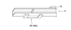
- the inner case 11 has, on one side, a long substrate insertion opening 13 into which the long substrate 3 can be inserted in a direction parallel to the plate surface of the long substrate 3.
- the outer case 12 has an inner case insertion opening 14 on the other side portion through which the inner case 11 can be inserted in a direction parallel to the plate surface of the long substrate 3.
- a substrate sandwiching portion 15 capable of sandwiching and holding the long substrate 3 in the perpendicular direction is provided in the inner case 11.
- a substrate suppressing portion 16 is provided in the outer case 12 to suppress the fluttering in the direction perpendicular to the surface of the long substrate 3.
- the outer case 12 has an external fixing portion 18 that can be fixed to the mounted member 17.
- the attached member 17 will be described later.
- the above-mentioned “one side portion” becomes the front edge portion (front surface portion) or the rear edge portion (rear surface portion) in the vehicle front-rear direction 22, and the “other side portion” becomes the rear edge portion ( It becomes a rear surface portion) or a front edge portion (front surface portion).
- the above-mentioned “direction parallel to the plate surface of the long substrate 3” is the vehicle front-rear direction 22, and “the direction perpendicular to the surface of the long substrate 3” is the vertical direction 21.
- the “direction parallel to the plate surface of the long substrate 3” includes a vehicle width direction 1 and an intermediate (oblique) direction between the vehicle longitudinal direction 22 and the vehicle width direction 1, but these directions are Since the insertion amount becomes long or the structure becomes complicated, the long substrate 3 and the inner case 11 are preferably inserted in the vehicle front-rear direction 22.
- the above-described “inner case 11” extends slightly longer in the vehicle width direction 1 than the long substrate 3, has an opening serving as a long substrate insertion opening 13 on one side, and has a substrate accommodation space inside.
- the member has a substantially C-shaped cross section in side view.
- the inner arm 11 has a C-shaped cross section (a pair of upper and lower sides) and has a length that is about half the width of the long substrate 3. As a result, a substantially half-width portion of the long substrate 3 is accommodated in the inner case 11.
- end face portions that cover at least a part of the C-shaped cross section can be provided as necessary.
- the “outer case 12” extends slightly longer in the vehicle width direction 1 than the inner case 11, has an opening serving as an inner case insertion port 14 on the other side, and accommodates a substrate accommodating space or an inner case inside.
- the inner case insertion port 14 of the outer case 12 is provided to face the long substrate insertion port 13 of the inner case 11.
- the C-shaped (a pair of upper and lower) horizontal arms of the outer case 12 has a length that can accommodate the entire width of the inner case 11. At both ends of the inner case 11, end face portions that cover at least a part of the C-shaped cross section can be provided as necessary.
- the above-mentioned “long board insertion opening 13” extends in the longitudinal direction of the long board 3 (vehicle width direction 1, the same applies hereinafter).
- the long substrate insertion opening 13 has an interval in the vertical direction 21 that is substantially the same as or slightly wider than the thickness of the long substrate 3 so that the long substrate 3 can be inserted.
- the long substrate insertion opening 13 is the sum of the thickness of the long substrate 3 and the height dimension of the substrate sandwiching portion 15.
- the space in the up-down direction 21 is wide by an amount corresponding to.
- the “inner case insertion opening 14” extends in the longitudinal direction of the long substrate 3.
- the inner case insertion opening 14 has an interval (in the vertical direction 21) that is the same as or slightly wider than the thickness of the inner case 11. This interval is such an interval that the inner case 11 can be accommodated with almost no gap.
- the above-described “substrate clamping portion 15” is formed by, for example, a pair of upper and lower press-fitting ribs 25 provided on the inner portion of the inner case 11 having a C-shaped cross section. Composed.
- inclined portions 25 a that are close to each other as they go to the back side are provided at least on the entry side.
- the inclined portion 25a may be linear or (convex) curved.
- parallel portions 25b having an interval substantially equal to or slightly narrower than the plate thickness of the long substrate 3 are provided on the inner side of the press-fitting rib 25 as necessary.
- a plurality of the substrate sandwiching portions 15 are provided along the longitudinal direction of the inner case 11.
- the “substrate restraining portion 16” includes, for example, a pair of (upper and lower) holding ribs 26 provided on the inner portion of the outer case 12 having a C-shaped cross section.
- the portions of the pair of holding ribs 26 that suppress the fluttering of the plate surface of the long substrate 3 are provided with inclined portions 26a that are close to each other as they go to the back side, at least on the entry side.
- the inclined portion 26a may be linear or (convex) curved.
- the back side portion of the holding rib 26 is provided with parallel portions 26b having a slightly wider interval than the above-described parallel portions 25b.
- a plurality of the substrate suppressing portions 16 are provided along the longitudinal direction of the outer case 12.
- the “attached member 17” described above is, for example, the vehicle body strength member 2 described above.
- the substrate case 4 is attached and fixed to the upper part or the lower part (in this case, the upper part) of the vehicle body strength member 2.
- the “external fixing part 18” can be constituted by a pin fixing part 27, a screwing part 28, etc., as shown in the partial enlarged views of FIG. 3 and FIG.
- a pin fixing portion 27 is provided for positioning relative to the central portion of the outer case 12 in the longitudinal direction.
- the pin fixing portion 27 is constituted by a positioning locking pin that extends in a substantially perpendicular direction from the surface (lower surface) of the outer case 12 that contacts the vehicle body strength member 2 toward the vehicle body strength member 2.
- a pin hole (not shown) into which the positioning locking pin is fitted and locked is provided at a corresponding position (a central portion in the longitudinal direction) of the vehicle body strength member 2.
- screw fixing portions 28 are provided for fixing to the center portion and both end portions (three locations) in the longitudinal direction of the outer case 12.
- the screwing portion 28 is configured by an attachment piece having a surface parallel to the long substrate 3 and extending outward from one side portion of the outer case 12.
- the mounting piece is provided with a screw hole for screwing.
- the central screw hole portion is a round hole for position fixing
- the screw hole portions at both ends are long holes extending in the longitudinal direction so as to absorb errors and thermal expansion.
- the above-described substrate sandwiching portion 15 can be provided at an arbitrary position, but is preferably provided at the following position.
- the substrate sandwiching portion 15 is provided at a strain suppression point 31 of the long substrate 3.
- One or a plurality of substrate sandwiching portions 15 can be provided for each distortion suppression point 31.
- the distortion suppression point 31 is the position of the connector mounting portion 32 or the shape changing portion 33 of the long substrate 3.
- the “connector mounting portion 32” is literally a portion where an external connector is mounted on the long substrate 3.
- the long substrate 3 is provided with a connector 35 that can be connected to the external connector on the lower surface side of both end portions.
- the connector mounting portion 32 is not limited to the above, and can be provided at an appropriate position.
- the inner case 11 and the outer case 12 are provided with connector accommodating portions 36 and 37 that can accommodate the connector 35, respectively.
- the connector accommodating portions 36 and 37 have an opening portion for allowing connection of an external connector, and the opening portion is provided toward the vehicle rear side.
- the “shape changing portion 33” is literally a portion where the shape of the long substrate 3 changes.
- the long substrate 3 has an upper and lower step portion as the shape changing portion 33 at a position between the center portion and the end portion.
- This shape change part 33 may be formed according to the shape change part of the upper surface of the to-be-attached member 17, for example.
- a portion where the distance between them becomes long can also be set as the strain suppression point 31 to provide the substrate sandwiching portion 15.
- substrate suppression part 16 in the same position as the board
- substrate suppression part 16 may be provided facing the board
- a case fixing portion 41 is provided between the inner case 11 and the outer case 12 so that both can be fixed at a distortion suppression point 31.
- the “case fixing portion 41” regulates the movement of the inner case 11 in the direction perpendicular to the surface (vertical direction 21) with respect to the outer case 12, and at least slightly moves in the longitudinal direction (vehicle width direction 1). It should be acceptable.
- the case fixing portion 41 described above is an engaging portion including an engaging piece 42 provided on one of the inner case 11 and the outer case 12 and an engaged portion 43 provided on the other.
- the engaging piece 42 and the engaged portion 43 are literally engaged with each other to fix the inner case 11 and the outer case 12.
- the engaging piece 42 is provided on the inner case 11 side and the engaged portion 43 is provided on the outer case 12 side.
- this configuration may be reversed.
- the “engagement piece 42” protrudes from the other side of the inner case 11 toward the upper surface side or the lower surface side.
- the engagement piece 42 has a length substantially equal to the thickness of the inner case insertion port 14 of the outer case 12 and rises substantially in the vertical direction 21, and the upper surface of the outer case 12 from the end of the vertical portion 42 a.
- a parallel portion 42b bent so as to be parallel to each other.
- the parallel portion 42b can be brought into surface contact or pressure contact with the upper surface or the lower surface of the outer case 12.
- the parallel portion 42b may have a trapezoidal shape that is tapered in a plan view so that it can be guided when engaged with the engaged portion 43.
- the “engaged portion 43” is a concave portion that is provided on the upper surface or the lower surface of the other side portion of the outer case 12 and has a shape that substantially matches the engagement piece 42. 43a, or a peripheral wall 43b that surrounds at least a part of the outer periphery of the engagement piece 42.
- the concave portion 43a or the peripheral wall portion 43b has, for example, a trapezoidal shape that is tapered in plan view so that it can substantially match the parallel portion 42b.
- an inner claw portion 43c is provided inside the engaged portion 43 as shown in FIG. 5, and a parallel portion 42b of each engaging piece 42 as shown in FIG.
- a double claw may be formed.
- the case fixing portion 41 is restricted from moving in the direction perpendicular to the inner case 11 with respect to the outer case 12, and at least slightly moved in the longitudinal direction (vehicle width direction 1).
- vehicle width direction 1 there is a gap between the engaging piece 42 and the engaged portion 43 and between the inner claw portion 43c and the inner claw receiving portion 42c with respect to the longitudinal direction.
- Some play gaps 44a and 44b are provided.
- the play gaps 44 a and 44 b may be provided in the vehicle front-rear direction 22 in order to allow slight movement in the vehicle front-rear direction 22.
- a central position defining portion 46 capable of defining the position of the central portion in the longitudinal direction is provided.
- the “center position defining portion 46” is provided on the slide guide 46a provided on the upper surface side inside the outer case 12, and on the lower surface side outside the inner case 11 as shown in FIG. And a guide receiver 46b.
- the slide guide 46a and the guide receiver 46b extend in the insertion direction of the inner case 11 with respect to the outer case 12, and are slidably fitted.
- the shapes of the slide guide 46a and the guide receiver 46b are not limited to those illustrated.
- a longitudinal position restricting portion 47 capable of restricting the longitudinal position of the long substrate 3 with respect to the inner case 11 is provided between the inner case 11 and the long substrate 3. Yes.
- the “longitudinal position restricting portions 47” are provided at a pair of longitudinal position restricting claw portions 48 provided at both ends of the inner case 11 or in the vicinity thereof, and at both ends of the long substrate 3 or in the vicinity thereof.
- the above-mentioned “longitudinal position restricting claw portion 48” extends substantially in parallel with the horizontal arm portion from the vertical connecting portion having a C-shaped cross section of the inner case 11.
- the longitudinal position restricting claw portion 48 is engaged with the long substrate 3 from the upper surface side.
- the “longitudinal position restricting claw receiving portion 49” is, for example, one of which is a round hole for position fixing and the other is a long hole or a long hole extending in the longitudinal direction so as to absorb errors and thermal expansion. It is a hole-shaped notch.
- the round hole, the long hole, and the like are provided in the center of the width of the long substrate 3.
- the structure of the substrate case 4 described above can be widely applied to the long substrate 3 other than the harness substrate.
- the long substrate 3 is accommodated in the outer case 12 while being accommodated in the inner case 11.
- the long substrate 3 is inserted from the other side into the long substrate insertion port 13 on one side of the inner case 11 in a direction parallel to the plate surface of the long substrate 3. Further, the inner case 11 containing the long substrate 3 is inserted from one side into the inner case insertion port 14 on the other side of the outer case 12 in a direction parallel to the plate surface of the long substrate 3. .
- the long substrate 3 accommodated in the inner case 11 is held (or crimped) in a direction perpendicular to the surface by a substrate holding portion 15 provided inside the inner case 11. Further, the long substrate 3 accommodated in the outer case 12 together with the inner case 11 is suppressed to the extent that it does not flutter in the perpendicular direction by the substrate suppressing portion 16 provided inside the outer case 12. As described above, by using the inner side of the outer case 12 as the substrate suppressing portion 16, it is possible to suppress the long substrate 3 and make it difficult to transmit influences such as vibration from the outside to the long substrate 3.
- the outer case 12 is fixed to the attached member 17 by the external fixing portion 18.
- the substrate case 4 is divided into one side and the other side (in the case of the vehicle longitudinal direction 22 in this embodiment), and the substrate sandwiching portion 15 and the substrate are separated. Since the long substrate 3 is constrained in the perpendicular direction by the restraining portion 16, the distortion of the long substrate 3 can be effectively suppressed simply by attaching the substrate case 4 to the long substrate 3. In addition, it is not necessary to use a large number of fastening members, and it is not necessary to manage the amount of warping with respect to the long substrate 3 due to the fastening amount of the fastening members during assembly. As a result, it is possible to greatly reduce the assembly man-hours and the part costs.
- the substrate sandwiching portion 15 is provided at the strain suppression point 31 of the long substrate 3, the substrate sandwiching portion 15 can efficiently suppress the strain of the long substrate 3.
- the inner case 11 and the outer case 12 are engaged and fixed by a case fixing portion 41. Then, by providing the case fixing portion 41 at the strain suppression point 31, it is possible to more effectively suppress the distortion of the long substrate 3.
- the engagement piece 42 is provided on one of the inner case 11 and the outer case 12 and the engaged portion 43 is provided on the other, the inner case 11 can be inserted into the outer case 12 with a single touch.
- the outer case 12 can be engaged and fixed easily and reliably.
- the longitudinal position of the long substrate 3 relative to the inner case 11 can be reliably regulated by the longitudinal position restricting portion 47 provided between the inner case 11 and the long substrate 3.
Landscapes
- Engineering & Computer Science (AREA)
- Microelectronics & Electronic Packaging (AREA)
- Mechanical Engineering (AREA)
- Casings For Electric Apparatus (AREA)
- Mounting Of Printed Circuit Boards And The Like (AREA)
- Connection Or Junction Boxes (AREA)
- Connector Housings Or Holding Contact Members (AREA)
Abstract
A substrate case (4) is equipped with an inner case (11) capable of housing an elongated substrate (3), and an outer case (12) capable of housing the inner case (11). On one side of the inner case (11) there is an elongated substrate insertion hole (13) in which the elongated substrate (3) can be inserted, and on the other side of the outer case (12) there is an inner case insertion hole (14) in which the inner case (11) can be inserted. Substrate clamping parts (15) capable of clamping and holding the elongated substrate (3) are provided in the interior of the inner case (11). Substrate-restraining parts (16) which prevent the flopping around of the elongated substrate (3) are provided in the interior of the outer case (12), and the outer case (12) has external anchoring parts (18) which can be anchored to attachment subject members (17).
Description
この発明は、基板ケース構造に関するものである。
This invention relates to a substrate case structure.
自動車などの車両には、車室内の前部にインストルメントパネルが設置されている。このインストルメントパネルの内部には、車幅方向へ延びる車体強度部材が設置されている。そして、この車体強度部材に沿ってワイヤーハーネスが取付けられている。
In vehicles such as automobiles, an instrument panel is installed in the front of the passenger compartment. A vehicle body strength member extending in the vehicle width direction is installed inside the instrument panel. A wire harness is attached along the vehicle body strength member.
上記した車体強度部材は、ステアリングサポートメンバまたはクロスカービームなどと呼ばれるものである。また上記したワイヤーハーネスは、車体の各部に電力や信号などを供給するための電線の束である。
The above-mentioned body strength member is called a steering support member or a cross car beam. The wire harness described above is a bundle of electric wires for supplying electric power, signals, and the like to each part of the vehicle body.
近年、車両の電子化の促進や電装部品の増加などに伴い、ワイヤーハーネスがより太く且つより重いものとなりつつある。そのため、軽量化や高機能化などを目的として、ワイヤーハーネスを電子基板化することが進められている。この基板(いわゆるハーネス基板)は、板面を上下方向へ向けた状態で車体強度部材に沿って延びる長尺のものとされる(長尺基板)と共に、基板ケースに収容された状態で車体強度部材に取付けられる(例えば、特許文献1参照)。
In recent years, wire harnesses are becoming thicker and heavier with the promotion of computerization of vehicles and the increase of electrical components. Therefore, for the purpose of weight reduction and high functionality, the wire harness is being made into an electronic substrate. This board (a so-called harness board) is a long board (long board) that extends along the vehicle body strength member with the plate surface facing in the vertical direction (long board) and the vehicle body strength in a state of being accommodated in the board case. It is attached to a member (for example, refer patent document 1).
従来の基板ケースは、長尺基板の上面と下面とに対してアッパケースとロアケースとを上下から挟むように取付けると共に、アッパケースとロアケースとの間をボルト・ナットなどの締結部材を用いて上下方向に締結するものとされていた。
The conventional board case is mounted so that the upper case and the lower case are sandwiched from above and below the upper and lower surfaces of the long board, and between the upper case and the lower case by using fastening members such as bolts and nuts. It was supposed to be fastened in the direction.
しかしながら、従来の基板ケースには、以下のような問題があった。
However, the conventional substrate case has the following problems.
即ち、基板ケースを、アッパケースとロアケースとに上下分割して、長尺基板を上下から挟むように取付ける構造としていたため、アッパケースおよびロアケースの長尺基板に対する取付面の面積が大きくなっていた。そのため、長尺基板の歪みを抑えるように取付けるのに、締結部材の取付箇所が多くなると共に、締結部材の取付時に基板の反り量などについても厳密に寸法管理を行わなければならなかった。
That is, since the board case is divided into an upper case and a lower case so that the long board is sandwiched from above and below, the area of the mounting surface of the upper case and the lower case with respect to the long board is large. . For this reason, in order to suppress the distortion of the long substrate, the number of places where the fastening members are attached increases, and the amount of warpage of the substrate must be strictly controlled when attaching the fastening members.
上記課題を解決するために、本発明の基板ケース構造は、長尺基板を内部へ収容可能なインナケースと、前記インナケースを前記長尺基板ごと内部へ収容可能なアウタケースと、を備え、前記インナケースは、一側部に、前記長尺基板を前記長尺基板の板面と平行な方向へ挿入可能な長尺基板挿入口を有し、前記アウタケースは、他側部に、前記インナケースを前記長尺基板の板面と平行な方向へ挿入可能なインナケース挿入口を有し、前記インナケースの内部には、前記長尺基板を面直方向に挟着保持可能な基板挟着部が設けられ、前記アウタケースの内部には、前記長尺基板の面直方向に対するバタ付きを抑える基板抑制部が設けられ、前記アウタケースは、被取付部材に対して固定可能な外部固定部を有することを特徴とする。
In order to solve the above problems, the substrate case structure of the present invention includes an inner case capable of accommodating a long substrate therein, and an outer case capable of accommodating the inner case together with the long substrate, The inner case has a long substrate insertion port into which one side portion can insert the long substrate in a direction parallel to the plate surface of the long substrate, and the outer case has the other side portion, The inner case has an inner case insertion slot into which the inner case can be inserted in a direction parallel to the plate surface of the long substrate, and the inner case has a substrate holding member that can hold the long substrate in a perpendicular direction. A mounting portion is provided, and a substrate restraining portion is provided inside the outer case to suppress fluttering in a direction perpendicular to the surface of the long substrate, and the outer case is externally fixed to be fixed to a mounted member. It has the part.
以下、本発明を具体化した実施例を、図面を用いて詳細に説明する。
Hereinafter, embodiments embodying the present invention will be described in detail with reference to the drawings.
図1~図10は、この実施例およびその変形例を示すものである。
1 to 10 show this embodiment and its modifications.
<構成>以下、構成について説明する。
<Configuration> The configuration will be described below.
自動車などの車両には、車室内の前部にインストルメントパネルが設置されている。このインストルメントパネルの内部には、図1の全体斜視図に示すように、車幅方向1へ延びる車体強度部材2が設置されている。そして、この車体強度部材2に沿っていわゆるワイヤーハーネスを基板化してなるハーネス基板が配設される。このハーネス基板は、図2の組立図および図3の分解斜視図から分かるように、車両の幅寸法に近い長さ(例えば、約2m)を有する長尺基板3(図3参照)により構成される。或いは、特に図示しないが、車両の半幅程度の長さ(例えば、約1m)の長尺基板3を2枚連結して構成される。長尺基板3は、基板ケース4に収容された状態で基板ケース4ごと車体強度部材2の上部に固定される。なお、車両の構造によっては、長尺基板3を収容した基板ケース4は、車体強度部材2の下部や前部または後部に固定されていても良い。
In vehicles such as automobiles, an instrument panel is installed in the front of the passenger compartment. As shown in the overall perspective view of FIG. 1, a vehicle body strength member 2 extending in the vehicle width direction 1 is installed inside the instrument panel. And along this vehicle body strength member 2, the harness board | substrate formed by making what is called a wire harness into a board | substrate is arrange | positioned. As can be seen from the assembly diagram of FIG. 2 and the exploded perspective view of FIG. 3, this harness substrate is constituted by a long substrate 3 (see FIG. 3) having a length (for example, about 2 m) close to the width dimension of the vehicle. The Alternatively, although not particularly illustrated, two long substrates 3 having a length of about half the width of the vehicle (for example, about 1 m) are connected to each other. The long substrate 3 is fixed to the upper portion of the vehicle body strength member 2 together with the substrate case 4 while being accommodated in the substrate case 4. Depending on the structure of the vehicle, the substrate case 4 accommodating the long substrate 3 may be fixed to the lower part, the front part or the rear part of the vehicle body strength member 2.
上記した車体強度部材2は、ステアリングサポートメンバまたはクロスカービームなどと呼ばれるものである。また上記したワイヤーハーネスは、車体の各部に電力や信号などを供給するための電線の束であり、ハーネス基板は、上記したようにワイヤーハーネスを基板化した長尺基板3である。この長尺基板3は、通常の基板のような比較的短くて小さな矩形状などのものと比べて、製造が極めて難しく、また、歪や反りの影響が大きい。
The vehicle body strength member 2 described above is called a steering support member or a cross car beam. Moreover, the above-described wire harness is a bundle of electric wires for supplying electric power, signals, and the like to each part of the vehicle body, and the harness substrate is the long substrate 3 in which the wire harness is formed as described above. The long substrate 3 is extremely difficult to manufacture and has a large influence of distortion and warpage as compared with a relatively short and small rectangular shape such as a normal substrate.
以上のような基本的な構成に対し、この実施例の車両では、以下のような構成を備えている。
In contrast to the basic configuration as described above, the vehicle of this embodiment has the following configuration.
なお、以下の実施例では、長尺基板3が、上記したハーネス基板である場合について説明する。但し、このような長尺基板3は、ハーネス基板に限るものではない。
In the following embodiments, the case where the long substrate 3 is the harness substrate described above will be described. However, such a long substrate 3 is not limited to a harness substrate.
そして、このハーネス基板を、その板面(実装面)がほぼ上下方向21へ向いた状態で、車幅方向1に延設される、車両前後方向22に対して狭幅の長尺基板3とする。これにより、この長尺基板3は、車両前後方向22に位置する両側部(前縁部および後縁部)が長辺となり、車幅方向1に位置する両端部(右端部および左端部)が短辺となる。
And this harness board | substrate is extended in the vehicle width direction 1 in the state in which the plate | board surface (mounting surface) has faced the up-down direction 21, and the elongate board | substrate 3 narrow with respect to the vehicle front-back direction 22 and To do. As a result, the long substrate 3 has long side portions (front edge portion and rear edge portion) positioned in the vehicle front-rear direction 22, and both end portions (right end portion and left end portion) positioned in the vehicle width direction 1. Short side.
なお、ハーネス基板は、その板面(実装面)がほぼ車両前後方向22へ向いた状態で、車幅方向1に延設される、上下方向21に対して狭幅の長尺基板3とすることも可能である。この場合については、この実施例では特に説明しないが、以下の説明の上下方向21と車両前後方向22とを読み替えて適用することができる。
The harness board is a long board 3 extending in the vehicle width direction 1 and having a narrow width with respect to the vertical direction 21 with its plate surface (mounting surface) substantially oriented in the vehicle front-rear direction 22. It is also possible. This case is not particularly described in this embodiment, but can be applied by replacing the vertical direction 21 and the vehicle longitudinal direction 22 in the following description.
この実施例の基板ケース4は、長尺基板3を内部へ収容可能なインナケース11と、インナケース11を長尺基板3ごと内部へ収容可能なアウタケース12とを備えている。
The substrate case 4 of this embodiment includes an inner case 11 that can accommodate the long substrate 3 therein and an outer case 12 that can accommodate the inner case 11 together with the long substrate 3.
図4に示すように、インナケース11が、一側部に、長尺基板3を長尺基板3の板面と平行な方向へ挿入可能な長尺基板挿入口13を有する。また、図5に示すように、アウタケース12が、他側部に、インナケース11を長尺基板3の板面と平行な方向へ挿入可能なインナケース挿入口14を有する。
As shown in FIG. 4, the inner case 11 has, on one side, a long substrate insertion opening 13 into which the long substrate 3 can be inserted in a direction parallel to the plate surface of the long substrate 3. Further, as shown in FIG. 5, the outer case 12 has an inner case insertion opening 14 on the other side portion through which the inner case 11 can be inserted in a direction parallel to the plate surface of the long substrate 3.
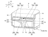
更に、図6の断面図に示すように、インナケース11の内部には、長尺基板3を面直方向に挟着保持可能な基板挟着部15が設けられている。また、アウタケース12の内部には、長尺基板3の面直方向に対するバタ付きを抑える基板抑制部16が設けられている。
Furthermore, as shown in the cross-sectional view of FIG. 6, a substrate sandwiching portion 15 capable of sandwiching and holding the long substrate 3 in the perpendicular direction is provided in the inner case 11. In addition, a substrate suppressing portion 16 is provided in the outer case 12 to suppress the fluttering in the direction perpendicular to the surface of the long substrate 3.
そして、図2に示すように、アウタケース12が、被取付部材17に対して固定可能な外部固定部18を有する。被取付部材17については、後述する。
2, the outer case 12 has an external fixing portion 18 that can be fixed to the mounted member 17. The attached member 17 will be described later.
以下、上記についての補足説明を行う。但し、以下の補足説明は、単なる例示であり、必ずしもこれに限定されるものではない(以下、同様)。
The following is a supplementary explanation of the above. However, the following supplementary explanation is merely an example, and the present invention is not necessarily limited to this (the same applies hereinafter).
この場合、上記した「一側部」が、車両前後方向22の前縁部(前面部)または後縁部(後面部)となり、「他側部」が、車両前後方向22の後縁部(後面部)または前縁部(前面部)となる。また、上記した「長尺基板3の板面と平行な方向」が、車両前後方向22となり、「長尺基板3の面直方向」が上下方向21となる。なお、「長尺基板3の板面と平行な方向」には、車幅方向1や、車両前後方向22と車幅方向1との中間の(斜め)方向も含まれるが、これらの方向は、挿入量が長くなる、或いは、構造が複雑になるため、長尺基板3やインナケース11は車両前後方向22へ挿入されることが好ましい。
In this case, the above-mentioned “one side portion” becomes the front edge portion (front surface portion) or the rear edge portion (rear surface portion) in the vehicle front-rear direction 22, and the “other side portion” becomes the rear edge portion ( It becomes a rear surface portion) or a front edge portion (front surface portion). Further, the above-mentioned “direction parallel to the plate surface of the long substrate 3” is the vehicle front-rear direction 22, and “the direction perpendicular to the surface of the long substrate 3” is the vertical direction 21. The “direction parallel to the plate surface of the long substrate 3” includes a vehicle width direction 1 and an intermediate (oblique) direction between the vehicle longitudinal direction 22 and the vehicle width direction 1, but these directions are Since the insertion amount becomes long or the structure becomes complicated, the long substrate 3 and the inner case 11 are preferably inserted in the vehicle front-rear direction 22.
そして、上記した「インナケース11」は、長尺基板3よりも車幅方向1へ若干長く延びて、一側部に長尺基板挿入口13となる開口部を有すると共に内部に基板収容空間を有する側面視ほぼC字断面の部材とされる。インナケース11の断面C字状をした(上下一対の)横腕部は、長尺基板3の幅寸法の半分程度の長さを有する。これにより、長尺基板3のほぼ半幅の部分がインナケース11に収容される。インナケース11の両端部には、必要に応じて、C字状の断面の少なくとも一部を覆う端面部を設けることができる。
The above-described “inner case 11” extends slightly longer in the vehicle width direction 1 than the long substrate 3, has an opening serving as a long substrate insertion opening 13 on one side, and has a substrate accommodation space inside. The member has a substantially C-shaped cross section in side view. The inner arm 11 has a C-shaped cross section (a pair of upper and lower sides) and has a length that is about half the width of the long substrate 3. As a result, a substantially half-width portion of the long substrate 3 is accommodated in the inner case 11. At both ends of the inner case 11, end face portions that cover at least a part of the C-shaped cross section can be provided as necessary.
また、「アウタケース12」は、インナケース11よりも車幅方向1へ若干長く延びて、他側部にインナケース挿入口14となる開口部を有すると共に、内部に基板収容空間またはインナケース収容空間を有する側面視ほぼC字断面の部材とされる。アウタケース12のインナケース挿入口14は、インナケース11の長尺基板挿入口13と対向するように設けられている。アウタケース12のC字状の(上下一対の)横腕部は、インナケース11の全幅を収容可能な長さを有するものとされる。インナケース11の両端部には、必要に応じて、C字状の断面の少なくとも一部を覆う端面部を設けることができる。
Further, the “outer case 12” extends slightly longer in the vehicle width direction 1 than the inner case 11, has an opening serving as an inner case insertion port 14 on the other side, and accommodates a substrate accommodating space or an inner case inside. A member having a space and a substantially C-shaped cross section in a side view. The inner case insertion port 14 of the outer case 12 is provided to face the long substrate insertion port 13 of the inner case 11. The C-shaped (a pair of upper and lower) horizontal arms of the outer case 12 has a length that can accommodate the entire width of the inner case 11. At both ends of the inner case 11, end face portions that cover at least a part of the C-shaped cross section can be provided as necessary.
上記した「長尺基板挿入口13」は、長尺基板3の長手方向(車幅方向1、以下同様)へ延びている。長尺基板挿入口13は、長尺基板3を挿入可能なように、長尺基板3の厚みとほぼ同じかそれよりも若干広い上下方向21の間隔を有している。この場合には、インナケース11の内部に基板挟着部15が設けられるので、長尺基板挿入口13は、長尺基板3の厚みと基板挟着部15の高さ方向の寸法との和に相当する分だけ広い上下方向21の間隔を有している。
The above-mentioned “long board insertion opening 13” extends in the longitudinal direction of the long board 3 (vehicle width direction 1, the same applies hereinafter). The long substrate insertion opening 13 has an interval in the vertical direction 21 that is substantially the same as or slightly wider than the thickness of the long substrate 3 so that the long substrate 3 can be inserted. In this case, since the substrate sandwiching portion 15 is provided inside the inner case 11, the long substrate insertion opening 13 is the sum of the thickness of the long substrate 3 and the height dimension of the substrate sandwiching portion 15. The space in the up-down direction 21 is wide by an amount corresponding to.
また、「インナケース挿入口14」は、長尺基板3の長手方向へ延びている。インナケース挿入口14は、インナケース11の厚みと同じかそれよりも若干広い(上下方向21の)間隔を有している。この間隔は、インナケース11をほぼ隙間無く収容し得る程度の間隔である。
Further, the “inner case insertion opening 14” extends in the longitudinal direction of the long substrate 3. The inner case insertion opening 14 has an interval (in the vertical direction 21) that is the same as or slightly wider than the thickness of the inner case 11. This interval is such an interval that the inner case 11 can be accommodated with almost no gap.
上記した「基板挟着部15」は、図6、図7の断面図に示すように、例えば、インナケース11の断面C字状の内側部分に設けられた(上下)一対の圧入リブ25により構成される。この一対の圧入リブ25における、長尺基板3の板面を挟着する部分には、少なくとも入側の部分に、奥側へ進むに従って互いに近接する傾斜部25aが設けられている。この傾斜部25aは、直線状や(凸型の)曲線状のものなどとすることができる。また、必要に応じて、圧入リブ25における奥側の部分には、長尺基板3の板厚とほぼ等しいか若干狭い間隔の平行部25bが設けられる。この基板挟着部15は、インナケース11の長手方向に沿って複数設けられる。
As shown in the cross-sectional views of FIGS. 6 and 7, the above-described “substrate clamping portion 15” is formed by, for example, a pair of upper and lower press-fitting ribs 25 provided on the inner portion of the inner case 11 having a C-shaped cross section. Composed. In the portion of the pair of press-fitting ribs 25 that sandwich the plate surface of the long substrate 3, inclined portions 25 a that are close to each other as they go to the back side are provided at least on the entry side. The inclined portion 25a may be linear or (convex) curved. In addition, parallel portions 25b having an interval substantially equal to or slightly narrower than the plate thickness of the long substrate 3 are provided on the inner side of the press-fitting rib 25 as necessary. A plurality of the substrate sandwiching portions 15 are provided along the longitudinal direction of the inner case 11.
また、「基板抑制部16」は、図6に示すように、例えば、アウタケース12の断面C字状の内側部分設けられた(上下)一対の抑えリブ26により構成される。この一対の抑えリブ26における、長尺基板3の板面のバタ付きを抑える部分には、少なくとも入側の部分に、奥側へ進むに従って互いに近接する傾斜部26aが設けられている。この傾斜部26aは、直線状や(凸型の)曲線状のものなどとすることができる。また、必要に応じて、抑えリブ26における奥側の部分は、上記した平行部25bよりも若干広い間隔の平行部26bが設けられる。この基板抑制部16は、アウタケース12の長手方向に沿って複数設けられる。
Further, as shown in FIG. 6, the “substrate restraining portion 16” includes, for example, a pair of (upper and lower) holding ribs 26 provided on the inner portion of the outer case 12 having a C-shaped cross section. The portions of the pair of holding ribs 26 that suppress the fluttering of the plate surface of the long substrate 3 are provided with inclined portions 26a that are close to each other as they go to the back side, at least on the entry side. The inclined portion 26a may be linear or (convex) curved. Further, if necessary, the back side portion of the holding rib 26 is provided with parallel portions 26b having a slightly wider interval than the above-described parallel portions 25b. A plurality of the substrate suppressing portions 16 are provided along the longitudinal direction of the outer case 12.
上記した「被取付部材17」は、例えば、上記した車体強度部材2とされる。基板ケース4は、車体強度部材2の上部または下部(この場合には、上部)に対して取付固定される。
The “attached member 17” described above is, for example, the vehicle body strength member 2 described above. The substrate case 4 is attached and fixed to the upper part or the lower part (in this case, the upper part) of the vehicle body strength member 2.
また、「外部固定部18」は、図3、および、図8の部分拡大図に示すように、ピン固定部27やネジ止部28などにより構成することができる。この場合、アウタケース12の長手方向の中央部に対して位置決用にピン固定部27が設けられる。このピン固定部27は、アウタケース12の車体強度部材2と接する面(下面)から車体強度部材2へ向けてほぼ面直方向へ延びる位置決用係止ピンにより構成される。これに対し、車体強度部材2の対応する位置(長手方向の中央部)には、位置決用係止ピンが嵌合係止される図示しないピン穴が設けられる。また、アウタケース12の長手方向の中央部および両端部(の3箇所)に対して固定用にネジ止部28が設けられる。このネジ止部28は、アウタケース12の一側部からそれぞれ外方へ向かって張出形成された、長尺基板3と平行な面を有する取付片により構成される。この取付片には、ネジ止用のネジ孔部が設けられている。このうち、例えば、中央のネジ孔部は位置固定用に丸孔とされ、両端のネジ孔部は誤差や熱膨張を吸収可能なように長手方向へ延びる長孔とされている。
Further, the “external fixing part 18” can be constituted by a pin fixing part 27, a screwing part 28, etc., as shown in the partial enlarged views of FIG. 3 and FIG. In this case, a pin fixing portion 27 is provided for positioning relative to the central portion of the outer case 12 in the longitudinal direction. The pin fixing portion 27 is constituted by a positioning locking pin that extends in a substantially perpendicular direction from the surface (lower surface) of the outer case 12 that contacts the vehicle body strength member 2 toward the vehicle body strength member 2. On the other hand, a pin hole (not shown) into which the positioning locking pin is fitted and locked is provided at a corresponding position (a central portion in the longitudinal direction) of the vehicle body strength member 2. In addition, screw fixing portions 28 are provided for fixing to the center portion and both end portions (three locations) in the longitudinal direction of the outer case 12. The screwing portion 28 is configured by an attachment piece having a surface parallel to the long substrate 3 and extending outward from one side portion of the outer case 12. The mounting piece is provided with a screw hole for screwing. Among these, for example, the central screw hole portion is a round hole for position fixing, and the screw hole portions at both ends are long holes extending in the longitudinal direction so as to absorb errors and thermal expansion.
上記した基板挟着部15は、任意の位置に設けることができるが、好ましくは、以下の位置に設けるようにする。
The above-described substrate sandwiching portion 15 can be provided at an arbitrary position, but is preferably provided at the following position.
図4、図7に示すように、基板挟着部15は、長尺基板3の歪抑制ポイント31に設けられている。
As shown in FIGS. 4 and 7, the substrate sandwiching portion 15 is provided at a strain suppression point 31 of the long substrate 3.
基板挟着部15は、各歪抑制ポイント31につき、1個または複数個設けることができる。
One or a plurality of substrate sandwiching portions 15 can be provided for each distortion suppression point 31.
歪抑制ポイント31は、長尺基板3のコネクタ装着部32または形状変化部33の位置とされる。
The distortion suppression point 31 is the position of the connector mounting portion 32 or the shape changing portion 33 of the long substrate 3.
「コネクタ装着部32」は、文字通り、長尺基板3に対して外部のコネクタを装着する部分のことである。この場合、長尺基板3には、両端部の下面側に上記外部のコネクタと接続可能なコネクタ35が設けられている。但し、コネクタ装着部32は、上記に限ることなく、適宜位置に設けることができる。
The “connector mounting portion 32” is literally a portion where an external connector is mounted on the long substrate 3. In this case, the long substrate 3 is provided with a connector 35 that can be connected to the external connector on the lower surface side of both end portions. However, the connector mounting portion 32 is not limited to the above, and can be provided at an appropriate position.
これに対し、インナケース11およびアウタケース12には、このコネクタ35を収容可能なコネクタ収容部36,37がそれぞれ設けられている。このコネクタ収容部36,37は、外部のコネクタを接続し得るようにするための開口部分を有しており、開口部分は車両後方側へ向けて設けられている。
On the other hand, the inner case 11 and the outer case 12 are provided with connector accommodating portions 36 and 37 that can accommodate the connector 35, respectively. The connector accommodating portions 36 and 37 have an opening portion for allowing connection of an external connector, and the opening portion is provided toward the vehicle rear side.
「形状変化部33」は、文字通り、長尺基板3の形状が変化する部分のことである。長尺基板3は、中央部と端部との間の位置に、形状変化部33としての上下段差部を有している。この形状変化部33は、例えば、被取付部材17の上面の形状変化部分に応じて形成されていても良い。
The “shape changing portion 33” is literally a portion where the shape of the long substrate 3 changes. The long substrate 3 has an upper and lower step portion as the shape changing portion 33 at a position between the center portion and the end portion. This shape change part 33 may be formed according to the shape change part of the upper surface of the to-be-attached member 17, for example.
更に、相互間の距離が長くなる部分(いわゆるロングスパン部分)なども歪抑制ポイント31に設定して、基板挟着部15を設けることができる。なお、これら以外の位置に、基板挟着部15を設けるようにしても良い。
Furthermore, a portion where the distance between them becomes long (so-called long span portion) or the like can also be set as the strain suppression point 31 to provide the substrate sandwiching portion 15. In addition, you may make it provide the board | substrate clamping part 15 in positions other than these.
なお、基板抑制部16についても、基板挟着部15と同じ位置に設けるようにするのが好ましい。たとえば、基板抑制部16は、基板挟着部15と対向させて設けられていても良い。
In addition, it is preferable to provide the board | substrate suppression part 16 in the same position as the board | substrate clamping part 15. FIG. For example, the board | substrate suppression part 16 may be provided facing the board | substrate clamping part 15. FIG.
主に図2に示すように、インナケース11とアウタケース12との間に、歪抑制ポイント31にて両者を固定可能なケース固定部41が設けられている。
As shown mainly in FIG. 2, a case fixing portion 41 is provided between the inner case 11 and the outer case 12 so that both can be fixed at a distortion suppression point 31.
「ケース固定部41」は、アウタケース12に対して、インナケース11の面直方向(上下方向21)への移動を規制すると共に、少なくとも長手方向(車幅方向1)への若干の移動を許容し得るようなものとする。
The “case fixing portion 41” regulates the movement of the inner case 11 in the direction perpendicular to the surface (vertical direction 21) with respect to the outer case 12, and at least slightly moves in the longitudinal direction (vehicle width direction 1). It should be acceptable.
上記したケース固定部41は、インナケース11とアウタケース12との一方に設けられた係合片42および他方に設けられた被係合部43からなる係合部とする。
The case fixing portion 41 described above is an engaging portion including an engaging piece 42 provided on one of the inner case 11 and the outer case 12 and an engaged portion 43 provided on the other.
係合片42と被係合部43とは、文字通り、互いに係合することによって、インナケース11とアウタケース12とを固定するものである。この場合、インナケース11の側に係合片42が設けられていると共に、アウタケース12の側に被係合部43が設けられているが、この構成は逆であっても良い。
The engaging piece 42 and the engaged portion 43 are literally engaged with each other to fix the inner case 11 and the outer case 12. In this case, the engaging piece 42 is provided on the inner case 11 side and the engaged portion 43 is provided on the outer case 12 side. However, this configuration may be reversed.
上記「係合片42」は、図4に示すように、インナケース11の他側部から、上面側または下面側へ向けて突設されている。この係合片42は、アウタケース12のインナケース挿入口14の厚みとほぼ等しい長さで、ほぼ上下方向21へ立上がる立上部42aと、この立上部42aの端部からアウタケース12の上面と平行となるように屈曲された平行部42bとを有している。この平行部42bは、アウタケース12の上面または下面に対して面接触或いは圧接可能なものである。この平行部42bは、被係合部43に対して係合する際に、案内が可能なように、例えば平面視先細りの台形状としても良い。
As shown in FIG. 4, the “engagement piece 42” protrudes from the other side of the inner case 11 toward the upper surface side or the lower surface side. The engagement piece 42 has a length substantially equal to the thickness of the inner case insertion port 14 of the outer case 12 and rises substantially in the vertical direction 21, and the upper surface of the outer case 12 from the end of the vertical portion 42 a. And a parallel portion 42b bent so as to be parallel to each other. The parallel portion 42b can be brought into surface contact or pressure contact with the upper surface or the lower surface of the outer case 12. For example, the parallel portion 42b may have a trapezoidal shape that is tapered in a plan view so that it can be guided when engaged with the engaged portion 43.
これに対し、上記「被係合部43」は、図5に示すように、アウタケース12の他側部の上面または下面に対して設けられた、係合片42とほぼ合致する形状の凹部43a、または、係合片42の少なくとも一部の外周を囲う周壁部43bなどにより構成されている。この凹部43aまたは周壁部43bは、平行部42bとほぼ合致し得るようにするために、例えば平面視先細りの台形状とされている。
On the other hand, as shown in FIG. 5, the “engaged portion 43” is a concave portion that is provided on the upper surface or the lower surface of the other side portion of the outer case 12 and has a shape that substantially matches the engagement piece 42. 43a, or a peripheral wall 43b that surrounds at least a part of the outer periphery of the engagement piece 42. The concave portion 43a or the peripheral wall portion 43b has, for example, a trapezoidal shape that is tapered in plan view so that it can substantially match the parallel portion 42b.
更に、必要な場合には、図5に示すように、上記した被係合部43の内部に内爪部43cを設け、図4に示すように、上記した各係合片42の平行部42bの内部に孔状の内爪受部42cを設けることにより、二重爪となるようにしても良い。
Further, if necessary, an inner claw portion 43c is provided inside the engaged portion 43 as shown in FIG. 5, and a parallel portion 42b of each engaging piece 42 as shown in FIG. By providing a hole-like inner claw receiving portion 42c in the inside, a double claw may be formed.
そして、上記したように、ケース固定部41を、アウタケース12に対して、インナケース11の面直方向への移動を規制すると共に、少なくとも長手方向(車幅方向1)への若干の移動を許容し得るものとするために、図2に示すように、係合片42と被係合部43との間や、内爪部43cと内爪受部42cとの間には、長手方向に対する若干の遊び隙間44a,44bが設けられている。なお、この遊び隙間44a,44bは、車両前後方向22への若干の移動を許容し得るものとするために、車両前後方向22に対して設けるようにしても良い。
As described above, the case fixing portion 41 is restricted from moving in the direction perpendicular to the inner case 11 with respect to the outer case 12, and at least slightly moved in the longitudinal direction (vehicle width direction 1). In order to be acceptable, as shown in FIG. 2, there is a gap between the engaging piece 42 and the engaged portion 43 and between the inner claw portion 43c and the inner claw receiving portion 42c with respect to the longitudinal direction. Some play gaps 44a and 44b are provided. The play gaps 44 a and 44 b may be provided in the vehicle front-rear direction 22 in order to allow slight movement in the vehicle front-rear direction 22.
加えて、インナケース11とアウタケース12との間には、長手方向の中央部の位置を規定可能な中央位置規定部46が設けられている。
In addition, between the inner case 11 and the outer case 12, a central position defining portion 46 capable of defining the position of the central portion in the longitudinal direction is provided.
この「中央位置規定部46」は、図8に示すように、アウタケース12内部の上面側に設けられたスライドガイド46aと、図9に示すように、インナケース11外部の下面側に設けられたガイド受46bとを備えている。スライドガイド46aとガイド受46bとは、アウタケース12に対するインナケース11の挿入方向へ延びると共に、摺動可能に嵌合されている。スライドガイド46aと、ガイド受46bとの形状は、図示のものに限るものではない。
As shown in FIG. 8, the “center position defining portion 46” is provided on the slide guide 46a provided on the upper surface side inside the outer case 12, and on the lower surface side outside the inner case 11 as shown in FIG. And a guide receiver 46b. The slide guide 46a and the guide receiver 46b extend in the insertion direction of the inner case 11 with respect to the outer case 12, and are slidably fitted. The shapes of the slide guide 46a and the guide receiver 46b are not limited to those illustrated.
図10の断面図に示すように、インナケース11と長尺基板3との間に、インナケース11に対する長尺基板3の長手方向の位置を規制可能な長手方向位置規制部47が設けられている。
As shown in the sectional view of FIG. 10, a longitudinal position restricting portion 47 capable of restricting the longitudinal position of the long substrate 3 with respect to the inner case 11 is provided between the inner case 11 and the long substrate 3. Yes.
この「長手方向位置規制部47」は、インナケース11の両端部またはその近傍の内部に設けられた一対の長手方向位置規制用爪部48と、長尺基板3の両端部またはその近傍に設けられた一対の長手方向位置規制用爪受部49などにより構成される。
The “longitudinal position restricting portions 47” are provided at a pair of longitudinal position restricting claw portions 48 provided at both ends of the inner case 11 or in the vicinity thereof, and at both ends of the long substrate 3 or in the vicinity thereof. A pair of longitudinal direction position restricting claw receiving portions 49 and the like.
上記した「長手方向位置規制用爪部48」は、インナケース11の断面C字状の縦連結部から横腕部とほぼ平行に延びている。この長手方向位置規制用爪部48は、長尺基板3に対して上面側から係止する。
The above-mentioned “longitudinal position restricting claw portion 48” extends substantially in parallel with the horizontal arm portion from the vertical connecting portion having a C-shaped cross section of the inner case 11. The longitudinal position restricting claw portion 48 is engaged with the long substrate 3 from the upper surface side.
また、「長手方向位置規制用爪受部49」は、例えば、一方が位置固定用に丸孔となっており、他方が誤差や熱膨張を吸収可能なように長手方向へ延びる長孔または長孔状の切欠部となっている。この丸孔および長孔などは長尺基板3の幅中央部などに対して設けられている。
In addition, the “longitudinal position restricting claw receiving portion 49” is, for example, one of which is a round hole for position fixing and the other is a long hole or a long hole extending in the longitudinal direction so as to absorb errors and thermal expansion. It is a hole-shaped notch. The round hole, the long hole, and the like are provided in the center of the width of the long substrate 3.
なお、上記した基板ケース4の構造は、ハーネス基板以外の長尺基板3に対しても広く適用することが可能である。
The structure of the substrate case 4 described above can be widely applied to the long substrate 3 other than the harness substrate.
<作用>以下、この実施例の作用について説明する。
<Operation> The operation of this embodiment will be described below.
長尺基板3は、インナケース11に収容された状態で、アウタケース12に収容される。
The long substrate 3 is accommodated in the outer case 12 while being accommodated in the inner case 11.
この際、長尺基板3は、他側部側から、インナケース11の一側部の長尺基板挿入口13へ、長尺基板3の板面と平行な方向に挿入される。また、長尺基板3を収容したインナケース11は、一側部側から、アウタケース12の他側部のインナケース挿入口14へ、長尺基板3の板面と平行な方向に挿入される。
At this time, the long substrate 3 is inserted from the other side into the long substrate insertion port 13 on one side of the inner case 11 in a direction parallel to the plate surface of the long substrate 3. Further, the inner case 11 containing the long substrate 3 is inserted from one side into the inner case insertion port 14 on the other side of the outer case 12 in a direction parallel to the plate surface of the long substrate 3. .
インナケース11に収容された長尺基板3は、インナケース11の内部に設けられた基板挟着部15によって面直方向に挟着(または圧着)保持される。また、アウタケース12にインナケース11ごと収容された長尺基板3は、アウタケース12の内部に設けられた基板抑制部16によって面直方向にバタ付かない程度に抑えられる。このように、アウタケース12の内側を基板抑制部16とすることにより、長尺基板3を抑えつつ、外部からの振動などの影響を長尺基板3へ伝え難くすることができる。
The long substrate 3 accommodated in the inner case 11 is held (or crimped) in a direction perpendicular to the surface by a substrate holding portion 15 provided inside the inner case 11. Further, the long substrate 3 accommodated in the outer case 12 together with the inner case 11 is suppressed to the extent that it does not flutter in the perpendicular direction by the substrate suppressing portion 16 provided inside the outer case 12. As described above, by using the inner side of the outer case 12 as the substrate suppressing portion 16, it is possible to suppress the long substrate 3 and make it difficult to transmit influences such as vibration from the outside to the long substrate 3.
そして、アウタケース12は、被取付部材17に対して外部固定部18によって固定される。
The outer case 12 is fixed to the attached member 17 by the external fixing portion 18.
<効果>この実施例によれば、以下のような効果を得ることができる。
<Effect> According to this embodiment, the following effects can be obtained.
基板ケース4を上下方向21に分割するのではなく、一側部側と他側部側とに(本実施例の場合には車両前後方向22に)分割して、基板挟着部15と基板抑制部16とで長尺基板3を面直方向に拘束する構造とすることにより、長尺基板3に対して基板ケース4を取付けるだけで、長尺基板3の歪みを効果的に抑えられるため、多数の締結部材を用いる必要がなく、組立時における締結部材の締込量などによる長尺基板3に対する反り量の管理なども不要となる。これによって、組付工数や部品コストを大幅に削減することも可能となる。
Instead of dividing the substrate case 4 in the vertical direction 21, the substrate case 4 is divided into one side and the other side (in the case of the vehicle longitudinal direction 22 in this embodiment), and the substrate sandwiching portion 15 and the substrate are separated. Since the long substrate 3 is constrained in the perpendicular direction by the restraining portion 16, the distortion of the long substrate 3 can be effectively suppressed simply by attaching the substrate case 4 to the long substrate 3. In addition, it is not necessary to use a large number of fastening members, and it is not necessary to manage the amount of warping with respect to the long substrate 3 due to the fastening amount of the fastening members during assembly. As a result, it is possible to greatly reduce the assembly man-hours and the part costs.
また、基板挟着部15が、長尺基板3の歪抑制ポイント31に設けられていることにより、基板挟着部15によって効率的に長尺基板3の歪抑制を行うことができる。
Further, since the substrate sandwiching portion 15 is provided at the strain suppression point 31 of the long substrate 3, the substrate sandwiching portion 15 can efficiently suppress the strain of the long substrate 3.
また、長尺基板3のコネクタ装着部32または形状変化部33の位置を歪抑制ポイント31に設定することにより、長尺基板3の歪が生じ易い位置の大部分を補足して効果的に歪を抑制することができる。
In addition, by setting the position of the connector mounting portion 32 or the shape changing portion 33 of the long board 3 to the distortion suppression point 31, most of the positions where the distortion of the long board 3 is likely to occur are supplemented and effectively distorted. Can be suppressed.
インナケース11とアウタケース12とはケース固定部41によって係合固定されている。そして、このケース固定部41を歪抑制ポイント31に設けることにより、一層効果的に長尺基板3の歪抑制を行うことができる。
The inner case 11 and the outer case 12 are engaged and fixed by a case fixing portion 41. Then, by providing the case fixing portion 41 at the strain suppression point 31, it is possible to more effectively suppress the distortion of the long substrate 3.
さらに、インナケース11とアウタケース12との一方に係合片42を設け、他方に被係合部43を設けたため、インナケース11をアウタケース12に挿入することによって、ワンタッチでインナケース11とアウタケース12とを簡単且つ確実に係合固定することができる。
Further, since the engagement piece 42 is provided on one of the inner case 11 and the outer case 12 and the engaged portion 43 is provided on the other, the inner case 11 can be inserted into the outer case 12 with a single touch. The outer case 12 can be engaged and fixed easily and reliably.
また、インナケース11と長尺基板3との間に設けた長手方向位置規制部47により、インナケース11に対する長尺基板3の長手方向の位置を確実に規制することができる。
Also, the longitudinal position of the long substrate 3 relative to the inner case 11 can be reliably regulated by the longitudinal position restricting portion 47 provided between the inner case 11 and the long substrate 3.
以上、この発明の実施例を図面により詳述してきたが、実施例はこの発明の例示にしか過ぎないものであるため、この発明は実施例の構成にのみ限定されるものではなく、この発明の要旨を逸脱しない範囲の設計の変更等があってもこの発明に含まれることは勿論である。また、例えば、各実施例に複数の構成が含まれている場合には、特に記載がなくとも、これらの構成の可能な組合せが含まれることは勿論である。また、複数の実施例や変形例が示されている場合には、特に記載がなくとも、これらに跨がった構成の組合せのうちの可能なものが含まれることは勿論である。また、図面に描かれている構成については、特に記載がなくとも、含まれることは勿論である。更に、「等」の用語がある場合には、同等のものを含むという意味で用いられている。また、「ほぼ」「約」「程度」などの用語がある場合には、常識的に認められる範囲や精度のものを含むという意味で用いられている。
Although the embodiments of the present invention have been described in detail with reference to the drawings, the embodiments are only examples of the present invention, and the present invention is not limited to the configurations of the embodiments. Needless to say, design changes and the like within a range not departing from the gist of the invention are included in the present invention. Further, for example, when each embodiment includes a plurality of configurations, it is a matter of course that possible combinations of these configurations are included even if not specifically described. Further, when a plurality of embodiments and modifications are shown, it is needless to say that possible combinations of configurations extending over these are included even if not specifically described. Further, the configuration depicted in the drawings is of course included even if not particularly described. Further, when there is a term of “etc.”, it is used in the sense that the equivalent is included. In addition, when there are terms such as “almost”, “about”, “degree”, etc., they are used in the sense that they include those in the range and accuracy recognized by common sense.
なお、本出願は、2011年6月22日付で出願された日本特許出願(特願2011-138282号)に基づいており、その全体が引用により援用される。また、ここに引用されるすべての参照は全体として取り込まれる。
This application is based on a Japanese patent application (Japanese Patent Application No. 2011-138282) filed on June 22, 2011, which is incorporated by reference in its entirety. Also, all references cited herein are incorporated as a whole.
3 長尺基板
4 基板ケース
11 インナケース
12 アウタケース
13 長尺基板挿入口
14 インナケース挿入口
15 基板挟着部
16 基板抑制部
17 被取付部材
18 外部固定部
31 歪抑制ポイント
32 コネクタ装着部
33 形状変化部
41 ケース固定部
42 係合片
43 被係合部 DESCRIPTION OFSYMBOLS 3 Long board 4 Board case 11 Inner case 12 Outer case 13 Long board insertion slot 14 Inner case insertion slot 15 Board clamping part 16 Board | substrate suppression part 17 To-be-attached member 18 External fixing part 31 Strain suppression point 32 Connector mounting part 33 Shape changing part 41 Case fixing part 42 Engaging piece 43 Engaged part
4 基板ケース
11 インナケース
12 アウタケース
13 長尺基板挿入口
14 インナケース挿入口
15 基板挟着部
16 基板抑制部
17 被取付部材
18 外部固定部
31 歪抑制ポイント
32 コネクタ装着部
33 形状変化部
41 ケース固定部
42 係合片
43 被係合部 DESCRIPTION OF
Claims (5)
- 長尺基板を内部へ収容可能なインナケースと、
前記インナケースを前記長尺基板ごと内部へ収容可能なアウタケースと、
を備え、
前記インナケースは、一側部に、前記長尺基板を前記長尺基板の板面と平行な方向へ挿入可能な長尺基板挿入口を有し、
前記アウタケースは、他側部に、前記インナケースを前記長尺基板の板面と平行な方向へ挿入可能なインナケース挿入口を有し、
前記インナケースの内部には、前記長尺基板を面直方向に挟着保持可能な基板挟着部が設けられ、
前記アウタケースの内部には、前記長尺基板の面直方向に対するバタ付きを抑える基板抑制部が設けられ、
前記アウタケースは、被取付部材に対して固定可能な外部固定部を有することを特徴とする基板ケース構造。 An inner case that can accommodate a long substrate inside;
An outer case capable of accommodating the inner case together with the elongated substrate;
With
The inner case has, on one side, a long substrate insertion opening through which the long substrate can be inserted in a direction parallel to the plate surface of the long substrate,
The outer case has, on the other side, an inner case insertion port into which the inner case can be inserted in a direction parallel to the plate surface of the long substrate,
Inside the inner case, a substrate sandwiching portion capable of sandwiching and holding the long substrate in a perpendicular direction is provided,
Inside the outer case, there is provided a substrate suppressing portion that suppresses the fluttering in the direction perpendicular to the surface of the long substrate,
The outer case has an external fixing portion that can be fixed to a member to be attached. - 前記基板挟着部が、前記長尺基板の歪抑制ポイントに設けられていることを特徴とする請求項1記載の基板ケース構造。 2. The substrate case structure according to claim 1, wherein the substrate sandwiching portion is provided at a distortion suppression point of the long substrate.
- 前記歪抑制ポイントが、前記長尺基板のコネクタ装着部または形状変化部の位置とされることを特徴とする請求項2記載の基板ケース構造。 3. The substrate case structure according to claim 2, wherein the distortion suppression point is a position of a connector mounting portion or a shape changing portion of the long substrate.
- 前記インナケースと前記アウタケースとの間に、前記歪抑制ポイントにて前記インナケースと前記アウタケースとを固定可能なケース固定部が設けられていることを特徴とする請求項2または請求項3に記載の基板ケース構造。 The case fixing part which can fix the inner case and the outer case at the distortion suppression point is provided between the inner case and the outer case. The substrate case structure described in 1.
- 前記ケース固定部が、前記インナケースと前記アウタケースとの一方に設けられた係合片および他方に設けられた被係合部であることを特徴とする請求項4記載の基板ケース構造。 5. The substrate case structure according to claim 4, wherein the case fixing part is an engaging piece provided on one of the inner case and the outer case and an engaged part provided on the other.
Priority Applications (2)
| Application Number | Priority Date | Filing Date | Title |
|---|---|---|---|
| US14/125,888 US20140110163A1 (en) | 2011-06-22 | 2012-05-31 | Substrate case structure |
| CN201280030645.9A CN103636090A (en) | 2011-06-22 | 2012-05-31 | Substrate case structure |
Applications Claiming Priority (2)
| Application Number | Priority Date | Filing Date | Title |
|---|---|---|---|
| JP2011-138282 | 2011-06-22 | ||
| JP2011138282A JP2013009446A (en) | 2011-06-22 | 2011-06-22 | Substrate case structure |
Publications (1)
| Publication Number | Publication Date |
|---|---|
| WO2012176603A1 true WO2012176603A1 (en) | 2012-12-27 |
Family
ID=47422443
Family Applications (1)
| Application Number | Title | Priority Date | Filing Date |
|---|---|---|---|
| PCT/JP2012/064140 WO2012176603A1 (en) | 2011-06-22 | 2012-05-31 | Substrate case structure |
Country Status (4)
| Country | Link |
|---|---|
| US (1) | US20140110163A1 (en) |
| JP (1) | JP2013009446A (en) |
| CN (1) | CN103636090A (en) |
| WO (1) | WO2012176603A1 (en) |
Cited By (1)
| Publication number | Priority date | Publication date | Assignee | Title |
|---|---|---|---|---|
| CN111797468A (en) * | 2020-06-17 | 2020-10-20 | 江西洪都航空工业集团有限责任公司 | Method for inhibiting flutter of rear edge strip dimensional frame wallboard |
Families Citing this family (2)
| Publication number | Priority date | Publication date | Assignee | Title |
|---|---|---|---|---|
| JP6700651B2 (en) * | 2014-04-03 | 2020-05-27 | 日立オートモティブシステムズ株式会社 | Stereo camera equipment |
| FR3037300B1 (en) * | 2015-06-11 | 2018-07-13 | Renault S.A.S | DEVICE FOR SUPPORTING ELECTRONIC BOXES |
Citations (7)
| Publication number | Priority date | Publication date | Assignee | Title |
|---|---|---|---|---|
| JPH0418478U (en) * | 1990-06-05 | 1992-02-17 | ||
| JPH04282896A (en) * | 1991-03-11 | 1992-10-07 | Fujitsu Ltd | Small-sized electronic device case |
| JP2000091771A (en) * | 1998-09-10 | 2000-03-31 | Matsushita Electric Ind Co Ltd | Housing shelf board device for printed board |
| JP2000261166A (en) * | 1999-03-05 | 2000-09-22 | Denso Corp | Board holding device for control unit |
| JP2006019674A (en) * | 2004-06-02 | 2006-01-19 | Denso Corp | Cabinet structure of electronic device |
| JP2007209049A (en) * | 2006-01-30 | 2007-08-16 | Auto Network Gijutsu Kenkyusho:Kk | Electrical junction box |
| JP2010035256A (en) * | 2008-07-25 | 2010-02-12 | Calsonic Kansei Corp | Circuit board unit |
Family Cites Families (9)
| Publication number | Priority date | Publication date | Assignee | Title |
|---|---|---|---|---|
| US5111362A (en) * | 1990-09-18 | 1992-05-05 | Intel Corporation | Enclosure assembly with two identical covers having modifiable supports for asymmetrically housing a printed circuit board or the like |
| US5373104A (en) * | 1993-07-12 | 1994-12-13 | Delco Electronics Corporation | Control module with integral fastening/locking assembly |
| JP3977609B2 (en) * | 2001-04-27 | 2007-09-19 | 矢崎総業株式会社 | Electrical junction box |
| JP2002330522A (en) * | 2001-04-27 | 2002-11-15 | Yazaki Corp | Junction box |
| JP3954915B2 (en) * | 2002-05-29 | 2007-08-08 | 矢崎総業株式会社 | Electrical junction box and manufacturing method thereof |
| US6894891B2 (en) * | 2003-06-30 | 2005-05-17 | Lear Corporation | Smart junction box for automobile |
| JP5026859B2 (en) * | 2007-05-28 | 2012-09-19 | 矢崎総業株式会社 | Electrical junction box |
| JP5108402B2 (en) * | 2007-07-09 | 2012-12-26 | 株式会社オートネットワーク技術研究所 | Electrical junction box |
| JP5583217B2 (en) * | 2010-07-30 | 2014-09-03 | 三菱電機株式会社 | Electronic device unit housing |
-
2011
- 2011-06-22 JP JP2011138282A patent/JP2013009446A/en not_active Withdrawn
-
2012
- 2012-05-31 WO PCT/JP2012/064140 patent/WO2012176603A1/en active Application Filing
- 2012-05-31 CN CN201280030645.9A patent/CN103636090A/en active Pending
- 2012-05-31 US US14/125,888 patent/US20140110163A1/en not_active Abandoned
Patent Citations (7)
| Publication number | Priority date | Publication date | Assignee | Title |
|---|---|---|---|---|
| JPH0418478U (en) * | 1990-06-05 | 1992-02-17 | ||
| JPH04282896A (en) * | 1991-03-11 | 1992-10-07 | Fujitsu Ltd | Small-sized electronic device case |
| JP2000091771A (en) * | 1998-09-10 | 2000-03-31 | Matsushita Electric Ind Co Ltd | Housing shelf board device for printed board |
| JP2000261166A (en) * | 1999-03-05 | 2000-09-22 | Denso Corp | Board holding device for control unit |
| JP2006019674A (en) * | 2004-06-02 | 2006-01-19 | Denso Corp | Cabinet structure of electronic device |
| JP2007209049A (en) * | 2006-01-30 | 2007-08-16 | Auto Network Gijutsu Kenkyusho:Kk | Electrical junction box |
| JP2010035256A (en) * | 2008-07-25 | 2010-02-12 | Calsonic Kansei Corp | Circuit board unit |
Cited By (1)
| Publication number | Priority date | Publication date | Assignee | Title |
|---|---|---|---|---|
| CN111797468A (en) * | 2020-06-17 | 2020-10-20 | 江西洪都航空工业集团有限责任公司 | Method for inhibiting flutter of rear edge strip dimensional frame wallboard |
Also Published As
| Publication number | Publication date |
|---|---|
| CN103636090A (en) | 2014-03-12 |
| JP2013009446A (en) | 2013-01-10 |
| US20140110163A1 (en) | 2014-04-24 |
Similar Documents
| Publication | Publication Date | Title |
|---|---|---|
| WO2010131647A1 (en) | Bracket structure of electrical connection box | |
| JP5910942B2 (en) | Terminal protective cover and electrical junction box | |
| KR101234175B1 (en) | Self-aligning connector | |
| WO2012176603A1 (en) | Substrate case structure | |
| JP4605112B2 (en) | Electrical junction box | |
| JP2008282950A (en) | Circuit board fixing structure | |
| KR200496491Y1 (en) | Combined structure for vehicle navigation installation | |
| CN109565162B (en) | Vehicle-mounted component | |
| JP2011223650A (en) | Fixing structure for harness protectors | |
| JP2010132242A (en) | Door trim board for automobile, and back door for automobile | |
| JP2007231656A (en) | Holder for window regulator | |
| WO2017002191A1 (en) | Electronic control unit bracket and vehicle | |
| US10286858B2 (en) | Protective case for electric wires, and sliding seat | |
| JP5606050B2 (en) | Car audio mounting structure | |
| WO2017188289A1 (en) | Bracket, and unit formed by mounting housing to bracket | |
| JP7448094B1 (en) | fixed structure | |
| JP2020087694A (en) | Assembling structure of cover and housing, and fusible link unit | |
| JP5845086B2 (en) | Electronic equipment | |
| JP5516161B2 (en) | Stud bolt fixing mechanism | |
| JP2014126127A (en) | Resin claw structure | |
| CN214648575U (en) | Vehicle body roof structure | |
| JP2008287918A (en) | Electronic substrate module structure for vehicle | |
| JP2023007791A (en) | housing | |
| JP6192769B1 (en) | In-vehicle brackets and units that have a chassis assembled to the in-vehicle brackets | |
| JP6150923B1 (en) | bracket |
Legal Events
| Date | Code | Title | Description |
|---|---|---|---|
| 121 | Ep: the epo has been informed by wipo that ep was designated in this application |
Ref document number: 12802605 Country of ref document: EP Kind code of ref document: A1 |
|
| WWE | Wipo information: entry into national phase |
Ref document number: 14125888 Country of ref document: US |
|
| NENP | Non-entry into the national phase |
Ref country code: DE |
|
| 122 | Ep: pct application non-entry in european phase |
Ref document number: 12802605 Country of ref document: EP Kind code of ref document: A1 |