WO2012165446A1 - Communication path control system, and communication path control method - Google Patents
Communication path control system, and communication path control method Download PDFInfo
- Publication number
- WO2012165446A1 WO2012165446A1 PCT/JP2012/063817 JP2012063817W WO2012165446A1 WO 2012165446 A1 WO2012165446 A1 WO 2012165446A1 JP 2012063817 W JP2012063817 W JP 2012063817W WO 2012165446 A1 WO2012165446 A1 WO 2012165446A1
- Authority
- WO
- WIPO (PCT)
- Prior art keywords
- switch
- controller
- path control
- switches
- communication
- Prior art date
Links
Images


Classifications
-
- H—ELECTRICITY
- H04—ELECTRIC COMMUNICATION TECHNIQUE
- H04L—TRANSMISSION OF DIGITAL INFORMATION, e.g. TELEGRAPHIC COMMUNICATION
- H04L12/00—Data switching networks
-
- H—ELECTRICITY
- H04—ELECTRIC COMMUNICATION TECHNIQUE
- H04L—TRANSMISSION OF DIGITAL INFORMATION, e.g. TELEGRAPHIC COMMUNICATION
- H04L49/00—Packet switching elements
- H04L49/25—Routing or path finding in a switch fabric
-
- H—ELECTRICITY
- H04—ELECTRIC COMMUNICATION TECHNIQUE
- H04L—TRANSMISSION OF DIGITAL INFORMATION, e.g. TELEGRAPHIC COMMUNICATION
- H04L45/00—Routing or path finding of packets in data switching networks
- H04L45/22—Alternate routing
-
- H—ELECTRICITY
- H04—ELECTRIC COMMUNICATION TECHNIQUE
- H04L—TRANSMISSION OF DIGITAL INFORMATION, e.g. TELEGRAPHIC COMMUNICATION
- H04L45/00—Routing or path finding of packets in data switching networks
- H04L45/28—Routing or path finding of packets in data switching networks using route fault recovery
-
- H—ELECTRICITY
- H04—ELECTRIC COMMUNICATION TECHNIQUE
- H04L—TRANSMISSION OF DIGITAL INFORMATION, e.g. TELEGRAPHIC COMMUNICATION
- H04L45/00—Routing or path finding of packets in data switching networks
- H04L45/42—Centralised routing
-
- H—ELECTRICITY
- H04—ELECTRIC COMMUNICATION TECHNIQUE
- H04L—TRANSMISSION OF DIGITAL INFORMATION, e.g. TELEGRAPHIC COMMUNICATION
- H04L45/00—Routing or path finding of packets in data switching networks
- H04L45/58—Association of routers
Definitions
- the present invention relates to a communication path control system, and more particularly to a communication path control system that controls a communication path of a switch node.
- the conventional network device has a problem that it cannot perform flexible control such as load distribution or offset from the outside. For this reason, when the scale of the network becomes large, it becomes difficult to understand and improve the behavior of the system, and there has been a problem that design and configuration changes are accompanied by a great cost.
- the network device is in charge of the packet transfer function
- the control device is in charge of the control function that is separated from the network device, so that the control device can centrally manage packet transfer and is highly flexible. It becomes possible to build a network
- CD-separated network A CD (C: control plane / D: data plane) separation type network that controls a data plane side node device from a control device on the control plane side is proposed as one of the centralized management type networks with separated functions. .
- the CD separation type network there is an open flow network using an open flow (OpenFlow) technology in which a switch is controlled from a controller to control a network path.
- OpenFlow open flow
- the details of the open flow technique are described in Non-Patent Document 1.
- the OpenFlow network is only an example.
- an OpenFlow controller (OFC) corresponding to a control device operates a flow table (Flow table) related to path control of an OpenFlow switch (OFS) corresponding to a node device. Control the behavior of the OpenFlow switch (OFS).
- OFS OpenFlow switch
- controller the OpenFlow controller
- OFS OpenFlow switch
- the controller and the switch are connected by a control channel (secure communication channel) called “secure channel” which is a communication path protected by a dedicated line, SSL (Secure Socket Layer), or the like.
- secure channel a control channel protected by a dedicated line, SSL (Secure Socket Layer), or the like.
- the controller and the switch transmit and receive an OpenFlow message (OpenFlow Message) that is a control message conforming to (compliant with) the OpenFlow protocol (OpenFlow Protocol) via the control channel.
- OpenFlow Protocol OpenFlow Protocol
- the switches in the OpenFlow network are edge switches and core switches that are arranged in the OpenFlow network and are under the control of the controller.
- a series of packet flows from reception of a packet at the ingress edge switch (Ingress) to transmission at the egress edge switch (Egress) in the OpenFlow network is referred to as a flow.
- communication is regarded as an end-to-end (E2E: End to End) flow, and path control, failure recovery, load balancing, and optimization are performed in units of flow.
- the packet may be read as a frame.
- the difference between a packet and a frame is only the difference in the data unit (PDU: Protocol Data Unit) handled by the protocol.
- the packet is a PDU of “TCP / IP” (Transmission Control Protocol / Internet Protocol).
- the frame is a PDU of “Ethernet (registered trademark)” (Ethernet).
- a flow table is a set of determination conditions (rules) for identifying packets handled as a flow, statistical information indicating the number of times a packet matches (matches) a rule, and processing contents (actions) to be performed on the packet. This is a set of flow entries that define.
- the flow entry rule is defined by various combinations using any or all of information of each protocol layer included in the header area (field) of the packet, and can be distinguished.
- a transmission destination address (Destination Address), a transmission source address (Source Address), a transmission destination port (Destination Port), a transmission source port (Source Port), and the like can be considered.
- the above address includes a MAC address (Media Access Control Address) and an IP address (Internet Protocol Address).
- information on the ingress port (Ingress Port) can also be used as a rule for the flow entry.
- a part (or all) of a header area value of a packet handled as a flow can be set by a regular expression, a wild card “*”, or the like.
- the action of the flow entry indicates operations such as “output to a specific port”, “discard”, and “rewrite header”. For example, if the identification information (output port number, etc.) of the output port is indicated in the action of the flow entry, the switch outputs a packet to the corresponding port, and if the identification information of the output port is not indicated , Discard the packet. Alternatively, if the header information is indicated in the action of the flow entry, the switch rewrites the header of the packet based on the header information.
- the switch executes the action of the flow entry for the packet group (packet series) that conforms to the rule of the flow entry. Specifically, when receiving a packet, the switch searches the flow table for a flow entry having a rule that matches the header information of the received packet. As a result of the search, when a flow entry having a rule that matches the header information of the received packet is found, the flow entry statistical information is updated, and the operation specified as the action of the flow entry is performed on the received packet. carry out. On the other hand, if a flow entry having a rule that matches the header information of the received packet is not found as a result of the search, the received packet is determined to be the first packet (first packet), and in the OpenFlow network via the control channel. Forwards the received packet (or a copy of it) to the controller, requests the packet route calculation based on the source / destination (destination) of the received packet, etc., and receives the flow entry setting message as a response Update the flow table.
- a default entry having a rule that conforms to the header information of all packets with low priority is registered. If no other flow entry that matches the received packet is found, the received packet matches this default entry. The action of the default entry is “transmission of inquiry information of the received packet to the controller”.
- a conventional OpenFlow network will be described with reference to FIG.
- a case where there are four internal switches will be described as an example.
- the conventional OpenFlow network includes internal switches 1 to 4, a controller 5, an external switch 6, a terminal 7, and a server 8.
- Internal switches are edge switches and core switches that are located in the OpenFlow network and are under the control of the controller.
- the external switch is a switch that exists outside the OpenFlow network (a network other than the OpenFlow network) and is not under the control of the controller.
- Each of the internal switches 1 to 4 is connected to the controller 5 by a secure channel (Secure Channel) for transmitting and receiving control messages conforming to the OpenFlow protocol.
- the internal switch 1 is connected to the external switch 6.
- the internal switch 2 is connected to the external switch 6 as a redundant path (backup path, detour path) of the internal switch 1.
- the internal switch 3 is connected to the internal switch 1, the server 8, and the like.
- the internal switch 4 is connected to the internal switch 2, the server 8, and the like.
- the controller 5 controls the routes of the internal switches 1 to 4 and sets the optimum route.
- the external switch 6 is connected to the terminal 7.
- the terminal 7 communicates with the server 8 via the external switch 6 and the internal switches 1 to 4. Both the external switch 6 and the terminal 7 correspond to an external communication device existing outside the OpenFlow network.
- the conventional OpenFlow network has the following problems.
- the first problem is that when communication between the controller and the internal switch 1 becomes impossible, the internal switch 1 continues to communicate with the path information before the communication is cut off, so a mismatch between the control of the controller and the actual communication occurs. However, it is impossible to control.
- the second problem is that communication between the internal switch 1 and the controller can no longer be performed, and a new route cannot be set between the internal switch and the external switch.
- a CD separation type network such as an OpenFlow network
- the controller when a communication failure occurs between the internal switch and the controller, the controller removes the internal switch that cannot communicate with the controller from the target of routing control and removes the other internal switches. Switching to use the selected route is performed, but the external switch detects the communication failure and cannot cope with it.
- route control is performed according to the route information before the failure occurs, so optimal route control is possible until communication with the controller is restored. It was impossible.
- the traffic is digital data (packets) moving on the network.
- An object of the present invention is to provide an external switch that exists outside the CD separation type network in the internal switch arranged in the CD separation type network when a failure occurs in communication between the internal switch and the controller on the CD separation type network. It is to provide a communication path control system that implements linkdown of ports (VLAN ports, physical ports, etc.) used for connection with a communication apparatus and enables switching to a redundant path from the outside.
- a communication path control system includes a plurality of switches arranged in a network, a controller that performs path control for each of the plurality of switches, an outside system, and an active system among the plurality of switches. And an external communication device connected to the switch.
- the active switch When detecting a communication timeout with the controller, the active switch performs link down of a port used for connection with the external communication device.
- the controller disconnects the active switch from the network, and performs path control to switch to a path via the standby switch among the plurality of switches.
- the external communication device detects a link down of a port used for connection with the active switch, the external communication device transmits the traffic transmitted to the active switch to the outside of the standby switch and the network. Send to one of the existing switches.
- the controller performs path control for each of a plurality of switches arranged in the network.
- an external communication device existing outside the network is connected to an active switch among the plurality of switches.
- a link down of a port used for connection with the external communication device is performed.
- the controller detects a communication timeout with the active switch, the controller disconnects the active switch from the network, and performs path control to switch to a path via the standby switch among the plurality of switches. carry out.
- the external communication device detects a link down of a port used for connection with the active switch, the traffic transmitted to the active switch is transmitted to the standby switch and the network. Send to one of the outside switches.
- the program according to the present invention is a program for causing a computer (including a switch, a server, etc.) used as one of the switch, the controller, and the external communication device to execute the processing in the communication path control method. is there.
- the program according to the present invention can be stored in a storage device or a storage medium.
- the present invention is directed to a CD separation type network.
- an OpenFlow network which is one of CD separation type networks, will be described as an example. However, actually, it is not limited to the OpenFlow network.
- Each of the internal switches 10-1 to 10-4 is connected to the controller 20 by a secure channel (Secure Channel) for transmitting and receiving a control message conforming to the OpenFlow protocol.
- the internal switch 10-1 is connected to the external switch 30.
- the internal switch 10-2 is connected to the external switch 30 as a redundant path for the internal switch 10-1. That is, the internal switch 10-1 is an active system (primary system, production system), and the internal switch 10-2 is a standby system (secondary system, standby system).
- the internal switch 10-3 is connected to the internal switch 10-1, the server 50, and the like.
- the internal switch 10-4 is connected to the internal switch 10-2, the server 50, and the like. However, actually, each of the internal switches 10-1 to 10-4 may be connected to each other.
- the connection by the solid line shown in FIG. 1 is merely an example of the optimum route and the redundant route.
- the controller 20 controls the route of the internal switches 10-1 to 10-4 and sets the optimum route.
- External switch 30 is a switch that exists outside the OpenFlow network.
- the external switch 30 is connected to the terminal 40.
- the terminal 40 communicates with the server 50 via the external switch 30 and the internal switches 10-1 to 10-4.
- Both the external switch 30 and the terminal 40 correspond to external communication devices that exist outside the OpenFlow network.
- the external switch 30 is connected to the internal switch 10-1 and the internal switch 10-2 using link aggregation or the like to form a redundant path.
- link aggregation is a technique for improving communication speed and fault tolerance by virtually considering a plurality of lines as one line.
- controller 20 cannot directly control the path of the external switch 30.
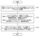
- Step S101 When the internal switch 10-1 detects a communication timeout (time out) with the controller 20, a link down of a port (VLAN port, physical port, etc.) used for connection to the external switch 30 is established. To implement. Further, the internal switch 10-1 can also be configured to link down the ports used for the connection between the internal switches in the same manner as the ports used for the connection with the external switch 30.
- a communication timeout time out
- the internal switch 10-1 can also be configured to link down the ports used for the connection between the internal switches in the same manner as the ports used for the connection with the external switch 30.
- Link down refers to a state in which communication is not possible in the data link layer, which is the second layer of communication. In other words, link down means that a link is disconnected and communication cannot be performed by closing an electronic / physical port by hardware control / software control or stopping signal output from the port. Point to.
- Step S102 When the controller 20 detects a communication timeout with the internal switch 10-1, the controller 20 calculates the optimum route that does not pass through the internal switch 10-1, updates the flow table for switching the route, and -1 is disconnected from the OpenFlow network, and an optimal route that does not pass through the internal switch 10-1 is set for the internal switches 10-2 to 10-4.
- the information regarding the output port and the forwarding destination of each traffic is changed.
- Step S103 The external switch 30 detects the link down of the port used for connection with the internal switch 10-1, and switches the route so that the traffic transferred to the internal switch 10-1 is transferred to the internal switch 10-2. .
- the external switch 30 may switch the route so that the traffic transferred to the internal switch 10-1 is transferred to a switch on another network.
- a switch on another network an internal switch (an internal switch routed by a controller other than the controller 20) arranged in another OpenFlow network, another external switch, or the like can be considered.
- the internal switch 10-1 registers in advance the port to be linked down in the emergency table (Emergency table).
- the internal switch 10-1 registers in advance the port to be used for connection with the external switch 30 as the port for performing the link down in the emergency table.
- the internal switch 10-1 may register the port in the emergency table under the control of the controller 20.
- the internal switch 10-1 When the internal switch 10-1 detects a communication timeout (time out) with the controller 20, the internal switch 10-1 determines that the controller 20 itself or a communication line with the controller 20 has failed, refers to the emergency table, Check for pre-registered ports
- the internal switch 10-1 performs link-down of the port when there is a pre-registered port. On the other hand, the internal switch 10-1 does not perform link down of the port when there is no pre-registered port.
- the internal switch 10-1 may check whether a pre-registered port is a port used for connection to the external switch 30 when a pre-registered port exists. Is possible. For example, the internal switch 10-1 confirms a port registered in advance and confirms whether it is being used for connection with the external switch 30.
- the internal switch 10-1 when the pre-registered port is a port used for connection to the external switch 30, the internal switch 10-1 performs link-down of the port. On the other hand, the internal switch 10-1 does not perform link-down of the port if it is not a port used for connection to the external switch 30 even if a pre-registered port exists.
- the internal switch 10-1 refers to the flow table and deletes (clears) the route information (flow entry or the like) indicating the traffic transfer route for the external switch 30 and from the external switch 30. For example, the internal switch 10-1 initializes the flow table.
- the deletion of the route information is performed after the processing relating to the link down of the port is completed in order to avoid the loss of the route while being connected to the external switch 30. .
- the internal switch 10-1 can also link down the ports used for connection to the internal switches 10-2 to 10-4 as necessary.
- the internal switch 10-1 registers the ports used for connection with the internal switch 10-2 to the internal switch 10-4 in advance in the emergency table as the ports for performing the link down. It is possible to link down the ports used for connection with the switch 10-2 to the internal switch 10-4.
- the internal switch 10-2 to the internal switch 10-4 each detect a link down of the port used for connection to the internal switch 10-1, the connection state between itself and the controller 20 is detected. If the connection state between the own device and the controller 20 is normal, the controller 20 may be requested to perform route control to set a new optimum route.
- Each of the internal switch 10-2 to the internal switch 10-4 detects a communication timeout with the controller 20 if the connection state between itself and the controller 20 is not normal. 1 is performed.
- the controller 20 When detecting a communication timeout with the internal switch 10-1, the controller 20 determines that a failure has occurred in the internal switch 10-1 itself or a communication line with the internal switch 10-1, and does not pass through the internal switch 10-1. Calculate the optimal route.
- the controller 20 updates the flow table for switching the path, disconnects the internal switch 10-1 from the network, and sets the optimal path for the internal switches 10-2 to 10-4. At this time, the internal switches 10-2 to 10-4 register a flow entry indicating that the traffic is transferred to the optimum route in the flow table according to the setting of the optimum route from the controller 20, and transfer the traffic to the optimum route. Start.
- the external switch 30 When the external switch 30 detects a link down of the port used for connection with the internal switch 10-1, the external switch 30 transfers the traffic transferred to the internal switch 10-1 to another switch (internal switch 10-2 or other Switch the route so that it is forwarded to a switch on the network, and start traffic forwarding.
- another switch internal switch 10-2 or other Switch the route so that it is forwarded to a switch on the network, and start traffic forwarding.
- the external switch 30 switches the traffic output port from a port used for connection with the internal switch 10-1 to a port used for connection with another switch, and starts traffic transfer.
- the external switch 30 may try to connect to the internal switch 10-1 again when the external switch 30 detects a link down of a port used for connection to the internal switch 10-1. .
- the link down is caused by the processing of the internal switch 10-1 as in step S101, the internal switch 10-1 has not received control from the controller 20 and the flow table is initialized, but operates normally. Therefore, if there is initial (default) route information, traffic forwarding is possible based on the route information.
- the external switch 30 transfers to the internal switch 10-1.
- the route is switched so that the traffic is transferred to another switch, and the traffic transfer is started.
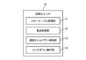
- the flow table management unit 11 receives a control message conforming to the open flow protocol from the controller 20 via a secure channel, and registers a flow entry in the flow table of the own device based on the content of the control message.
- the transfer processing unit 12 processes the received packet according to the flow entry registered in its own flow table.
- the communication timeout detection unit 13 monitors a secure channel connected to the controller 20 and detects a communication timeout with the controller 20.
- the link-down execution unit 14 links the port used for connection with the external switch 30 when a communication timeout with the controller 20 is detected. Carry down.
- the controller 20 includes an optimum route calculation unit 21, a route control unit 22, and a communication timeout detection unit 23.
- the internal switch is disconnected from the OpenFlow network, and the other internal switch is set so as to switch from the current route via the internal switch to the optimum route via the other internal switch.
- the external switch 30 includes a transfer processing unit 31, a link down detection unit 32, and a path switching unit 33.
- the internal switch and the controller cannot communicate with each other, the internal switch that cannot be controlled from the controller is disconnected from the network, so that it is possible to prevent the control plane and the data plane from mismatching.
- the problem can be analyzed by logging in to the internal switch via the other internal switch.
- the radio 60-1 is connected to the internal switch 10-3.
- the radio device 60-2 is connected to the internal switch 10-4 as a redundant path of the radio device 60-1.
- the terminal 40 makes a connection request to the wireless device 60-1 and connects by the wireless access method.
- the wireless device 60-1 When the wireless device 60-1 becomes unable to communicate with the controller 20, the wireless device 60-1 stops the wave (stops the transmission of radio waves) in the wireless access with the terminal 40.
- This “execution of wave stop” corresponds to “execution of link down” in another embodiment.
- the terminal 40 Since the terminal 40 is disconnected from the wireless device 60-1 by the wireless access method, the terminal 40 is connected to the wireless device 60-2 by the wireless access method.
- SCADA Supervision Control Acquire Data key
- base station base station
- AP Access Point
- CS Commune
- the controller 20, the terminal 40, and the server 50 a computer such as a PC (personal computer), an appliance, a thin client terminal / server, a workstation, a mainframe, and a supercomputer is assumed.
- the terminal 40 include an IP phone, a mobile phone, a smart phone, a smart book, a car navigation system (car navigation system), a portable game machine, a home game machine, a portable music player, a handy terminal, a gadget (electronic device), An interactive TV, a digital tuner, a digital recorder, an information home appliance (information home appliance), an office automation (OA) device, an over-the-counter terminal / high-function copier, a digital signage (digital signage), and the like are also conceivable.
- the controller 20, the terminal 40, and the server 50 may be relay devices or peripheral devices.
- an expansion board mounted on a physical machine or a virtual machine (VM) constructed on a physical machine may be used.
- VM virtual machine
- processors include a CPU (Central Processing Unit), a network processor (NP: Network Processor), a microprocessor (microprocessor), a microcontroller (microcontroller), or a semiconductor integrated circuit (LSI: Large Scale) having a dedicated function. Integration) or the like.
- CPU Central Processing Unit
- NP Network Processor
- microprocessor microprocessor
- microcontroller microcontroller
- LSI semiconductor integrated circuit
- semiconductor storage devices such as RAM (Random Access Memory), ROM (Read Only Memory), EEPROM (Electrically Erasable and Programmable Read Only Memory), and HDD Memory (SDHidK)
- RAM Random Access Memory
- ROM Read Only Memory
- EEPROM Electrically Erasable and Programmable Read Only Memory
- HDD Memory HDD Memory
- An auxiliary storage device such as State Drive
- a removable disk such as a DVD (Digital Versatile Disk)
- a storage medium such as an SD memory card (Secure Digital memory card), or the like
- a buffer, a register, or the like may be used.
- DAS Direct Attached Storage
- FC-SAN Fibre Channel-Storage Area Network
- NAS Network Attached Storage
- IP-SAN IP-Storage Area
- processor and the memory may be integrated.
- a single chip such as a microcomputer has been developed. Therefore, a case where a one-chip microcomputer mounted on an electronic device or the like includes the processor and the memory can be considered.
- Examples of the above interfaces include semiconductor integrated circuits such as substrates (motherboards, I / O boards) and chips that support network communication, network adapters such as NIC (Network Interface Card), and similar expansion cards, communication devices such as antennas, etc.
- a communication port such as a connection port (connector) is conceivable.
- networks include the Internet, LAN (Local Area Network), wireless LAN (Wireless LAN), WAN (Wide Area Network), backbone (Backbone), cable TV (CATV) line, fixed telephone network, mobile phone network, WiMAX (IEEE 802.16a), 3G (3rd Generation), dedicated line (lease line), IrDA (Infrared Data Association), Bluetooth (registered trademark), serial communication line, data bus, and the like are conceivable.
- the component may be a module, a component, a dedicated device, or an activation (calling) program thereof.
- the present invention is directed to a CD separation type network such as an OpenFlow network.
- the OpenFlow network is only an example.
- the present invention can also be directed to a network that performs route control other than “updating a flow table using open flow technology”.
- the present invention is characterized in that it is possible to solve the problem that the route detour cannot be switched properly when a communication failure occurs at the boundary between the CD-separated network and the normal network.
- the path is detoured by the port shutdown at the boundary of the CD separation type network.
- the controller updates the flow table for each of the plurality of internal switches, and makes the route formed by the plurality of internal switches the optimum route.
- the internal switch A forms an optimum route with the external switch and becomes an active internal switch.
- the internal switch B forms a redundant path with the external switch and becomes a standby internal switch.
- the controller When a failure occurs in the internal switch A, the controller is switched from a route via the internal switch A to a route via the internal switch B by updating the flow table for each of the plurality of internal switches.
- the internal switch A When the internal switch A detects that the connection between the controller and the internal switch A is no longer possible, the internal switch A performs link down of the port connected to the external switch.
- the external switch When the external switch detects the link down of the port connected to the internal switch A, the external switch switches the path and transfers the traffic to the internal switch A of the active system to the internal switch B of the standby system.
- Switches located in the network Multiple switches located in the network; A controller that sets a flow entry in which rules and actions for uniformly controlling a packet as a flow are defined in a flow table of each of the plurality of switches; An external communication device that exists outside the network and is connected to an active switch among the plurality of switches, When the working switch detects a communication timeout with the controller, it performs link down of the port used for connection with the external communication device, When the controller detects a communication timeout with the active switch, the controller disconnects the active switch from the network, and performs path control to switch to a path via the standby switch among the plurality of switches.
- the external communication device When the external communication device detects a link down of a port used for connection with the active switch, the external communication device transmits the traffic transmitted to the active switch to the outside of the standby switch and the network.
- a communication path control system that sends to one of the existing switches.
- Appendix 4 A communication path control system according to any one of appendices 1 to 3, When the active switch is connected to the external communication device by a wireless access method, the active switch performs a wave stop when a communication timeout with the controller is detected, and a port used for connection with the external communication device Communication path control system that performs link down.
Landscapes
- Engineering & Computer Science (AREA)
- Computer Networks & Wireless Communication (AREA)
- Signal Processing (AREA)
- Data Exchanges In Wide-Area Networks (AREA)
- Mobile Radio Communication Systems (AREA)
Abstract
Description
機能を分離した集中管理型のネットワークの1つとして、コントロールプレーン側の制御装置からデータプレーン側のノード装置を制御するCD(C:コントロールプレーン/D:データプレーン)分離型ネットワークが提案されている。 [Description of CD-separated network]
A CD (C: control plane / D: data plane) separation type network that controls a data plane side node device from a control device on the control plane side is proposed as one of the centralized management type networks with separated functions. .
オープンフローネットワークでは、制御装置に相当するオープンフローコントローラ(OFC:OpenFlow Controller)が、ノード装置に相当するオープンフロースイッチ(OFS:OpenFlow Switch)の経路制御に関するフローテーブル(Flow table)を操作することにより、オープンフロースイッチ(OFS)の挙動を制御する。 [Explanation of OpenFlow network]
In the OpenFlow network, an OpenFlow controller (OFC) corresponding to a control device operates a flow table (Flow table) related to path control of an OpenFlow switch (OFS) corresponding to a node device. Control the behavior of the OpenFlow switch (OFS).
図1を参照して、従来のオープンフローネットワークについて説明する。ここでは、内部スイッチが4台である場合を例に説明する。 [Example of a conventional OpenFlow network]
A conventional OpenFlow network will be described with reference to FIG. Here, a case where there are four internal switches will be described as an example.
従来のオープンフローネットワークにおいては、次のような課題がある。 [Problems of conventional OpenFlow network]
The conventional OpenFlow network has the following problems.
以下に、本発明の第1実施形態について添付図面を参照して説明する。 <First Embodiment>
Hereinafter, a first embodiment of the present invention will be described with reference to the accompanying drawings.
図2に示すように、本発明の第1実施形態に係る通信経路制御システムは、内部スイッチ10(10-i、i=1~n:nは任意)と、コントローラ20と、外部スイッチ30と、端末40と、サーバ50を含む。 [System configuration]
As shown in FIG. 2, the communication path control system according to the first embodiment of the present invention includes an internal switch 10 (10-i, i = 1 to n: n is arbitrary), a
次に、図3を参照して、内部スイッチ10-1の障害発生時の動作について説明する。 [Action when a failure occurs]
Next, with reference to FIG. 3, the operation of the internal switch 10-1 when a failure occurs will be described.
内部スイッチ10-1は、コントローラ20との通信タイムアウト(time out:時間切れ)を検知した際に、外部スイッチ30との接続に使用するポート(VLANポート、物理ポート等)のリンクダウン(linkdown)を実施する。また、内部スイッチ10-1は、外部スイッチ30との接続に使用するポートと同様に、内部スイッチ間の接続に使用するポートのリンクダウンを実施するようにすることも可能である。 (1) Step S101
When the internal switch 10-1 detects a communication timeout (time out) with the
コントローラ20は、内部スイッチ10-1との通信タイムアウトを検知した際に、内部スイッチ10-1を経由しない最適経路を計算し、経路の切り替えを行うためのフローテーブルの更新を行い、内部スイッチ10-1をオープンフローネットワークから切り離し、内部スイッチ10-2~10-4に対して、内部スイッチ10-1を経由しない最適経路を設定する。 (2) Step S102
When the
外部スイッチ30は、内部スイッチ10-1との接続に使用するポートのリンクダウンを検知し、内部スイッチ10-1に転送していたトラヒックを内部スイッチ10-2に転送するように、経路を切り替える。なお、実際には、外部スイッチ30は、内部スイッチ10-1に転送していたトラヒックを、他のネットワーク上のスイッチに転送するように、経路を切り替えても良い。他のネットワーク上のスイッチの例として、他のオープンフローネットワークに配置された内部スイッチ(コントローラ20以外のコントローラにより経路制御される内部スイッチ)や、他の外部スイッチ等が考えられる。 (3) Step S103
The
内部スイッチの動作(図3のステップS101)の詳細について説明する。 [Details of internal switch operation]
Details of the operation of the internal switch (step S101 in FIG. 3) will be described.
コントローラの動作(図3のステップS102)の詳細について説明する。 [Details of controller operation]
Details of the operation of the controller (step S102 in FIG. 3) will be described.
外部スイッチの動作(図3のステップS101)の詳細について説明する。 [Details of external switch operation]
Details of the operation of the external switch (step S101 in FIG. 3) will be described.
次に、図4を参照して、内部スイッチの構成例について説明する。 [Configuration of internal switch]
Next, a configuration example of the internal switch will be described with reference to FIG.
次に、図5を参照して、コントローラの構成例について説明する。 [Controller configuration]
Next, a configuration example of the controller will be described with reference to FIG.
次に、図6を参照して、外部スイッチの構成例について説明する。 [Configuration of external switch]
Next, a configuration example of the external switch will be described with reference to FIG.
本実施形態では、内部スイッチから外部スイッチへのリンクをダウンしているので、内部スイッチをネットワークから切り離すことができる。 [Effect of this embodiment]
In the present embodiment, since the link from the internal switch to the external switch is down, the internal switch can be disconnected from the network.
以下に、本発明の第2実施形態について説明する。 Second Embodiment
The second embodiment of the present invention will be described below.
図7に示すように、本発明の第2実施形態に係る通信経路制御システムは、内部スイッチ10(10-i、i=1~n)と、コントローラ20と、端末40と、サーバ50と、無線機60(60-j、j=1~m:mは任意)を含む。 [System configuration]
As shown in FIG. 7, the communication path control system according to the second embodiment of the present invention includes an internal switch 10 (10-i, i = 1 to n), a
端末40は、無線機60-1に対して接続要求を行い、無線アクセス方式で接続する。 [Details of this embodiment]
The terminal 40 makes a connection request to the wireless device 60-1 and connects by the wireless access method.
本実施形態では、無線アクセスをネットワークの経路制御と連動させているので、経路制御と連動した無線アクセスにより、電波資源も含めたリソースを有効活用することができる。 [Effect of this embodiment]
In the present embodiment, since wireless access is linked to network path control, resources including radio wave resources can be effectively used by wireless access linked to path control.
なお、上記の各実施形態は、組み合わせて実施することも可能である。 <Relationship between each embodiment>
Note that the above embodiments can be implemented in combination.
以下に、本発明に係るネットワークシステムを実現するための具体的なハードウェアの例について説明する。 <Example of hardware>
Hereinafter, specific examples of hardware for realizing the network system according to the present invention will be described.
以上のように、本発明は、オープンフローネットワークを始めとするCD分離型ネットワークを対象としている。なお、オープンフローネットワークは一例に過ぎない。実際には、本発明は、「オープンフロー技術を使用したフローテーブルの更新」以外の経路制御を行うネットワークを対象とすることもできる。 <Features of the present invention>
As described above, the present invention is directed to a CD separation type network such as an OpenFlow network. The OpenFlow network is only an example. In practice, the present invention can also be directed to a network that performs route control other than “updating a flow table using open flow technology”.
上記の実施形態の一部又は全部は、以下の付記のように記載することも可能である。但し、実際には、以下の記載例に限定されない。 <Appendix>
Part or all of the above-described embodiments can be described as in the following supplementary notes. However, actually, it is not limited to the following description examples.
ネットワークに配置された複数のスイッチと、
パケットをフローとして一律に制御するためのルールとアクションが定義されたフローエントリを、前記複数のスイッチの各々のフローテーブルに設定するコントローラと、
前記ネットワークの外側に存在し、前記複数のスイッチのうち現用系のスイッチと接続する外部通信装置と
を含み、
前記現用系のスイッチは、前記コントローラとの通信タイムアウトを検知した場合、前記外部通信装置との接続に使用するポートのリンクダウンを実施し、
前記コントローラは、前記現用系のスイッチとの通信タイムアウトを検知した場合、前記現用系のスイッチを前記ネットワークから切り離し、前記複数のスイッチのうち待機系のスイッチを経由する経路へ切り替える経路制御を実施し、
前記外部通信装置は、前記現用系のスイッチとの接続に使用するポートのリンクダウンを検知した場合、前記現用系のスイッチに送信していたトラヒックを、前記待機系のスイッチ及び前記ネットワークの外側に存在するスイッチのいずれかに送信する
通信経路制御システム。 (Appendix 1)
Multiple switches located in the network;
A controller that sets a flow entry in which rules and actions for uniformly controlling a packet as a flow are defined in a flow table of each of the plurality of switches;
An external communication device that exists outside the network and is connected to an active switch among the plurality of switches,
When the working switch detects a communication timeout with the controller, it performs link down of the port used for connection with the external communication device,
When the controller detects a communication timeout with the active switch, the controller disconnects the active switch from the network, and performs path control to switch to a path via the standby switch among the plurality of switches. ,
When the external communication device detects a link down of a port used for connection with the active switch, the external communication device transmits the traffic transmitted to the active switch to the outside of the standby switch and the network. A communication path control system that sends to one of the existing switches.
付記1に記載の通信経路制御システムであって、
リンクダウンを実施するポートを予め決めておき、前記コントローラとの通信タイムアウトを検知した場合、予め決められたポートの有無を確認し、予め決められたポートが存在する場合、当該ポートのリンクダウンを実施する
通信経路制御システム。 (Appendix 2)
The communication path control system according to
When a port to perform link down is determined in advance and a communication timeout with the controller is detected, the presence or absence of a predetermined port is confirmed. If a predetermined port exists, link down of the port is performed. Implement the communication path control system.
付記1又は2に記載の通信経路制御システムであって、
前記現用系のスイッチは、前記複数のスイッチの各々と相互に接続しており、前記コントローラとの通信タイムアウトを検知した場合、前記複数のスイッチの各々との接続に使用するポートのリンクダウンを実施し、
前記複数のスイッチの各々は、前記現用系のスイッチとの接続に使用するポートのリンクダウンを検知した場合、前記コントローラとの接続状態を確認し、前記コントローラとの接続状態が正常であれば、前記コントローラに対して経路制御を要求して新たな最適経路を設定し、前記コントローラとの接続状態が正常でなければ、前記コントローラとの通信タイムアウトを検知する
通信経路制御システム。 (Appendix 3)
The communication path control system according to
The active switch is interconnected with each of the plurality of switches, and when a communication timeout with the controller is detected, a link down of a port used for connection with each of the plurality of switches is performed. And
Each of the plurality of switches, when detecting a link down of a port used for connection with the active switch, confirms the connection state with the controller, and if the connection state with the controller is normal, A communication path control system that requests path control from the controller, sets a new optimum path, and detects a communication timeout with the controller if the connection state with the controller is not normal.
付記1乃至3のいずれかに記載の通信経路制御システムであって、
前記現用系のスイッチは、前記外部通信装置と無線アクセス方式で接続する場合、前記コントローラとの通信タイムアウトを検知した際に停波を実施して、前記外部通信装置との接続に使用するポートのリンクダウンを実施する
通信経路制御システム。 (Appendix 4)
A communication path control system according to any one of
When the active switch is connected to the external communication device by a wireless access method, the active switch performs a wave stop when a communication timeout with the controller is detected, and a port used for connection with the external communication device Communication path control system that performs link down.
以上、本発明の実施形態を詳述してきたが、実際には、上記の実施形態に限られるものではなく、本発明の要旨を逸脱しない範囲の変更があっても本発明に含まれる。 <Remarks>
As mentioned above, although embodiment of this invention was explained in full detail, actually, it is not restricted to said embodiment, Even if there is a change of the range which does not deviate from the summary of this invention, it is included in this invention.
Claims (10)
- ネットワークに配置された複数のスイッチと、
前記複数のスイッチの各々に対する経路制御を行うコントローラと、
前記ネットワークの外側に存在し、前記複数のスイッチのうち現用系のスイッチと接続する外部通信装置と
を含み、
前記現用系のスイッチは、前記コントローラとの通信タイムアウトを検知した場合、前記外部通信装置との接続に使用するポートのリンクダウンを実施し、
前記コントローラは、前記現用系のスイッチとの通信タイムアウトを検知した場合、前記現用系のスイッチを前記ネットワークから切り離し、前記複数のスイッチのうち待機系のスイッチを経由する経路へ切り替える経路制御を実施し、
前記外部通信装置は、前記現用系のスイッチとの接続に使用するポートのリンクダウンを検知した場合、前記現用系のスイッチに送信していたトラヒックを、前記待機系のスイッチ及び前記ネットワークの外側に存在するスイッチのいずれかに送信する
通信経路制御システム。 Multiple switches located in the network;
A controller that performs path control for each of the plurality of switches;
An external communication device that exists outside the network and is connected to an active switch among the plurality of switches,
When the working switch detects a communication timeout with the controller, it performs link down of the port used for connection with the external communication device,
When the controller detects a communication timeout with the active switch, the controller disconnects the active switch from the network, and performs path control to switch to a path via the standby switch among the plurality of switches. ,
When the external communication device detects a link down of a port used for connection with the active switch, the external communication device transmits the traffic transmitted to the active switch to the outside of the standby switch and the network. A communication path control system that sends to one of the existing switches. - 請求項1に記載の通信経路制御システムであって、
前記現用系のスイッチは、リンクダウンを実施するポートを予め決めておき、前記コントローラとの通信タイムアウトを検知した場合、予め決められたポートの有無を確認し、予め決められたポートが存在する場合、当該ポートのリンクダウンを実施する
通信経路制御システム。 The communication path control system according to claim 1,
The active switch determines a port for performing link-down in advance, detects a communication timeout with the controller, checks the presence / absence of a predetermined port, and has a predetermined port A communication path control system that performs link down of the port. - 請求項1に記載の通信経路制御システムであって、
前記現用系のスイッチは、前記複数のスイッチの各々と相互に接続しており、前記コントローラとの通信タイムアウトを検知した場合、前記複数のスイッチの各々との接続に使用するポートのリンクダウンを実施し、
前記複数のスイッチの各々は、前記現用系のスイッチとの接続に使用するポートのリンクダウンを検知した場合、前記コントローラとの接続状態を確認し、前記コントローラとの接続状態が正常であれば、前記コントローラに対して経路制御を要求して新たな最適経路を設定し、前記コントローラとの接続状態が正常でなければ、前記コントローラとの通信タイムアウトを検知する
通信経路制御システム。 The communication path control system according to claim 1,
The active switch is interconnected with each of the plurality of switches, and when a communication timeout with the controller is detected, a link down of a port used for connection with each of the plurality of switches is performed. And
Each of the plurality of switches, when detecting a link down of a port used for connection with the active switch, confirms the connection state with the controller, and if the connection state with the controller is normal, A communication path control system that requests path control from the controller, sets a new optimum path, and detects a communication timeout with the controller if the connection state with the controller is not normal. - 請求項1に記載の通信経路制御システムであって、
前記現用系のスイッチは、前記外部通信装置と無線アクセス方式で接続する場合、前記コントローラとの通信タイムアウトを検知した際に停波を実施して、前記外部通信装置との接続に使用するポートのリンクダウンを実施する
通信経路制御システム。 The communication path control system according to claim 1,
When the active switch is connected to the external communication device by a wireless access method, the active switch performs a wave stop when a communication timeout with the controller is detected, and a port used for connection with the external communication device Communication path control system that performs link down. - 請求項1乃至4のいずれか一項に記載の通信経路制御システムで、スイッチ、コントローラ、及び外部通信装置のいずれかとして使用される計算機。 A computer used as one of a switch, a controller, and an external communication device in the communication path control system according to any one of claims 1 to 4.
- コントローラが、ネットワークに配置された複数のスイッチの各々に対する経路制御を行うことと、
前記ネットワークの外側に存在する外部通信装置が、前記複数のスイッチのうち現用系のスイッチと接続することと、
前記現用系のスイッチが、前記コントローラとの通信タイムアウトを検知した場合、前記外部通信装置との接続に使用するポートのリンクダウンを実施することと、
前記コントローラが、前記現用系のスイッチとの通信タイムアウトを検知した場合、前記現用系のスイッチを前記ネットワークから切り離し、前記複数のスイッチのうち待機系のスイッチを経由する経路へ切り替える経路制御を実施することと、
前記外部通信装置が、前記現用系のスイッチとの接続に使用するポートのリンクダウンを検知した場合、前記現用系のスイッチに送信していたトラヒックを、前記待機系のスイッチ及び前記ネットワークの外側に存在するスイッチのいずれかに送信することと
を含む
通信経路制御方法。 The controller performs path control for each of the plurality of switches arranged in the network;
An external communication device existing outside the network is connected to an active switch among the plurality of switches;
When the active switch detects a communication timeout with the controller, performing link down of a port used for connection with the external communication device;
When the controller detects a communication timeout with the active switch, the controller disconnects the active switch from the network, and performs path control to switch to a path via the standby switch among the plurality of switches. And
When the external communication device detects a link down of a port used for connection with the active switch, the traffic transmitted to the active switch is transferred to the outside of the standby switch and the network. A communication path control method including transmitting to any of existing switches. - 請求項6に記載の通信経路制御方法であって、
前記現用系のスイッチが、
リンクダウンを実施するポートを予め決めておき、前記コントローラとの通信タイムアウトを検知した場合、予め決められたポートの有無を確認することと、
予め決められたポートが存在する場合、当該ポートのリンクダウンを実施すること
を更に含む
通信経路制御方法。 The communication path control method according to claim 6,
The active switch is
Predetermining the port to be linked down, and detecting the communication timeout with the controller, checking the presence or absence of a predetermined port;
A communication path control method further comprising performing link down of the port when a predetermined port exists. - 請求項6に記載の通信経路制御方法であって、
前記現用系のスイッチが、
前記複数のスイッチの各々と相互に接続することと、
前記コントローラとの通信タイムアウトを検知した場合、前記複数のスイッチの各々との接続に使用するポートのリンクダウンを実施することと、
前記複数のスイッチの各々が、
前記現用系のスイッチとの接続に使用するポートのリンクダウンを検知した場合、前記コントローラとの接続状態を確認することと、
前記コントローラとの接続状態が正常であれば、前記コントローラに対して経路制御を要求して新たな最適経路を設定することと、
前記コントローラとの接続状態が正常でなければ、前記コントローラとの通信タイムアウトを検知することと
を更に含む
通信経路制御方法。 The communication path control method according to claim 6,
The active switch is
Interconnecting with each of the plurality of switches;
When a communication timeout with the controller is detected, performing a link down of a port used for connection with each of the plurality of switches;
Each of the plurality of switches is
When detecting a link down of the port used for connection with the active switch, checking the connection state with the controller;
If the connection state with the controller is normal, requesting path control to the controller and setting a new optimum path;
A communication path control method further comprising: detecting a communication timeout with the controller if a connection state with the controller is not normal. - 請求項6に記載の通信経路制御方法であって、
前記現用系のスイッチが、前記外部通信装置と無線アクセス方式で接続する場合、前記コントローラとの通信タイムアウトを検知した際に停波を実施して、前記外部通信装置との接続に使用するポートのリンクダウンを実施すること
を更に含む
通信経路制御方法。 The communication path control method according to claim 6,
When the active switch is connected to the external communication device by a wireless access method, a wave is stopped when a communication timeout with the controller is detected, and the port used for connection to the external communication device A communication path control method further comprising performing link down. - 請求項6乃至9のいずれか一項に記載の通信経路制御方法における処理を、スイッチ、コントローラ、及び外部通信装置のいずれかとして使用される計算機に実行させるためのプログラム。 A program for causing a computer used as one of a switch, a controller, and an external communication device to execute the processing in the communication path control method according to any one of claims 6 to 9.
Priority Applications (6)
| Application Number | Priority Date | Filing Date | Title |
|---|---|---|---|
| KR1020137031775A KR101562726B1 (en) | 2011-05-30 | 2012-05-29 | Communication path control system, and communication path control method |
| US14/122,003 US10554585B2 (en) | 2011-05-30 | 2012-05-29 | Communication route control system and communication route control method |
| CN201280026777.4A CN103621027B (en) | 2011-05-30 | 2012-05-29 | Communication route control system and communication route control method |
| EP12792780.4A EP2717520B1 (en) | 2011-05-30 | 2012-05-29 | Communication path control system, and communication path control method |
| RU2013157203/08A RU2562760C2 (en) | 2011-05-30 | 2012-05-29 | Control system of communication route, and route control method |
| JP2013518111A JP5660211B2 (en) | 2011-05-30 | 2012-05-29 | Communication path control system and communication path control method |
Applications Claiming Priority (2)
| Application Number | Priority Date | Filing Date | Title |
|---|---|---|---|
| JP2011120115 | 2011-05-30 | ||
| JP2011-120115 | 2011-05-30 |
Publications (1)
| Publication Number | Publication Date |
|---|---|
| WO2012165446A1 true WO2012165446A1 (en) | 2012-12-06 |
Family
ID=47259300
Family Applications (1)
| Application Number | Title | Priority Date | Filing Date |
|---|---|---|---|
| PCT/JP2012/063817 WO2012165446A1 (en) | 2011-05-30 | 2012-05-29 | Communication path control system, and communication path control method |
Country Status (7)
| Country | Link |
|---|---|
| US (1) | US10554585B2 (en) |
| EP (1) | EP2717520B1 (en) |
| JP (1) | JP5660211B2 (en) |
| KR (1) | KR101562726B1 (en) |
| CN (1) | CN103621027B (en) |
| RU (1) | RU2562760C2 (en) |
| WO (1) | WO2012165446A1 (en) |
Cited By (7)
| Publication number | Priority date | Publication date | Assignee | Title |
|---|---|---|---|---|
| CN103391296A (en) * | 2013-07-29 | 2013-11-13 | 北京华为数字技术有限公司 | Controller, openflow switch and method and system of channel establishing |
| JP5503762B1 (en) * | 2013-02-19 | 2014-05-28 | 三菱電機インフォメーションシステムズ株式会社 | Open flow network system |
| CN103888313A (en) * | 2014-03-11 | 2014-06-25 | 浙江大学 | Method for forecasting optimal timeout of flow table item |
| WO2014132967A1 (en) * | 2013-02-26 | 2014-09-04 | 日本電気株式会社 | Communication system, switch, control apparatus, control channel configuration method and program |
| CN104243196A (en) * | 2013-06-21 | 2014-12-24 | 中兴通讯股份有限公司 | Virtual network mapping protection method and system under SDN architecture |
| WO2015027246A1 (en) | 2013-08-23 | 2015-02-26 | Samsung Electronics Co., Ltd. | Mobile software defined networking (mobisdn) |
| JP2015082742A (en) * | 2013-10-22 | 2015-04-27 | 富士通株式会社 | Transfer device, control device and transfer method |
Families Citing this family (11)
| Publication number | Priority date | Publication date | Assignee | Title |
|---|---|---|---|---|
| US9374308B2 (en) * | 2013-08-30 | 2016-06-21 | Lenovo Enterprise Solutions (Singapore) Pte. Ltd. | Openflow switch mode transition processing |
| CN104954271B (en) * | 2014-03-26 | 2018-11-30 | 国际商业机器公司 | Data package processing method and device in SDN network |
| US9491031B2 (en) * | 2014-05-06 | 2016-11-08 | At&T Intellectual Property I, L.P. | Devices, methods, and computer readable storage devices for collecting information and sharing information associated with session flows between communication devices and servers |
| WO2015184586A1 (en) | 2014-06-03 | 2015-12-10 | 华为技术有限公司 | Openflow communication method, system, controller, and service gateway |
| US9935900B2 (en) | 2014-10-16 | 2018-04-03 | Electronics And Telecommunications Research Institute | Method for providing protection switching service in virtual tenant network and controller therefor |
| CN104301146A (en) * | 2014-10-23 | 2015-01-21 | 杭州华三通信技术有限公司 | Link switching method and device in software defined network |
| US10374946B2 (en) * | 2015-03-16 | 2019-08-06 | Dell Products L.P. | Centralized wireless network management system |
| CN105338331B (en) * | 2015-12-16 | 2018-08-24 | 武汉微创光电股份有限公司 | A kind of non-compression video monitoring system and fault recovery method |
| CN106302265B (en) * | 2016-07-21 | 2019-08-06 | 新华三技术有限公司 | Message forwarding method and device |
| CN107070791A (en) * | 2016-12-29 | 2017-08-18 | 北京邮电大学 | A kind of SDN system and its data transmission method |
| CN113630314B (en) * | 2020-05-09 | 2022-09-16 | 北京金山云网络技术有限公司 | Disaster recovery method and device for hybrid cloud private line access network |
Citations (2)
| Publication number | Priority date | Publication date | Assignee | Title |
|---|---|---|---|---|
| JP2006352544A (en) * | 2005-06-16 | 2006-12-28 | Kddi Corp | Redundant system of layer 2 network |
| JP2011120115A (en) | 2009-12-04 | 2011-06-16 | Canon Inc | Image processing apparatus and control method thereof |
Family Cites Families (11)
| Publication number | Priority date | Publication date | Assignee | Title |
|---|---|---|---|---|
| US6333932B1 (en) * | 1994-08-22 | 2001-12-25 | Fujitsu Limited | Connectionless communications system, its test method, and intra-station control system |
| US6934248B1 (en) * | 2000-07-20 | 2005-08-23 | Nortel Networks Limited | Apparatus and method for optical communication protection |
| JP3580250B2 (en) * | 2000-12-22 | 2004-10-20 | 株式会社デンソー | Wireless communication system, network and mobile terminal used in wireless communication system |
| US7313089B2 (en) * | 2001-12-21 | 2007-12-25 | Agere Systems Inc. | Method and apparatus for switching between active and standby switch fabrics with no loss of data |
| US7656790B2 (en) * | 2004-06-28 | 2010-02-02 | Hewlett-Packard Development Company, L.P. | Handling link failures with re-tagging |
| JP2008227558A (en) | 2005-06-24 | 2008-09-25 | Yaskawa Electric Corp | Network adapter, communication terminal, communication path distribution method and program thereof |
| RU2332803C2 (en) * | 2005-11-17 | 2008-08-27 | Общество с ограниченной ответственностью "ХитТелеком" | Communication system |
| US8457121B1 (en) * | 2006-08-01 | 2013-06-04 | Hewlett-Packard Development Company, L.P. | Heterogeneous network switch system |
| US8159935B1 (en) * | 2009-01-12 | 2012-04-17 | Shoretel, Inc. | Failover system and method for IP telephony |
| WO2011144495A1 (en) * | 2010-05-19 | 2011-11-24 | Telefonaktiebolaget L M Ericsson (Publ) | Methods and apparatus for use in an openflow network |
| US9001827B2 (en) * | 2010-12-17 | 2015-04-07 | Big Switch Networks, Inc. | Methods for configuring network switches |
-
2012
- 2012-05-29 KR KR1020137031775A patent/KR101562726B1/en not_active IP Right Cessation
- 2012-05-29 RU RU2013157203/08A patent/RU2562760C2/en not_active IP Right Cessation
- 2012-05-29 CN CN201280026777.4A patent/CN103621027B/en not_active Expired - Fee Related
- 2012-05-29 EP EP12792780.4A patent/EP2717520B1/en not_active Not-in-force
- 2012-05-29 US US14/122,003 patent/US10554585B2/en active Active
- 2012-05-29 JP JP2013518111A patent/JP5660211B2/en active Active
- 2012-05-29 WO PCT/JP2012/063817 patent/WO2012165446A1/en active Application Filing
Patent Citations (2)
| Publication number | Priority date | Publication date | Assignee | Title |
|---|---|---|---|---|
| JP2006352544A (en) * | 2005-06-16 | 2006-12-28 | Kddi Corp | Redundant system of layer 2 network |
| JP2011120115A (en) | 2009-12-04 | 2011-06-16 | Canon Inc | Image processing apparatus and control method thereof |
Non-Patent Citations (3)
| Title |
|---|
| NAO TAMURA: "Korede Nattoku News no Uragawa 1 Datsu Layer de Network o Jizai ni Sekkei Seihinka sareta 'OpenFlow' no Jitsuryoku", NIKKEI NETWORK, no. 133, 28 April 2011 (2011-04-28), pages 12 - 13, XP008173864 * |
| OPENFLOW SWITCH SPECIFICATION, VERSION 1.0.0, 31 December 2009 (2009-12-31), Retrieved from the Internet <URL:http://www.openflowswitch.org/documents/openflow-spec- vl.0.0.pdf> |
| See also references of EP2717520A4 |
Cited By (15)
| Publication number | Priority date | Publication date | Assignee | Title |
|---|---|---|---|---|
| JP5503762B1 (en) * | 2013-02-19 | 2014-05-28 | 三菱電機インフォメーションシステムズ株式会社 | Open flow network system |
| JP5987971B2 (en) * | 2013-02-26 | 2016-09-07 | 日本電気株式会社 | Communication system, switch, control device, control channel construction method and program |
| WO2014132967A1 (en) * | 2013-02-26 | 2014-09-04 | 日本電気株式会社 | Communication system, switch, control apparatus, control channel configuration method and program |
| US9628376B2 (en) | 2013-02-26 | 2017-04-18 | Nec Corporation | Communication system, switch, controller, method for constructing a control channel and program |
| CN104243196A (en) * | 2013-06-21 | 2014-12-24 | 中兴通讯股份有限公司 | Virtual network mapping protection method and system under SDN architecture |
| US10411949B2 (en) | 2013-06-21 | 2019-09-10 | Zte Corporation | Method and system for virtual network mapping protection and computer storage medium |
| CN104243196B (en) * | 2013-06-21 | 2019-03-12 | 中兴通讯股份有限公司 | Virtual network mapping guard method and system under a kind of SDN framework |
| JP2016521951A (en) * | 2013-06-21 | 2016-07-25 | ゼットティーイー コーポレイション | Virtual network mapping protection method, system, and computer storage medium |
| CN103391296A (en) * | 2013-07-29 | 2013-11-13 | 北京华为数字技术有限公司 | Controller, openflow switch and method and system of channel establishing |
| WO2015027246A1 (en) | 2013-08-23 | 2015-02-26 | Samsung Electronics Co., Ltd. | Mobile software defined networking (mobisdn) |
| EP3036938A4 (en) * | 2013-08-23 | 2017-04-12 | Samsung Electronics Co., Ltd. | Mobile software defined networking (mobisdn) |
| EP3036938A1 (en) | 2013-08-23 | 2016-06-29 | Samsung Electronics Co., Ltd. | Mobile software defined networking (mobisdn) |
| JP2015082742A (en) * | 2013-10-22 | 2015-04-27 | 富士通株式会社 | Transfer device, control device and transfer method |
| CN103888313B (en) * | 2014-03-11 | 2017-04-12 | 浙江大学 | Method for forecasting optimal timeout of flow table item |
| CN103888313A (en) * | 2014-03-11 | 2014-06-25 | 浙江大学 | Method for forecasting optimal timeout of flow table item |
Also Published As
| Publication number | Publication date |
|---|---|
| KR101562726B1 (en) | 2015-10-22 |
| RU2013157203A (en) | 2015-07-10 |
| JP5660211B2 (en) | 2015-01-28 |
| EP2717520A4 (en) | 2014-11-19 |
| US20140133492A1 (en) | 2014-05-15 |
| EP2717520B1 (en) | 2016-03-02 |
| CN103621027B (en) | 2016-06-29 |
| CN103621027A (en) | 2014-03-05 |
| EP2717520A1 (en) | 2014-04-09 |
| US10554585B2 (en) | 2020-02-04 |
| KR20140014263A (en) | 2014-02-05 |
| RU2562760C2 (en) | 2015-09-10 |
| JPWO2012165446A1 (en) | 2015-02-23 |
Similar Documents
| Publication | Publication Date | Title |
|---|---|---|
| JP5660211B2 (en) | Communication path control system and communication path control method | |
| JP5935873B2 (en) | Network system, switch, and network construction method | |
| EP2562970B1 (en) | Switch, and flow table control method | |
| JP5652630B2 (en) | Network system, switch, and connected terminal detection method | |
| JP5842933B2 (en) | Network system and route information synchronization method | |
| JP5610247B2 (en) | Network system and policy route setting method | |
| JP5846221B2 (en) | Network system and topology management method | |
| EP2523403B1 (en) | Network system and network redundancy method | |
| JP2015511074A (en) | System and method for communication | |
| WO2020031687A1 (en) | Transfer device, transfer system, transfer method, and program | |
| US9455916B2 (en) | Method and system for changing path and controller thereof | |
| US20160205033A1 (en) | Pool element status information synchronization method, pool register, and pool element | |
| JP5966488B2 (en) | Network system, switch, and communication delay reduction method | |
| JP5495150B2 (en) | Network system, network device, and path control method | |
| JP5821641B2 (en) | Network system, switch, and inter-switch setting notification method | |
| JP2013115733A (en) | Network system and network control method | |
| JP6160151B2 (en) | Relay device and routing control method |
Legal Events
| Date | Code | Title | Description |
|---|---|---|---|
| 121 | Ep: the epo has been informed by wipo that ep was designated in this application |
Ref document number: 12792780 Country of ref document: EP Kind code of ref document: A1 |
|
| ENP | Entry into the national phase |
Ref document number: 2013518111 Country of ref document: JP Kind code of ref document: A |
|
| WWE | Wipo information: entry into national phase |
Ref document number: 14122003 Country of ref document: US Ref document number: 2012792780 Country of ref document: EP |
|
| ENP | Entry into the national phase |
Ref document number: 20137031775 Country of ref document: KR Kind code of ref document: A |
|
| NENP | Non-entry into the national phase |
Ref country code: DE |
|
| ENP | Entry into the national phase |
Ref document number: 2013157203 Country of ref document: RU Kind code of ref document: A |