WO2012137581A1 - バッテリ式フォークリフト - Google Patents
バッテリ式フォークリフト Download PDFInfo
- Publication number
- WO2012137581A1 WO2012137581A1 PCT/JP2012/056418 JP2012056418W WO2012137581A1 WO 2012137581 A1 WO2012137581 A1 WO 2012137581A1 JP 2012056418 W JP2012056418 W JP 2012056418W WO 2012137581 A1 WO2012137581 A1 WO 2012137581A1
- Authority
- WO
- WIPO (PCT)
- Prior art keywords
- battery
- vehicle body
- counterweight
- type forklift
- forklift
- Prior art date
Links
Images


Classifications
-
- B—PERFORMING OPERATIONS; TRANSPORTING
- B66—HOISTING; LIFTING; HAULING
- B66F—HOISTING, LIFTING, HAULING OR PUSHING, NOT OTHERWISE PROVIDED FOR, e.g. DEVICES WHICH APPLY A LIFTING OR PUSHING FORCE DIRECTLY TO THE SURFACE OF A LOAD
- B66F9/00—Devices for lifting or lowering bulky or heavy goods for loading or unloading purposes
- B66F9/06—Devices for lifting or lowering bulky or heavy goods for loading or unloading purposes movable, with their loads, on wheels or the like, e.g. fork-lift trucks
- B66F9/075—Constructional features or details
- B66F9/07513—Details concerning the chassis
- B66F9/0754—Battery removal arrangements
-
- B—PERFORMING OPERATIONS; TRANSPORTING
- B66—HOISTING; LIFTING; HAULING
- B66F—HOISTING, LIFTING, HAULING OR PUSHING, NOT OTHERWISE PROVIDED FOR, e.g. DEVICES WHICH APPLY A LIFTING OR PUSHING FORCE DIRECTLY TO THE SURFACE OF A LOAD
- B66F9/00—Devices for lifting or lowering bulky or heavy goods for loading or unloading purposes
- B66F9/06—Devices for lifting or lowering bulky or heavy goods for loading or unloading purposes movable, with their loads, on wheels or the like, e.g. fork-lift trucks
- B66F9/075—Constructional features or details
- B66F9/07545—Overhead guards
-
- B—PERFORMING OPERATIONS; TRANSPORTING
- B66—HOISTING; LIFTING; HAULING
- B66F—HOISTING, LIFTING, HAULING OR PUSHING, NOT OTHERWISE PROVIDED FOR, e.g. DEVICES WHICH APPLY A LIFTING OR PUSHING FORCE DIRECTLY TO THE SURFACE OF A LOAD
- B66F9/00—Devices for lifting or lowering bulky or heavy goods for loading or unloading purposes
- B66F9/06—Devices for lifting or lowering bulky or heavy goods for loading or unloading purposes movable, with their loads, on wheels or the like, e.g. fork-lift trucks
- B66F9/075—Constructional features or details
- B66F9/07572—Propulsion arrangements
-
- B—PERFORMING OPERATIONS; TRANSPORTING
- B60—VEHICLES IN GENERAL
- B60R—VEHICLES, VEHICLE FITTINGS, OR VEHICLE PARTS, NOT OTHERWISE PROVIDED FOR
- B60R16/00—Electric or fluid circuits specially adapted for vehicles and not otherwise provided for; Arrangement of elements of electric or fluid circuits specially adapted for vehicles and not otherwise provided for
- B60R16/02—Electric or fluid circuits specially adapted for vehicles and not otherwise provided for; Arrangement of elements of electric or fluid circuits specially adapted for vehicles and not otherwise provided for electric constitutive elements
- B60R16/04—Arrangement of batteries
Definitions
- the present invention relates to a battery-type forklift that runs on a battery mounted on a vehicle body.
- Some forklifts that load and unload luggage with a fork arranged at the front of the vehicle body run on a battery mounted on the vehicle body.
- This type of battery-type forklift has no problem of noise and exhaust gas as compared with a vehicle driven by an engine, and is advantageous when performing indoor cargo handling work.
- the battery if the battery cannot be used continuously by replenishing fuel, such as a vehicle running on an engine, the battery needs to be replaced with a fully charged battery. Since the counterweight is provided in the rear part of the body of the forklift, the battery is normally loaded and unloaded from the side of the body (see, for example, Patent Document 1).
- an object of the present invention is to provide a battery-type forklift that can easily carry out operations when loading and unloading a battery even when a large battery is mounted.
- a battery-type forklift includes a fork disposed at a front portion of a vehicle body and a counterweight disposed at a rear portion of the vehicle body, and the electric power of a battery mounted on the vehicle body.
- a battery-type forklift that travels by the above-mentioned method, a battery is mounted on the vehicle body so that the battery can be removed toward the rear of the vehicle body, and the battery is swayed in the left-right direction when the battery is removed from the counterweight.
- guiding means for guiding the movement of the battery along the front-rear direction of the vehicle body.
- the present invention further includes columnar members projecting upward on the left and right sides of the counterweight, and the guide means is the columnar member. It is characterized by guiding the movement of the battery along the direction.
- the present invention is characterized in that, in the battery-type forklift described above, the columnar member is formed of a casting integrally with the counterweight.
- the present invention is characterized in that, in the battery-type forklift described above, the counterweight is provided with a contact portion for restricting movement of the battery to the rear of the vehicle body when the battery is mounted on the vehicle body. To do.
- the present invention is characterized in that, in the battery-type forklift described above, a front end portion of the columnar member is positioned forward of a rear end portion of the battery in a state where the battery is mounted on the vehicle body.
- the battery is mounted on the vehicle body so that the battery can be taken out toward the rear of the vehicle body, and the counterweight prevents the battery from shaking in the left-right direction when removing the battery. Since the guide means for guiding the movement of the battery along the front-rear direction is provided, it is possible to easily load and unload the battery without causing interference with vehicle body components such as the rear stay and counterweight. Become.
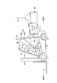
- FIG. 1 is a side view of a battery-type forklift that is Embodiment 1 of the present invention.
- FIG. 2 is a side view of the battery-type forklift shown in FIG. 1 in a state where the battery is loaded and unloaded.
- FIG. 3 is a rear view of the battery-type forklift shown in FIG. 1 in a state where the battery is lifted.
- FIG. 4 is a perspective view of the battery-type forklift shown in FIG. 1 as viewed from the rear.
- FIG. 5 is a perspective view of the battery-type forklift shown in FIG. 1 as seen from the rear, in which the battery hood is tilted and the battery is exposed.
- FIG. 6 is a perspective view of the battery-type forklift shown in FIG. FIG.
- FIG. 7 is a perspective view of the battery-type forklift shown in FIG. 1 as seen from the rear when the battery is taken out from the rear of the vehicle body.
- FIG. 8 is a rear view of a battery-type forklift that is Embodiment 2 of the present invention.
- FIG. 9 is a rear view of a battery-type forklift that is Embodiment 3 of the present invention.
- FIG. 1 show a battery-type forklift that is Embodiment 1 of the present invention.
- the battery-type forklift illustrated here includes front wheels 11 at the front end corners of the vehicle body 10 and rear wheels 12 at the rear end corners of the vehicle body 10, respectively, and is driven by an electric motor (not shown). The vehicle travels using the front wheels 11 as drive wheels.
- a fork 13 for loading and unloading luggage is provided in the front part of the vehicle body 10.
- the fork 13 is supported by a mast 14 provided along the vertical direction, and can be moved up and down along the mast 14 by driving a mast cylinder 15 provided between the fork 13 and the mast 14.
- the mast 14 is attached to the vehicle body 10 so as to be rotatable about a horizontal axis along the left-right direction at the lower end portion thereof, and a tilt cylinder (not shown) is provided between the mast 14 and the vehicle body 10. It is possible to take a forward leaning posture or a backward leaning posture with respect to the vehicle body 10 by driving a tilt cylinder (not shown).
- a counterweight 20 is provided at the rear end of the vehicle body 10.
- the counterweight 20 is a metal weight for balancing when a load is supported by the fork 13, and is disposed in a part of the vehicle body 10 that extends from the part above the rear wheel 12 to the rear end.
- the counterweight 20 is formed so as to have a concave portion opened in the front-rear direction on the upper surface.
- a pair of columnar members 22 project upward from both sides of the weight main body 21 having a flat upper surface, whereby the counterweight 20 having a recess on the upper surface is configured.
- the columnar members 22 are convex portions having guide surfaces 22a that protrude upward from the portions facing each other on both sides of the weight main body 21 and toward the front of the vehicle body 10 and are parallel to each other along the front-rear direction of the vehicle body 10. Yes, and formed integrally with the weight body 21 by casting. 4 and 5 is a resin weight cover that covers the rear surface of the counterweight 20.
- a battery 30 serving as a power source is mounted at the center of the vehicle body 10.
- the battery 30 is configured by accommodating a large number of battery cells 32 in a battery case 31 having a rectangular parallelepiped shape with an upper surface opened.
- the battery case 31 has a dimension along the left-right direction of the vehicle body 10 set slightly smaller than the distance between the guide surfaces 22 a formed on the columnar member 22. It is possible to pass between each other.
- the battery 30 has a battery mounting surface that is set forward of the front surface of the weight body 21 and below the upper surface of the weight body 21 in the vehicle body 10. 16 (FIG. 7).
- the position of the battery mounting surface 16 is set so that the rear end upper part of the battery 30 is interposed between the columnar members 22 and overlaps the counterweight 20. It is.
- a portion of the counterweight 20 that faces the upper rear portion of the battery 30 functions as a contact portion 20 a that restricts the battery 30 from moving rearward of the vehicle body 10 by contacting the battery 30.
- the contact portion 20a may be configured to be planar and contact the battery 30. Alternatively, the contact portion 20a may protrude as a plurality of convex portions and contact the battery 30.
- the respective positions are set so that the front end surface 22 b of the columnar member 22 is positioned forward of the rear end surface 30 a of the battery 30. It is.
- a battery hood 33 is disposed above the battery 30 mounted on the battery mounting surface 16, and a driver seat 34 is disposed on the upper surface of the battery hood 33.
- the battery hood 33 is large enough to cover the upper surface of the battery case 31, and the front end edge of the battery hood 33 is supported by the support bracket 35 of the vehicle body 10 via the support shaft 33 a along the left-right direction of the vehicle body 10. I'm allowed.
- the battery transfer position a height position slightly above the upper surface of 21.
- the support bracket 35 that supports the battery hood 33 is erected upward from a portion located at the front end of the battery mounting surface 16.
- Cushioning material 35a is provided on the surface located at.
- the cushion material 35a is formed in a rectangular parallelepiped shape with a material having high elasticity such as rubber, and is pasted so that the vertical direction is the longitudinal direction.
- the cushion material 35a contacts the upper front portion of the battery case 31 when the battery 30 is mounted on the battery mounting surface 16, and also when the battery 30 is lifted to the battery transfer position. It is arranged so that the vertical direction is long so that it can come into contact with the front surface.
- a top plate 40 is provided in the upper region of the vehicle body 10 as shown in FIGS.
- the top plate 40 is configured by disposing a plurality of crosspieces 42 on a substantially rectangular frame 41 having a size covering the upper area of the driver seat 34, and has a dimension along the left-right direction of the vehicle body 10. Is smaller than the vehicle body 10.
- the top plate 40 is attached to the vehicle body 10 via a pair of front stays 43 and a pair of rear stays 44.
- the front stay 43 extends so as to incline downward from the front end corner of the top plate 40, and each lower end is fixed to the front end of the vehicle body 10. It is.
- the mutual interval (a in FIG. 3) of the front stays 43 is substantially the same over the entire length.
- the rear stay 44 includes a widened portion 44a that projects linearly toward the side so as to gradually separate from the rear end corner of the top plate 40 and a lower end portion of the widened portion 44a. And a stay main body 44b that extends downward substantially vertically and has individual lower ends fixed to the rear end of the vehicle body 10.
- the mutual interval (b in FIG. 3) of the stay main body portions 44b arranged in parallel to each other in the rear stay 44 is substantially the same as the mutual interval of the guide surfaces 22a provided on the columnar member 22, and the battery case 31 and the battery hood 33 can be passed.
- the joining position of the stay main body 44b and the expanding portion 44a is such that the battery hood 33 in the horizontal position does not interfere with the rear stay 44 even when the battery hood 33 is moved forward, and the battery 30 is disposed at the battery transfer position.
- the position is set as high as possible so as not to interfere with the battery case 31.
- the top plate 40 has slits 45 formed therein.
- the slit 45 is formed forward from the rear end of the top plate 40 along the front-rear direction of the vehicle body 10, and is provided so that the front end portion is positioned forward from the midpoint of the front-rear dimension of the battery 30. .
- the battery-type forklift constructed as described above is used for cargo handling work in a state where the battery 30 mounted on the battery mounting surface 16 is covered by the battery hood 33 and the rear surface of the counterweight 20 is covered by the weight cover 23. That is, a desired cargo handling operation can be performed by traveling through the front wheels 11 and the rear wheels 12 by an electric motor (not shown) and lifting and lowering the forks 13 appropriately by an operation of an operator seated on the driver seat 34. It becomes possible.
- a part of the battery 30 is located behind the rear stay 44 that supports the top plate 40 and is mounted on the vehicle body 10 so as to overlap the counterweight 20. Therefore, the weight of the battery 30 effectively functions as a balance weight, and the vehicle body 10 can be configured with the weight of the counterweight 20 itself greatly reduced. Thereby, the weight of the vehicle body 10 can be reduced and the power consumption of the battery 30 can be reduced.
- the battery 30 is mounted at a position above the rear wheel 12, a large dimension along the left-right direction of the battery 30 can be secured. Accordingly, even when the battery 30 having the same weight is mounted, the size along the front-rear direction of the battery 30 is reduced, and the battery 30 can be disposed further rearward of the vehicle body 10 as a balance weight. Can be used more effectively.
- a recess is formed on the upper surface of the counterweight 20 so that the battery case 31 can pass in the front-rear direction, and the rear stay 44 that supports the top plate 40 is formed to have a dimension that allows the battery case 31 to pass therethrough.
- the top plate 40 is formed with a slit 45 extending along the front-rear direction and opening at the rear end. Therefore, as shown in FIG. 5, the weight cover 23 is removed, and the battery hood 33 is moved to the forward tilt position. When the battery hood 33 is lifted by the wire W from this state as shown in FIG. As shown in FIG. 7, the battery 30 can be lowered from the vehicle body 10 if the battery 30 is translated rearward as it is. When the battery 30 is mounted on the vehicle body 10, the reverse operation may be performed.
- the guide surfaces 22a formed on the columnar members 22 move the battery 30 in the front-rear direction of the vehicle body 10. Become a guide. Therefore, there is no possibility that the moving battery 30 will swing in the left-right direction of the vehicle body and collide with other parts, or that both may be damaged.
- the support bracket 35 that supports the battery hood 33 is provided with a cushioning material 35a, even if the battery case 31 collides with the support bracket 35 due to the momentum when the battery 30 is mounted, both of them are seriously damaged. There is no fear of coming.
- a pair of columnar members 22 is provided only on the counterweight 20 and the battery 30 is guided between these columnar members 22, but the present invention is not necessarily limited to this.
- the protrusion 122 extending along the front-rear direction is provided at the center of the upper surface of the counterweight 120, while the protrusion 122 is inserted into the bottom of the battery case 131.
- the guide groove 131a which can be formed is formed. Also in the second embodiment, by inserting the protrusion 122 into the guide groove 131a, the protrusion 122 and the guide groove 131a function as a guide when the battery 30 is moved in the front-rear direction of the vehicle body 10. Therefore, there is no possibility that the moving battery 30 will swing and collide with other parts, or that both may be damaged.
- a guide groove 222 is provided along the front-rear direction in the center portion of the upper surface of the counterweight 220, while the protruding portion that can be inserted into the guide groove 222 on the bottom surface of the battery case 231. 231a is formed. Also in the third embodiment, the protrusions 231a and the guide grooves 222 function as guides when the battery 30 is moved in the front-rear direction of the vehicle body 10 by inserting the protrusions 231a into the guide grooves 222. Therefore, there is no possibility that the moving battery 30 will swing and collide with other parts, or that both may be damaged.
- Embodiment 2 and Embodiment 3 about the structure similar to Embodiment 1, the same code
- Embodiments 1 to 3 described above a battery in which a large number of battery cells are housed in a battery case is illustrated, but the configuration of the battery is not limited to this.
Landscapes
- Engineering & Computer Science (AREA)
- Transportation (AREA)
- Structural Engineering (AREA)
- Civil Engineering (AREA)
- Life Sciences & Earth Sciences (AREA)
- Geology (AREA)
- Mechanical Engineering (AREA)
- Chemical & Material Sciences (AREA)
- Combustion & Propulsion (AREA)
- Forklifts And Lifting Vehicles (AREA)
- Arrangement Or Mounting Of Propulsion Units For Vehicles (AREA)
Abstract
Description
13 フォーク
16 バッテリ載置面
20 カウンタウエイト
21 ウエイト本体
20a 当接部
22 柱状部材
22a ガイド面
22b 前端面
30 バッテリ
30a 後端面
40 天板
44 リヤステー
120 カウンタウエイト
122 突条部
131 バッテリケース
131a ガイド溝
220 カウンタウエイト
222 ガイド溝
231 バッテリケース
231a 突条部
Claims (5)
- 車体の前方部に配設したフォークと、前記車体の後方部に配設したカウンタウエイトとを備え、前記車体に搭載したバッテリの電力によって走行するバッテリ式フォークリフトにおいて、
前記車体の後方に向けて取出可能となる状態で前記車体にバッテリを搭載するとともに、前記カウンタウエイトに、前記バッテリを取り出す際に前記バッテリの車体左右方向への揺れを防止するとともに、車体の前後方向に沿ったバッテリの移動を案内するガイド手段を設けたことを特徴とするバッテリ式フォークリフト。 - 前記カウンタウエイトの左右両側に上方に向けて突出する柱状部材を備え、前記ガイド手段は前記柱状部材であり、これら柱状部材の間において車体の前後方向に沿ったバッテリの移動を案内することを特徴とする請求項1に記載のバッテリ式フォークリフト。
- 前記柱状部材は、前記カウンタウエイトと一体で鋳物により形成されることを特徴とする請求項2に記載のバッテリ式フォークリフト。
- 前記カウンタウエイトには、前記バッテリを前記車体に搭載した際に前記バッテリの車体後方への移動を規制する当接部が設けられることを特徴とする請求項2に記載のバッテリ式フォークリフト。
- 前記バッテリを前記車体に搭載した状態で、前記柱状部材の前端面が前記バッテリの後端面よりも前方に位置することを特徴とする請求項2に記載のバッテリ式フォークリフト。
Priority Applications (4)
| Application Number | Priority Date | Filing Date | Title |
|---|---|---|---|
| JP2012531165A JP5090582B1 (ja) | 2011-04-08 | 2012-03-13 | バッテリ式フォークリフト |
| US13/698,461 US9162858B2 (en) | 2011-04-08 | 2012-03-13 | Battery-powered forklift |
| DE112012000018T DE112012000018T5 (de) | 2011-04-08 | 2012-03-13 | Batteriegabelstapler |
| CN201280001348.1A CN102906003B (zh) | 2011-04-08 | 2012-03-13 | 蓄电池式叉车 |
Applications Claiming Priority (2)
| Application Number | Priority Date | Filing Date | Title |
|---|---|---|---|
| JP2011086786 | 2011-04-08 | ||
| JP2011-086786 | 2011-04-08 |
Publications (1)
| Publication Number | Publication Date |
|---|---|
| WO2012137581A1 true WO2012137581A1 (ja) | 2012-10-11 |
Family
ID=46968985
Family Applications (1)
| Application Number | Title | Priority Date | Filing Date |
|---|---|---|---|
| PCT/JP2012/056418 WO2012137581A1 (ja) | 2011-04-08 | 2012-03-13 | バッテリ式フォークリフト |
Country Status (5)
| Country | Link |
|---|---|
| US (1) | US9162858B2 (ja) |
| JP (1) | JP5090582B1 (ja) |
| CN (1) | CN102906003B (ja) |
| DE (1) | DE112012000018T5 (ja) |
| WO (1) | WO2012137581A1 (ja) |
Families Citing this family (4)
| Publication number | Priority date | Publication date | Assignee | Title |
|---|---|---|---|---|
| CN104097695A (zh) * | 2014-06-30 | 2014-10-15 | 苏州先锋物流装备科技有限公司 | 一种方便拆装电瓶的带驾驶室的牵引车 |
| US10112471B2 (en) * | 2016-05-18 | 2018-10-30 | Sharp Kabushiki Kaisha | Battery-driven traveling device |
| CN107539924B (zh) * | 2017-09-05 | 2023-05-02 | 宁波海天驱动科技有限公司 | 一种兼具侧叉及后叉式蓄电池更换方式的电动叉车 |
| JP7405684B2 (ja) | 2020-04-30 | 2023-12-26 | 矢崎総業株式会社 | 蓄熱材組成物及び建築物の冷暖房用の蓄熱システム |
Citations (4)
| Publication number | Priority date | Publication date | Assignee | Title |
|---|---|---|---|---|
| JPS5231171U (ja) * | 1975-08-27 | 1977-03-04 | ||
| JPS58161994U (ja) * | 1982-04-26 | 1983-10-28 | 小松フオ−クリフト株式会社 | バツテリ式フオ−クリフトのバツテリ取付装置 |
| JP2005041656A (ja) * | 2003-07-23 | 2005-02-17 | Tcm Corp | 電動車両用バッテリボックスの移動案内装置 |
| JP2010047192A (ja) * | 2008-08-25 | 2010-03-04 | Nippon Yusoki Co Ltd | スライド式バッテリーのストッパー |
Family Cites Families (26)
| Publication number | Priority date | Publication date | Assignee | Title |
|---|---|---|---|---|
| US3610359A (en) * | 1969-11-17 | 1971-10-05 | Hyster Co | Truck with movable control panel |
| US3721353A (en) | 1970-12-14 | 1973-03-20 | Clark Equipment Co | Combined battery case,counterweight and overhead guard |
| US4026378A (en) | 1975-11-28 | 1977-05-31 | Clark Equipment Company | Electric lift truck body construction |
| US4711467A (en) * | 1986-01-13 | 1987-12-08 | Clark Equipment Company | Method and means for lift truck assembly and servicing |
| US4834424A (en) * | 1986-10-15 | 1989-05-30 | Clark Equipment Company | Lift truck |
| US5360307A (en) * | 1992-12-07 | 1994-11-01 | Windsor Industries | Battery transfer technique for vehicle |
| JPH0717265A (ja) * | 1993-07-06 | 1995-01-20 | Nippon Home Keizai Kenkyusho:Kk | 電気自動車動力用二次電池の自動車への装架装置 |
| JPH08282414A (ja) * | 1995-04-17 | 1996-10-29 | Toyota Autom Loom Works Ltd | 産業車両 |
| US5760569A (en) * | 1997-02-26 | 1998-06-02 | Chase, Jr.; Robert B. | Replaceable battery module for electric vehicle |
| CN2297437Y (zh) | 1997-06-09 | 1998-11-18 | 山东光明机器厂 | U型蓄电池组平衡重式低座椅叉车 |
| JP2000226194A (ja) * | 1999-02-08 | 2000-08-15 | Toyota Autom Loom Works Ltd | バッテリ式産業車両のフレーム構造 |
| JP2001302192A (ja) * | 2000-04-20 | 2001-10-31 | Nippon Yusoki Co Ltd | フォークリフト |
| JP2001316091A (ja) * | 2000-05-12 | 2001-11-13 | Nippon Yusoki Co Ltd | バッテリフォークリフト |
| JP2002308582A (ja) | 2001-04-18 | 2002-10-23 | Mitsubishi Heavy Ind Ltd | バッテリ車におけるバッテリの収納構造 |
| JP2003118990A (ja) | 2001-10-12 | 2003-04-23 | Komatsu Forklift Co Ltd | 産業車両における燃料ガス用カウンターウエイト装置 |
| JP2005324643A (ja) * | 2004-05-13 | 2005-11-24 | Toyota Industries Corp | バッテリストッパー |
| JP4142692B2 (ja) | 2006-02-07 | 2008-09-03 | 株式会社竹内製作所 | 作業車のバッテリ配置構造 |
| DE102006031461A1 (de) * | 2006-07-07 | 2008-01-10 | Jungheinrich Aktiengesellschaft | Batteriewechselsystem für ein batteriebetriebenes Flurförderzeug |
| DE102007031149A1 (de) * | 2007-07-05 | 2009-01-08 | Jungheinrich Aktiengesellschaft | Flurförderzeug, insbesondere Gabelstapler |
| GB2454067B (en) | 2007-10-04 | 2012-05-16 | Linde Material Handling Gmbh | Fork-lift truck with an electric battery drive system |
| DE102008004653A1 (de) | 2007-10-04 | 2009-04-09 | Linde Material Handling Gmbh | Gabelstapler mit einem batterie-elektrischen Antriebssystem |
| JP2009274651A (ja) * | 2008-05-16 | 2009-11-26 | Toyota Industries Corp | ハイブリッド産業車両 |
| DE102009035394A1 (de) | 2009-07-30 | 2011-02-03 | Jungheinrich Aktiengesellschaft | Verriegelungsvorrichtung für einen Batterieblock für ein Flurförderzeug |
| CN101811652B (zh) * | 2010-04-01 | 2012-01-25 | 张波 | 电动叉车 |
| DE112012000063T5 (de) * | 2011-04-08 | 2013-08-22 | Komatsu Ltd. | Batterieangetriebener Gabelstapler |
| CN202704956U (zh) | 2012-06-14 | 2013-01-30 | 深圳霸特尔防爆科技有限公司 | 平衡重式防爆交流叉车 |
-
2012
- 2012-03-13 CN CN201280001348.1A patent/CN102906003B/zh not_active Expired - Fee Related
- 2012-03-13 WO PCT/JP2012/056418 patent/WO2012137581A1/ja active Application Filing
- 2012-03-13 DE DE112012000018T patent/DE112012000018T5/de not_active Withdrawn
- 2012-03-13 JP JP2012531165A patent/JP5090582B1/ja active Active
- 2012-03-13 US US13/698,461 patent/US9162858B2/en not_active Expired - Fee Related
Patent Citations (4)
| Publication number | Priority date | Publication date | Assignee | Title |
|---|---|---|---|---|
| JPS5231171U (ja) * | 1975-08-27 | 1977-03-04 | ||
| JPS58161994U (ja) * | 1982-04-26 | 1983-10-28 | 小松フオ−クリフト株式会社 | バツテリ式フオ−クリフトのバツテリ取付装置 |
| JP2005041656A (ja) * | 2003-07-23 | 2005-02-17 | Tcm Corp | 電動車両用バッテリボックスの移動案内装置 |
| JP2010047192A (ja) * | 2008-08-25 | 2010-03-04 | Nippon Yusoki Co Ltd | スライド式バッテリーのストッパー |
Also Published As
| Publication number | Publication date |
|---|---|
| CN102906003A (zh) | 2013-01-30 |
| DE112012000018T5 (de) | 2013-08-22 |
| US20140238780A1 (en) | 2014-08-28 |
| JPWO2012137581A1 (ja) | 2014-07-28 |
| US9162858B2 (en) | 2015-10-20 |
| CN102906003B (zh) | 2014-05-21 |
| JP5090582B1 (ja) | 2012-12-05 |
Similar Documents
| Publication | Publication Date | Title |
|---|---|---|
| JP5162053B2 (ja) | バッテリ式フォークリフト | |
| JP5498623B1 (ja) | 作業機械用バッテリケース、作業機械用バッテリユニット、バッテリ式作業機械及びバッテリ式フォークリフト | |
| EP2933859B1 (en) | Battery pack and industrial vehicle | |
| US8763743B2 (en) | Battery pack mounting structure for electric vehicle | |
| JP5090582B1 (ja) | バッテリ式フォークリフト | |
| EP2883730B1 (en) | Industrial vehicle | |
| TWI805835B (zh) | 搬送車 | |
| CN102673359A (zh) | 用于电动车辆的高压电缆布线结构 | |
| JP2019114469A (ja) | 燃料電池車両 | |
| JP7025226B2 (ja) | 旋回フレーム及び建設機械 | |
| JP2013239261A (ja) | 荷役搬送用産業車両 | |
| JP6155672B2 (ja) | 電池パック | |
| JP6103192B2 (ja) | 電池パック | |
| CN111439103B (zh) | 车辆下部结构 | |
| JP5915367B2 (ja) | 荷役搬送用産業車両 | |
| JP2015002150A (ja) | フォークリフト用蓄電モジュール | |
| JP6577422B2 (ja) | 荷役作業車 | |
| JP7142079B2 (ja) | 作業車両 | |
| JP2011131826A (ja) | 車両のバッテリ搭載構造 | |
| JP2003182990A (ja) | バッテリ式フォークリフトトラック | |
| JP5869413B2 (ja) | フォークリフト | |
| JP2009208522A (ja) | バッテリ搭載構造 | |
| JP2003238083A (ja) | バッテリ式フォークリフト |
Legal Events
| Date | Code | Title | Description |
|---|---|---|---|
| WWE | Wipo information: entry into national phase |
Ref document number: 201280001348.1 Country of ref document: CN |
|
| ENP | Entry into the national phase |
Ref document number: 2012531165 Country of ref document: JP Kind code of ref document: A |
|
| WWE | Wipo information: entry into national phase |
Ref document number: 13698461 Country of ref document: US Ref document number: 1120120000188 Country of ref document: DE Ref document number: 112012000018 Country of ref document: DE |
|
| 121 | Ep: the epo has been informed by wipo that ep was designated in this application |
Ref document number: 12768576 Country of ref document: EP Kind code of ref document: A1 |
|
| 122 | Ep: pct application non-entry in european phase |
Ref document number: 12768576 Country of ref document: EP Kind code of ref document: A1 |