WO2012053516A1 - Electronic device, control method and control program - Google Patents
Electronic device, control method and control program Download PDFInfo
- Publication number
- WO2012053516A1 WO2012053516A1 PCT/JP2011/073947 JP2011073947W WO2012053516A1 WO 2012053516 A1 WO2012053516 A1 WO 2012053516A1 JP 2011073947 W JP2011073947 W JP 2011073947W WO 2012053516 A1 WO2012053516 A1 WO 2012053516A1
- Authority
- WO
- WIPO (PCT)
- Prior art keywords
- function
- display unit
- displayed
- display
- icon
- Prior art date
Links
Images


Classifications
-
- G—PHYSICS
- G06—COMPUTING; CALCULATING OR COUNTING
- G06F—ELECTRIC DIGITAL DATA PROCESSING
- G06F3/00—Input arrangements for transferring data to be processed into a form capable of being handled by the computer; Output arrangements for transferring data from processing unit to output unit, e.g. interface arrangements
- G06F3/01—Input arrangements or combined input and output arrangements for interaction between user and computer
- G06F3/03—Arrangements for converting the position or the displacement of a member into a coded form
- G06F3/041—Digitisers, e.g. for touch screens or touch pads, characterised by the transducing means
-
- G—PHYSICS
- G06—COMPUTING; CALCULATING OR COUNTING
- G06F—ELECTRIC DIGITAL DATA PROCESSING
- G06F3/00—Input arrangements for transferring data to be processed into a form capable of being handled by the computer; Output arrangements for transferring data from processing unit to output unit, e.g. interface arrangements
- G06F3/01—Input arrangements or combined input and output arrangements for interaction between user and computer
- G06F3/048—Interaction techniques based on graphical user interfaces [GUI]
- G06F3/0487—Interaction techniques based on graphical user interfaces [GUI] using specific features provided by the input device, e.g. functions controlled by the rotation of a mouse with dual sensing arrangements, or of the nature of the input device, e.g. tap gestures based on pressure sensed by a digitiser
- G06F3/0488—Interaction techniques based on graphical user interfaces [GUI] using specific features provided by the input device, e.g. functions controlled by the rotation of a mouse with dual sensing arrangements, or of the nature of the input device, e.g. tap gestures based on pressure sensed by a digitiser using a touch-screen or digitiser, e.g. input of commands through traced gestures
- G06F3/04883—Interaction techniques based on graphical user interfaces [GUI] using specific features provided by the input device, e.g. functions controlled by the rotation of a mouse with dual sensing arrangements, or of the nature of the input device, e.g. tap gestures based on pressure sensed by a digitiser using a touch-screen or digitiser, e.g. input of commands through traced gestures for inputting data by handwriting, e.g. gesture or text
-
- G—PHYSICS
- G06—COMPUTING; CALCULATING OR COUNTING
- G06F—ELECTRIC DIGITAL DATA PROCESSING
- G06F3/00—Input arrangements for transferring data to be processed into a form capable of being handled by the computer; Output arrangements for transferring data from processing unit to output unit, e.g. interface arrangements
- G06F3/01—Input arrangements or combined input and output arrangements for interaction between user and computer
- G06F3/048—Interaction techniques based on graphical user interfaces [GUI]
- G06F3/0481—Interaction techniques based on graphical user interfaces [GUI] based on specific properties of the displayed interaction object or a metaphor-based environment, e.g. interaction with desktop elements like windows or icons, or assisted by a cursor's changing behaviour or appearance
- G06F3/04817—Interaction techniques based on graphical user interfaces [GUI] based on specific properties of the displayed interaction object or a metaphor-based environment, e.g. interaction with desktop elements like windows or icons, or assisted by a cursor's changing behaviour or appearance using icons
-
- G—PHYSICS
- G06—COMPUTING; CALCULATING OR COUNTING
- G06F—ELECTRIC DIGITAL DATA PROCESSING
- G06F3/00—Input arrangements for transferring data to be processed into a form capable of being handled by the computer; Output arrangements for transferring data from processing unit to output unit, e.g. interface arrangements
- G06F3/01—Input arrangements or combined input and output arrangements for interaction between user and computer
- G06F3/048—Interaction techniques based on graphical user interfaces [GUI]
- G06F3/0481—Interaction techniques based on graphical user interfaces [GUI] based on specific properties of the displayed interaction object or a metaphor-based environment, e.g. interaction with desktop elements like windows or icons, or assisted by a cursor's changing behaviour or appearance
- G06F3/0482—Interaction with lists of selectable items, e.g. menus
-
- G—PHYSICS
- G06—COMPUTING; CALCULATING OR COUNTING
- G06F—ELECTRIC DIGITAL DATA PROCESSING
- G06F3/00—Input arrangements for transferring data to be processed into a form capable of being handled by the computer; Output arrangements for transferring data from processing unit to output unit, e.g. interface arrangements
- G06F3/01—Input arrangements or combined input and output arrangements for interaction between user and computer
- G06F3/048—Interaction techniques based on graphical user interfaces [GUI]
- G06F3/0487—Interaction techniques based on graphical user interfaces [GUI] using specific features provided by the input device, e.g. functions controlled by the rotation of a mouse with dual sensing arrangements, or of the nature of the input device, e.g. tap gestures based on pressure sensed by a digitiser
- G06F3/0488—Interaction techniques based on graphical user interfaces [GUI] using specific features provided by the input device, e.g. functions controlled by the rotation of a mouse with dual sensing arrangements, or of the nature of the input device, e.g. tap gestures based on pressure sensed by a digitiser using a touch-screen or digitiser, e.g. input of commands through traced gestures
- G06F3/04886—Interaction techniques based on graphical user interfaces [GUI] using specific features provided by the input device, e.g. functions controlled by the rotation of a mouse with dual sensing arrangements, or of the nature of the input device, e.g. tap gestures based on pressure sensed by a digitiser using a touch-screen or digitiser, e.g. input of commands through traced gestures by partitioning the display area of the touch-screen or the surface of the digitising tablet into independently controllable areas, e.g. virtual keyboards or menus
-
- H—ELECTRICITY
- H04—ELECTRIC COMMUNICATION TECHNIQUE
- H04M—TELEPHONIC COMMUNICATION
- H04M1/00—Substation equipment, e.g. for use by subscribers
- H04M1/72—Mobile telephones; Cordless telephones, i.e. devices for establishing wireless links to base stations without route selection
- H04M1/724—User interfaces specially adapted for cordless or mobile telephones
- H04M1/72448—User interfaces specially adapted for cordless or mobile telephones with means for adapting the functionality of the device according to specific conditions
- H04M1/72454—User interfaces specially adapted for cordless or mobile telephones with means for adapting the functionality of the device according to specific conditions according to context-related or environment-related conditions
-
- G—PHYSICS
- G06—COMPUTING; CALCULATING OR COUNTING
- G06F—ELECTRIC DIGITAL DATA PROCESSING
- G06F2203/00—Indexing scheme relating to G06F3/00 - G06F3/048
- G06F2203/048—Indexing scheme relating to G06F3/048
- G06F2203/04803—Split screen, i.e. subdividing the display area or the window area into separate subareas
-
- H—ELECTRICITY
- H04—ELECTRIC COMMUNICATION TECHNIQUE
- H04M—TELEPHONIC COMMUNICATION
- H04M2250/00—Details of telephonic subscriber devices
- H04M2250/16—Details of telephonic subscriber devices including more than one display unit
-
- H—ELECTRICITY
- H04—ELECTRIC COMMUNICATION TECHNIQUE
- H04M—TELEPHONIC COMMUNICATION
- H04M2250/00—Details of telephonic subscriber devices
- H04M2250/22—Details of telephonic subscriber devices including a touch pad, a touch sensor or a touch detector
Definitions
- the present invention relates to an electronic device, a control method, and a control program.
- touch panels have been widely used to realize small electronic devices that can be operated intuitively and do not include devices that require a physically large area such as a keyboard.
- Patent Document 1 there are two touch panels, and the touch panel is displaced to either an open state in which two touch panels are exposed or a closed state in which only one touch panel is exposed.
- a telephone terminal that makes a call in response to a displacement to a state.
- Patent Document 1 The technique described in Patent Document 1 described above can improve the convenience of the user for operations related to calls, but does not particularly take into account operations related to other functions of electronic devices.
- electronic devices are provided with a wide variety of functions, and there is a demand for improving the convenience of users for the operation of functions other than calls.
- the present invention has been made in view of the above, and an object of the present invention is to provide an electronic device, a control method, and a control program that can improve user convenience.
- an electronic device has a first housing having a first display portion, a second housing having a second display portion, and the first display portion exposed to the outside. And detecting the first form in which the second display unit is covered by the first housing and the second form in which the first display unit and the second display unit are exposed to the outside. When the detection unit and the detection unit detect that the electronic device has changed from the first form to the second form, a selection is made from among the objects displayed on the first display unit. A control unit that activates a function corresponding to the object being displayed and displays a screen corresponding to the function on the second display unit.
- a control method controls an electronic device including a first casing having a first display section, a second casing having a second display section, and a detection section.
- the electronic device may be configured such that the first display unit is exposed to the outside and the second display unit is covered with the first casing by the detection unit. Detecting that the display unit and the second display unit have changed to the second form exposed to the outside, and when detecting that the electronic device has changed to the second form, Starting a function corresponding to the selected object among the objects displayed on the first display unit, and displaying a screen corresponding to the function on the second display unit.
- a control program is provided in an electronic device including a first casing having a first display section, a second casing having a second display section, and a detection section. From the first form in which the electronic device has the first display unit exposed to the outside and the second display unit is covered with the first housing by the detection unit, the first display unit and the first display unit The step of detecting that the second display unit has changed to the second form exposed to the outside, and the first display unit when it is detected that the electronic device has changed to the second form A function corresponding to the selected object among the objects displayed on the screen is activated, and a step of displaying a screen corresponding to the function on the second display unit is executed.
- the electronic device, the control method, and the control program according to the present invention can improve user convenience.
- FIG. 1 is a perspective view of a mobile phone terminal in a first form.
- FIG. 2 is a perspective view of the mobile phone terminal in the second embodiment.
- FIG. 3 is a diagram illustrating an example in which a function is activated in conjunction with a change in form.
- FIG. 4 is a diagram illustrating an example in which a function is interrupted in conjunction with a change in form.
- FIG. 5 is a diagram illustrating an example of resuming a function in conjunction with a change in form.
- FIG. 6 is a diagram illustrating an example in which the interrupted function is resumed on the first display unit.
- FIG. 7 is a diagram illustrating an example of displaying an explanation regarding icons.
- FIG. 8 is a diagram illustrating another example in which an explanation regarding icons is displayed.
- FIG. 1 is a perspective view of a mobile phone terminal in a first form.
- FIG. 2 is a perspective view of the mobile phone terminal in the second embodiment.
- FIG. 3 is a diagram illustrating an example
- FIG. 9 is a block diagram showing a functional configuration of the mobile phone terminal according to the first embodiment.
- FIG. 10 is a diagram illustrating an example of icon data.
- FIG. 11 is a flowchart illustrating a processing procedure when an operation on an icon is detected on the first display unit.
- FIG. 12 is a flowchart showing a processing procedure when the form of the mobile phone terminal is changed.
- FIG. 13 is a diagram illustrating an example of control when a function is activated in a state where other functions are not activated.
- FIG. 14A is a diagram illustrating an example of control when a function is activated in a state where one function is activated.
- FIG. 14B is a diagram illustrating another example of control when a function is activated in a state where one function is activated.
- FIG. 14A is a diagram illustrating an example of control when a function is activated in a state where one function is activated.
- FIG. 14B is a diagram illustrating another example of control when a
- FIG. 14C is a diagram illustrating another example of control when a function is activated in a state where one function is activated.
- FIG. 15 is a diagram illustrating an example of control when a function is activated in a state where two functions are activated.
- FIG. 16 is a diagram illustrating an example of control in the case where the suspended function is resumed.
- FIG. 17 is a diagram illustrating another example of the control in the case where the suspended function is resumed.
- FIG. 18 is a diagram illustrating an example of control in a case where the function being executed is terminated.
- FIG. 19 is a block diagram showing a functional configuration of the mobile phone terminal according to the second embodiment.
- FIG. 20 is a diagram illustrating an example of execution status data.
- FIG. 21 is a flowchart illustrating the operation of the control unit when contact with an icon corresponding to an executable function is detected.
- FIG. 22 is a diagram illustrating an example of control when a function is activated in a state where other functions are not activated.
- FIG. 23 is a diagram illustrating an example of control when a function is activated in a state where one function is activated.
- a mobile phone terminal will be described as an example of an electronic device.
- the application target of the present invention is not limited to a mobile phone terminal, and various devices including a touch panel, such as PHS (Personal Handyphone System), PDA
- PHS Personal Handyphone System
- PDA Personal Digital Assistant
- FIG. 1 is a perspective view of the mobile phone terminal 1 in the first form
- FIG. 2 is a perspective view of the mobile phone terminal 1 in the second form.
- the mobile phone terminal 1 has a first housing 1A and a second housing 1B.
- the first housing 1A is configured to be relatively slidable in the direction of arrow A with respect to the second housing 1B.
- the first housing 1A has a touch panel 2 on the surface opposite to the surface facing the second housing 1B.
- the second housing 1B has a touch panel 3 on the surface facing the first housing 1A.
- the touch panel 2 and the touch panel 3 display characters, figures, images, and the like, and detect various operations performed on the touch panel by a user using a finger, a stylus, or the like (hereinafter simply referred to as “finger”).
- the touch panel 3 is covered and hidden by the first casing 1A in the first form in which the first casing 1A and the second casing 1B overlap, and the first casing 1A slides in the direction of the arrow A. In the second form, it is exposed to the outside.
- the first form is a form suitable for the user to carry the mobile phone terminal 1.
- the user refers to information displayed on the touch panel 2 or operates the touch panel 2 with a finger. You can enter information.
- the second form is a form suitable for the user to use the mobile phone terminal 1, and the user can refer to more information by using the touch panel 2 and the touch panel 3 together.
- the touch panel 2 that is always exposed to the outside is referred to as a first display unit.
- the touch panel 3 that is covered with the first casing 1A and exposed to the outside in the second form.
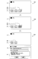
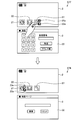
- FIG. 3 is a diagram illustrating an example in which a function is activated in conjunction with a change in form.
- FIG. 4 is a diagram illustrating an example in which a function is interrupted in conjunction with a change in form.
- FIG. 5 is a diagram illustrating an example of resuming a function in conjunction with a change in form.
- step S11 shown in FIG. 3 the mobile phone terminal 1 is in the first form, and a standby screen in which icons 21 and 22 are arranged is displayed on the first display unit.
- the icon 21 is an object used for newly starting a WEB browsing function
- the icon 22 is an object used for newly starting an electronic mail function.
- the standby screen is a screen in a state waiting for incoming / outgoing calls, or a screen in a state waiting for starting an application program.
- the standby screen is a screen before the screen is changed to a screen for using various functions provided by the mobile phone terminal 1 (hereinafter also referred to as “function screen”).
- the standby screen may be called a desktop screen, a home screen, or wallpaper, for example.
- a plain screen is displayed as the standby screen, but image data and animation data may be displayed as the standby screen.
- a dynamically changing part such as a calendar or a clock may be included.
- step S12 when the user performs a single tap operation on the icon 22, the mobile phone terminal 1 places the icon 22 in a selected state.
- the mobile phone terminal 1 makes the selected icon 22 distinguishable from other icons by, for example, reducing the brightness.
- the single tap operation is an operation in which a finger is touched on the touch panel and then immediately released once so as to tap an icon or the like.
- the cellular phone terminal 1 activates the e-mail function corresponding to the icon 22 in the selected state on the second display unit.
- starting the electronic mail function on the second display unit means starting the electronic mail function and displaying a screen provided by the electronic mail function on the second display unit.
- a screen provided by the electronic mail function is, for example, a mail creation screen 31.
- the mobile phone terminal 1 changes from the first form to the second form, if there is an icon selected in the first display unit, the mobile phone terminal 1 has a function corresponding to the icon. 2 is activated on the display unit. For this reason, if the user wants to activate any function on the second display unit while carrying the mobile phone terminal 1 in the first form, the user can select an icon corresponding to the function. 1 is selected. In this way, the user activates the desired function on the second display unit in conjunction with the operation of transforming the mobile phone terminal 1 into the second form and exposing the second display unit. be able to.
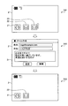
- step S22 the cellular phone terminal 1 interrupts the e-mail function activated on the second display unit, and displays an icon 23 indicating that the e-mail function is suspended on the first display unit. Display.
- the icon 23 has the same appearance as the icon 22 for starting the e-mail function, and “! (Exclamation mark)” is added so that it can be identified that the corresponding function is suspended. .
- the addition of “!” Is an example, and an icon indicating a suspended function may be distinguished from an icon for newly starting a function in some way. For example, the thumbnail image of the second display unit immediately before the interruption may be displayed as the icon 23.
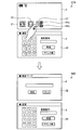
- step S31 of FIG. 5 the user wants to resume the suspended function while the icon 23 corresponding to the suspended function is displayed on the first display unit. Shall. In this case, the user performs a single tap operation on the icon 23 as step S32. When a single tap operation is performed on the icon 23, the mobile phone terminal 1 places the icon 23 in a selected state.
- the mobile phone terminal 1 When the user changes the mobile phone terminal 1 from the first form to the second form in step S33 when the icon 23 is in the selected state, the mobile phone terminal 1 has an e-mail function corresponding to the icon 23. Is resumed on the second display section. In addition, the cellular phone terminal 1 deletes the icon 23 from the first display unit when the electronic mail function is resumed.
- the mobile phone terminal 1 changes from the first form to the second form
- the icon corresponding to the suspended function is in the selected state on the first display unit
- the icon is displayed.
- the function corresponding to is restarted on the second display unit.
- the user wants to resume the function activated on the second display unit, the user selects the icon corresponding to the function on the first display unit. By doing so, the user resumes the desired function on the second display unit in conjunction with the operation of transforming the mobile phone terminal 1 into the second form and exposing the second display unit. be able to.
- the user performs a double-tap operation on the icon 23 while the icon 23 corresponding to the interrupted function is displayed on the first display unit.
- the double-tap operation is an operation in which a finger is brought into contact with the touch panel and then released immediately, so that the user taps an icon or the like twice.
- the cellular phone terminal 1 restarts the electronic mail function corresponding to the icon 23 in the first display unit instead of the second display unit in step S42. At this time, the cellular phone terminal 1 deletes the icon 23 from the first display unit as the electronic mail function is resumed. As a result, after the user ends the electronic mail function, the icon 23 is not displayed on the first display unit as shown in step S43.
- the user can know the details of the displayed icon by performing a predetermined operation. For example, as shown in step S51 of FIG. 7, the user performs a long tap operation on the icon 22 while the icon 22 corresponding to the e-mail function is displayed on the first display unit.
- the long tap operation refers to an operation of bringing a finger into contact with the touch panel for a longer time than a predetermined time so as to push an icon or the like.
- the cellular phone terminal 1 sets the icon 22 in a selected state, and displays a balloon 24 or the like indicating that the function corresponding to the icon 22 is an e-mail function on the first display unit.
- the user is notified of what the function corresponding to the icon 22 is.
- the timing at which the balloon 24 is displayed may be a timing at which the touch of the finger on the touch panel becomes longer than a predetermined time.
- the balloon 24 may be deleted when the finger is separated from the touch panel.
- the timing at which the balloon 24 is displayed may be the timing at which the finger leaves the touch panel.
- the balloon 24 may be deleted when another predetermined time elapses after the finger leaves the touch panel.
- step S61 of FIG. 8 the user performs a long tap operation on the icon 23 while the icon 23 corresponding to the suspended email function is displayed on the first display unit.
- the cellular phone terminal 1 sets the icon 23 to the selected state, and the function corresponding to the icon 23 is an e-mail function.
- the user is notified of what the function corresponding to the icon 23 is and what processing was interrupted during execution.
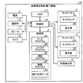
- FIG. 9 is a block diagram showing a functional configuration of the mobile phone terminal 1.
- the mobile phone terminal 1 includes a touch panel 2, a touch panel 3, a form detection unit 4, a power supply unit 5, a communication unit 6, a speaker 7, a microphone 8, a storage unit 9, and a control.
- the touch panel 2 is provided in the first casing 1A and the touch panel 3 is provided in the second casing 1B, each part is in either the first casing 1A or the second casing 1B. It may be provided.
- the touch panel 2 includes a display unit 2B and a touch sensor 2A superimposed on the display unit 2B.
- the touch panel 3 includes a display unit 3B and a touch sensor 3A superimposed on the display unit 3B.
- the touch sensor 2 ⁇ / b> A and the touch sensor 3 ⁇ / b> A detect various operations performed on the surface using a finger together with the position where the operation is performed.
- the operations detected by the touch sensor 2A and the touch sensor 3A include a single tap operation, a double tap operation, a long tap operation, and the like.
- the display unit 2B and the display unit 3B are composed of, for example, a liquid crystal display (LCD) or an organic EL (Organic Electro-Luminescence) panel, and display characters, figures, images, and the like.
- the form detection unit 4 detects whether the mobile phone terminal 1 is in the first form or the second form.
- the form detection unit 4 detects the form of the mobile phone terminal 1 using, for example, a mechanical switch provided on a surface where the first housing 1A and the second housing 1B face each other.
- the power supply unit 5 supplies power obtained from a storage battery or an external power supply to each functional unit of the mobile phone terminal 1 including the control unit 10.
- the communication unit 6 establishes a radio signal line by a CDMA system or the like with a base station via a channel assigned by the base station, and performs telephone communication and information communication with the base station.
- the speaker 7 outputs the other party's voice, ringtone, and the like in telephone communication.
- the microphone 8 converts the voice of the user or the like into an electrical signal.
- the storage unit 9 includes at least one non-transitory storage device such as a nonvolatile memory (ROM, EPROM, memory card, solid state device, etc.), magnetic storage device, optical storage device, etc. Save programs and data used for processing.
- the storage unit 9 includes a mail program 9A for realizing an electronic mail function, a browser program 9B for realizing a WEB browsing function, a control program 9C for realizing control of the functions as described above, And the icon data 9D in which information related to icons displayed on the screen is stored is stored.
- the storage unit 9 stores other programs and data such as an operating system program for realizing basic functions of the mobile phone terminal 1 and address book data in which names, telephone numbers, mail addresses, etc. are registered. Is done.
- the icon data 9D will be described with reference to FIG.
- FIG. 10 is a diagram illustrating an example of the icon data 9D.
- the icon data 9D has items such as ID, corresponding function, display position, pictogram, suspended process, and selection.
- ID item an icon identification number is stored.
- corresponding function item information for specifying a function corresponding to the icon is stored.
- display position item information for specifying the position where the icon is displayed is stored.
- the suspended process item stores a process number which is the actual state of the suspended function when the corresponding function is suspended.
- a process is a program that has been loaded into the RAM 11 by the control unit 10 and has become executable.
- the suspended process item is blank.
- a value indicating whether or not the icon is in a selected state is stored. For example, “1” stored in the selection item indicates that the corresponding icon is selected, and “0” stored in the selection item indicates that the corresponding icon is selected. Indicates not.
- the control unit 10 is, for example, a CPU (Central Processing Unit), and comprehensively controls the operation of the mobile phone terminal 1. Specifically, the control unit 10 executes the program stored in the storage unit 9 while referring to the data stored in the storage unit 9 as necessary, so that the touch panel 2, the communication unit 6, etc. Various processes are executed by controlling. The control unit 10 expands the program stored in the storage unit 9 and the data acquired / generated / processed by executing the process in the RAM 11 that provides a temporary storage area as necessary. The program executed by the control unit 10 and the data to be referred to may be downloaded from the server device by wireless communication by the communication unit 6.
- a CPU Central Processing Unit
- control unit 10 realizes an electronic mail function by executing the mail program 9A. Moreover, the control part 10 controls the execution state of various programs according to a user's operation and the change of the form of the mobile telephone terminal 1 by executing the control program 9C.
- FIGS. 11 and 12 a processing procedure executed by the control unit 10 based on the control program 9C will be described with reference to FIG. 11 and FIG.
- the processing procedure shown in FIGS. 11 and 12 is repeatedly executed while the mobile phone terminal 1 is operating.
- FIG. 11 is a flowchart showing a processing procedure when an operation on an icon is detected on the first display unit.
- the control part 10 acquires the detection result of the touch panel 2 (1st display part) as step S101.
- the control unit 10 refers to the icon data 9D as step S103, and the tapped icon is selected. Check if it is in
- step S104 If the tapped icon is not in the selected state (No in step S104), the control unit 10 cancels the selected state of the other icons in step S105, and places the tapped icon in the selected state in step S106. On the other hand, when the tapped icon is in a selected state (step S104, Yes), the control unit 10 cancels the selected state of the tapped icon as step S107. Setting and cancellation of the selection state is performed by updating the value of the selection item of the icon data 9D and changing the display mode of the icon on the first display unit.
- step S102 When the operation detected on the touch panel 2 is a long tap operation on the icon (step S102, No and step S108, Yes), the control unit 10 cancels the selection state of other icons as step S109, In step S110, the tapped icon is selected.
- step S111 the control unit 10 displays the description of the tapped icon on the first display unit in a form such as a balloon. Specifically, the control unit 10 refers to the icon data 9D, and when the tapped icon newly activates a function, displays a description regarding the function. On the other hand, when the tapped icon corresponds to the interrupted function, the control unit 10 displays an explanation about the function and an explanation about the execution status at the time of the interruption.
- the control unit 10 refers to the icon data 9D as Step S113, Check if the tapped icon corresponds to the interrupted function. If the tapped icon does not correspond to the interrupted function (No at Step S114), the control unit 10 newly activates the function corresponding to the tapped icon on the first display unit at Step S115. .
- step S114 when the tapped icon corresponds to the interrupted function (step S114, Yes), the control unit 10 restarts the function corresponding to the tapped icon on the first display unit as step S116. And the control part 10 deletes the tapped icon as step S117.
- FIG. 12 is a flowchart showing a processing procedure when the form of the mobile phone terminal 1 is changed. As illustrated in FIG. 12, the control unit 10 acquires the detection result of the form detection unit 4 as step S201.
- Step S202 when the change from the 1st form to the 2nd form, ie, the change from a closed state to an open state, is detected by form detection part 4 (Step S202, Yes), control part 10 will perform Step S203.
- the icon data 9D is referenced to search for an icon in a selected state.
- step S204, No when there is no icon in a selected state (step S204, No), the control part 10 does not perform a process in particular.
- step S204 when there is an icon in a selected state (step S204, Yes), the control unit 10 determines whether the icon corresponds to the interrupted function as step S205. If the icon in the selected state does not correspond to the interrupted function (No in step S205), the control unit 10 newly adds a function corresponding to the selected icon in the second display unit in step S206. Start. When the icon in the selected state corresponds to the interrupted function (Yes in step S205), the control unit 10 restarts the function corresponding to the icon in the selected state on the second display unit in step S207. And the control part 10 deletes the icon in a selection state as step S208.
- the control unit 10 obtains the activation status of the function in the second display unit as step S210.
- the function activation status can be acquired from, for example, a process management table provided on the RAM 11.
- step S211, Yes If there is an activated function on the second display unit (step S211, Yes), the control unit 10 interrupts the activated function as step S212, and the interrupted function as step S213. A corresponding icon is added to the first display unit. At this time, the control unit 10 adds information related to the icon corresponding to the interrupted function to the icon data 9D. On the other hand, if there is no active function on the second display unit (step S211, No), the control unit 10 does not perform any particular processing.
- the activation, suspension, and restart of the function are performed in conjunction with the change in the form of the mobile phone terminal 1, so that the operation related to the activation of the function is simplified, and the user Convenience can be improved.
- the icon is selected by a single tap operation, the function corresponding to the icon is activated on the same screen by a double tap operation, and the icon is selected while the icon is selected by a long tap operation.
- the assignment of operations does not have to be this way.
- an icon may be selected by a long tap operation, a function corresponding to the icon may be activated on the same screen by a single tap operation, and an explanation regarding the icon may be displayed while the icon is selected by a double tap operation.
- a menu may be displayed in the vicinity of the icon tapped by a single tap operation or the like, and the user may select what kind of processing is to be performed in relation to the icon.
- the mobile phone terminal 101 has the same form as the mobile phone terminal 1 described above. That is, the mobile phone terminal 101 has a first housing 1A and a second housing 1B.
- the first housing 1A is configured to be slidable relative to the second housing 1B.
- the first housing 1A has the touch panel 2 on the surface opposite to the surface facing the second housing 1B.
- the second housing 1B has a touch panel 3 on the surface facing the first housing 1A.
- the touch panel 3 is covered and hidden by the first casing 1A in the first form in which the first casing 1A and the second casing 1B overlap, and the first casing 1A slides in the direction of the arrow A. In the second form, it is exposed to the outside.
- the touch panel 2 that is always exposed to the outside is referred to as a first display unit.
- the touch panel 3 that is covered with the first casing 1A and exposed to the outside in the second form is sometimes referred to as a second display unit.
- the touch panel 2 and the touch panel 3 may be simply referred to as a display unit without specifying which one.
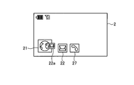
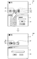
- FIG. 13 is a diagram illustrating an example of control when a function is activated in a state where other functions are not activated.
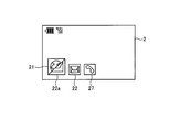
- FIG. 14A is a diagram illustrating an example of control when a function is activated in a state where one function is activated.
- FIG. 14B and FIG. 14C are diagrams illustrating another example of control when a function is activated in a state where one function is activated.
- FIG. 15 is a diagram illustrating an example of control when a function is activated in a state where two functions are activated.
- FIG. 16 is a diagram illustrating an example of control in the case where the suspended function is resumed.
- FIG. 17 is a diagram illustrating another example of the control in the case where the suspended function is resumed.
- FIG. 18 is a diagram illustrating an example of control in a case where the function being executed is terminated.
- the touch panel 2 is normally used as a display unit for displaying an object for activating a function of the mobile phone terminal 101, and the touch panel 3 is usually a display for displaying a screen provided by the activated function. It shall be used as a part.
- a standby screen in which the icon 21, the icon 22, and the icon 27 are arranged is displayed on the touch panel 2.
- the touch panel 3 displays a standby screen on which no icons are arranged.
- the icon 21 is an object used to activate the WEB browsing function.
- the icon 22 is an object used to activate the electronic mail function.
- the icon 27 is an object used to activate the call function.
- an icon 21 or the like made of a pictograph is displayed as an object for activating a function of the mobile phone terminal 101.
- a menu item, a button, or the like is displayed as an object for activating a function. It may be displayed.
- the tap operation may be a single tap operation, a double tap operation, or a long tap operation.
- the mobile phone terminal 101 activates a function corresponding to the tapped object, and a screen corresponding to the function. Is displayed on the touch panel 3.
- the cellular phone terminal 101 activates the e-mail function corresponding to the icon 22 and displays the mail creation screen 31 provided by the e-mail function on the touch panel 3 in step S ⁇ b> 72.
- step S73 shown in FIG. 14A as in step S72 of FIG. 13, a standby screen on which the icons 21, 22 and 27 are arranged is displayed on the touch panel 2, and a mail creation screen is displayed on the touch panel 3. 31 is displayed. That is, in step S73, only the electronic mail function corresponding to the icon 22 is executed. Here, it is assumed that the user performs a tap operation on the icon 21.
- the mobile phone terminal 101 interrupts the function being executed, and the symbol corresponding to the interrupted function is tapped. Display in or near the object display area. Furthermore, the mobile phone terminal 101 activates a function corresponding to the tapped object, and displays a screen corresponding to the function on the touch panel 3.
- the symbol here is displayed to indicate that there is another function interrupted to activate the function being executed.
- the symbol may be, for example, a simple graphic such as a circle or a rectangle, a character indicating the name of another function that has been interrupted, or another function that has been interrupted as in the example of FIG. 14A.
- the icon corresponding to may be reduced. If a symbol indicating a name of another interrupted function or an icon corresponding to the interrupted function is reduced as a symbol, the user can easily identify the interrupted function.
- Displaying the symbol in or near the object display area includes displaying the symbol so as to partially overlap the object display area.
- displaying a symbol in or near the object display area may be expressed as adding a symbol to the object.
- the cellular phone terminal 101 interrupts the e-mail function and adds a symbol 22a corresponding to the e-mail function to the icon 21 in step S74. Then, the mobile phone terminal 101 activates the WEB browsing function corresponding to the icon 21 and displays the browser screen 32 provided by the WEB browsing function on the touch panel 3.
- the icon 21 to which the symbol 22a corresponding to the interrupted function is added may be enlarged and displayed. By controlling in this way, it becomes easier for the user to grasp which function is being interrupted and to identify the added symbol.
- the icon 21 and the symbol 22a may be integrated and displayed.
- step S75 shown in FIG. 15 as in step S74 of FIG. 14A, a standby screen in which the icons 21, 22 and 27 are arranged is displayed on the touch panel 2, and the browser screen 32 is displayed on the touch panel 3. Is displayed.
- the icon 21 is added with a symbol 22a corresponding to the electronic mail function. That is, in step S75, the WEB browsing function is being executed and the electronic mail function is being interrupted. Here, it is assumed that the user performs a tap operation on the icon 27.
- the mobile phone terminal 101 interrupts the function being executed, and the symbol corresponding to the interrupted function is tapped. Append to object. At this time, the cellular phone terminal 101 also adds a symbol corresponding to the already interrupted function to the tapped object. Furthermore, the mobile phone terminal 101 activates a function corresponding to the tapped object, and displays a screen corresponding to the function on the touch panel 3.
- the cellular phone terminal 101 interrupts the WEB browsing function and adds a symbol 21a corresponding to the WEB browsing function and a symbol 22a corresponding to the e-mail function to the icon 27 in step S76. . Then, the cellular phone terminal 101 activates a call function corresponding to the icon 27 and displays a call screen 33 provided by the call function on the touch panel 3.
- the symbols corresponding to the interrupted functions are arranged in ascending order of elapsed time since the interruption. In this way, since the symbols are arranged in the order of short elapsed time since the interruption, the user can grasp in what order the functions are interrupted. Furthermore, as will be described later, since the function with the shortest elapsed time since the interruption is the target of resumption, the user can determine which function is resumed when an operation for resuming the suspended function is performed. I can grasp it.
- step S77 shown in FIG. 16 a standby screen in which the icon 21, the icon 22, and the icon 27 are arranged is displayed on the touch panel 2, and the call screen 33 is displayed on the touch panel 3, as in step S76 of FIG. Is displayed.
- the icon 27 is added with a symbol 21a corresponding to the WEB browsing function and a symbol 22a corresponding to the electronic mail function. That is, in step S77, the call function is being executed, and the WEB browsing function and the e-mail function are being interrupted. Here, it is assumed that the user performs a tap operation on the icon 27.
- the mobile phone terminal 101 interrupts the function being executed, The function with the shortest elapsed time after being interrupted at is resumed. At this time, the mobile phone terminal 101 adds a symbol corresponding to the suspended function to the object corresponding to the resumed function. In addition, the mobile phone terminal 101 displays a screen corresponding to the resumed function on the touch panel 3.
- the mobile phone terminal 101 interrupts the call function in step S78, restarts the WEB browsing function having the shortest elapsed time since the interruption, and the browser screen 32 provided by the WEB browsing function. Is displayed on the touch panel 3. Then, the cellular phone terminal 101 adds a symbol 23 a corresponding to the interrupted call function and a symbol 22 a corresponding to the interrupted electronic mail function to the icon 21.
- the icon 27 is added with a symbol 21a corresponding to the WEB browsing function and a symbol 22a corresponding to the electronic mail function. That is, in step S79, the call function is being executed, and the WEB browsing function and the e-mail function are being interrupted.
- the pinch operation refers to an operation in which a plurality of fingers are brought into contact with the touch panel and then the distance between the contact positions of the fingers is changed by moving the fingers while maintaining contact with the touch panel.
- the mobile phone terminal 101 interrupts the function being executed, The function with the shortest elapsed time after being interrupted at is resumed. At this time, the mobile phone terminal 101 adds a symbol corresponding to the suspended function to the object corresponding to the resumed function. Further, the mobile phone terminal 101 displays a screen corresponding to the resumed function on the touch panel 2 instead of the touch panel 3.
- the mobile phone terminal 101 interrupts the call function, resumes the WEB browsing function having the shortest elapsed time since the interruption, and the browser screen 32 provided by the WEB browsing function in step S80. Is displayed on the touch panel 2. Then, the cellular phone terminal 101 adds a symbol 23 a corresponding to the interrupted call function and a symbol 22 a corresponding to the interrupted electronic mail function to the icon 21.
- the mobile phone terminal 101 allows the user to specify on which display unit the screen provided by the resumed function is to be displayed by a simple operation. It is configured to be able to.
- the function suspended by the operation on the object to which the symbol is added is resumed.
- the tap operation is performed on the icon corresponding to the suspended function.
- the function corresponding to the icon may be resumed.
- the suspended function When a tap operation or pinch operation is performed on an object with a symbol indicating that there is a suspended function, the suspended function is resumed, but other functions such as a sweep operation and a flick operation are resumed.
- the suspended function may be resumed by the operation. For example, when an operation for rotating an object to which a symbol indicating that there is a suspended function is performed, the suspended function may be resumed. In this case, depending on the amount of rotation of the object, the suspended functions may be resumed one by one in the order from the shortest elapsed time since the interruption.
- the suspended function may be resumed.
- the finger is released when the object is dragged from the touch panel 2 to the touch panel 3
- the screen provided by the resumed function is displayed while the screen provided by the function being executed is displayed on the touch panel 3. It may be displayed on the touch panel 2.
- the screen provided by the function being executed is displayed on the touch panel 2
- the screen provided by the resumed function is displayed on the touch panel 3. It may be displayed. The relationship between the drag direction and the display position of the screen may be reversed.
- step S81 shown in FIG. 18 a standby screen in which the icon 21, icon 22, and icon 27 are arranged is displayed on the touch panel 2, and the call screen 33 is displayed on the touch panel 3, as in step S76 of FIG. Is displayed.
- the icon 27 is added with a symbol 21a corresponding to the WEB browsing function and a symbol 22a corresponding to the electronic mail function. That is, in step S81, the call function is being executed, and the WEB browsing function and the e-mail function are being interrupted. Here, it is assumed that the user has performed a predetermined operation for terminating the call function.
- the mobile phone terminal 101 ends the function being executed, and the elapsed time since the interruption is the longest among the functions being interrupted. Resume short functions. At this time, if there is another suspended function, the mobile phone terminal 101 adds a symbol corresponding to the suspended function to the object corresponding to the resumed function. Furthermore, the mobile phone terminal 101 displays a screen corresponding to the resumed function on the touch panel 3.
- the mobile phone terminal 101 terminates the call function, restarts the WEB browsing function having the shortest elapsed time since being interrupted, and returns to the browser screen 32 provided by the WEB browsing function in step S82. Is displayed on the touch panel 3.
- the mobile phone terminal 101 adds a symbol 22a corresponding to the suspended email function to the icon 21.
- FIG. 19 is a block diagram showing a functional configuration of the mobile phone terminal 101.
- the mobile phone terminal 101 includes a touch panel 2, a touch panel 3, a form detection unit 4, a power supply unit 5, a communication unit 6, a speaker 7, a microphone 8, a storage unit 9, and a control. Part 10 and RAM 11.
- the storage unit 9 is a mail program 9A for realizing an e-mail function, a browser program 9B for realizing a WEB browsing function, a call program 9E for realizing a call function, and a screen control as described above.
- Control program 9F and execution status data 9G in which information related to the execution status of the function is stored.
- the storage unit 9 stores other programs and data such as an operating system program for realizing the basic functions of the mobile phone terminal 101 and address book data in which names, telephone numbers, mail addresses, etc. are registered. Is done.
- the execution status data 9G will be described with reference to FIG.
- FIG. 20 is a diagram illustrating an example of the execution status data 9G.
- the execution status data 9G has items such as a hierarchy number and a program name, and data is stored for each activated function.
- the execution status data 9G is provided for each display unit, and the execution status data 9G illustrated in FIG. 20 is the execution status data 9G corresponding to the touch panel 3 at the time of step S76 illustrated in FIG.
- a value indicating the function execution order is stored in the hierarchy number item. Specifically, when a certain function is being executed, “0” is stored in the item of the layer number of the data corresponding to the function. In addition, when a certain function is suspended, the value of “1” or more assigned to the item of the hierarchical number of the data corresponding to the function by increasing the value one by one in the shortest elapsed time since the interruption. Is stored.
- the name of a program for realizing the function is stored in the program name item.
- the execution status data 9G is updated by the control unit 10 every time a function is activated, interrupted, resumed, terminated, or the like.
- the control unit 10 comprehensively controls the operation of the mobile phone terminal 101. For example, by executing the control program 9F, the control unit 10 realizes a function of changing the display mode of an object such as an icon in accordance with the execution or interruption of the function as described above.
- the processing procedure shown in FIG. 21 is executed each time the touch panel 2 detects contact with an object such as an icon corresponding to an executable function when the mobile phone terminal 101 is in the second form.
- FIG. 21 is a flowchart showing the operation of the control unit 10 when contact with an icon corresponding to an executable function is detected.
- the control unit 10 determines whether a symbol is added to the icon with contact detected as step S302.
- the fact that a symbol is added to an icon means that, for example, the function data corresponding to the icon is stored in the execution status data 9G with “0” set in the item of the hierarchy number and the execution status data 9G. Can be determined from the fact that data of other functions are stored in
- Step S302 When the symbol is not added to the icon in which the contact is detected (No at Step S302), the control unit 10 determines whether the contact is a tap operation as Step S303. Here, if the contact is not due to a tap operation (step S303, No), the control unit 10 does not perform any particular processing.
- step S303 If the contact is by a tap operation (step S303, Yes), the control unit 10 determines whether there is a function being executed as step S304. Whether there is a function being executed is determined from, for example, whether data is stored in the execution status data 9G. When there is no function being executed (No at Step S304), the control unit 10 activates a function corresponding to the tapped icon and displays a screen provided by the function on the touch panel 3 at Step S308.
- step S304 When there is a function being executed (Yes in step S304), the control unit 10 deletes the symbol added to the icon of the function being executed as step S305, and interrupts the function being executed as step S306. .
- step S307 the control unit 10 adds a suspended function symbol to the tapped icon. Then, the control part 10 starts the function corresponding to the tapped icon as step S308, and displays the screen which the function provides on the touch panel 3. FIG. The order in which steps S305 to S308 are executed does not have to be this.
- step S302 when the symbol is added to the icon in which the contact is detected (step S302, Yes), the control unit 10 determines whether the contact is a tap operation as step S309. When the contact is due to a tap operation (step S309, Yes), the control unit 10 sets a function whose execution has been interrupted last as a restart target in step S310.
- the function whose execution was interrupted last time can be specified by searching the execution status data 9G for data in which “1” is set in the item of the hierarchy number, for example.
- step S311 the control unit 10 erases the symbol added to the icon of the function being executed, and interrupts the function being executed in step S312.
- step S313 the control unit 10 adds a suspended function symbol to the icon of the function to be resumed.
- the symbols are arranged in the order from the shortest elapsed time since the interruption based on the value of the item of the hierarchy number of the execution status data 9G.
- step S314 the control unit 10 resumes the function to be resumed and causes the touch panel 3 to display a screen provided by the function.
- the order in which steps S311 to S314 are executed does not have to be this.
- step S309, No the control unit 10 determines whether the contact is due to a tap operation as step S315. When the contact is not due to a pinch operation (step S315, No), the control unit 10 does not perform any particular processing.
- step S315, Yes the control unit 10 sets the function whose execution was interrupted last as the target of resumption as step S316. Subsequently, in step S317, the control unit 10 deletes the symbol of the function to be resumed from the icon of the function being executed. In step S318, the control unit 10 resumes the function to be resumed, and displays the screen provided by the function on the touch panel 2 instead of the touch panel 3. The order in which step S317 and step S318 are performed does not have to be this.
- the screen provided by the function to be resumed is displayed on the touch panel 2.
- it may be executed with another operation such as a double tap operation as a trigger.
- the present invention is applied to an electronic device having a touch panel.
- an electronic device configured to operate an object such as an icon using a mouse, a touch pad, a trackball, or the like.
- the technology according to the present embodiment can be applied.
- the tap operation in the above description may be replaced with a click operation
- the pinch operation may be replaced with a double click operation.
- FIG. 22 is a diagram illustrating an example of control when a function is activated in a state where other functions are not activated.
- FIG. 23 is a diagram illustrating an example of control when a function is activated in a state where one function is activated.
- the touch panel 20 is divided into two display areas, a display area 20A and a display area 20B.
- the display area 20A is used to display a function screen provided by various functions.
- the display area 20B is used for arranging objects such as icons for activating various functions.
- An icon 21, an icon 22, and an icon 27 are arranged in the display area 20B. No screen of any function is displayed in the display area 20A.
- step S84 an e-mail function corresponding to the icon 22 is activated, and a mail creation screen 31 provided by the e-mail function is displayed in the display area 20A.
- step S85 shown in FIG. 23 similarly to step S84 in FIG. 22, the icon 21, the icon 22, and the icon 27 are arranged in the display area 20B, and the mail creation screen 31 is displayed in the display area 20A. Has been. That is, in step S85, only the electronic mail function corresponding to the icon 22 is activated.
- the user performs a tap operation on the icon 21.
- the function being executed is interrupted, and a symbol corresponding to the interrupted function is added to the tapped object.
- a function corresponding to the tapped object is activated, and a screen corresponding to the function is displayed in the display area 20A.
- step S86 the e-mail function is interrupted, and a symbol 22a corresponding to the e-mail function is added to the icon 21. Then, the WEB browsing function corresponding to the icon 21 is activated, and the browser screen 32 provided by the WEB browsing function is displayed in the display area 20A.
- control program 9C and the control program 9F may be divided into a plurality of modules or may be integrated with other programs.
- the control program 9C and the control program 9F may be stored in a portable non-transitory storage medium such as a CD, a DVD, a Blu-ray, a memory card, and may be read by the mobile phone terminal 1 or the mobile phone terminal 101. .
- the mobile phone terminals 1 and 101 change from the first form to the second form by sliding the first case 1A relative to the second case 1B.
- the change from the first form to the second form may be realized by other than the sliding operation.
- the mobile phone terminal 1 and the mobile phone terminal 101 may be a foldable terminal in which a first housing 1A and a second housing 1B are coupled by a biaxial rotary hinge.
- a change in form is realized by relatively rotating the first casing 1A and the second casing 1B with the two axes of the hinge as the rotation axes.
Landscapes
- Engineering & Computer Science (AREA)
- General Engineering & Computer Science (AREA)
- Theoretical Computer Science (AREA)
- Human Computer Interaction (AREA)
- Physics & Mathematics (AREA)
- General Physics & Mathematics (AREA)
- Environmental & Geological Engineering (AREA)
- Computer Networks & Wireless Communication (AREA)
- Signal Processing (AREA)
- Telephone Function (AREA)
- User Interface Of Digital Computer (AREA)
Abstract
A mobile phone terminal (electronic device) (1) is provided with: a first chassis having a touch panel (2); a second chassis having a touch panel (3); and a control unit (10) which controls the display of information on the touch panels (2, 3). If a change of the electronic device (1) takes place, from a first form in which the touch panel (2) is uncovered and exposed externally while the touch panel (3) is covered and hidden by the first chassis, to a second form in which both the touch panels (2, 3) are uncovered and exposed externally, then the control unit (10) activates a function corresponding to an object selected from objects displayed on the touch panel (2), and displays on the touch panel (3) a screen display corresponding to the function.
Description
本発明は、電子機器、制御方法および制御プログラムに関する。
The present invention relates to an electronic device, a control method, and a control program.
近年、直感的な操作を可能にするとともに、キーボードのように物理的に大きな面積を必要とするデバイスを具備しない小型の電子機器を実現するために、タッチパネルが広く利用されるようになっている。また、特許文献1では、2つのタッチパネルを有し、2つのタッチパネルが露出する開状態と1つのタッチパネルのみが露出する閉状態のいずれかに変位し、開状態にて受信した発信元へ、閉状態への変位を契機として発信をする電話端末が提案されている。
In recent years, touch panels have been widely used to realize small electronic devices that can be operated intuitively and do not include devices that require a physically large area such as a keyboard. . Further, in Patent Document 1, there are two touch panels, and the touch panel is displaced to either an open state in which two touch panels are exposed or a closed state in which only one touch panel is exposed. There has been proposed a telephone terminal that makes a call in response to a displacement to a state.
上記の特許文献1に記載されている技術は、通話に関する操作について利用者の利便性を向上させることができるものの、電子機器が有するその他の機能に関する操作については特に考慮されていない。近年の電子機器は多種多様な機能を備えるようになっており、通話以外の機能の操作についても利用者の利便性を向上させることが要望されている。
The technique described in Patent Document 1 described above can improve the convenience of the user for operations related to calls, but does not particularly take into account operations related to other functions of electronic devices. In recent years, electronic devices are provided with a wide variety of functions, and there is a demand for improving the convenience of users for the operation of functions other than calls.
本発明は、上記に鑑みてなされたものであって、利用者の利便性を向上させることができる電子機器、制御方法および制御プログラムを提供することを目的とする。
The present invention has been made in view of the above, and an object of the present invention is to provide an electronic device, a control method, and a control program that can improve user convenience.
本発明に係る電子機器は、1つの態様において、第1の表示部を有する第1の筐体と、第2の表示部を有する第2の筐体と、第1の表示部が外部へ露出し前記第2の表示部が前記第1の筐体によって覆い隠される第1の形態と、前記第1の表示部および前記第2の表示部が外部へ露出する第2の形態とを検出する検出部と、当該電子機器が前記第1の形態から前記第2の形態へ変化したことが前記検出部によって検出された場合に、前記第1の表示部に表示されているオブジェクトのうち、選択されているオブジェクトに対応する機能を起動させ、当該機能に対応する画面を前記第2の表示部に表示させる制御部と、を備える。
In one aspect, an electronic device according to the present invention has a first housing having a first display portion, a second housing having a second display portion, and the first display portion exposed to the outside. And detecting the first form in which the second display unit is covered by the first housing and the second form in which the first display unit and the second display unit are exposed to the outside. When the detection unit and the detection unit detect that the electronic device has changed from the first form to the second form, a selection is made from among the objects displayed on the first display unit. A control unit that activates a function corresponding to the object being displayed and displays a screen corresponding to the function on the second display unit.
本発明に係る制御方法は、1つの態様において、第1の表示部を有する第1の筐体と、第2の表示部を有する第2の筐体と、検出部とを備える電子機器の制御方法であって、検出部によって、当該電子機器が、第1の表示部が外部へ露出し前記第2の表示部が前記第1の筐体によって覆い隠される第1の形態から、前記第1の表示部および前記第2の表示部が外部へ露出する第2の形態へ変化したことを検出するステップと、当該電子機器が前記第2の形態へ変化したことが検出された場合に、前記第1の表示部に表示されているオブジェクトのうち、選択されているオブジェクトに対応する機能を起動させ、当該機能に対応する画面を前記第2の表示部に表示させるステップとを含む。
In one aspect, a control method according to the present invention controls an electronic device including a first casing having a first display section, a second casing having a second display section, and a detection section. In the method, the electronic device may be configured such that the first display unit is exposed to the outside and the second display unit is covered with the first casing by the detection unit. Detecting that the display unit and the second display unit have changed to the second form exposed to the outside, and when detecting that the electronic device has changed to the second form, Starting a function corresponding to the selected object among the objects displayed on the first display unit, and displaying a screen corresponding to the function on the second display unit.
本発明に係る制御プログラムは、1つの態様において、第1の表示部を有する第1の筐体と、第2の表示部を有する第2の筐体と、検出部とを備える電子機器に、検出部によって、当該電子機器が、第1の表示部が外部へ露出し前記第2の表示部が前記第1の筐体によって覆い隠される第1の形態から、前記第1の表示部および前記第2の表示部が外部へ露出する第2の形態へ変化したことを検出するステップと、当該電子機器が前記第2の形態へ変化したことが検出された場合に、前記第1の表示部に表示されているオブジェクトのうち、選択されているオブジェクトに対応する機能を起動させ、当該機能に対応する画面を前記第2の表示部に表示させるステップとを実行させる。
In one aspect, a control program according to the present invention is provided in an electronic device including a first casing having a first display section, a second casing having a second display section, and a detection section. From the first form in which the electronic device has the first display unit exposed to the outside and the second display unit is covered with the first housing by the detection unit, the first display unit and the first display unit The step of detecting that the second display unit has changed to the second form exposed to the outside, and the first display unit when it is detected that the electronic device has changed to the second form A function corresponding to the selected object among the objects displayed on the screen is activated, and a step of displaying a screen corresponding to the function on the second display unit is executed.
本発明に係る電子機器、制御方法および制御プログラムは、利用者の利便性を向上させることができる。
The electronic device, the control method, and the control program according to the present invention can improve user convenience.
以下、本発明につき図面を参照しつつ詳細に説明する。なお、以下の説明により本発明が限定されるものではない。また、以下の説明における構成要素には、当業者が容易に想定できるもの、実質的に同一のもの、いわゆる均等の範囲のものが含まれる。以下においては、電子機器として携帯電話端末を例として説明するが、本発明の適用対象は携帯電話端末に限定されるものではなく、タッチパネルを備える各種装置、例えば、PHS(Personal Handyphone System)、PDA、ポータブルナビゲーション装置、パーソナルコンピュータ、メディアプレイヤ、電子書籍リーダ、ゲーム機等に対しても本発明は適用できる。
Hereinafter, the present invention will be described in detail with reference to the drawings. The present invention is not limited to the following description. In addition, constituent elements in the following description include those that can be easily assumed by those skilled in the art, those that are substantially the same, and those in a so-called equivalent range. In the following, a mobile phone terminal will be described as an example of an electronic device. However, the application target of the present invention is not limited to a mobile phone terminal, and various devices including a touch panel, such as PHS (Personal Handyphone System), PDA The present invention can also be applied to portable navigation devices, personal computers, media players, electronic book readers, game machines, and the like.
(第1実施形態)
まず、図1および図2を参照しながら、本実施形態に係る携帯電話端末1の外観について説明する。図1は、第1の形態にある携帯電話端末1の斜視図であり、図2は、第2の形態にある携帯電話端末1の斜視図である。携帯電話端末1は、第1の筐体1Aと、第2の筐体1Bとを有する。第1の筐体1Aは、第2の筐体1Bに対して矢印Aの方向に相対的にスライド可能に構成されている。 (First embodiment)
First, the external appearance of themobile phone terminal 1 according to the present embodiment will be described with reference to FIGS. 1 and 2. FIG. 1 is a perspective view of the mobile phone terminal 1 in the first form, and FIG. 2 is a perspective view of the mobile phone terminal 1 in the second form. The mobile phone terminal 1 has a first housing 1A and a second housing 1B. The first housing 1A is configured to be relatively slidable in the direction of arrow A with respect to the second housing 1B.
まず、図1および図2を参照しながら、本実施形態に係る携帯電話端末1の外観について説明する。図1は、第1の形態にある携帯電話端末1の斜視図であり、図2は、第2の形態にある携帯電話端末1の斜視図である。携帯電話端末1は、第1の筐体1Aと、第2の筐体1Bとを有する。第1の筐体1Aは、第2の筐体1Bに対して矢印Aの方向に相対的にスライド可能に構成されている。 (First embodiment)
First, the external appearance of the
第1の筐体1Aは、第2の筐体1Bと対向する面と反対側の面にタッチパネル2を有する。第2の筐体1Bは、第1の筐体1Aと対向する面にタッチパネル3を有する。タッチパネル2およびタッチパネル3は、文字、図形、画像等を表示するとともに、利用者が指やスタイラス等(以下、単に「指」と言う)を用いて当該タッチパネルに対して行う各種操作を検出する。タッチパネル3は、第1の筐体1Aと第2の筐体1Bとが重なり合う第1の形態では第1の筐体1Aによって覆い隠され、第1の筐体1Aが矢印Aの方向にスライドした第2の形態では外部に露出する。
The first housing 1A has a touch panel 2 on the surface opposite to the surface facing the second housing 1B. The second housing 1B has a touch panel 3 on the surface facing the first housing 1A. The touch panel 2 and the touch panel 3 display characters, figures, images, and the like, and detect various operations performed on the touch panel by a user using a finger, a stylus, or the like (hereinafter simply referred to as “finger”). The touch panel 3 is covered and hidden by the first casing 1A in the first form in which the first casing 1A and the second casing 1B overlap, and the first casing 1A slides in the direction of the arrow A. In the second form, it is exposed to the outside.
第1の形態は、利用者が携帯電話端末1を持ち運ぶのに適した形態であり、この形態でも利用者は、タッチパネル2に表示される情報を参照したり、タッチパネル2を指で操作して情報を入力したりすることができる。第2の形態は、利用者が携帯電話端末1を利用するのに適した形態であり、利用者は、タッチパネル2とタッチパネル3とを併用して、より多くの情報を参照することができる。
The first form is a form suitable for the user to carry the mobile phone terminal 1. In this form as well, the user refers to information displayed on the touch panel 2 or operates the touch panel 2 with a finger. You can enter information. The second form is a form suitable for the user to use the mobile phone terminal 1, and the user can refer to more information by using the touch panel 2 and the touch panel 3 together.
以下の説明では、常時外部に露出しているタッチパネル2を第1の表示部と呼び、第1の形態では第1の筐体1Aによって覆い隠され第2の形態では外部に露出するタッチパネル3を第2の表示部と呼ぶことがある。
In the following description, the touch panel 2 that is always exposed to the outside is referred to as a first display unit. In the first form, the touch panel 3 that is covered with the first casing 1A and exposed to the outside in the second form. Sometimes referred to as a second display unit.
次に、図3から図5を参照しながら、携帯電話端末1が形態の変化と連動して機能を制御する方式について説明する。図3は、形態の変化と連動して機能を起動させる例を示す図である。図4は、形態の変化と連動して機能を中断させる例を示す図である。図5は、形態の変化と連動して機能を再開させる例を示す図である。
Next, a method in which the mobile phone terminal 1 controls functions in conjunction with a change in form will be described with reference to FIGS. FIG. 3 is a diagram illustrating an example in which a function is activated in conjunction with a change in form. FIG. 4 is a diagram illustrating an example in which a function is interrupted in conjunction with a change in form. FIG. 5 is a diagram illustrating an example of resuming a function in conjunction with a change in form.
図3に示すステップS11では、携帯電話端末1は第1の形態にあり、第1の表示部にはアイコン21とアイコン22とが配置された待受画面が表示されている。アイコン21は、WEBブラウジング機能を新規に起動させるために用いられるオブジェクトであり、アイコン22は、電子メール機能を新規に起動させるために用いられるオブジェクトである。
In step S11 shown in FIG. 3, the mobile phone terminal 1 is in the first form, and a standby screen in which icons 21 and 22 are arranged is displayed on the first display unit. The icon 21 is an object used for newly starting a WEB browsing function, and the icon 22 is an object used for newly starting an electronic mail function.
待受画面とは、電話の発着信を待ち受けている状態の画面、または、アプリケーションプログラムの起動を待ち受けている状態の画面である。換言すると、待受画面は、携帯電話端末1が提供する各種機能を利用するための画面(以下、「機能画面」とも言う)へ画面が変わる前の画面である。待受画面は、例えば、デスクトップ画面、ホーム画面、または、壁紙と呼ばれることもある。図3に示した例では、無地の画面が待受画面として表示されているが、画像データやアニメーションデータを待受画面として表示してもよい。待受画面の一部として、カレンダや時計のように動的に変化する部分が含まれていてもよい。
The standby screen is a screen in a state waiting for incoming / outgoing calls, or a screen in a state waiting for starting an application program. In other words, the standby screen is a screen before the screen is changed to a screen for using various functions provided by the mobile phone terminal 1 (hereinafter also referred to as “function screen”). The standby screen may be called a desktop screen, a home screen, or wallpaper, for example. In the example shown in FIG. 3, a plain screen is displayed as the standby screen, but image data and animation data may be displayed as the standby screen. As a part of the standby screen, a dynamically changing part such as a calendar or a clock may be included.
ステップS12として、利用者がアイコン22に対してシングルタップ操作を行うと、携帯電話端末1は、アイコン22を選択状態にする。携帯電話端末1は、選択状態となったアイコン22を、例えば、明度を低下させることによって、他のアイコンと識別可能にする。シングルタップ操作とは、アイコン等を軽くたたくように、指をタッチパネルに接触させた後にすぐ離す動作を一度だけ行う操作をいう。
In step S12, when the user performs a single tap operation on the icon 22, the mobile phone terminal 1 places the icon 22 in a selected state. The mobile phone terminal 1 makes the selected icon 22 distinguishable from other icons by, for example, reducing the brightness. The single tap operation is an operation in which a finger is touched on the touch panel and then immediately released once so as to tap an icon or the like.
そして、アイコン22が選択状態にあるときに、ステップS13として、利用者が携帯電話端末1を第1の形態から第2の形態へ変化させたとする。この場合、携帯電話端末1は、選択状態にあるアイコン22に対応する電子メール機能を第2の表示部で起動させる。ここで、「電子メール機能を第2の表示部で起動させる」とは、電子メール機能を起動させ、電子メール機能が提供する画面を第2の表示部に表示させることを意味する。電子メール機能が提供する画面は、例えば、メール作成画面31である。
When the icon 22 is in the selected state, it is assumed that the user changes the mobile phone terminal 1 from the first form to the second form in step S13. In this case, the cellular phone terminal 1 activates the e-mail function corresponding to the icon 22 in the selected state on the second display unit. Here, “starting the electronic mail function on the second display unit” means starting the electronic mail function and displaying a screen provided by the electronic mail function on the second display unit. A screen provided by the electronic mail function is, for example, a mail creation screen 31.
このように、携帯電話端末1は、第1の形態から第2の形態へ変化する際に、第1の表示部において選択状態となっているアイコンがあれば、そのアイコンに対応する機能を第2の表示部で起動させる。このため、利用者は、携帯電話端末1を第1の形態にして持ち歩いている最中に第2の表示部で何らかの機能を起動させたくなった場合には、その機能に対応するアイコンを第1の表示部で選択状態にする。このようにすることにより、利用者は、携帯電話端末1を第2の形態へ変形させて第2の表示部を露出させる動作と連動して、希望する機能を第2の表示部で起動させることができる。
As described above, when the mobile phone terminal 1 changes from the first form to the second form, if there is an icon selected in the first display unit, the mobile phone terminal 1 has a function corresponding to the icon. 2 is activated on the display unit. For this reason, if the user wants to activate any function on the second display unit while carrying the mobile phone terminal 1 in the first form, the user can select an icon corresponding to the function. 1 is selected. In this way, the user activates the desired function on the second display unit in conjunction with the operation of transforming the mobile phone terminal 1 into the second form and exposing the second display unit. be able to.
そして、図4のステップS21のように第2の表示部で電子メール機能が起動されている状態で、利用者が携帯電話端末1を第1の形態へ変化させたものとする。この場合、携帯電話端末1は、ステップS22として、第2の表示部で起動していた電子メール機能を中断させ、電子メール機能が中断中であることを示すアイコン23を第1の表示部に表示させる。
Then, it is assumed that the user changes the mobile phone terminal 1 to the first form while the electronic mail function is activated on the second display unit as in step S21 of FIG. In this case, in step S22, the cellular phone terminal 1 interrupts the e-mail function activated on the second display unit, and displays an icon 23 indicating that the e-mail function is suspended on the first display unit. Display.
アイコン23は、電子メール機能を起動させるためのアイコン22と同様の外観を有し、対応する機能が中断中であることを識別できるように「!(イクスクラメーションマーク)」が付加されている。「!」を付加するのは一例であり、中断中の機能を示すアイコンは、機能を新規に起動するためのアイコンと何らかのやり方で区別できればよい。例えば、中断直前の第2の表示部のサムネイル画像をアイコン23として表示してもよい。
The icon 23 has the same appearance as the icon 22 for starting the e-mail function, and “! (Exclamation mark)” is added so that it can be identified that the corresponding function is suspended. . The addition of “!” Is an example, and an icon indicating a suspended function may be distinguished from an icon for newly starting a function in some way. For example, the thumbnail image of the second display unit immediately before the interruption may be displayed as the icon 23.
このように、利用者が携帯電話端末1を第2の形態にして第2の表示部で何らかの機能を利用している最中に何らかの理由で利用を中断しなければならなくなった場合、利用者は、携帯電話端末1を第1の形態へ戻すことによって機能を中断させることができる。すなわち、利用者は、携帯電話端末1を持ち運びが容易な第1の形態へ戻すことによって、第2の表示部で起動している機能を中断させ、そのまま携帯電話端末1を手に持って持ち運んだり、かばんにしまったりすることができる。
As described above, when the user has to suspend the use for some reason while using the mobile phone terminal 1 in the second form and using any function in the second display unit, Can interrupt the function by returning the mobile phone terminal 1 to the first form. That is, the user interrupts the function activated in the second display unit by returning the mobile phone terminal 1 to the first form that is easy to carry, and carries the mobile phone terminal 1 as it is. Or you can put it in your bag.
そして、図5のステップS31のように、中断されている機能に対応するアイコン23が第1の表示部に表示されている状態で、利用者が、中断されている機能を再開したくなったものとする。この場合、利用者は、ステップS32として、アイコン23に対してシングルタップ操作を行う。携帯電話端末1は、アイコン23に対してシングルタップ操作が行われると、アイコン23を選択状態にする。
Then, as shown in step S31 of FIG. 5, the user wants to resume the suspended function while the icon 23 corresponding to the suspended function is displayed on the first display unit. Shall. In this case, the user performs a single tap operation on the icon 23 as step S32. When a single tap operation is performed on the icon 23, the mobile phone terminal 1 places the icon 23 in a selected state.
そして、アイコン23が選択状態にあるときに利用者がステップS33として携帯電話端末1を第1の形態から第2の形態へ変化させると、携帯電話端末1は、アイコン23に対応する電子メール機能を第2の表示部で再開させる。また、携帯電話端末1は、電子メール機能を再開させたことにともなって、アイコン23を第1の表示部から削除する。
When the user changes the mobile phone terminal 1 from the first form to the second form in step S33 when the icon 23 is in the selected state, the mobile phone terminal 1 has an e-mail function corresponding to the icon 23. Is resumed on the second display section. In addition, the cellular phone terminal 1 deletes the icon 23 from the first display unit when the electronic mail function is resumed.
このように、携帯電話端末1は、第1の形態から第2の形態へ変化する際に、中断中の機能に対応するアイコンが第1の表示部において選択状態となっていれば、そのアイコンに対応する機能を第2の表示部で再開させる。このため、利用者は、第2の表示部で起動していた機能を再開させたくなった場合には、その機能に対応するアイコンを第1の表示部で選択状態にする。このようにすることにより、利用者は、携帯電話端末1を第2の形態へ変形させて第2の表示部を露出させる動作と連動して、希望する機能を第2の表示部で再開させることができる。
As described above, when the mobile phone terminal 1 changes from the first form to the second form, if the icon corresponding to the suspended function is in the selected state on the first display unit, the icon is displayed. The function corresponding to is restarted on the second display unit. For this reason, when the user wants to resume the function activated on the second display unit, the user selects the icon corresponding to the function on the first display unit. By doing so, the user resumes the desired function on the second display unit in conjunction with the operation of transforming the mobile phone terminal 1 into the second form and exposing the second display unit. be able to.
中断中の機能を第2の表示部ではなく、第1の表示部で再開させることもできる。図6を参照しながら、中断中の機能を第1の表示部で再開させる例について説明する。
It is also possible to resume the suspended function not on the second display unit but on the first display unit. With reference to FIG. 6, an example of resuming the suspended function on the first display unit will be described.
図6のステップS41のように、中断されている機能に対応するアイコン23が第1の表示部に表示されている状態で、利用者が、アイコン23に対してダブルタップ操作を行ったものとする。ダブルタップ操作とは、アイコン等を軽くたたくように、指をタッチパネルに接触させた後にすぐ離す動作を二度繰り返して行う操作をいう。
As shown in step S41 of FIG. 6, the user performs a double-tap operation on the icon 23 while the icon 23 corresponding to the interrupted function is displayed on the first display unit. To do. The double-tap operation is an operation in which a finger is brought into contact with the touch panel and then released immediately, so that the user taps an icon or the like twice.
この場合、携帯電話端末1は、ステップS42として、アイコン23に対応する電子メール機能を第2の表示部ではなく、第1の表示部で再開させる。このとき、携帯電話端末1は、電子メール機能を再開させたことにともなって、アイコン23を第1の表示部から削除する。その結果、利用者が電子メール機能を終了させた後、ステップS43に示すように、第1の表示部にはアイコン23が表示されない。
In this case, the cellular phone terminal 1 restarts the electronic mail function corresponding to the icon 23 in the first display unit instead of the second display unit in step S42. At this time, the cellular phone terminal 1 deletes the icon 23 from the first display unit as the electronic mail function is resumed. As a result, after the user ends the electronic mail function, the icon 23 is not displayed on the first display unit as shown in step S43.
利用者は、表示されているアイコンの詳細について、所定の操作を行うことで知ることができる。例えば、図7のステップS51のように、電子メール機能に対応するアイコン22が第1の表示部に表示されている状態で、利用者が、アイコン22に対してロングタップ操作を行ったものとする。ロングタップ操作とは、アイコン等を押し込むように、指をタッチパネルに所定の時間よりも長く接触させる操作をいう。
The user can know the details of the displayed icon by performing a predetermined operation. For example, as shown in step S51 of FIG. 7, the user performs a long tap operation on the icon 22 while the icon 22 corresponding to the e-mail function is displayed on the first display unit. To do. The long tap operation refers to an operation of bringing a finger into contact with the touch panel for a longer time than a predetermined time so as to push an icon or the like.
この場合、携帯電話端末1は、ステップS52として、アイコン22を選択状態にし、アイコン22に対応する機能が電子メール機能であることを示す吹き出し24等を第1の表示部に表示することで、アイコン22に対応する機能が何であるかを利用者に通知する。吹き出し24が表示されるタイミングは、タッチパネルへの指の接触が所定の時間よりも長くなったタイミングでもよい。この場合、指がタッチパネルから離れた場合に吹き出し24を消去してもよい。吹き出し24が表示されるタイミングは、指がタッチパネルから離れたタイミングでもよい。この場合、指がタッチパネルから離れてから他の所定の時間が経過した場合に吹き出し24を消去してもよい。
In this case, in step S52, the cellular phone terminal 1 sets the icon 22 in a selected state, and displays a balloon 24 or the like indicating that the function corresponding to the icon 22 is an e-mail function on the first display unit. The user is notified of what the function corresponding to the icon 22 is. The timing at which the balloon 24 is displayed may be a timing at which the touch of the finger on the touch panel becomes longer than a predetermined time. In this case, the balloon 24 may be deleted when the finger is separated from the touch panel. The timing at which the balloon 24 is displayed may be the timing at which the finger leaves the touch panel. In this case, the balloon 24 may be deleted when another predetermined time elapses after the finger leaves the touch panel.
同様に、図8のステップS61のように、中断中の電子メール機能に対応するアイコン23が第1の表示部に表示されている状態で、利用者が、アイコン23に対してロングタップ操作を行ったものとする。この場合、携帯電話端末1は、ステップS62として、アイコン23を選択状態にし、アイコン23に対応する機能が電子メール機能であり、メール作成を実行中に中断されたことを示す吹き出し25等を第1の表示部に表示することで、アイコン23に対応する機能が何であり、どのような処理を実行中に中断されたのかを利用者に通知する。
Similarly, as shown in step S61 of FIG. 8, the user performs a long tap operation on the icon 23 while the icon 23 corresponding to the suspended email function is displayed on the first display unit. Suppose you have gone. In this case, in step S62, the cellular phone terminal 1 sets the icon 23 to the selected state, and the function corresponding to the icon 23 is an e-mail function. By displaying on the display unit 1, the user is notified of what the function corresponding to the icon 23 is and what processing was interrupted during execution.
次に、図9を参照しながら、携帯電話端末1の機能的な構成について説明する。図9は、携帯電話端末1の機能的な構成を示すブロック図である。図9に示すように携帯電話端末1は、タッチパネル2と、タッチパネル3と、形態検出部4と、電源部5と、通信部6と、スピーカ7と、マイク8と、記憶部9と、制御部10と、RAM(Random Access Memory)11とを有する。タッチパネル2が第1の筐体1Aに設けられ、タッチパネル3が第2の筐体1Bに設けられることを除いて、各部位は、第1の筐体1Aと第2の筐体1Bのいずれに設けられてもよい。
Next, the functional configuration of the mobile phone terminal 1 will be described with reference to FIG. FIG. 9 is a block diagram showing a functional configuration of the mobile phone terminal 1. As shown in FIG. 9, the mobile phone terminal 1 includes a touch panel 2, a touch panel 3, a form detection unit 4, a power supply unit 5, a communication unit 6, a speaker 7, a microphone 8, a storage unit 9, and a control. Unit 10 and RAM (Random Access Memory) 11. Except that the touch panel 2 is provided in the first casing 1A and the touch panel 3 is provided in the second casing 1B, each part is in either the first casing 1A or the second casing 1B. It may be provided.
タッチパネル2は、表示部2Bと、表示部2Bに重畳されたタッチセンサ2Aとを有する。タッチパネル3は、表示部3Bと、表示部3Bに重畳されたタッチセンサ3Aとを有する。タッチセンサ2Aおよびタッチセンサ3Aは、指を用いて表面に対して行われた各種操作を、操作が行われた位置とともに検出する。タッチセンサ2Aおよびタッチセンサ3Aによって検出される操作には、シングルタップ操作、ダブルタップ操作、ロングタップ操作等が含まれる。表示部2Bおよび表示部3Bは、例えば、液晶ディスプレイ(LCD、Liquid Crystal Display)や、有機EL(Organic Electro-Luminescence)パネルなどで構成され、文字、図形、画像等を表示する。
The touch panel 2 includes a display unit 2B and a touch sensor 2A superimposed on the display unit 2B. The touch panel 3 includes a display unit 3B and a touch sensor 3A superimposed on the display unit 3B. The touch sensor 2 </ b> A and the touch sensor 3 </ b> A detect various operations performed on the surface using a finger together with the position where the operation is performed. The operations detected by the touch sensor 2A and the touch sensor 3A include a single tap operation, a double tap operation, a long tap operation, and the like. The display unit 2B and the display unit 3B are composed of, for example, a liquid crystal display (LCD) or an organic EL (Organic Electro-Luminescence) panel, and display characters, figures, images, and the like.
形態検出部4は、携帯電話端末1が第1の形態にあるのか、第2の形態にあるのかを検出する。形態検出部4は、例えば、第1の筐体1Aと第2の筐体1Bとが対向する面に設けられた機械的なスイッチによって携帯電話端末1の形態を検出する。
The form detection unit 4 detects whether the mobile phone terminal 1 is in the first form or the second form. The form detection unit 4 detects the form of the mobile phone terminal 1 using, for example, a mechanical switch provided on a surface where the first housing 1A and the second housing 1B face each other.
電源部5は、蓄電池または外部電源から得られる電力を、制御部10を含む携帯電話端末1の各機能部へ供給する。通信部6は、基地局によって割り当てられるチャネルを介し、基地局との間でCDMA方式などによる無線信号回線を確立し、基地局との間で電話通信及び情報通信を行う。スピーカ7は、電話通信における相手側の音声や着信音等を出力する。マイク8は、利用者等の音声を電気的な信号へ変換する。
The power supply unit 5 supplies power obtained from a storage battery or an external power supply to each functional unit of the mobile phone terminal 1 including the control unit 10. The communication unit 6 establishes a radio signal line by a CDMA system or the like with a base station via a channel assigned by the base station, and performs telephone communication and information communication with the base station. The speaker 7 outputs the other party's voice, ringtone, and the like in telephone communication. The microphone 8 converts the voice of the user or the like into an electrical signal.
記憶部9は、例えば、不揮発性メモリ(ROM、EPROM、メモリカード、ソリッドステートデバイス等)、磁気記憶装置、光記憶装置等の非一時的な記憶装置を少なくとも1つ含み、制御部10での処理に利用されるプログラムやデータを保存する。具体的には、記憶部9は、電子メール機能を実現するためのメールプログラム9A、WEBブラウジング機能を実現するためのブラウザプログラム9B、上述したような機能の制御を実現するための制御プログラム9C、および画面上に表示されるアイコンに関する情報が格納されたアイコンデータ9Dを記憶する。記憶部9には、その他に、携帯電話端末1の基本的な機能を実現するオペレーティングシステムプログラムや、氏名、電話番号、メールアドレス等が登録されたアドレス帳データ等の他のプログラムやデータも記憶される。
The storage unit 9 includes at least one non-transitory storage device such as a nonvolatile memory (ROM, EPROM, memory card, solid state device, etc.), magnetic storage device, optical storage device, etc. Save programs and data used for processing. Specifically, the storage unit 9 includes a mail program 9A for realizing an electronic mail function, a browser program 9B for realizing a WEB browsing function, a control program 9C for realizing control of the functions as described above, And the icon data 9D in which information related to icons displayed on the screen is stored is stored. In addition, the storage unit 9 stores other programs and data such as an operating system program for realizing basic functions of the mobile phone terminal 1 and address book data in which names, telephone numbers, mail addresses, etc. are registered. Is done.
アイコンデータ9Dについて、図10を参照しながら説明する。図10は、アイコンデータ9Dの一例を示す図である。図10に示すように、アイコンデータ9Dは、ID、対応機能、表示位置、絵文字、中断中プロセス、選択といった項目を有する。IDの項目には、アイコンの識別番号が格納される。対応機能の項目には、アイコンに対応する機能を特定するための情報が格納される。表示位置の項目には、アイコンが表示される位置を特定する情報が格納される。
The icon data 9D will be described with reference to FIG. FIG. 10 is a diagram illustrating an example of the icon data 9D. As shown in FIG. 10, the icon data 9D has items such as ID, corresponding function, display position, pictogram, suspended process, and selection. In the ID item, an icon identification number is stored. In the corresponding function item, information for specifying a function corresponding to the icon is stored. In the display position item, information for specifying the position where the icon is displayed is stored.
絵文字の項目には、アイコンとして表示されるオブジェクトを特定するための情報が格納される。中断中プロセスの項目には、対応する機能が中断中の場合に、中断中の機能の実態であるプロセスの番号が格納される。プロセスとは、制御部10によってRAM11に展開され、実行可能状態となったプログラムである。アイコンに対応する機能が新規に起動される場合、中断中プロセスの項目は空欄となる。選択の項目には、アイコンが選択状態にあるか否かを示す値が格納される。例えば、選択の項目に「1」が格納されていることは、対応するアイコンが選択状態であることを示し、選択の項目に「0」が格納されていることは、対応するアイコンが選択状態でないことを示す。
In the pictogram item, information for specifying an object displayed as an icon is stored. The suspended process item stores a process number which is the actual state of the suspended function when the corresponding function is suspended. A process is a program that has been loaded into the RAM 11 by the control unit 10 and has become executable. When the function corresponding to the icon is newly activated, the suspended process item is blank. In the selection item, a value indicating whether or not the icon is in a selected state is stored. For example, “1” stored in the selection item indicates that the corresponding icon is selected, and “0” stored in the selection item indicates that the corresponding icon is selected. Indicates not.
制御部10は、例えば、CPU(Central Processing Unit)であり、携帯電話端末1の動作を統括的に制御する。具体的には、制御部10は、記憶部9に記憶されているデータを必要に応じて参照しつつ、記憶部9に記憶されているプログラムを実行して、タッチパネル2、通信部6等を制御することによって各種処理を実行する。制御部10は、記憶部9に記憶されているプログラムや、処理を実行することによって取得/生成/加工されたデータを、一時的な記憶領域を提供するRAM11に必要に応じて展開する。制御部10が実行するプログラムや参照するデータは、通信部6による無線通信でサーバ装置からダウンロードすることとしてもよい。
The control unit 10 is, for example, a CPU (Central Processing Unit), and comprehensively controls the operation of the mobile phone terminal 1. Specifically, the control unit 10 executes the program stored in the storage unit 9 while referring to the data stored in the storage unit 9 as necessary, so that the touch panel 2, the communication unit 6, etc. Various processes are executed by controlling. The control unit 10 expands the program stored in the storage unit 9 and the data acquired / generated / processed by executing the process in the RAM 11 that provides a temporary storage area as necessary. The program executed by the control unit 10 and the data to be referred to may be downloaded from the server device by wireless communication by the communication unit 6.
例えば、制御部10は、メールプログラム9Aを実行することによって、電子メール機能を実現する。また、制御部10は、制御プログラム9Cを実行することによって、利用者の操作や携帯電話端末1の形態の変化に応じて、各種プログラムの実行状態を制御する。
For example, the control unit 10 realizes an electronic mail function by executing the mail program 9A. Moreover, the control part 10 controls the execution state of various programs according to a user's operation and the change of the form of the mobile telephone terminal 1 by executing the control program 9C.
次に、図11および図12を参照しながら、制御プログラム9Cに基づいて制御部10が実行する処理手順について説明する。図11および図12に示す処理手順は、携帯電話端末1が動作している間、繰り返して実行される。
Next, a processing procedure executed by the control unit 10 based on the control program 9C will be described with reference to FIG. 11 and FIG. The processing procedure shown in FIGS. 11 and 12 is repeatedly executed while the mobile phone terminal 1 is operating.
図11は、第1の表示部でアイコンに対する操作が検出された場合の処理手順を示すフロー図である。図11に示すように、制御部10は、ステップS101として、タッチパネル2(第1の表示部)の検出結果を取得する。そして、タッチパネル2で検出された操作がアイコンに対するシングルタップ操作であった場合(ステップS102,Yes)、制御部10は、ステップS103として、アイコンデータ9Dを参照して、タップされたアイコンが選択状態にあるか否かを確認する。
FIG. 11 is a flowchart showing a processing procedure when an operation on an icon is detected on the first display unit. As shown in FIG. 11, the control part 10 acquires the detection result of the touch panel 2 (1st display part) as step S101. When the operation detected on the touch panel 2 is a single tap operation on the icon (Yes in step S102), the control unit 10 refers to the icon data 9D as step S103, and the tapped icon is selected. Check if it is in
タップされたアイコンが選択状態にない場合(ステップS104,No)、制御部10は、ステップS105として、他のアイコンの選択状態を解除し、ステップS106として、タップされたアイコンを選択状態にする。一方、タップされたアイコンが選択状態にある場合(ステップS104,Yes)、制御部10は、ステップS107として、タップされたアイコンの選択状態を解除する。選択状態の設定および解除は、アイコンデータ9Dの選択の項目の値を更新するとともに、第1の表示部でのアイコンの表示態様を変更することによって行われる。
If the tapped icon is not in the selected state (No in step S104), the control unit 10 cancels the selected state of the other icons in step S105, and places the tapped icon in the selected state in step S106. On the other hand, when the tapped icon is in a selected state (step S104, Yes), the control unit 10 cancels the selected state of the tapped icon as step S107. Setting and cancellation of the selection state is performed by updating the value of the selection item of the icon data 9D and changing the display mode of the icon on the first display unit.
タッチパネル2で検出された操作がアイコンに対するロングタップ操作であった場合(ステップS102,No、かつ、ステップS108,Yes)、制御部10は、ステップS109として、他のアイコンの選択状態を解除し、ステップS110として、タップされたアイコンを選択状態にする。そして、制御部10は、ステップS111として、タップされたアイコンの説明を吹き出し等の形式で第1の表示部に表示する。具体的には、制御部10は、アイコンデータ9Dを参照し、タップされたアイコンが新規に機能を起動させる場合、その機能に関する説明を表示する。一方、タップされたアイコンが中断された機能に対応する場合、制御部10は、その機能に関する説明と中断時の実行状況に関する説明とを表示する。
When the operation detected on the touch panel 2 is a long tap operation on the icon (step S102, No and step S108, Yes), the control unit 10 cancels the selection state of other icons as step S109, In step S110, the tapped icon is selected. In step S111, the control unit 10 displays the description of the tapped icon on the first display unit in a form such as a balloon. Specifically, the control unit 10 refers to the icon data 9D, and when the tapped icon newly activates a function, displays a description regarding the function. On the other hand, when the tapped icon corresponds to the interrupted function, the control unit 10 displays an explanation about the function and an explanation about the execution status at the time of the interruption.
また、タッチパネル2で検出された操作がアイコンに対するダブルタップ操作であった場合(ステップS108,No、かつ、ステップS112,Yes)、制御部10は、ステップS113として、アイコンデータ9Dを参照して、タップされたアイコンが中断された機能に対応するか否かを確認する。そして、タップされたアイコンが中断された機能に対応しない場合(ステップS114,No)、制御部10は、ステップS115として、タップされたアイコンに対応する機能を第1の表示部で新規に起動させる。
When the operation detected on the touch panel 2 is a double tap operation on the icon (No at Step S108 and Step S112, Yes), the control unit 10 refers to the icon data 9D as Step S113, Check if the tapped icon corresponds to the interrupted function. If the tapped icon does not correspond to the interrupted function (No at Step S114), the control unit 10 newly activates the function corresponding to the tapped icon on the first display unit at Step S115. .
一方、タップされたアイコンが中断された機能に対応する場合(ステップS114,Yes)、制御部10は、ステップS116として、タップされたアイコンに対応する機能を第1の表示部で再開させる。そして、制御部10は、ステップS117として、タップされたアイコンを削除する。
On the other hand, when the tapped icon corresponds to the interrupted function (step S114, Yes), the control unit 10 restarts the function corresponding to the tapped icon on the first display unit as step S116. And the control part 10 deletes the tapped icon as step S117.
図12は、携帯電話端末1の形態が変化した場合の処理手順を示すフロー図である。図12に示すように、制御部10は、ステップS201として、形態検出部4の検出結果を取得する。
FIG. 12 is a flowchart showing a processing procedure when the form of the mobile phone terminal 1 is changed. As illustrated in FIG. 12, the control unit 10 acquires the detection result of the form detection unit 4 as step S201.
そして、形態検出部4で第1の形態から第2の形態への変化、すなわち、閉状態から開状態への変化が検出されていた場合(ステップS202,Yes)、制御部10は、ステップS203として、アイコンデータ9Dを参照して、選択状態にあるアイコンを探索する。ここで、選択状態にあるアイコンがない場合(ステップS204,No)、制御部10は、特に処理を行わない。
And when the change from the 1st form to the 2nd form, ie, the change from a closed state to an open state, is detected by form detection part 4 (Step S202, Yes), control part 10 will perform Step S203. As described above, the icon data 9D is referenced to search for an icon in a selected state. Here, when there is no icon in a selected state (step S204, No), the control part 10 does not perform a process in particular.
一方、選択状態にあるアイコンがあった場合(ステップS204,Yes)、制御部10は、ステップS205として、そのアイコンが中断された機能に対応するかを判定する。そして、選択状態にあるアイコンが中断された機能に対応しない場合(ステップS205,No)、制御部10は、ステップS206として、選択状態にあるアイコンに対応する機能を第2の表示部で新規に起動させる。選択状態にあるアイコンが中断された機能に対応する場合(ステップS205,Yes)、制御部10は、ステップS207として、選択状態にあるアイコンに対応する機能を第2の表示部で再開させる。そして、制御部10は、ステップS208として、選択状態にあるアイコンを削除する。
On the other hand, when there is an icon in a selected state (step S204, Yes), the control unit 10 determines whether the icon corresponds to the interrupted function as step S205. If the icon in the selected state does not correspond to the interrupted function (No in step S205), the control unit 10 newly adds a function corresponding to the selected icon in the second display unit in step S206. Start. When the icon in the selected state corresponds to the interrupted function (Yes in step S205), the control unit 10 restarts the function corresponding to the icon in the selected state on the second display unit in step S207. And the control part 10 deletes the icon in a selection state as step S208.
形態検出部4で第2の形態から第1の形態への変化、すなわち、開状態から閉状態への変化が検出されていた場合(ステップS202,No、かつ、ステップS209,Yes)、制御部10は、ステップS210として、第2の表示部での機能の起動状況を取得する。機能の起動状況は、例えば、RAM11上に設けられたプロセス管理用のテーブルから取得できる。
When the form detector 4 detects a change from the second form to the first form, that is, a change from the open state to the closed state (step S202, No and step S209, Yes), the control unit 10 obtains the activation status of the function in the second display unit as step S210. The function activation status can be acquired from, for example, a process management table provided on the RAM 11.
そして、第2の表示部で起動中の機能があった場合(ステップS211,Yes)、制御部10は、ステップS212として、起動している機能を中断させ、ステップS213として、中断させた機能に対応するアイコンを第1の表示部に追加する。このとき、制御部10は、アイコンデータ9Dに、中断させた機能に対応するアイコンに関する情報を追加する。一方、第2の表示部で起動中の機能がない場合(ステップS211,No)、制御部10は、特に処理を行わない。
If there is an activated function on the second display unit (step S211, Yes), the control unit 10 interrupts the activated function as step S212, and the interrupted function as step S213. A corresponding icon is added to the first display unit. At this time, the control unit 10 adds information related to the icon corresponding to the interrupted function to the icon data 9D. On the other hand, if there is no active function on the second display unit (step S211, No), the control unit 10 does not perform any particular processing.
上述してきたように、本実施形態では、携帯電話端末1の形態の変化と連動して、機能の起動、中断、再開を行うこととしたので、機能の起動等に関する操作を簡略化し、利用者の利便性を向上させることができる。
As described above, in this embodiment, the activation, suspension, and restart of the function are performed in conjunction with the change in the form of the mobile phone terminal 1, so that the operation related to the activation of the function is simplified, and the user Convenience can be improved.
なお、上記の第1実施形態では、シングルタップ操作によってアイコンが選択状態となり、ダブルタップ操作によってアイコンに対応する機能が同一画面上で起動され、ロングタップ操作によってアイコンを選択状態としつつアイコンに関する説明が表示されることとしたが、操作の割り当てはこの通りである必要はない。例えば、ロングタップ操作によってアイコンが選択状態となり、シングルタップ操作によってアイコンに対応する機能が同一画面上で起動され、ダブルタップ操作によってアイコンを選択状態としつつアイコンに関する説明が表示されることとしてもよい。また、シングルタップ操作等によってタップされたアイコンの近傍にメニューを表示し、アイコンに関連してどのような処理を行うかを利用者に選択させてもよい。
In the first embodiment, the icon is selected by a single tap operation, the function corresponding to the icon is activated on the same screen by a double tap operation, and the icon is selected while the icon is selected by a long tap operation. However, the assignment of operations does not have to be this way. For example, an icon may be selected by a long tap operation, a function corresponding to the icon may be activated on the same screen by a single tap operation, and an explanation regarding the icon may be displayed while the icon is selected by a double tap operation. . In addition, a menu may be displayed in the vicinity of the icon tapped by a single tap operation or the like, and the user may select what kind of processing is to be performed in relation to the icon.
(第2実施形態)
第2実施形態について説明する。以下の説明では、既に説明した部分と同様の部分には既に説明した部分と同一の符号を付し、重複する説明を省略することがある。 (Second Embodiment)
A second embodiment will be described. In the following description, the same parts as those already described are denoted by the same reference numerals as those already described, and redundant description may be omitted.
本実施形態に係る携帯電話端末101は、上記の携帯電話端末1と同様の形態を有する。すなわち、携帯電話端末101は、第1の筐体1Aと、第2の筐体1Bとを有する。第1の筐体1Aは、第2の筐体1Bに対して相対的にスライド可能に構成されている。第1の筐体1Aは、第2の筐体1Bと対向する面と反対側の面にタッチパネル2を有する。第2の筐体1Bは、第1の筐体1Aと対向する面にタッチパネル3を有する。タッチパネル3は、第1の筐体1Aと第2の筐体1Bとが重なり合う第1の形態では第1の筐体1Aによって覆い隠され、第1の筐体1Aが矢印Aの方向にスライドした第2の形態では外部に露出する。
The mobile phone terminal 101 according to the present embodiment has the same form as the mobile phone terminal 1 described above. That is, the mobile phone terminal 101 has a first housing 1A and a second housing 1B. The first housing 1A is configured to be slidable relative to the second housing 1B. The first housing 1A has the touch panel 2 on the surface opposite to the surface facing the second housing 1B. The second housing 1B has a touch panel 3 on the surface facing the first housing 1A. The touch panel 3 is covered and hidden by the first casing 1A in the first form in which the first casing 1A and the second casing 1B overlap, and the first casing 1A slides in the direction of the arrow A. In the second form, it is exposed to the outside.
以下の説明では、常時外部に露出しているタッチパネル2を第1の表示部と呼び、第1の形態では第1の筐体1Aによって覆い隠され第2の形態では外部に露出するタッチパネル3を第2の表示部と呼ぶことがある。タッチパネル2およびタッチパネル3を、どちらであるかを特定することなく、単に表示部と呼ぶことがある。
In the following description, the touch panel 2 that is always exposed to the outside is referred to as a first display unit. In the first form, the touch panel 3 that is covered with the first casing 1A and exposed to the outside in the second form. Sometimes referred to as a second display unit. The touch panel 2 and the touch panel 3 may be simply referred to as a display unit without specifying which one.
図13から図18を参照しながら、携帯電話端末101における機能の起動時の制御について説明する。図13は、他の機能が起動していない状態で機能を起動させる場合の制御の例を示す図である。図14Aは、1つの機能が起動している状態で機能を起動させる場合の制御の例を示す図である。図14Bおよび図14Cは、1つの機能が起動している状態で機能を起動させる場合の制御の他の例を示す図である。図15は、2つの機能が起動している状態で機能を起動させる場合の制御の例を示す図である。図16は、中断中の機能を再開させる場合の制御の例を示す図である。図17は、中断中の機能を再開させる場合の制御の他の例を示す図である。図18は、実行中の機能を終了させる場合の制御の例を示す図である。
Referring to FIGS. 13 to 18, the control at the time of starting the function in the mobile phone terminal 101 will be described. FIG. 13 is a diagram illustrating an example of control when a function is activated in a state where other functions are not activated. FIG. 14A is a diagram illustrating an example of control when a function is activated in a state where one function is activated. FIG. 14B and FIG. 14C are diagrams illustrating another example of control when a function is activated in a state where one function is activated. FIG. 15 is a diagram illustrating an example of control when a function is activated in a state where two functions are activated. FIG. 16 is a diagram illustrating an example of control in the case where the suspended function is resumed. FIG. 17 is a diagram illustrating another example of the control in the case where the suspended function is resumed. FIG. 18 is a diagram illustrating an example of control in a case where the function being executed is terminated.
以下の説明では、携帯電話端末101は第2の形態にあり、タッチパネル3が外部に露出しているものとする。タッチパネル2は、通常は、携帯電話端末101が有する機能を起動させるためのオブジェクトが表示される表示部として用いられ、タッチパネル3は、通常は、起動中の機能が提供する画面が表示される表示部として用いられるものとする。
In the following description, it is assumed that the mobile phone terminal 101 is in the second form and the touch panel 3 is exposed to the outside. The touch panel 2 is normally used as a display unit for displaying an object for activating a function of the mobile phone terminal 101, and the touch panel 3 is usually a display for displaying a screen provided by the activated function. It shall be used as a part.
図13に示すステップS71では、タッチパネル2にはアイコン21と、アイコン22と、アイコン27とが配置された待受画面が表示されている。また、タッチパネル3には、アイコンが未配置の待受画面が表示されている。アイコン21は、WEBブラウジング機能を起動させるために用いられるオブジェクトである。アイコン22は、電子メール機能を起動させるために用いられるオブジェクトである。アイコン27は、通話機能を起動させるために用いられるオブジェクトである。なお、本実施形態では、携帯電話端末101が有する機能を起動させるためのオブジェクトとして、絵文字からなるアイコン21等を表示しているが、機能を起動させるためのオブジェクトとして、メニュー項目やボタン等を表示してもよい。
In step S71 shown in FIG. 13, a standby screen in which the icon 21, the icon 22, and the icon 27 are arranged is displayed on the touch panel 2. The touch panel 3 displays a standby screen on which no icons are arranged. The icon 21 is an object used to activate the WEB browsing function. The icon 22 is an object used to activate the electronic mail function. The icon 27 is an object used to activate the call function. In this embodiment, an icon 21 or the like made of a pictograph is displayed as an object for activating a function of the mobile phone terminal 101. However, a menu item, a button, or the like is displayed as an object for activating a function. It may be displayed.
ここで、利用者がアイコン22に対してタップ操作を行ったものとする。タップ操作とは、シングルタップ操作、ダブルタップ操作、またはロングタップ操作のいずれであってもよい。
Here, it is assumed that the user performs a tap operation on the icon 22. The tap operation may be a single tap operation, a double tap operation, or a long tap operation.
このように、機能画面が表示されていない状態で、オブジェクトに対してタップ操作が行われた場合、携帯電話端末101は、タップされたオブジェクトに対応する機能を起動させ、その機能に対応する画面をタッチパネル3に表示する。図13に示す例では、携帯電話端末101は、ステップS72として、アイコン22に対応する電子メール機能を起動させ、電子メール機能によって提供されるメール作成画面31をタッチパネル3に表示させている。
As described above, when a tap operation is performed on an object when the function screen is not displayed, the mobile phone terminal 101 activates a function corresponding to the tapped object, and a screen corresponding to the function. Is displayed on the touch panel 3. In the example shown in FIG. 13, the cellular phone terminal 101 activates the e-mail function corresponding to the icon 22 and displays the mail creation screen 31 provided by the e-mail function on the touch panel 3 in step S <b> 72.
図14Aに示すステップS73では、図13のステップS72と同様に、タッチパネル2にはアイコン21と、アイコン22と、アイコン27とが配置された待受画面が表示され、タッチパネル3にはメール作成画面31が表示されている。すなわち、ステップS73では、アイコン22に対応する電子メール機能のみが実行されている。ここで、利用者がアイコン21に対してタップ操作を行ったものとする。
In step S73 shown in FIG. 14A, as in step S72 of FIG. 13, a standby screen on which the icons 21, 22 and 27 are arranged is displayed on the touch panel 2, and a mail creation screen is displayed on the touch panel 3. 31 is displayed. That is, in step S73, only the electronic mail function corresponding to the icon 22 is executed. Here, it is assumed that the user performs a tap operation on the icon 21.
このように、何らかの機能の実行中に、オブジェクトに対してタップ操作が行われた場合、携帯電話端末101は、実行中の機能を中断させ、中断させた機能に対応するシンボルを、タップされたオブジェクトの表示領域またはその近傍に表示する。さらに、携帯電話端末101は、タップされたオブジェクトに対応する機能を起動させ、その機能に対応する画面をタッチパネル3に表示する。
As described above, when a tap operation is performed on an object during execution of some function, the mobile phone terminal 101 interrupts the function being executed, and the symbol corresponding to the interrupted function is tapped. Display in or near the object display area. Furthermore, the mobile phone terminal 101 activates a function corresponding to the tapped object, and displays a screen corresponding to the function on the touch panel 3.
ここでいうシンボルは、実行中の機能を起動するために中断された他の機能があることを示すために表示される。シンボルは、例えば、単なる円や四角形のような簡単な図形であってもよいし、中断された他の機能の名称を示す文字、または、図14Aの例のように、中断された他の機能に対応するアイコンを縮小したものであってもよい。シンボルとして、中断された他の機能の名称を示す文字や中断された他の機能に対応するアイコンを縮小したものを用いれば、利用者が、中断された機能を識別し易くなる。
(The symbol here is displayed to indicate that there is another function interrupted to activate the function being executed.) The symbol may be, for example, a simple graphic such as a circle or a rectangle, a character indicating the name of another function that has been interrupted, or another function that has been interrupted as in the example of FIG. 14A. The icon corresponding to may be reduced. If a symbol indicating a name of another interrupted function or an icon corresponding to the interrupted function is reduced as a symbol, the user can easily identify the interrupted function.
シンボルをオブジェクトの表示領域またはその近傍に表示することには、シンボルをオブジェクトの表示領域と一部が重なるように表示することが含まれる。以下の説明では、シンボルをオブジェクトの表示領域またはその近傍に表示することを、シンボルをオブジェクトに付加すると表現することがある。
Displaying the symbol in or near the object display area includes displaying the symbol so as to partially overlap the object display area. In the following description, displaying a symbol in or near the object display area may be expressed as adding a symbol to the object.
図14Aに示す例では、携帯電話端末101は、ステップS74として、電子メール機能を中断させ、電子メール機能に対応するシンボル22aをアイコン21に付加している。そして、携帯電話端末101は、アイコン21に対応するWEBブラウジング機能を起動させ、WEBブラウジング機能によって提供されるブラウザ画面32をタッチパネル3に表示させている。
In the example shown in FIG. 14A, the cellular phone terminal 101 interrupts the e-mail function and adds a symbol 22a corresponding to the e-mail function to the icon 21 in step S74. Then, the mobile phone terminal 101 activates the WEB browsing function corresponding to the icon 21 and displays the browser screen 32 provided by the WEB browsing function on the touch panel 3.
この例のように、実行中の機能に対応するアイコンに中断中の機能に対応するシンボルを付加することにより、利用者は、アイコンに付加されたシンボルを見るだけで、どの機能が中断中であるかを把握することができる。さらに、利用者は、アイコンを見るだけで、どの機能が現在実行中であるかを把握することができる。このような効果は、既存のアイコンの表示領域を利用して、タッチパネル2等の利用効率を低下させることなく実現される。携帯型の電子機器では、表示部の面積が比較的狭いことが多いため、表示部の利用効率を低下させないことは非常に重要である。
As shown in this example, by adding a symbol corresponding to the suspended function to the icon corresponding to the function being executed, the user simply looks at the symbol added to the icon, and which function is suspended. You can see if there is. Furthermore, the user can grasp which function is currently being executed only by looking at the icon. Such an effect is realized without lowering the utilization efficiency of the touch panel 2 or the like by using an existing icon display area. In portable electronic devices, since the area of the display unit is often relatively small, it is very important not to reduce the utilization efficiency of the display unit.
図14Bに示すように、中断中の機能に対応するシンボル22aを付加されたアイコン21を拡大して表示することとしてもよい。このように制御することにより、利用者が、どの機能が中断中であるかをさらに把握し易くなるとともに、付加されたシンボルを識別し易くなる。あるいは、図14Cに示すように、アイコン21とシンボル22aを一体化させて表示してもよい。
As shown in FIG. 14B, the icon 21 to which the symbol 22a corresponding to the interrupted function is added may be enlarged and displayed. By controlling in this way, it becomes easier for the user to grasp which function is being interrupted and to identify the added symbol. Alternatively, as shown in FIG. 14C, the icon 21 and the symbol 22a may be integrated and displayed.
図15に示すステップS75では、図14AのステップS74と同様に、タッチパネル2にはアイコン21と、アイコン22と、アイコン27とが配置された待受画面が表示され、タッチパネル3にはブラウザ画面32が表示されている。アイコン21には、電子メール機能に対応するシンボル22aが付加されている。すなわち、ステップS75では、WEBブラウジング機能が実行中で、電子メール機能が中断中である。ここで、利用者がアイコン27に対してタップ操作を行ったものとする。
In step S75 shown in FIG. 15, as in step S74 of FIG. 14A, a standby screen in which the icons 21, 22 and 27 are arranged is displayed on the touch panel 2, and the browser screen 32 is displayed on the touch panel 3. Is displayed. The icon 21 is added with a symbol 22a corresponding to the electronic mail function. That is, in step S75, the WEB browsing function is being executed and the electronic mail function is being interrupted. Here, it is assumed that the user performs a tap operation on the icon 27.
このように、何らかの機能の実行中に、オブジェクトに対してタップ操作が行われた場合、携帯電話端末101は、実行中の機能を中断させ、中断させた機能に対応するシンボルを、タップされたオブジェクトに付加する。このとき、携帯電話端末101は、既に中断している機能に対応するシンボルも、タップされたオブジェクトに付加する。さらに、携帯電話端末101は、タップされたオブジェクトに対応する機能を起動させ、その機能に対応する画面をタッチパネル3に表示する。
As described above, when a tap operation is performed on an object during execution of some function, the mobile phone terminal 101 interrupts the function being executed, and the symbol corresponding to the interrupted function is tapped. Append to object. At this time, the cellular phone terminal 101 also adds a symbol corresponding to the already interrupted function to the tapped object. Furthermore, the mobile phone terminal 101 activates a function corresponding to the tapped object, and displays a screen corresponding to the function on the touch panel 3.
図15に示す例では、携帯電話端末101は、ステップS76として、WEBブラウジング機能を中断させ、WEBブラウジング機能に対応するシンボル21aと電子メール機能に対応するシンボル22aとをアイコン27に付加している。そして、携帯電話端末101は、アイコン27に対応する通話機能を起動させ、通話機能によって提供される通話画面33をタッチパネル3に表示させている。
In the example shown in FIG. 15, the cellular phone terminal 101 interrupts the WEB browsing function and adds a symbol 21a corresponding to the WEB browsing function and a symbol 22a corresponding to the e-mail function to the icon 27 in step S76. . Then, the cellular phone terminal 101 activates a call function corresponding to the icon 27 and displays a call screen 33 provided by the call function on the touch panel 3.
中断中の機能が複数ある場合、中断中の機能に対応するシンボルは、中断されてからの経過時間が短い順に配列される。このように、中断されてからの経過時間が短い順にシンボルが配列されるため、利用者は、自分がどのような順序で機能が中断されたのかを把握することができる。さらに、後述するように、中断されてからの経過時間が最も短い機能が再開対象となるため、利用者は、中断中の機能を再開させる操作を行った場合にどの機能が再開されるかを把握することができる。
If there are multiple interrupted functions, the symbols corresponding to the interrupted functions are arranged in ascending order of elapsed time since the interruption. In this way, since the symbols are arranged in the order of short elapsed time since the interruption, the user can grasp in what order the functions are interrupted. Furthermore, as will be described later, since the function with the shortest elapsed time since the interruption is the target of resumption, the user can determine which function is resumed when an operation for resuming the suspended function is performed. I can grasp it.
中断中の機能が多い場合、表示が煩雑になることを避けるために、所定数のシンボルのみをアイコン等のオブジェクトに付加することとしてもよい。この場合、付加を省略しているシンボルがあることを示すために、例えば、「・・・」のような文字を付加することとしてもよい。
If there are many interrupted functions, only a predetermined number of symbols may be added to an object such as an icon in order to avoid complicated display. In this case, a character such as “...” May be added to indicate that there is a symbol that is not added.
図16に示すステップS77では、図15のステップS76と同様に、タッチパネル2にはアイコン21と、アイコン22と、アイコン27とが配置された待受画面が表示され、タッチパネル3には通話画面33が表示されている。アイコン27には、WEBブラウジング機能に対応するシンボル21aと電子メール機能に対応するシンボル22aとが付加されている。すなわち、ステップS77では、通話機能が実行中で、WEBブラウジング機能および電子メール機能が中断中である。ここで、利用者がアイコン27に対してタップ操作を行ったものとする。
In step S77 shown in FIG. 16, a standby screen in which the icon 21, the icon 22, and the icon 27 are arranged is displayed on the touch panel 2, and the call screen 33 is displayed on the touch panel 3, as in step S76 of FIG. Is displayed. The icon 27 is added with a symbol 21a corresponding to the WEB browsing function and a symbol 22a corresponding to the electronic mail function. That is, in step S77, the call function is being executed, and the WEB browsing function and the e-mail function are being interrupted. Here, it is assumed that the user performs a tap operation on the icon 27.
このように、中断中の機能があることを示すシンボルが付加されたオブジェクトに対してタップ操作が行われた場合、携帯電話端末101は、実行中の機能を中断させ、中断中の機能の中で中断されてからの経過時間が最も短い機能を再開させる。このとき、携帯電話端末101は、中断中の機能に対応するシンボルを、再開された機能に対応するオブジェクトに付加する。また、携帯電話端末101は、再開された機能に対応する画面をタッチパネル3に表示する。
As described above, when a tap operation is performed on an object to which a symbol indicating that there is a suspended function is added, the mobile phone terminal 101 interrupts the function being executed, The function with the shortest elapsed time after being interrupted at is resumed. At this time, the mobile phone terminal 101 adds a symbol corresponding to the suspended function to the object corresponding to the resumed function. In addition, the mobile phone terminal 101 displays a screen corresponding to the resumed function on the touch panel 3.
図16に示す例では、携帯電話端末101は、ステップS78として、通話機能を中断させ、中断されてからの経過時間が最も短いWEBブラウジング機能を再開させ、WEBブラウジング機能によって提供されるブラウザ画面32をタッチパネル3に表示させている。そして、携帯電話端末101は、中断された通話機能に対応するシンボル23aと、中断中の電子メール機能に対応するシンボル22aとをアイコン21に付加している。
In the example shown in FIG. 16, the mobile phone terminal 101 interrupts the call function in step S78, restarts the WEB browsing function having the shortest elapsed time since the interruption, and the browser screen 32 provided by the WEB browsing function. Is displayed on the touch panel 3. Then, the cellular phone terminal 101 adds a symbol 23 a corresponding to the interrupted call function and a symbol 22 a corresponding to the interrupted electronic mail function to the icon 21.
図17に示すステップS79では、図15のステップS76と同様に、タッチパネル2にはアイコン21と、アイコン22と、アイコン27とが配置された待受画面が表示され、タッチパネル3には通話画面33が表示されている。アイコン27には、WEBブラウジング機能に対応するシンボル21aと電子メール機能に対応するシンボル22aとが付加されている。すなわち、ステップS79では、通話機能が実行中で、WEBブラウジング機能および電子メール機能が中断中である。ここで、利用者がアイコン27に対してピンチ操作を行ったものとする。ピンチ操作とは、複数の指をタッチパネルに接触させた後に、タッチパネルとの接触を保ったままで指を移動させて各指の接触位置間の距離を変化させる操作をいう。
In step S79 shown in FIG. 17, as with step S76 in FIG. 15, a standby screen in which the icon 21, the icon 22, and the icon 27 are arranged is displayed on the touch panel 2, and the call screen 33 is displayed on the touch panel 3. Is displayed. The icon 27 is added with a symbol 21a corresponding to the WEB browsing function and a symbol 22a corresponding to the electronic mail function. That is, in step S79, the call function is being executed, and the WEB browsing function and the e-mail function are being interrupted. Here, it is assumed that the user performs a pinch operation on the icon 27. The pinch operation refers to an operation in which a plurality of fingers are brought into contact with the touch panel and then the distance between the contact positions of the fingers is changed by moving the fingers while maintaining contact with the touch panel.
このように、中断中の機能があることを示すシンボルが付加されたオブジェクトに対してピンチ操作が行われた場合、携帯電話端末101は、実行中の機能を中断させ、中断中の機能の中で中断されてからの経過時間が最も短い機能を再開させる。このとき、携帯電話端末101は、中断中の機能に対応するシンボルを、再開された機能に対応するオブジェクトに付加する。また、携帯電話端末101は、再開された機能に対応する画面をタッチパネル3ではなくタッチパネル2に表示する。
Thus, when a pinch operation is performed on an object to which a symbol indicating that there is an interrupted function is added, the mobile phone terminal 101 interrupts the function being executed, The function with the shortest elapsed time after being interrupted at is resumed. At this time, the mobile phone terminal 101 adds a symbol corresponding to the suspended function to the object corresponding to the resumed function. Further, the mobile phone terminal 101 displays a screen corresponding to the resumed function on the touch panel 2 instead of the touch panel 3.
図17に示す例では、携帯電話端末101は、ステップS80として、通話機能を中断させ、中断されてからの経過時間が最も短いWEBブラウジング機能を再開させ、WEBブラウジング機能によって提供されるブラウザ画面32をタッチパネル2に表示させている。そして、携帯電話端末101は、中断された通話機能に対応するシンボル23aと、中断中の電子メール機能に対応するシンボル22aとをアイコン21に付加している。
In the example illustrated in FIG. 17, the mobile phone terminal 101 interrupts the call function, resumes the WEB browsing function having the shortest elapsed time since the interruption, and the browser screen 32 provided by the WEB browsing function in step S80. Is displayed on the touch panel 2. Then, the cellular phone terminal 101 adds a symbol 23 a corresponding to the interrupted call function and a symbol 22 a corresponding to the interrupted electronic mail function to the icon 21.
図16および図17に示した例から明らかなように、携帯電話端末101は、再開された機能によって提供される画面をどの表示部に表示させるかを利用者が簡単な操作によって指定することができるように構成されている。なお、図16および図17では、シンボルが付加されたオブジェクトへの操作によって中断されている機能を再開することとしているが、中断されている機能に対応するアイコンに対してタップ操作がなされた場合に、そのアイコンに対応する機能を再開させてもよい。
As is clear from the examples shown in FIGS. 16 and 17, the mobile phone terminal 101 allows the user to specify on which display unit the screen provided by the resumed function is to be displayed by a simple operation. It is configured to be able to. In FIG. 16 and FIG. 17, the function suspended by the operation on the object to which the symbol is added is resumed. However, when the tap operation is performed on the icon corresponding to the suspended function. In addition, the function corresponding to the icon may be resumed.
中断中の機能があることを示すシンボルが付加されたオブジェクトに対してタップ操作やピンチ操作が行われた場合に中断中の機能を再開させることとしたが、スイープ操作、フリック操作等の他の操作によって中断中の機能を再開させることとしてもよい。例えば、中断中の機能があることを示すシンボルが付加されたオブジェクトを回転させる操作が行われた場合に、中断中の機能を再開させることとしてもよい。この場合、オブジェクトの回転量に応じて、中断されてからの経過時間が短い順に、中断中の機能を1つずつ再開させていくこととしてもよい。
When a tap operation or pinch operation is performed on an object with a symbol indicating that there is a suspended function, the suspended function is resumed, but other functions such as a sweep operation and a flick operation are resumed. The suspended function may be resumed by the operation. For example, when an operation for rotating an object to which a symbol indicating that there is a suspended function is performed, the suspended function may be resumed. In this case, depending on the amount of rotation of the object, the suspended functions may be resumed one by one in the order from the shortest elapsed time since the interruption.
あるいは、中断中の機能があることを示すシンボルが付加されたオブジェクトをドラッグする操作が行われた場合に、中断中の機能を再開させることとしてもよい。この場合、オブジェクトがタッチパネル2からタッチパネル3へドラッグされた時点で指がリリースされたならば、実行中の機能が提供する画面をタッチパネル3に表示したままで、再開させた機能が提供する画面をタッチパネル2に表示することとしてもよい。また、オブジェクトがタッチパネル3からタッチパネル2へドラッグされた時点で指がリリースされたならば、実行中の機能が提供する画面をタッチパネル2に表示させ、再開させた機能が提供する画面をタッチパネル3に表示することとしてもよい。ドラッグの方向と、画面の表示位置の関係は逆であってもよい。
Alternatively, when an operation of dragging an object to which a symbol indicating that there is a suspended function is performed, the suspended function may be resumed. In this case, if the finger is released when the object is dragged from the touch panel 2 to the touch panel 3, the screen provided by the resumed function is displayed while the screen provided by the function being executed is displayed on the touch panel 3. It may be displayed on the touch panel 2. If the finger is released when the object is dragged from the touch panel 3 to the touch panel 2, the screen provided by the function being executed is displayed on the touch panel 2, and the screen provided by the resumed function is displayed on the touch panel 3. It may be displayed. The relationship between the drag direction and the display position of the screen may be reversed.
図18に示すステップS81では、図15のステップS76と同様に、タッチパネル2にはアイコン21と、アイコン22と、アイコン27とが配置された待受画面が表示され、タッチパネル3には通話画面33が表示されている。アイコン27には、WEBブラウジング機能に対応するシンボル21aと電子メール機能に対応するシンボル22aとが付加されている。すなわち、ステップS81では、通話機能が実行中で、WEBブラウジング機能および電子メール機能が中断中である。ここで、利用者が通話機能を終了させる所定の操作を行ったものとする。
In step S81 shown in FIG. 18, a standby screen in which the icon 21, icon 22, and icon 27 are arranged is displayed on the touch panel 2, and the call screen 33 is displayed on the touch panel 3, as in step S76 of FIG. Is displayed. The icon 27 is added with a symbol 21a corresponding to the WEB browsing function and a symbol 22a corresponding to the electronic mail function. That is, in step S81, the call function is being executed, and the WEB browsing function and the e-mail function are being interrupted. Here, it is assumed that the user has performed a predetermined operation for terminating the call function.
このように、実行中の機能を終了させる所定の操作が行われた場合、携帯電話端末101は、実行中の機能を終了させ、中断中の機能の中で中断されてからの経過時間が最も短い機能を再開させる。このとき、携帯電話端末101は、他に中断中の機能があれば、中断中の機能に対応するシンボルを、再開された機能に対応するオブジェクトに付加する。さらに、携帯電話端末101は、再開された機能に対応する画面をタッチパネル3に表示する。
As described above, when a predetermined operation for ending the function being executed is performed, the mobile phone terminal 101 ends the function being executed, and the elapsed time since the interruption is the longest among the functions being interrupted. Resume short functions. At this time, if there is another suspended function, the mobile phone terminal 101 adds a symbol corresponding to the suspended function to the object corresponding to the resumed function. Furthermore, the mobile phone terminal 101 displays a screen corresponding to the resumed function on the touch panel 3.
図18に示す例では、携帯電話端末101は、ステップS82として、通話機能を終了させ、中断されてからの経過時間が最も短いWEBブラウジング機能を再開させ、WEBブラウジング機能によって提供されるブラウザ画面32をタッチパネル3に表示させている。そして、携帯電話端末101は、中断中の電子メール機能に対応するシンボル22aをアイコン21に付加している。
In the example illustrated in FIG. 18, the mobile phone terminal 101 terminates the call function, restarts the WEB browsing function having the shortest elapsed time since being interrupted, and returns to the browser screen 32 provided by the WEB browsing function in step S82. Is displayed on the touch panel 3. The mobile phone terminal 101 adds a symbol 22a corresponding to the suspended email function to the icon 21.
次に、図19を参照しながら、携帯電話端末101の機能的な構成について説明する。図19は、携帯電話端末101の機能的な構成を示すブロック図である。図19に示すように携帯電話端末101は、タッチパネル2と、タッチパネル3と、形態検出部4と、電源部5と、通信部6と、スピーカ7と、マイク8と、記憶部9と、制御部10と、RAM11とを有する。
Next, a functional configuration of the mobile phone terminal 101 will be described with reference to FIG. FIG. 19 is a block diagram showing a functional configuration of the mobile phone terminal 101. As shown in FIG. 19, the mobile phone terminal 101 includes a touch panel 2, a touch panel 3, a form detection unit 4, a power supply unit 5, a communication unit 6, a speaker 7, a microphone 8, a storage unit 9, and a control. Part 10 and RAM 11.
記憶部9は、電子メール機能を実現するためのメールプログラム9A、WEBブラウジング機能を実現するためのブラウザプログラム9B、通話機能を実現するための通話プログラム9E、上述したような画面制御を実現するための制御プログラム9F、および機能の実行状況に関する情報が格納された実行状況データ9Gを記憶する。記憶部9には、その他に、携帯電話端末101の基本的な機能を実現するオペレーティングシステムプログラムや、氏名、電話番号、メールアドレス等が登録されたアドレス帳データ等の他のプログラムやデータも記憶される。
The storage unit 9 is a mail program 9A for realizing an e-mail function, a browser program 9B for realizing a WEB browsing function, a call program 9E for realizing a call function, and a screen control as described above. Control program 9F and execution status data 9G in which information related to the execution status of the function is stored. In addition, the storage unit 9 stores other programs and data such as an operating system program for realizing the basic functions of the mobile phone terminal 101 and address book data in which names, telephone numbers, mail addresses, etc. are registered. Is done.
実行状況データ9Gについて、図20を参照しながら説明する。図20は、実行状況データ9Gの一例を示す図である。図20に示すように、実行状況データ9Gは、階層番号、プログラム名といった項目を有し、起動されている機能ごとにデータが格納される。実行状況データ9Gは、表示部ごとに設けられ、図20に示す実行状況データ9Gは、図15に示したステップS76の時点でのタッチパネル3に対応する実行状況データ9Gである。
The execution status data 9G will be described with reference to FIG. FIG. 20 is a diagram illustrating an example of the execution status data 9G. As shown in FIG. 20, the execution status data 9G has items such as a hierarchy number and a program name, and data is stored for each activated function. The execution status data 9G is provided for each display unit, and the execution status data 9G illustrated in FIG. 20 is the execution status data 9G corresponding to the touch panel 3 at the time of step S76 illustrated in FIG.
階層番号の項目には、機能の実行順序を示す値が格納される。具体的には、ある機能が実行中の場合、その機能に対応するデータの階層番号の項目には「0」が格納される。また、ある機能が中断中の場合、その機能に対応するデータの階層番号の項目には、中断されてからの経過時間が短い順に1ずつ値を大きくして割り当てられた「1」以上の値が格納される。プログラム名の項目には、機能を実現するためのプログラムの名称が格納される。
In the hierarchy number item, a value indicating the function execution order is stored. Specifically, when a certain function is being executed, “0” is stored in the item of the layer number of the data corresponding to the function. In addition, when a certain function is suspended, the value of “1” or more assigned to the item of the hierarchical number of the data corresponding to the function by increasing the value one by one in the shortest elapsed time since the interruption. Is stored. The name of a program for realizing the function is stored in the program name item.
図20に示す実行状況データ9Gの1行目のデータは、階層番号の項目に「0」が格納され、プログラム名の項目に「通話プログラム」が格納されている。このデータは、通話プログラム9Eによって実現される通話機能が実行中であることを示している。図20に示す実行状況データ9Gの2行目のデータは、階層番号の項目に「1」が格納され、プログラム名の項目に「ブラウザプログラム」が格納されている。このデータは、ブラウザプログラム9Bによって実現されるWEBブラウジング機能が中断中であり、中断されてからの経過時間が最も短いことを示している。図20に示す実行状況データ9Gの3行目のデータは、階層番号の項目に「2」が格納され、プログラム名の項目に「メールプログラム」が格納されている。このデータは、メールプログラム9Aによって実現される電子メール機能が中断中であり、中断されてからの経過時間が2番目に短いことを示している。
In the first row data of the execution status data 9G shown in FIG. 20, “0” is stored in the hierarchy number item, and “call program” is stored in the program name item. This data indicates that the call function realized by the call program 9E is being executed. In the second row data of the execution status data 9G shown in FIG. 20, “1” is stored in the hierarchy number item, and “browser program” is stored in the program name item. This data indicates that the WEB browsing function realized by the browser program 9B is being suspended, and the elapsed time since the interruption is the shortest. In the third row data of the execution status data 9G shown in FIG. 20, “2” is stored in the hierarchy number item, and “mail program” is stored in the program name item. This data indicates that the electronic mail function realized by the mail program 9A is suspended, and the elapsed time since the interruption is the second shortest.
実行状況データ9Gは、機能の起動、中断、再開、終了等が行われるたびに、制御部10によって更新される。
The execution status data 9G is updated by the control unit 10 every time a function is activated, interrupted, resumed, terminated, or the like.
制御部10は、携帯電話端末101の動作を統括的に制御する。例えば、制御部10は、制御プログラム9Fを実行することによって、上述したように機能の実行や中断にともなってアイコン等のオブジェクトの表示態様を変化させる機能を実現する。
The control unit 10 comprehensively controls the operation of the mobile phone terminal 101. For example, by executing the control program 9F, the control unit 10 realizes a function of changing the display mode of an object such as an icon in accordance with the execution or interruption of the function as described above.
次に、図21を参照しながら、制御プログラム9Fに基づいて制御部10が実行する処理手順について説明する。図21に示す処理手順は、携帯電話端末101が第2の形態にあるときに、実行可能な機能に対応するアイコン等のオブジェクトに対する接触がタッチパネル2によって検出されるたびに実行される。
Next, a processing procedure executed by the control unit 10 based on the control program 9F will be described with reference to FIG. The processing procedure shown in FIG. 21 is executed each time the touch panel 2 detects contact with an object such as an icon corresponding to an executable function when the mobile phone terminal 101 is in the second form.
図21は、実行可能な機能に対応するアイコンに対する接触が検出された場合の制御部10の動作を示すフロー図である。図21に示すように、ステップS301として、アイコンに対する接触がタッチパネル2によって検出されると、制御部10は、ステップS302として、接触が検出されたアイコンにシンボルが付加されているかを判定する。アイコンにシンボルが付加されていることは、例えば、そのアイコンに対応する機能のデータが階層番号の項目に「0」を設定されて実行状況データ9Gに格納されており、かつ、実行状況データ9Gに他の機能のデータが格納されていることから判定できる。
FIG. 21 is a flowchart showing the operation of the control unit 10 when contact with an icon corresponding to an executable function is detected. As illustrated in FIG. 21, when contact with the icon is detected by the touch panel 2 as step S301, the control unit 10 determines whether a symbol is added to the icon with contact detected as step S302. The fact that a symbol is added to an icon means that, for example, the function data corresponding to the icon is stored in the execution status data 9G with “0” set in the item of the hierarchy number and the execution status data 9G. Can be determined from the fact that data of other functions are stored in
接触が検出されたアイコンにシンボルが付加されていない場合(ステップS302,No)、制御部10は、ステップS303として、接触がタップ操作によるものかを判定する。ここで、接触がタップ操作によるものでない場合(ステップS303,No)、制御部10は、特に処理を行わない。
When the symbol is not added to the icon in which the contact is detected (No at Step S302), the control unit 10 determines whether the contact is a tap operation as Step S303. Here, if the contact is not due to a tap operation (step S303, No), the control unit 10 does not perform any particular processing.
接触がタップ操作によるものであった場合(ステップS303,Yes)、制御部10は、ステップS304として、実行中の機能があるかを判定する。実行中の機能があるか否かは、例えば、実行状況データ9Gにデータが格納されているか否かから判定される。実行中の機能がない場合(ステップS304,No)、制御部10は、ステップS308として、タップされたアイコンに対応する機能を起動させ、その機能が提供する画面をタッチパネル3に表示させる。
If the contact is by a tap operation (step S303, Yes), the control unit 10 determines whether there is a function being executed as step S304. Whether there is a function being executed is determined from, for example, whether data is stored in the execution status data 9G. When there is no function being executed (No at Step S304), the control unit 10 activates a function corresponding to the tapped icon and displays a screen provided by the function on the touch panel 3 at Step S308.
実行中の機能がある場合(ステップS304,Yes)、制御部10は、ステップS305として、実行中の機能のアイコンに付加されているシンボルを消去し、ステップS306として、実行中の機能を中断させる。そして、制御部10は、ステップS307として、タップされたアイコンに中断中の機能のシンボルを付加する。その後、制御部10は、ステップS308として、タップされたアイコンに対応する機能を起動させ、その機能が提供する画面をタッチパネル3に表示させる。ステップS305~ステップS308を実行する順序は、この通りでなくてもよい。
When there is a function being executed (Yes in step S304), the control unit 10 deletes the symbol added to the icon of the function being executed as step S305, and interrupts the function being executed as step S306. . In step S307, the control unit 10 adds a suspended function symbol to the tapped icon. Then, the control part 10 starts the function corresponding to the tapped icon as step S308, and displays the screen which the function provides on the touch panel 3. FIG. The order in which steps S305 to S308 are executed does not have to be this.
一方、接触が検出されたアイコンにシンボルが付加されている場合(ステップS302,Yes)、制御部10は、ステップS309として、接触がタップ操作によるものかを判定する。接触がタップ操作によるものであった場合(ステップS309,Yes)、制御部10は、ステップS310として、最後に実行を中断された機能を再開対象とする。ここで、最後に実行を中断された機能は、例えば、階層番号の項目に「1」が設定されているデータを実行状況データ9Gから検索することで特定できる。
On the other hand, when the symbol is added to the icon in which the contact is detected (step S302, Yes), the control unit 10 determines whether the contact is a tap operation as step S309. When the contact is due to a tap operation (step S309, Yes), the control unit 10 sets a function whose execution has been interrupted last as a restart target in step S310. Here, the function whose execution was interrupted last time can be specified by searching the execution status data 9G for data in which “1” is set in the item of the hierarchy number, for example.
続いて、制御部10は、ステップS311として、実行中の機能のアイコンに付加されているシンボルを消去し、ステップS312として、実行中の機能を中断させる。そして、制御部10は、ステップS313として、再開対象の機能のアイコンに中断中の機能のシンボルを付加する。このとき、シンボルは、実行状況データ9Gの階層番号の項目の値等に基づいて、中断されてからの経過時間の短い順に配列される。その後、制御部10は、ステップS314として、再開対象の機能を再開させ、その機能が提供する画面をタッチパネル3に表示させる。ステップS311~ステップS314を実行する順序は、この通りでなくてもよい。
Subsequently, in step S311, the control unit 10 erases the symbol added to the icon of the function being executed, and interrupts the function being executed in step S312. In step S313, the control unit 10 adds a suspended function symbol to the icon of the function to be resumed. At this time, the symbols are arranged in the order from the shortest elapsed time since the interruption based on the value of the item of the hierarchy number of the execution status data 9G. Thereafter, in step S314, the control unit 10 resumes the function to be resumed and causes the touch panel 3 to display a screen provided by the function. The order in which steps S311 to S314 are executed does not have to be this.
接触がタップ操作によるものでない場合(ステップS309,No)、制御部10は、ステップS315として、接触がピンチ操作によるものかを判定する。接触がピンチ操作によるものでない場合(ステップS315,No)、制御部10は、特に処理を行わない。
If the contact is not due to a tap operation (step S309, No), the control unit 10 determines whether the contact is due to a pinch operation as step S315. When the contact is not due to a pinch operation (step S315, No), the control unit 10 does not perform any particular processing.
接触がピンチ操作によるものであった場合(ステップS315,Yes)、制御部10は、ステップS316として、最後に実行を中断された機能を再開対象とする。続いて、制御部10は、ステップS317として、実行中の機能のアイコンから、再開対象の機能のシンボルを消去する。そして、制御部10は、ステップS318として、再開対象の機能を再開させ、その機能が提供する画面をタッチパネル3ではなくタッチパネル2に表示させる。ステップS317およびステップS318を実行する順序は、この通りでなくてもよい。
If the contact is due to a pinch operation (step S315, Yes), the control unit 10 sets the function whose execution was interrupted last as the target of resumption as step S316. Subsequently, in step S317, the control unit 10 deletes the symbol of the function to be resumed from the icon of the function being executed. In step S318, the control unit 10 resumes the function to be resumed, and displays the screen provided by the function on the touch panel 2 instead of the touch panel 3. The order in which step S317 and step S318 are performed does not have to be this.
上述してきたように、本実施形態では、実行中の機能に対応するアイコンに中断中の機能に対応するシンボルを付加することとしたので、利用者が、どの機能が中断中であるかを容易に把握することができる。
As described above, in this embodiment, since the symbol corresponding to the interrupted function is added to the icon corresponding to the function being executed, the user can easily determine which function is being interrupted. Can grasp.
なお、上記の第2実施形態では、シンボルが付加されたアイコンに対してピンチ操作が行われた場合に、再開対象の機能が提供する画面をタッチパネル2に表示することとしたが、かかる動作を、ダブルタップ操作等の他の操作を契機として実行してもよい。
In the second embodiment, when a pinch operation is performed on an icon to which a symbol is added, the screen provided by the function to be resumed is displayed on the touch panel 2. Alternatively, it may be executed with another operation such as a double tap operation as a trigger.
上記の第2実施形態ではタッチパネルを備える電子機器に本発明を適用する例を示したが、マウス、タッチパッド、トラックボール等を用いてアイコン等のオブジェクトを操作するように構成された電子機器にも本実施形態に係る技術を適用することができる。この場合、例えば、上記の説明におけるタップ操作をクリック操作に置き換え、ピンチ操作をダブルクリック操作に置き換えればよい。
In the second embodiment described above, an example in which the present invention is applied to an electronic device having a touch panel has been described. However, an electronic device configured to operate an object such as an icon using a mouse, a touch pad, a trackball, or the like. Also, the technology according to the present embodiment can be applied. In this case, for example, the tap operation in the above description may be replaced with a click operation, and the pinch operation may be replaced with a double click operation.
上記の第2実施形態では、複数の表示部を備える電子機器の例を示したが、本発明は、1つの表示部を備える電子機器にも適用することができる。1つの表示部を備える電子機器に本発明を適用する例について、図22および図23を参照しながら説明する。図22は、他の機能が起動していない状態で機能を起動させる場合の制御の例を示す図である。図23は、1つの機能が起動している状態で機能を起動させる場合の制御の例を示す図である。
In the above second embodiment, an example of an electronic device including a plurality of display units has been described. However, the present invention can also be applied to an electronic device including one display unit. An example in which the present invention is applied to an electronic apparatus including one display unit will be described with reference to FIGS. FIG. 22 is a diagram illustrating an example of control when a function is activated in a state where other functions are not activated. FIG. 23 is a diagram illustrating an example of control when a function is activated in a state where one function is activated.
図22に示すステップS83では、タッチパネル20が表示領域20Aおよび表示領域20Bという2つの表示領域に分割されている。表示領域20Aは、各種機能によって提供される機能画面を表示するために用いられる。表示領域20Bは、各種機能を起動するためのアイコン等のオブジェクトを配置するために用いられる。表示領域20Bには、アイコン21と、アイコン22と、アイコン27とが配置されている。表示領域20Aには、どの機能の画面も表示されていない。
In step S83 shown in FIG. 22, the touch panel 20 is divided into two display areas, a display area 20A and a display area 20B. The display area 20A is used to display a function screen provided by various functions. The display area 20B is used for arranging objects such as icons for activating various functions. An icon 21, an icon 22, and an icon 27 are arranged in the display area 20B. No screen of any function is displayed in the display area 20A.
ここで、利用者がアイコン22に対してタップ操作を行ったものとする。このように、機能画面が表示されていない状態で、オブジェクトに対してタップ操作が行われた場合、タップされたオブジェクトに対応する機能が起動され、その機能に対応する画面が表示領域20Aに表示される。図22に示す例では、ステップS84として、アイコン22に対応する電子メール機能が起動され、電子メール機能によって提供されるメール作成画面31が表示領域20Aに表示されている。
Here, it is assumed that the user performs a tap operation on the icon 22. As described above, when a tap operation is performed on an object when the function screen is not displayed, a function corresponding to the tapped object is activated, and a screen corresponding to the function is displayed in the display area 20A. Is done. In the example shown in FIG. 22, as step S84, an e-mail function corresponding to the icon 22 is activated, and a mail creation screen 31 provided by the e-mail function is displayed in the display area 20A.
図23に示すステップS85では、図22のステップS84と同様に、表示領域20Bには、アイコン21と、アイコン22と、アイコン27とが配置され、表示領域20Aには、メール作成画面31が表示されている。すなわち、ステップS85では、アイコン22に対応する電子メール機能のみが起動している。
In step S85 shown in FIG. 23, similarly to step S84 in FIG. 22, the icon 21, the icon 22, and the icon 27 are arranged in the display area 20B, and the mail creation screen 31 is displayed in the display area 20A. Has been. That is, in step S85, only the electronic mail function corresponding to the icon 22 is activated.
ここで、利用者がアイコン21に対してタップ操作を行ったものとする。このように、何らかの機能の実行中に、オブジェクトに対してタップ操作が行われた場合、実行中の機能が中断され、中断された機能に対応するシンボルが、タップされたオブジェクトに付加される。また、タップされたオブジェクトに対応する機能が起動され、その機能に対応する画面が表示領域20Aに表示される。
Here, it is assumed that the user performs a tap operation on the icon 21. As described above, when a tap operation is performed on an object during execution of some function, the function being executed is interrupted, and a symbol corresponding to the interrupted function is added to the tapped object. In addition, a function corresponding to the tapped object is activated, and a screen corresponding to the function is displayed in the display area 20A.
図23に示す例では、ステップS86として、電子メール機能が中断され、電子メール機能に対応するシンボル22aがアイコン21に付加されている。そして、アイコン21に対応するWEBブラウジング機能が起動され、WEBブラウジング機能によって提供されるブラウザ画面32が表示領域20Aに表示されている。
23, in step S86, the e-mail function is interrupted, and a symbol 22a corresponding to the e-mail function is added to the icon 21. Then, the WEB browsing function corresponding to the icon 21 is activated, and the browser screen 32 provided by the WEB browsing function is displayed in the display area 20A.
上記の各実施形態で示した本発明の態様は、本発明の要旨を逸脱しない範囲で任意に変更することができる。例えば、制御プログラム9Cおよび制御プログラム9Fは、複数のモジュールに分割されていてもよいし、他のプログラムと統合されていてもよい。制御プログラム9Cおよび制御プログラム9Fは、CD、DVD、Blu-ray、メモリカード等の可搬の非一時的な記憶媒体に記憶され、携帯電話端末1または携帯電話端末101によって読み出されてもよい。
The aspects of the present invention shown in the above embodiments can be arbitrarily changed without departing from the gist of the present invention. For example, the control program 9C and the control program 9F may be divided into a plurality of modules or may be integrated with other programs. The control program 9C and the control program 9F may be stored in a portable non-transitory storage medium such as a CD, a DVD, a Blu-ray, a memory card, and may be read by the mobile phone terminal 1 or the mobile phone terminal 101. .
上記の各実施形態では、第1の筐体1Aが第2の筐体1Bに対して相対的にスライドすることによって携帯電話端末1および101が第1の形態から第2の形態へ変化することとしたが、第1の形態から第2の形態への変化はこのようなスライド動作以外によって実現されてもよい。例えば、携帯電話端末1および携帯電話端末101は、第1の筐体1Aと第2の筐体1Bとを2軸回転式ヒンジで結合した折り畳み式の端末であってもよい。この場合、ヒンジの2つの軸を回転軸として第1の筐体1Aと第2の筐体1Bを相対的に回転させることによって形態の変化が実現される。
In each of the above-described embodiments, the mobile phone terminals 1 and 101 change from the first form to the second form by sliding the first case 1A relative to the second case 1B. However, the change from the first form to the second form may be realized by other than the sliding operation. For example, the mobile phone terminal 1 and the mobile phone terminal 101 may be a foldable terminal in which a first housing 1A and a second housing 1B are coupled by a biaxial rotary hinge. In this case, a change in form is realized by relatively rotating the first casing 1A and the second casing 1B with the two axes of the hinge as the rotation axes.
上記の各実施形態は、適宜組み合わせてもよい。例えば、第1実施形態において中断中の機能に関する情報を第2実施形態のように表示してもよい。
The above embodiments may be combined as appropriate. For example, information related to the suspended function in the first embodiment may be displayed as in the second embodiment.
1 携帯電話端末
1A 第1の筐体
1B 第2の筐体
2 タッチパネル(第1の表示部)
2A、3A タッチセンサ
2B、3B 表示部
3 タッチパネル(第2の表示部)
4 形態検出部
5 電源部
6 通信部
7 スピーカ
8 マイク
9 記憶部
9A メールプログラム
9B ブラウザプログラム
9C 制御プログラム
9D アイコンデータ
9E 通話プログラム
9F 制御プログラム
9G 実行状況データ
10 制御部
11 RAM
21~23 アイコン
24、25 吹き出し DESCRIPTION OFSYMBOLS 1 Mobile phone terminal 1A 1st housing | casing 1B 2nd housing | casing 2 Touch panel (1st display part)
2A, 3A Touch sensor 2B, 3B Display unit 3 Touch panel (second display unit)
4Form Detection Unit 5 Power Supply Unit 6 Communication Unit 7 Speaker 8 Microphone 9 Storage Unit 9A Mail Program 9B Browser Program 9C Control Program 9D Icon Data 9E Call Program 9F Control Program 9G Execution Status Data 10 Control Unit 11 RAM
21-23 Icon 24, 25 Speech balloon
1A 第1の筐体
1B 第2の筐体
2 タッチパネル(第1の表示部)
2A、3A タッチセンサ
2B、3B 表示部
3 タッチパネル(第2の表示部)
4 形態検出部
5 電源部
6 通信部
7 スピーカ
8 マイク
9 記憶部
9A メールプログラム
9B ブラウザプログラム
9C 制御プログラム
9D アイコンデータ
9E 通話プログラム
9F 制御プログラム
9G 実行状況データ
10 制御部
11 RAM
21~23 アイコン
24、25 吹き出し DESCRIPTION OF
2A,
4
21-23
Claims (17)
- 電子機器であって、
第1の表示部を有する第1の筐体と、
第2の表示部を有する第2の筐体と、
第1の表示部が外部へ露出し前記第2の表示部が前記第1の筐体によって覆い隠される第1の形態と、前記第1の表示部および前記第2の表示部が外部へ露出する第2の形態とを検出する検出部と、
当該電子機器が前記第1の形態から前記第2の形態へ変化したことが前記検出部によって検出された場合に、前記第1の表示部に表示されているオブジェクトのうち、選択されているオブジェクトに対応する機能を起動させ、当該機能に対応する画面を前記第2の表示部に表示させる制御部と、
を備える電子機器。 Electronic equipment,
A first housing having a first display;
A second housing having a second display portion;
A first mode in which the first display unit is exposed to the outside and the second display unit is covered with the first housing, and the first display unit and the second display unit are exposed to the outside. A detection unit for detecting the second form
The selected object among the objects displayed on the first display unit when the detection unit detects that the electronic device has changed from the first form to the second form A control unit that activates a function corresponding to the function and displays a screen corresponding to the function on the second display unit;
Electronic equipment comprising. - 前記制御部は、前記電子機器が前記第2の形態から前記第1の形態へ変化したことが前記検出部によって検出された場合に、前記第2の表示部に表示されている画面に対応する機能を中断させ、当該機能が中断中であることを示すオブジェクトを前記第1の表示部に表示させる請求項1に記載の電子機器。 The control unit corresponds to a screen displayed on the second display unit when the detection unit detects that the electronic device has changed from the second mode to the first mode. The electronic device according to claim 1, wherein a function is suspended and an object indicating that the function is suspended is displayed on the first display unit.
- 前記制御部は、前記電子機器が前記第1の形態から前記第2の形態へ変化したことが前記検出部によって検出された場合に、前記選択されているオブジェクトが、前記機能が中断中であることを示すオブジェクトであれば、当該オブジェクトに対応する機能を再開させ、当該機能に対応する画面を前記第2の表示部に表示させる請求項2に記載の電子機器。 When the detection unit detects that the electronic device has changed from the first form to the second form, the control unit has the function suspended. If it is an object which shows that, the function corresponding to the said object is restarted, The electronic device of Claim 2 which displays the screen corresponding to the said function on the said 2nd display part.
- 前記制御部は、前記中断中であることを示すオブジェクトに対応する機能を再開させた後に、当該オブジェクトを前記第1の表示部から消去する請求項3に記載の電子機器。 The electronic device according to claim 3, wherein the control unit deletes the object from the first display unit after resuming a function corresponding to the object indicating that the suspension is in progress.
- 前記制御部は、前記第1の表示部に表示されているオブジェクトが選択された場合に、当該オブジェクトに対応する機能に関する情報を前記第1の表示部に表示する請求項1に記載の電子機器。 2. The electronic device according to claim 1, wherein when the object displayed on the first display unit is selected, the control unit displays information on a function corresponding to the object on the first display unit. .
- 前記制御部は、第1の画面を提供する第1の機能の実行を中断させて、第2の画面を提供する第2の機能を実行する場合に、前記第1の機能の実行が中断されていることを示すシンボルを、前記第2の機能に対応するオブジェクトの表示領域の近傍に表示もしくは当該表示領域に一体化して表示させる請求項1に記載の電子機器。 When the control unit interrupts execution of the first function that provides the first screen and executes the second function that provides the second screen, the execution of the first function is interrupted. 2. The electronic device according to claim 1, wherein a symbol indicating that the image is displayed is displayed in the vicinity of a display area of an object corresponding to the second function or integrated with the display area.
- 前記制御部は、前記第1の機能の実行が中断されていることを示すシンボルとして、前記第1の機能に対応するオブジェクトを縮小したものを表示させる請求項6に記載の電子機器。 The electronic device according to claim 6, wherein the control unit displays a reduced version of the object corresponding to the first function as a symbol indicating that the execution of the first function is interrupted.
- 前記制御部は、前記第1の機能の実行が中断されていることを示すシンボルが、前記第2の機能に対応するオブジェクトの表示領域の近傍に表示もしくは当該表示領域に一体化して表示されている状態において前記第2の機能に対応するオブジェクトが選択されると、前記第1の機能の実行を再開させ、前記第1の画面を前記第1の表示部または前記第2の表示部に表示させる請求項6に記載の電子機器。 The control unit displays a symbol indicating that execution of the first function is interrupted in the vicinity of the display area of the object corresponding to the second function, or is displayed integrally with the display area. When the object corresponding to the second function is selected in the state where the second function is present, execution of the first function is resumed, and the first screen is displayed on the first display unit or the second display unit. The electronic device according to claim 6.
- 前記制御部は、前記所定の機能に対応するオブジェクトの表示領域の近傍に、もしくは当該表示領域に一体化して、機能の実行が中断されていることを示す複数のシンボルを表示する場合に、機能の実行が中断されてからの経過時間が短い時間順に当該シンボルを配列して表示する請求項6に記載の電子機器。 When the control unit displays a plurality of symbols indicating that the execution of the function is interrupted in the vicinity of or integrated with the display area of the object corresponding to the predetermined function, The electronic device according to claim 6, wherein the symbols are arranged and displayed in order of a short elapsed time since the execution of is interrupted.
- 前記制御部は、前記所定の機能に対応するオブジェクトを前記第1の表示部に表示させ、前記実行中の機能によって提供される画面を前記第2の表示部に表示させる請求項6に記載の電子機器。 The said control part displays the object corresponding to the said predetermined function on the said 1st display part, and displays the screen provided by the said function in execution on the said 2nd display part. Electronics.
- 前記制御部は、前記第1の機能の実行が中断されていることを示すシンボルが、前記第2の機能に対応するオブジェクトの表示領域の近傍に表示もしくは当該表示領域に一体化して表示され、前記第2の画面が前記第2の表示部に表示されている状態において前記第2の機能に対応するオブジェクトが選択されると、前記第1の機能の実行を再開させて、前記第2の画面に替えて、前記第1の画面を前記第2の表示部に表示させる請求項10に記載の電子機器。 The control unit displays a symbol indicating that the execution of the first function is interrupted in the vicinity of the display area of the object corresponding to the second function, or is displayed integrally with the display area, When an object corresponding to the second function is selected while the second screen is displayed on the second display unit, execution of the first function is resumed, and the second function is resumed. The electronic device according to claim 10, wherein the first screen is displayed on the second display unit instead of a screen.
- 前記制御部は、前記第1の機能の実行が中断されていることを示すシンボルが、前記第2の機能に対応するオブジェクトの表示領域の近傍に表示もしくは当該表示領域に一体化して表示され、前記第2の画面が前記第2の表示部に表示されている状態において前記第2の機能に対応するオブジェクトが選択されると、前記第1の機能の実行を再開させて、前記第1の画面を前記第1の表示部に表示させる請求項10に記載の電子機器。 The control unit displays a symbol indicating that the execution of the first function is interrupted in the vicinity of the display area of the object corresponding to the second function, or is displayed integrally with the display area, When an object corresponding to the second function is selected while the second screen is displayed on the second display unit, execution of the first function is resumed, and the first function is resumed. The electronic device according to claim 10, wherein a screen is displayed on the first display unit.
- 前記制御部は、実行が中断されていることを示すシンボルが近傍に、または、一体化して表示されるオブジェクトを拡大して表示させる請求項6に記載の電子機器。 The electronic device according to claim 6, wherein the control unit enlarges and displays an object that is displayed in the vicinity or integrally with a symbol indicating that execution is interrupted.
- 第1の表示部を有する第1の筐体と、第2の表示部を有する第2の筐体と、検出部とを備える電子機器の制御方法であって、
検出部によって、当該電子機器が、第1の表示部が外部へ露出し前記第2の表示部が前記第1の筐体によって覆い隠される第1の形態から、前記第1の表示部および前記第2の表示部が外部へ露出する第2の形態へ変化したことを検出するステップと、
当該電子機器が前記第2の形態へ変化したことが検出された場合に、前記第1の表示部に表示されているオブジェクトのうち、選択されているオブジェクトに対応する機能を起動させ、当該機能に対応する画面を前記第2の表示部に表示させるステップと
を含む制御方法。 A control method for an electronic device comprising a first casing having a first display section, a second casing having a second display section, and a detection section,
From the first form in which the electronic device has the first display unit exposed to the outside and the second display unit is covered with the first housing by the detection unit, the first display unit and the first display unit Detecting that the second display unit has changed to the second form exposed to the outside;
When it is detected that the electronic device has changed to the second form, the function corresponding to the selected object among the objects displayed on the first display unit is activated, and the function And a step of displaying a screen corresponding to the item on the second display unit. - 第1の機能に対応する第1のオブジェクトおよび第2の機能に対応する第2のオブジェクトを前記第1の表示部に表示するステップと、
前記第1のオブジェクトに対する操作に応じて、前記第1の機能を実行し、前記第1の機能によって提供される第1の画面を前記第2の表示部に表示させるステップと、
前記第2のオブジェクトに対する操作に応じて、前記第1の機能の実行を中断させて、前記第2の機能を実行するステップと、
前記第1の機能の実行が中断されていることを示すシンボルを、前記第2のオブジェクトの表示領域の近傍に表示もしくは当該表示領域に一体化して表示させるステップと
を含む請求項14に記載の制御方法。 Displaying a first object corresponding to a first function and a second object corresponding to a second function on the first display unit;
Executing the first function in response to an operation on the first object, and causing the second display unit to display a first screen provided by the first function;
Suspending execution of the first function in response to an operation on the second object and executing the second function;
The symbol indicating that the execution of the first function is interrupted is displayed in the vicinity of the display area of the second object, or is displayed integrally with the display area. Control method. - 第1の表示部を有する第1の筐体と、第2の表示部を有する第2の筐体と、検出部とを備える電子機器に、
検出部によって、当該電子機器が、第1の表示部が外部へ露出し前記第2の表示部が前記第1の筐体によって覆い隠される第1の形態から、前記第1の表示部および前記第2の表示部が外部へ露出する第2の形態へ変化したことを検出するステップと、
当該電子機器が前記第2の形態へ変化したことが検出された場合に、前記第1の表示部に表示されているオブジェクトのうち、選択されているオブジェクトに対応する機能を起動させ、当該機能に対応する画面を前記第2の表示部に表示させるステップと
を実行させる制御プログラム。 In an electronic device including a first housing having a first display portion, a second housing having a second display portion, and a detection portion,
From the first form in which the electronic device has the first display unit exposed to the outside and the second display unit is covered with the first housing by the detection unit, the first display unit and the first display unit Detecting that the second display unit has changed to the second form exposed to the outside;
When it is detected that the electronic device has changed to the second form, the function corresponding to the selected object among the objects displayed on the first display unit is activated, and the function A step of displaying on the second display unit a screen corresponding to the control program. - 第1の機能に対応する第1のオブジェクトおよび第2の機能に対応する第2のオブジェクトを前記第1の表示部に表示するステップと、
前記第1のオブジェクトに対する操作に応じて、前記第1の機能を実行し、前記第1の機能によって提供される第1の画面を前記第2の表示部に表示させるステップと、
前記第2のオブジェクトに対する操作に応じて、前記第1の機能の実行を中断させて、前記第2の機能を実行するステップと、
前記第1の機能の実行が中断されていることを示すシンボルを、前記第2のオブジェクトの表示領域の近傍に表示もしくは当該表示領域に一体化して表示させるステップと
を実行させる請求項16に記載の制御プログラム。 Displaying a first object corresponding to a first function and a second object corresponding to a second function on the first display unit;
Executing the first function in response to an operation on the first object, and causing the second display unit to display a first screen provided by the first function;
Suspending execution of the first function in response to an operation on the second object and executing the second function;
The symbol indicating that the execution of the first function is interrupted is displayed in the vicinity of the display area of the second object or displayed in an integrated manner in the display area. Control program.
Priority Applications (1)
| Application Number | Priority Date | Filing Date | Title |
|---|---|---|---|
| US13/879,678 US9052763B2 (en) | 2010-10-18 | 2011-10-18 | Electronic device having a display displaying a symbol indicating execution of a function |
Applications Claiming Priority (4)
| Application Number | Priority Date | Filing Date | Title |
|---|---|---|---|
| JP2010234085A JP5650489B2 (en) | 2010-10-18 | 2010-10-18 | Electronic device, screen control method, and screen control program |
| JP2010-234085 | 2010-10-18 | ||
| JP2010-241546 | 2010-10-27 | ||
| JP2010241546A JP2012095158A (en) | 2010-10-27 | 2010-10-27 | Portable electronic apparatus, control method, and control program |
Publications (1)
| Publication Number | Publication Date |
|---|---|
| WO2012053516A1 true WO2012053516A1 (en) | 2012-04-26 |
Family
ID=45975227
Family Applications (1)
| Application Number | Title | Priority Date | Filing Date |
|---|---|---|---|
| PCT/JP2011/073947 WO2012053516A1 (en) | 2010-10-18 | 2011-10-18 | Electronic device, control method and control program |
Country Status (2)
| Country | Link |
|---|---|
| US (1) | US9052763B2 (en) |
| WO (1) | WO2012053516A1 (en) |
Cited By (4)
| Publication number | Priority date | Publication date | Assignee | Title |
|---|---|---|---|---|
| WO2014171580A1 (en) | 2013-04-19 | 2014-10-23 | Lg Electronics Inc. | Digital device and method of controlling therefor |
| EP2796982A3 (en) * | 2013-04-22 | 2015-03-04 | Samsung Electronics Co., Ltd | Method and apparatus for providing a changed shortcut icon corresponding to a status thereof |
| JP2016207137A (en) * | 2015-04-28 | 2016-12-08 | 株式会社ナカヨ | Help information display method |
| CN109379484A (en) * | 2018-09-19 | 2019-02-22 | 维沃移动通信有限公司 | A kind of information processing method and terminal |
Families Citing this family (7)
| Publication number | Priority date | Publication date | Assignee | Title |
|---|---|---|---|---|
| USD767618S1 (en) | 2013-10-11 | 2016-09-27 | Microsoft Corporation | Display screen with graphical user interface |
| USD740303S1 (en) * | 2013-10-11 | 2015-10-06 | Microsoft Corporation | Display screen with transitional graphical user interface |
| USD750131S1 (en) | 2013-10-11 | 2016-02-23 | Microsoft Corporation | Display screen with transitional graphical user interface |
| USD767617S1 (en) | 2013-10-11 | 2016-09-27 | Microsoft Corporation | Display screen with graphical user interface |
| USD757029S1 (en) | 2013-10-11 | 2016-05-24 | Microsoft Corporation | Display screen with animated graphical user interface |
| USD758416S1 (en) * | 2014-08-28 | 2016-06-07 | Samsung Electronics Co., Ltd. | Display screen or portion thereof with graphical user interface |
| USD767598S1 (en) * | 2015-02-27 | 2016-09-27 | Samsung Electronics Co., Ltd. | Display screen or portion thereof with graphical user interface |
Citations (3)
| Publication number | Priority date | Publication date | Assignee | Title |
|---|---|---|---|---|
| JP2003162355A (en) * | 2001-11-26 | 2003-06-06 | Sony Corp | Display switching method of task, portable equipment, and portable communication equipment |
| WO2003077097A1 (en) * | 2002-03-08 | 2003-09-18 | Mitsubishi Denki Kabushiki Kaisha | Mobile communication device, display control method of mobile communication device, and program therefor |
| JP2004304725A (en) * | 2003-04-01 | 2004-10-28 | Sharp Corp | Mobile phone |
Family Cites Families (5)
| Publication number | Priority date | Publication date | Assignee | Title |
|---|---|---|---|---|
| JPH02158875A (en) | 1988-12-13 | 1990-06-19 | Canon Inc | Information processor |
| JP4563357B2 (en) | 2006-08-25 | 2010-10-13 | 京セラ株式会社 | Portable electronic devices |
| KR101453909B1 (en) * | 2007-07-30 | 2014-10-21 | 엘지전자 주식회사 | Mobile terminal using touch screen and control method thereof |
| JP4565002B2 (en) * | 2007-12-28 | 2010-10-20 | 京セラ株式会社 | Mobile communication terminal |
| US8370762B2 (en) * | 2009-04-10 | 2013-02-05 | Cellco Partnership | Mobile functional icon use in operational area in touch panel devices |
-
2011
- 2011-10-18 US US13/879,678 patent/US9052763B2/en not_active Expired - Fee Related
- 2011-10-18 WO PCT/JP2011/073947 patent/WO2012053516A1/en active Application Filing
Patent Citations (3)
| Publication number | Priority date | Publication date | Assignee | Title |
|---|---|---|---|---|
| JP2003162355A (en) * | 2001-11-26 | 2003-06-06 | Sony Corp | Display switching method of task, portable equipment, and portable communication equipment |
| WO2003077097A1 (en) * | 2002-03-08 | 2003-09-18 | Mitsubishi Denki Kabushiki Kaisha | Mobile communication device, display control method of mobile communication device, and program therefor |
| JP2004304725A (en) * | 2003-04-01 | 2004-10-28 | Sharp Corp | Mobile phone |
Cited By (12)
| Publication number | Priority date | Publication date | Assignee | Title |
|---|---|---|---|---|
| WO2014171580A1 (en) | 2013-04-19 | 2014-10-23 | Lg Electronics Inc. | Digital device and method of controlling therefor |
| KR20140125597A (en) * | 2013-04-19 | 2014-10-29 | 엘지전자 주식회사 | Digital device and method for controlling the same |
| CN105164625A (en) * | 2013-04-19 | 2015-12-16 | Lg电子株式会社 | Digital device and method of controlling therefor |
| EP2987065A4 (en) * | 2013-04-19 | 2016-11-30 | Lg Electronics Inc | Digital device and method of controlling therefor |
| US9990103B2 (en) | 2013-04-19 | 2018-06-05 | Lg Electronics Inc. | Digital device and method of controlling therefor |
| CN105164625B (en) * | 2013-04-19 | 2018-12-28 | Lg电子株式会社 | Digital device and its control method |
| KR102072584B1 (en) | 2013-04-19 | 2020-02-03 | 엘지전자 주식회사 | Digital device and method for controlling the same |
| EP2796982A3 (en) * | 2013-04-22 | 2015-03-04 | Samsung Electronics Co., Ltd | Method and apparatus for providing a changed shortcut icon corresponding to a status thereof |
| US9465514B2 (en) | 2013-04-22 | 2016-10-11 | Samsung Electronics Co., Ltd | Method and apparatus for providing a changed shortcut icon corresponding to a status thereof |
| EP3540586A1 (en) * | 2013-04-22 | 2019-09-18 | Samsung Electronics Co., Ltd. | Method and apparatus for providing a changed shortcut icon corresponding to a status thereof |
| JP2016207137A (en) * | 2015-04-28 | 2016-12-08 | 株式会社ナカヨ | Help information display method |
| CN109379484A (en) * | 2018-09-19 | 2019-02-22 | 维沃移动通信有限公司 | A kind of information processing method and terminal |
Also Published As
| Publication number | Publication date |
|---|---|
| US9052763B2 (en) | 2015-06-09 |
| US20130201144A1 (en) | 2013-08-08 |
Similar Documents
| Publication | Publication Date | Title |
|---|---|---|
| WO2012053516A1 (en) | Electronic device, control method and control program | |
| JP5588844B2 (en) | Portable electronic device, control method, and control program | |
| US8952904B2 (en) | Electronic device, screen control method, and storage medium storing screen control program | |
| KR101331346B1 (en) | Electronic apparatus | |
| JP5805601B2 (en) | Apparatus, method, and program | |
| JP5883745B2 (en) | Portable terminal, cursor position control program, and cursor position control method | |
| EP3388961A1 (en) | A method and a touch-sensitive device for performing a search | |
| JP2013084233A (en) | Device, method, and program | |
| JP5679782B2 (en) | Portable electronic device, screen control method, and screen control program | |
| JP5280747B2 (en) | Mobile terminal and terminal operation method | |
| US20120274551A1 (en) | Electronic device, screen control method, and storage medium storing screen control program | |
| JP2011128704A (en) | Portable electronic equipment and method of controlling the same | |
| JP2013084237A (en) | Device, method, and program | |
| JP2011155529A (en) | Portable terminal device | |
| JP5725903B2 (en) | Electronic device, contact operation control program, and contact operation control method | |
| JP4802962B2 (en) | Mobile terminal device and function activation method for mobile terminal device | |
| JP5665601B2 (en) | Electronic device, contact operation control program, and contact operation control method | |
| JP2012095158A (en) | Portable electronic apparatus, control method, and control program | |
| JP5650489B2 (en) | Electronic device, screen control method, and screen control program | |
| JP2012185548A (en) | Electronic apparatus, display method, and program | |
| JP5579305B2 (en) | Mobile terminal and terminal operation method | |
| JP5995405B2 (en) | Portable electronic device, display switching method, and display switching program | |
| JP5988395B2 (en) | Mobile terminal and terminal operation method | |
| JP2016192234A (en) | Portable terminal and operation method | |
| JP2013109633A (en) | Character input device and character input method |
Legal Events
| Date | Code | Title | Description |
|---|---|---|---|
| 121 | Ep: the epo has been informed by wipo that ep was designated in this application |
Ref document number: 11834355 Country of ref document: EP Kind code of ref document: A1 |
|
| WWE | Wipo information: entry into national phase |
Ref document number: 13879678 Country of ref document: US |
|
| NENP | Non-entry into the national phase |
Ref country code: DE |
|
| 122 | Ep: pct application non-entry in european phase |
Ref document number: 11834355 Country of ref document: EP Kind code of ref document: A1 |