WO2011117952A1 - Measurement system - Google Patents
Measurement system Download PDFInfo
- Publication number
- WO2011117952A1 WO2011117952A1 PCT/JP2010/007602 JP2010007602W WO2011117952A1 WO 2011117952 A1 WO2011117952 A1 WO 2011117952A1 JP 2010007602 W JP2010007602 W JP 2010007602W WO 2011117952 A1 WO2011117952 A1 WO 2011117952A1
- Authority
- WO
- WIPO (PCT)
- Prior art keywords
- contour
- unit
- boundary
- blood
- liquid
- Prior art date
Links
- 238000005259 measurement Methods 0.000 title claims abstract description 57
- 238000003384 imaging method Methods 0.000 claims abstract description 82
- 238000004364 calculation method Methods 0.000 claims abstract description 62
- 210000000601 blood cell Anatomy 0.000 claims abstract description 58
- 210000004180 plasmocyte Anatomy 0.000 claims abstract description 50
- 210000004369 blood Anatomy 0.000 claims description 159
- 239000008280 blood Substances 0.000 claims description 159
- 239000007788 liquid Substances 0.000 claims description 138
- 238000012545 processing Methods 0.000 claims description 57
- 230000005855 radiation Effects 0.000 claims description 41
- 238000000605 extraction Methods 0.000 claims description 30
- 238000000034 method Methods 0.000 claims description 30
- 238000000926 separation method Methods 0.000 claims description 21
- 238000001514 detection method Methods 0.000 claims description 19
- 238000009826 distribution Methods 0.000 claims description 19
- 230000004069 differentiation Effects 0.000 claims description 18
- 230000008569 process Effects 0.000 claims description 18
- 238000013461 design Methods 0.000 claims description 17
- 239000000126 substance Substances 0.000 claims description 11
- 210000002381 plasma Anatomy 0.000 description 30
- 239000000243 solution Substances 0.000 description 21
- HTTJABKRGRZYRN-UHFFFAOYSA-N Heparin Chemical compound OC1C(NC(=O)C)C(O)OC(COS(O)(=O)=O)C1OC1C(OS(O)(=O)=O)C(O)C(OC2C(C(OS(O)(=O)=O)C(OC3C(C(O)C(O)C(O3)C(O)=O)OS(O)(=O)=O)C(CO)O2)NS(O)(=O)=O)C(C(O)=O)O1 HTTJABKRGRZYRN-UHFFFAOYSA-N 0.000 description 20
- 229960002897 heparin Drugs 0.000 description 20
- 229920000669 heparin Polymers 0.000 description 20
- 239000007789 gas Substances 0.000 description 18
- 239000011159 matrix material Substances 0.000 description 9
- 238000010586 diagram Methods 0.000 description 8
- 239000000203 mixture Substances 0.000 description 8
- 230000008859 change Effects 0.000 description 7
- 238000004140 cleaning Methods 0.000 description 6
- 239000004205 dimethyl polysiloxane Substances 0.000 description 6
- 235000013870 dimethyl polysiloxane Nutrition 0.000 description 6
- 210000005240 left ventricle Anatomy 0.000 description 6
- 229920000435 poly(dimethylsiloxane) Polymers 0.000 description 6
- 238000002600 positron emission tomography Methods 0.000 description 6
- 239000002699 waste material Substances 0.000 description 6
- 241001465754 Metazoa Species 0.000 description 5
- 241000699666 Mus <mouse, genus> Species 0.000 description 5
- CXQXSVUQTKDNFP-UHFFFAOYSA-N octamethyltrisiloxane Chemical compound C[Si](C)(C)O[Si](C)(C)O[Si](C)(C)C CXQXSVUQTKDNFP-UHFFFAOYSA-N 0.000 description 5
- 239000002504 physiological saline solution Substances 0.000 description 5
- 238000004987 plasma desorption mass spectroscopy Methods 0.000 description 5
- XKRFYHLGVUSROY-UHFFFAOYSA-N Argon Chemical compound [Ar] XKRFYHLGVUSROY-UHFFFAOYSA-N 0.000 description 4
- 239000003795 chemical substances by application Substances 0.000 description 4
- 239000000463 material Substances 0.000 description 4
- 238000012544 monitoring process Methods 0.000 description 4
- 230000002093 peripheral effect Effects 0.000 description 4
- 238000011144 upstream manufacturing Methods 0.000 description 4
- 241000699670 Mus sp. Species 0.000 description 3
- 238000002835 absorbance Methods 0.000 description 3
- NIXOWILDQLNWCW-UHFFFAOYSA-N acrylic acid group Chemical group C(C=C)(=O)O NIXOWILDQLNWCW-UHFFFAOYSA-N 0.000 description 3
- 230000036772 blood pressure Effects 0.000 description 3
- 230000001678 irradiating effect Effects 0.000 description 3
- 239000011259 mixed solution Substances 0.000 description 3
- 238000004445 quantitative analysis Methods 0.000 description 3
- 239000000758 substrate Substances 0.000 description 3
- 229920000089 Cyclic olefin copolymer Polymers 0.000 description 2
- OAICVXFJPJFONN-UHFFFAOYSA-N Phosphorus Chemical compound [P] OAICVXFJPJFONN-UHFFFAOYSA-N 0.000 description 2
- FAPWRFPIFSIZLT-UHFFFAOYSA-M Sodium chloride Chemical compound [Na+].[Cl-] FAPWRFPIFSIZLT-UHFFFAOYSA-M 0.000 description 2
- 239000003146 anticoagulant agent Substances 0.000 description 2
- 229940127219 anticoagulant drug Drugs 0.000 description 2
- 229910052786 argon Inorganic materials 0.000 description 2
- 210000001367 artery Anatomy 0.000 description 2
- 230000005250 beta ray Effects 0.000 description 2
- 230000000694 effects Effects 0.000 description 2
- 239000000284 extract Substances 0.000 description 2
- 230000003287 optical effect Effects 0.000 description 2
- 239000011780 sodium chloride Substances 0.000 description 2
- 210000001519 tissue Anatomy 0.000 description 2
- 238000005406 washing Methods 0.000 description 2
- IJGRMHOSHXDMSA-UHFFFAOYSA-N Atomic nitrogen Chemical compound N#N IJGRMHOSHXDMSA-UHFFFAOYSA-N 0.000 description 1
- YCKRFDGAMUMZLT-UHFFFAOYSA-N Fluorine atom Chemical compound [F] YCKRFDGAMUMZLT-UHFFFAOYSA-N 0.000 description 1
- 238000012879 PET imaging Methods 0.000 description 1
- -1 Polydimethylsiloxane Polymers 0.000 description 1
- 241000700159 Rattus Species 0.000 description 1
- 241000283984 Rodentia Species 0.000 description 1
- 230000009471 action Effects 0.000 description 1
- 239000003570 air Substances 0.000 description 1
- 230000008321 arterial blood flow Effects 0.000 description 1
- 230000005540 biological transmission Effects 0.000 description 1
- 230000000740 bleeding effect Effects 0.000 description 1
- 230000023555 blood coagulation Effects 0.000 description 1
- 238000010241 blood sampling Methods 0.000 description 1
- 238000005119 centrifugation Methods 0.000 description 1
- 238000012993 chemical processing Methods 0.000 description 1
- 239000004020 conductor Substances 0.000 description 1
- 230000007547 defect Effects 0.000 description 1
- 238000003745 diagnosis Methods 0.000 description 1
- 229910001873 dinitrogen Inorganic materials 0.000 description 1
- 238000007599 discharging Methods 0.000 description 1
- 229940079593 drug Drugs 0.000 description 1
- 239000003814 drug Substances 0.000 description 1
- 238000001647 drug administration Methods 0.000 description 1
- 239000007850 fluorescent dye Substances 0.000 description 1
- 239000011737 fluorine Substances 0.000 description 1
- 229910052731 fluorine Inorganic materials 0.000 description 1
- 239000011521 glass Substances 0.000 description 1
- 230000004153 glucose metabolism Effects 0.000 description 1
- 230000005484 gravity Effects 0.000 description 1
- 239000001307 helium Substances 0.000 description 1
- 229910052734 helium Inorganic materials 0.000 description 1
- SWQJXJOGLNCZEY-UHFFFAOYSA-N helium atom Chemical compound [He] SWQJXJOGLNCZEY-UHFFFAOYSA-N 0.000 description 1
- 230000001771 impaired effect Effects 0.000 description 1
- 238000001727 in vivo Methods 0.000 description 1
- 238000002347 injection Methods 0.000 description 1
- 239000007924 injection Substances 0.000 description 1
- 238000012905 input function Methods 0.000 description 1
- 238000003754 machining Methods 0.000 description 1
- 230000007246 mechanism Effects 0.000 description 1
- 239000002480 mineral oil Substances 0.000 description 1
- 235000010446 mineral oil Nutrition 0.000 description 1
- 238000002156 mixing Methods 0.000 description 1
- 229910052754 neon Inorganic materials 0.000 description 1
- GKAOGPIIYCISHV-UHFFFAOYSA-N neon atom Chemical compound [Ne] GKAOGPIIYCISHV-UHFFFAOYSA-N 0.000 description 1
- 238000009206 nuclear medicine Methods 0.000 description 1
- 239000003921 oil Substances 0.000 description 1
- 238000012634 optical imaging Methods 0.000 description 1
- 230000002572 peristaltic effect Effects 0.000 description 1
- 239000004033 plastic Substances 0.000 description 1
- 239000004417 polycarbonate Substances 0.000 description 1
- 229920000515 polycarbonate Polymers 0.000 description 1
- 238000003825 pressing Methods 0.000 description 1
- 239000000941 radioactive substance Substances 0.000 description 1
- 229940121896 radiopharmaceutical Drugs 0.000 description 1
- 239000012217 radiopharmaceutical Substances 0.000 description 1
- 230000002799 radiopharmaceutical effect Effects 0.000 description 1
- 229920005989 resin Polymers 0.000 description 1
- 239000011347 resin Substances 0.000 description 1
- 238000005070 sampling Methods 0.000 description 1
- 239000004065 semiconductor Substances 0.000 description 1
- 230000002123 temporal effect Effects 0.000 description 1
- 238000012546 transfer Methods 0.000 description 1
Images


Classifications
-
- A—HUMAN NECESSITIES
- A61—MEDICAL OR VETERINARY SCIENCE; HYGIENE
- A61B—DIAGNOSIS; SURGERY; IDENTIFICATION
- A61B5/00—Measuring for diagnostic purposes; Identification of persons
- A61B5/14—Devices for taking samples of blood ; Measuring characteristics of blood in vivo, e.g. gas concentration within the blood, pH-value of blood
- A61B5/1405—Devices for taking blood samples
- A61B5/1427—Multiple blood sampling, e.g. at periodic or pre-established intervals
-
- A—HUMAN NECESSITIES
- A61—MEDICAL OR VETERINARY SCIENCE; HYGIENE
- A61B—DIAGNOSIS; SURGERY; IDENTIFICATION
- A61B5/00—Measuring for diagnostic purposes; Identification of persons
- A61B5/15—Devices for taking samples of blood
- A61B5/150007—Details
- A61B5/150015—Source of blood
- A61B5/15003—Source of blood for venous or arterial blood
-
- A—HUMAN NECESSITIES
- A61—MEDICAL OR VETERINARY SCIENCE; HYGIENE
- A61B—DIAGNOSIS; SURGERY; IDENTIFICATION
- A61B5/00—Measuring for diagnostic purposes; Identification of persons
- A61B5/15—Devices for taking samples of blood
- A61B5/150007—Details
- A61B5/150206—Construction or design features not otherwise provided for; manufacturing or production; packages; sterilisation of piercing element, piercing device or sampling device
- A61B5/150213—Venting means
-
- A—HUMAN NECESSITIES
- A61—MEDICAL OR VETERINARY SCIENCE; HYGIENE
- A61B—DIAGNOSIS; SURGERY; IDENTIFICATION
- A61B5/00—Measuring for diagnostic purposes; Identification of persons
- A61B5/15—Devices for taking samples of blood
- A61B5/150007—Details
- A61B5/150206—Construction or design features not otherwise provided for; manufacturing or production; packages; sterilisation of piercing element, piercing device or sampling device
- A61B5/150221—Valves
-
- A—HUMAN NECESSITIES
- A61—MEDICAL OR VETERINARY SCIENCE; HYGIENE
- A61B—DIAGNOSIS; SURGERY; IDENTIFICATION
- A61B5/00—Measuring for diagnostic purposes; Identification of persons
- A61B5/15—Devices for taking samples of blood
- A61B5/150007—Details
- A61B5/150755—Blood sample preparation for further analysis, e.g. by separating blood components or by mixing
-
- A—HUMAN NECESSITIES
- A61—MEDICAL OR VETERINARY SCIENCE; HYGIENE
- A61B—DIAGNOSIS; SURGERY; IDENTIFICATION
- A61B5/00—Measuring for diagnostic purposes; Identification of persons
- A61B5/15—Devices for taking samples of blood
- A61B5/155—Devices specially adapted for continuous or multiple sampling, e.g. at predetermined intervals
-
- A—HUMAN NECESSITIES
- A61—MEDICAL OR VETERINARY SCIENCE; HYGIENE
- A61B—DIAGNOSIS; SURGERY; IDENTIFICATION
- A61B5/00—Measuring for diagnostic purposes; Identification of persons
- A61B5/15—Devices for taking samples of blood
- A61B5/157—Devices characterised by integrated means for measuring characteristics of blood
-
- G—PHYSICS
- G01—MEASURING; TESTING
- G01N—INVESTIGATING OR ANALYSING MATERIALS BY DETERMINING THEIR CHEMICAL OR PHYSICAL PROPERTIES
- G01N15/00—Investigating characteristics of particles; Investigating permeability, pore-volume or surface-area of porous materials
- G01N15/04—Investigating sedimentation of particle suspensions
- G01N15/042—Investigating sedimentation of particle suspensions by centrifuging and investigating centrifugates
-
- G—PHYSICS
- G01—MEASURING; TESTING
- G01N—INVESTIGATING OR ANALYSING MATERIALS BY DETERMINING THEIR CHEMICAL OR PHYSICAL PROPERTIES
- G01N15/00—Investigating characteristics of particles; Investigating permeability, pore-volume or surface-area of porous materials
- G01N15/04—Investigating sedimentation of particle suspensions
- G01N15/05—Investigating sedimentation of particle suspensions in blood
-
- G—PHYSICS
- G01—MEASURING; TESTING
- G01N—INVESTIGATING OR ANALYSING MATERIALS BY DETERMINING THEIR CHEMICAL OR PHYSICAL PROPERTIES
- G01N21/00—Investigating or analysing materials by the use of optical means, i.e. using sub-millimetre waves, infrared, visible or ultraviolet light
- G01N21/01—Arrangements or apparatus for facilitating the optical investigation
- G01N21/03—Cuvette constructions
- G01N21/07—Centrifugal type cuvettes
-
- G—PHYSICS
- G01—MEASURING; TESTING
- G01N—INVESTIGATING OR ANALYSING MATERIALS BY DETERMINING THEIR CHEMICAL OR PHYSICAL PROPERTIES
- G01N21/00—Investigating or analysing materials by the use of optical means, i.e. using sub-millimetre waves, infrared, visible or ultraviolet light
- G01N21/62—Systems in which the material investigated is excited whereby it emits light or causes a change in wavelength of the incident light
- G01N21/63—Systems in which the material investigated is excited whereby it emits light or causes a change in wavelength of the incident light optically excited
- G01N21/64—Fluorescence; Phosphorescence
- G01N21/6428—Measuring fluorescence of fluorescent products of reactions or of fluorochrome labelled reactive substances, e.g. measuring quenching effects, using measuring "optrodes"
-
- G—PHYSICS
- G01—MEASURING; TESTING
- G01N—INVESTIGATING OR ANALYSING MATERIALS BY DETERMINING THEIR CHEMICAL OR PHYSICAL PROPERTIES
- G01N33/00—Investigating or analysing materials by specific methods not covered by groups G01N1/00 - G01N31/00
- G01N33/48—Biological material, e.g. blood, urine; Haemocytometers
- G01N33/483—Physical analysis of biological material
- G01N33/487—Physical analysis of biological material of liquid biological material
- G01N33/49—Blood
- G01N33/491—Blood by separating the blood components
-
- A—HUMAN NECESSITIES
- A61—MEDICAL OR VETERINARY SCIENCE; HYGIENE
- A61B—DIAGNOSIS; SURGERY; IDENTIFICATION
- A61B5/00—Measuring for diagnostic purposes; Identification of persons
- A61B5/15—Devices for taking samples of blood
- A61B5/153—Devices specially adapted for taking samples of venous or arterial blood, e.g. with syringes
-
- G—PHYSICS
- G01—MEASURING; TESTING
- G01N—INVESTIGATING OR ANALYSING MATERIALS BY DETERMINING THEIR CHEMICAL OR PHYSICAL PROPERTIES
- G01N15/00—Investigating characteristics of particles; Investigating permeability, pore-volume or surface-area of porous materials
- G01N15/04—Investigating sedimentation of particle suspensions
- G01N15/042—Investigating sedimentation of particle suspensions by centrifuging and investigating centrifugates
- G01N2015/045—Investigating sedimentation of particle suspensions by centrifuging and investigating centrifugates by optical analysis
Definitions
- the present invention relates to a measurement system for measuring light generated from luminescent or fluorescent substances contained in a liquid to be measured or radiation contained in the liquid to be measured.
- Measured system is used, for example, in a liquid sampling device.
- a blood collection device that collects blood, that is, collects blood will be described.
- Blood collection devices are used for quantitative analysis in nuclear medicine diagnosis (eg, PET (Positron Emission Tomography), SPECT (Single Photon Emission CT), etc.), and in particular, the concentration of radioactivity in arterial blood of small animals (eg mice and rats). Used for measurement.
- nuclear medicine diagnosis eg, PET (Positron Emission Tomography), SPECT (Single Photon Emission CT), etc.
- the concentration of radioactivity in arterial blood of small animals eg mice and rats.
- the following methods (a) to (d) have been employed in the above-described quantitative analysis of small animals.
- (b) Arterial channel ⁇ -ray detector A blood + radioactivity concentration is measured by installing a ⁇ + -ray detector in the arterial blood channel.
- the ⁇ + line is detected with a plastic scintillator or PIN diode.
- the diode has an elongated shape with a length of 30 [mm], and a tube containing blood along the long side direction is connected to increase the detectable area, thereby detecting the diode. Ensures efficiency.
- Each branch channel of the microchip MC has a negative pressure inside, and a peristaltic pump is mounted to increase the flow rate of the mixed solution H of blood B, heparin solution and physiological saline.
- Each flow path F M, F B is, are formed in those grooves in a predetermined size with respect to the microchip MC, knowing the groove length or groove area of the blood B was poured, the blood B It is a feature of the microchip MC that a minute volume is defined.
- blood B is put into a predetermined receiving container (not shown) by press-fitting the mixture H of heparin solution and physiological saline. Is fed together with a mixture H of heparin solution and physiological saline. Then, each flow path F M, washing the F B in a mixture H heparin solution and saline to prepare for the next blood collection.
- the blood B in the receiving container is washed out in a separate container together with physiological saline, and the radiation in the blood B is counted by a well counter (see, for example, Non-Patent Documents 2 and 3 and Patent Document 1).
- a flow path through which the liquid to be measured (for example, blood) flows and a gas or a liquid to be measured are provided in the middle of the flow path and specified at a predetermined interval.
- a take-out means for separating and taking out the liquid to be measured in time series (see, for example, Patent Document 2).
- Patent Document 2 it is possible to take out a liquid with a minute volume of, for example, about 1 [ ⁇ L] by continuously inserting a liquid to be measured into a flow path and inserting it with a separator made of gas or liquid. .
- cleaning liquid heparin solution in the case of blood collection
- the collection amount of the liquid can be suppressed to the minimum.
- the operation of inserting the separator is excellent in high speed, it is possible to ensure repeated collection in a short time, that is, frequent collection. As a result, the amount of liquid collected can be reduced to ensure the frequency of collection.
- the amount of blood collected can be reduced to ensure the frequency of blood collection.
- the plasma radioactivity concentration can be measured.
- Patent Document 2 having such a configuration has the following problems. That is, in order to separate plasma and blood cells, the respective volumes are obtained based on the difference in density of the image, and the blood radioactivity concentration of ⁇ + rays per unit volume is obtained, but the actual difference in density is not uniform. There is a point. Therefore, the actual boundary between plasma and blood cells is not known. If the actual boundary is not known, the radioactivity concentration of ⁇ + rays cannot be determined accurately.
- the present invention has been made in view of such circumstances, and an object of the present invention is to provide a measurement system in which the boundary of the separated liquid is known and the region of the separated liquid is accurately known.
- the present invention has the following configuration. That is, the measurement system according to the present invention is a measurement system that measures light generated from a luminescent or fluorescent substance contained in a liquid to be measured or radiation contained in the liquid to be measured. Separating means for separating the liquid to be measured, imaging means for imaging the liquid separated by the separating means, and boundary calculating means for obtaining a boundary of the separated liquid imaged by the imaging means, The light or the radiation in the region of the liquid divided by the boundary calculation means is measured.
- the boundary calculation means for obtaining the boundary of the liquid imaged by the imaging means is provided. By providing such a boundary calculation means, the boundary of the separated liquid is known, and the region of the separated liquid is accurately known.
- the separating means is preferably a flat plate grooved with a predetermined dimension. That is, since the groove is processed with a predetermined dimension, if the boundary calculation means obtains the boundary of the liquid fed to the flat plate, the area of the groove or the groove volume that is divided and grooved with the predetermined dimension is specified. can do.
- An example of the above-mentioned flat plate is a flat disk, and grooves are radially formed with a predetermined dimension along the radial direction of the disk.
- a rotating means for rotating the disk may be provided at the center of the disk, and the liquid to be measured may be centrifuged using the centrifugal force of the disk by the rotating means.
- an example of the liquid to be measured is blood, and plasma separation is performed by centrifuging the blood to separate it into plasma and blood cells using the centrifugal force of a flat plate by a rotating means.
- the liquid is not limited to blood as long as it is a liquid to be measured, and may be a liquid containing a fluorescent agent, a mixed liquid used in an analyzer, or the like.
- the boundary calculation means obtains the boundary based on the difference in image density in the liquid separated by the separation means imaged by the imaging means described above.
- the boundary calculation means obtains the boundary using such a difference in image density, the following various examples are given.
- the image processing apparatus includes a contour emphasizing unit that emphasizes, as a contour, a difference in image density in the separated liquid captured by the separating unit captured by the imaging unit, and the boundary calculating unit is based on the contour image emphasized by the contour emphasizing unit. Find the boundary.
- the contour image emphasized by the contour emphasizing means is used, the boundary can be easily obtained accurately.
- the separating unit includes a flat plate grooved with a predetermined dimension, and includes a contour emphasizing unit that emphasizes a difference in image density in the separated liquid on the flat plate imaged by the imaging unit as a contour
- the boundary calculation means obtains the boundary based on the contour image emphasized by the contour enhancement means.
- the measurement system further includes a flow path position extracting means.
- the flow path position extracting unit adjusts the pixel position of the groove of the image of the contour emphasized by the contour emphasizing unit based on the design information of the groove and the flat plate having a predetermined dimension on the flat plate. Extract the channel position. Further, the boundary calculating means obtains the boundary based on the image at the pixel position adjusted by the flow path position extracting means.
- the design information of the groove and the flat plate is known in advance. In other words, the flat plate is grooved with a predetermined dimension based on this design information. Yes.
- the flow path position extracting means extracts the flow path position of the groove, so that the outline of the liquid region to be segmented is sufficiently emphasized and the boundary can be easily obtained.
- the image processing apparatus further includes a contour emphasizing unit for emphasizing the difference in image density at the pixel position adjusted by the flow path position extracting unit as a contour, and the boundary calculating unit obtains the contour emphasized by the contour emphasizing unit as a boundary.
- the contour emphasized by the contour emphasizing means is obtained as a boundary, the boundary can be found more accurately.
- a straight line drawing unit that draws a plurality of straight lines parallel to the groove in the contour image emphasized by the contour emphasizing unit that emphasizes the density difference of the image at the pixel position adjusted by the flow path position extracting unit as a contour.
- the boundary calculation means may obtain the boundary based on a plurality of straight line profiles drawn by the straight line drawing means.
- the contour emphasizing unit for emphasizing the difference in image density at the pixel position adjusted by the flow path position extracting unit as the contour is provided, the contour emphasizing unit is used as the second contour emphasizing unit.
- the contour emphasizing means for emphasizing the density difference of the image of the separated liquid on the flat plate imaged by the imaging means as the contour is the first contour emphasizing means.
- the first contour emphasizing means is a preceding contour emphasizing means for emphasizing, as an outline, the difference in image density of the separated liquid on the flat plate imaged by the imaging means.
- the contour enhancement by the second contour enhancement means is performed after the contour enhancement by the first contour enhancement means. The boundary is easily obtained by performing the edge enhancement twice.
- contour emphasizing means mentioned in various examples is to perform contour emphasis by primary differentiation to obtain a difference between a pixel of interest and its surrounding pixels.
- Another example is performing edge enhancement by secondary differentiation to obtain a further difference between the pixel of interest and its surrounding pixels.
- the contour enhancement by first-order differentiation include a Sobel filter and a Prewitt filter.
- the contour enhancement means is not limited to the contour enhancement based on the primary differentiation, and the Laplacian filter (Laplacian filter) can be used as the above-described contour enhancement based on the secondary differentiation. Thus, if it is the means of outline emphasis used normally, it will not be limited to the outline emphasis by primary differentiation and secondary differentiation.
- detection means for obtaining two-dimensional image information of light or radiation by simultaneously detecting two-dimensionally light or radiation contained in the liquid to be measured and imaging means And a superimposing process unit that superimposes the image of the separated liquid imaged by the separating unit and the distribution image of the two-dimensional image information obtained by the detecting unit, and is classified by the boundary calculating unit. It is preferable to obtain light or radiation information in the region based on the liquid region and the region in the distribution image superimposed thereon. Since such superposition processing is performed, information on light or radiation in the region can be accurately obtained.
- the separating means performs plasma separation by centrifuging blood to separate it into plasma and blood cells
- the boundary calculating means obtains the boundary between the plasma and the blood cells
- the detecting means detects the radiation contained in the blood by 2
- the two-dimensional image information of the radiation is obtained by simultaneous detection in two dimensions
- the superimposing means superimposes the plasma-separated image and the distribution image of the two-dimensional image information obtained by the detecting means. Then, based on the plasma and blood cells of blood divided by the boundary calculation means and the plasma and blood cells in the distribution image superimposed on the blood plasma, the radioactivity concentration of the plasma and blood cells is obtained.
- the detection means detects the light contained in the liquid two-dimensionally and obtains two-dimensional image information of the light, and the area of the liquid divided by the boundary calculation means and the area superimposed on the distribution image Based on the above, the concentration of the fluorescent substance in the region is obtained.
- the measurement system includes boundary calculation means for obtaining the boundary of the separated liquid imaged by the imaging means.
- boundary calculation means for obtaining the boundary of the separated liquid imaged by the imaging means.
- FIG. 1 It is a schematic perspective view of the blood collection apparatus and measurement apparatus which concern on an Example. It is a block diagram of the measuring apparatus which concerns on an Example. It is a schematic perspective view of the scanner in the imaging part of a measuring device. It is a schematic plan view of the disc which concerns on an Example.
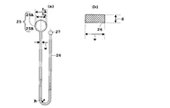
- (A) is a schematic plan view of the U-shaped groove
- (b) is a schematic expanded sectional view of the U-shaped groove
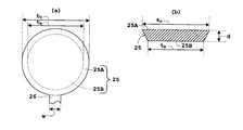
- (A) is a schematic plan view of the opening part concerning an Example
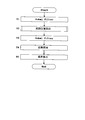
- (b) is a schematic sectional drawing of the opening part concerning an Example. It is the flowchart which showed the flow of a series of blood collection processes which concern on an Example.
- FIG. 9 is a schematic diagram in which a disc (image) of an emphasized contour after the Sobel filter processing relating to step T1 in FIG. 8 is reversed in black and white.
- FIG. 10 is a schematic plan view of a straight line drawing and a disk related to steps U1 to U4 in FIG.
- FIG. 9 is a schematic diagram in which a disc (image) with an emphasized contour after the Sobel filter processing relating to step T3 in FIG. 8 is reversed in black and white.
- FIG. 9 is a schematic diagram in which a disc (image) with an emphasized contour after the Sobel filter processing relating to step T3 in FIG. 8 is reversed in black and white.
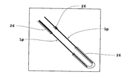
- FIG. 9 is a schematic diagram in which a straight line drawing and a disk related to step T4 in FIG. 8 are reversed in black and white.
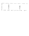
- FIG. 9 is a profile based on a group of straight lines composed of a plurality of straight lines drawn at step T4 in FIG. It is a top view which shows the whole structure of the microchip at the time of the conventional microfluidic device system.
- FIG. 1 is a schematic perspective view of a blood collection device and a measurement device according to an embodiment
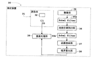
- FIG. 2 is a block diagram of the measurement device according to the embodiment
- FIG. 3 is a schematic perspective view of a scanner in an imaging unit of the measurement device.
- blood will be described as an example of a liquid to be measured, and a system including a blood collection device and a measurement device as a measurement system will be described as an example.
- the blood collection apparatus 10 collects blood to be measured by separating it in time series.
- a measuring device 30 that measures radiation (for example, ⁇ rays, ⁇ rays, etc.) contained in blood collected by the blood collecting device 10 is provided around the blood collecting device 10.
- blood after administration of a radiopharmaceutical into the body of a mouse is collected (ie, blood is collected), and the radiation contained in the blood is measured.
- plasma separation by centrifugation is performed, and radiation contained in the plasma and blood cells separated from the plasma is measured.
- the blood collection apparatus 10 includes a liquid dividing device 40 configured by vertically stacking PDMS substrates 11 and 12 made of two PDMS resins (Polydimethylsiloxane).
- the PDMS substrates 11 and 12 are grooved with a predetermined dimension, and the main flow path 13 and the side paths 41, 42, and 43 are formed by the grooves.
- the material of the blood collection device 10 is not limited to PDMS, and may be any material that is optically transparent such as acrylic, polycarbonate, COP (cycloolefin polymer).
- a catheter 14 is disposed on the blood inlet side of the main flow path 13, and the main flow path 13 and the catheter 14 are connected via a connector 15. Blood is continuously fed from the catheter 14 into the main channel 13 and the amount of inflow is controlled by a valve (not shown).
- a blood pipe 16 is disposed on the blood outlet side of the main flow path 13, and the main flow path 13 and the blood pipe 16 are connected via a connector 17.
- a light source 21 and a photodiode 22 are disposed across the main flow path 13.
- the blood flowing in the main flow path 13 or heparin solution described later is irradiated with light from the light source 21, and the photodiode 22 detects the light shielding by the blood, so that the blood or heparin solution is optically monitored (monitored) as described later.
- Measure length information of blood or heparin solution
- the light source 21 and the photodiode 22 have been described as an example of the optical measurement means.
- any means for measuring the liquid interval while optically monitoring the liquid to be measured can be used as the light source 21 and the photodiode 22. It is not limited.
- volume information of the liquid to be measured may be acquired by a CCD camera.
- the light source 21 and the photodiode 22 are so-called “transmission type sensors” that are arranged to face each other with the main flow channel 13 interposed therebetween as shown in FIG.
- a so-called “reflective sensor” may be used in which light detection means typified by a photodiode is provided on the same side, and detection is performed using reflected light from blood.
- a dispenser 23 is connected to the downstream side of the blood pipe 16 described above.
- the liquid is dropped by the dispenser 23, but a capillary such as an injection needle or a glass tube may be used.
- a disc (also referred to as “CD well”) 24 for receiving and storing blood dropped from the dispenser 23 is provided.
- a plurality of openings 25 for receiving the dropped blood are arranged radially on the center side of the disc 24.
- the circular plate 24 is grooved, and a plurality of U-shaped grooves 26 are formed radially by the grooves.
- Each U-shaped groove 26 is connected to the outer end of the above-described opening 25 on a one-to-one basis, and each U-shaped groove 26 is formed to extend in the radial direction of the disk 24. Yes.
- the disc 24 is formed so that blood can flow through the main flow path 13.
- the disc 24 corresponds to the separating means in the present invention, and also corresponds to the flat plate in the present invention. A specific configuration of the disc 24 will be described later with reference to FIG.
- the measuring device 30 includes a reading unit 31.
- the reading unit 31 is provided with a cover for inserting the exposed imaging plate IP, and detects ⁇ + rays contained in the blood by reading the light excited from the imaging plate IP.
- the reading unit 31 includes a laser light source 32 and a photomultiplier tube (photomultiplier tube) 33, and a laser is applied from the laser light source 32 to the imaging plate IP.
- the photomultiplier tube 33 converts the light excited by the laser irradiation of the imaging plate IP into electrons and multiplies them, thereby detecting ⁇ + rays simultaneously two-dimensionally.
- the imaging plate IP and the reading unit 31 correspond to detection means in the present invention.
- the measuring device 30 includes an imaging unit 34, Sobel filters 35 a and 35 b, a channel position extraction unit 36, a line drawing unit 37, a boundary calculation unit 38, and a superimposition processing unit. 39.
- the imaging unit 34 corresponds to the imaging unit in the present invention
- the Sobel filter 35a, 35b corresponds to the contour emphasizing unit in the present invention
- the flow path position extracting unit 36 corresponds to the flow path position extracting unit in the present invention
- the straight line drawing unit 37 corresponds to the straight line drawing unit in the present invention
- the boundary calculation unit 38 corresponds to the boundary calculation unit in the present invention
- the superimposition processing unit 39 corresponds to the superimposition processing unit in the present invention.
- the former Sobel filter 35a corresponds to the first contour emphasizing means in the present invention
- the latter Sobel filter 35b corresponds to the second contour emphasizing means in the present invention.
- the imaging unit 34 images the disc 24.
- a flat head scanner is employed as the imaging unit 34.
- a flat head scanner is constituted by a linear light source 32a having at least a diameter corresponding to the diameter of the circular plate 24 and a linear photodiode array (that is, a line sensor) 32b arranged to face the light source 32a with the circular plate 24 interposed therebetween.
- the disk 24 is imaged by scanning the disk 24 with a flat head scanner, and an image of the disk 24 is acquired.
- the Sobel filter 35a in the previous stage uses the pixel of interest and its pixel to emphasize the difference in image density as a contour in the U-shaped groove 26 (see FIG. 1) in which the disk 24 is imaged by the imaging unit 34.
- a Sobel filter process is performed as edge enhancement by primary differentiation to obtain a difference from surrounding pixels. The Sobel filter processing by the Sobel filter 35a will be described later with reference to FIG.
- the flow path position extraction unit 36 is based on the design information of the groove 26 and the disc 24 having a predetermined size on the disc 24 imaged by the imaging unit 34, and the pixel position of the contour image emphasized by the Sobel filter 35a. Is adjusted to extract the channel position of the groove 26.
- the channel position extraction by the channel position extraction unit 36 will also be described later with reference to FIG.
- the succeeding Sobel filter 35b performs Sobel filter processing as edge enhancement by primary differentiation in order to enhance the difference in density of the image at the pixel position adjusted by the flow path position extraction unit 36 as a contour.
- Sobel filter processing by the Sobel filter 35b will also be described later with reference to FIG.
- the straight line drawing unit 37 draws a plurality of straight lines parallel to the groove 26 in the contour image emphasized by the Sobel filter 35b.
- the straight line drawing by the straight line drawing unit 37 will also be described later with reference to FIG.
- the boundary calculation unit 38 obtains the boundary of the separated liquid based on a plurality of straight line profiles drawn by the straight line drawing unit 37. In this embodiment, the boundary between plasma and blood cells separated by plasma is determined. The boundary calculation by the boundary calculation unit 38 will also be described later with reference to FIG.
- the superimposition processing unit 39 is imaged by the imaging unit 34, processed through the Sobel filter 35a, the flow path position extraction unit 36, the Sobel filter 35b, the straight line drawing unit 37, and the boundary calculation unit 38, the imaging plate IP, and the reading unit 31. based on the count information of the obtained beta + line in, obtains the count information on beta + lines per unit volume.
- the superimposition processing unit 39 includes the image processed by the imaging unit 34, the Sobel filter 35a, the flow path position extraction unit 36, the Sobel filter 35b, the straight line drawing unit 37, and the boundary calculation unit 38, the imaging plate IP, and the reading
- the superimposing process is performed by superimposing the distribution image of the counting information of the ⁇ + line obtained by the unit 31.
- the plasma and blood cells classified by the boundary calculation unit 38 and the radioactivity concentration of the plasma and blood cells are obtained based on the plasma and blood cells in the distribution image superimposed thereon.
- the liquid dividing device 40 includes the main flow path 13 for feeding blood, the side path 41 for feeding a heparin solution which is a kind of anticoagulant for preventing the occurrence of blood coagulation, A side path 42 for feeding air or gas and a side path 43 for discharging blood or heparin solution are provided.
- a cleaning liquid pipe 44 is arranged on the solution inlet side of the side path 41, and the side path 41 and the cleaning liquid pipe 44 are connected via a connector 45. If necessary, the heparin solution is poured into the main flow path 13 from the cleaning liquid pipe 44 via the side path 41 to clean the flow path. The inflow of heparin solution is controlled by a valve. Anticoagulants are not limited to heparin solutions.
- a bubble pipe 46 is disposed on the gas inlet side of the side path 42, and the side path 42 and the bubble pipe 46 are connected via a connector 47.
- the inflow time of air or gas controlled by a pressure generator (not shown) is adjusted by a valve and sent to the main flow path 13 through the side path 42.
- a pressure generator not shown
- blood is taken out based on blood length information and waste liquid (blood, heparin solution or a mixture thereof) remaining in the flow path of the liquid dividing device 40 is discharged.
- the gas to be fed is not limited, and may be any gas that does not react with blood or heparin solution, as exemplified by rare gas such as helium, neon, and argon, or nitrogen gas.
- the bubble pipe 46 sends gas (for example, air or gas) through the side passage 14 to the main flow path 13 and inserts the gas as bubbles at a specified predetermined interval, whereby the blood to be measured is timed. Separated in series and sent to the disc 24. That is, the bubbles serve as a separator.
- gas for example, air or gas
- the liquid to be measured May use another liquid as a separator.
- a liquid that does not mix with blood such as mineral oil or fluorine oil, may be used as the separator.
- a liquid is used as a separator, it can be used as a separator because it comes into contact with blood, but it is not desirable in that it is sent to the disk 24 and collected.
- a waste liquid pipe 48 is disposed on the side of the waste liquid outlet side of the side path 43, and the side path 43 and the waste liquid pipe 48 are connected via a connector 49.
- the discharge amount is adjusted by a valve, and blood other than blood to be collected, heparin solution after channel cleaning, or a mixed solution thereof is discharged as waste liquid.
- a valve is disposed downstream of the connector 15 of the main flow path 13, and a valve is disposed upstream of the connector 17, the light source 21, and the photodiode 22 of the main flow path 13.
- a valve is disposed downstream of the connector 45 of the side passage 41, and a valve is disposed downstream of the connector 47 of the side passage 42.
- a valve is disposed upstream of the connector 49 in the side passage 43.
- FIG. 4 is a schematic plan view of a disk according to the embodiment
- FIG. 5A is a schematic plan view of a U-shaped groove according to the embodiment
- FIG. FIG. 6A is a schematic enlarged cross-sectional view of such a U-shaped groove
- FIG. 6A is a schematic plan view of an opening according to the embodiment
- FIG. 6B is a schematic cross-section of the opening according to the embodiment.
- the groove 26 of the disk 24 is formed by connecting the opening 25 and the air hole 27 described above.
- the groove 26 extends from the inside to the outside in the radial direction of the disk 24 from the upstream part to the downstream part.
- the U-shape is formed by extending and folding back and extending from the outside toward the inside in the radial direction of the disk 24. A plurality of such U-shaped grooves 26 are provided.
- a motor 28 for rotating the disc 24 is provided at the center of the disc 24. By connecting the rotating shaft 29 of the motor 28 to the disc 24, the centrifugal force of the disc 24 by the motor 28 is used to perform blood separation to separate blood into plasma and blood cells.
- the motor 28 corresponds to the rotating means in this invention.
- the plurality of grooves 26 are arranged radially along the radial direction of the disk 24 as shown in FIG. As described above, each of the plurality of grooves 26 is formed by machining the disk 24 with a predetermined dimension.
- the width of the groove 26 is w, the cross-sectional view of FIG. 5 (b), and FIG. 6 (b).
- the opening 25 is formed in a tapered shape in which the diameter of the upper surface 25A of the opening 25 is t U , the diameter of the lower surface 25B is t B , and the upper surface 25A is wider than the lower surface 25B.
- the radius of curvature of the curved portion when the groove 26 is folded is R.
- the radius of curvature is the distance to the center of the groove 26.
- the circular plate 24 includes an acrylic plate having a thickness of 0.1 mm and 36 grooves 26 each having a width w of 0.5 mm, a depth d of 0.2 mm, and a length of 40 mm. It is formed by overlapping and pressing a 2 mm acrylic plate on top and bottom to form 36 U-shaped grooves 26 (U-shaped minute volume flow paths).
- the diameter of the disk 24 is 104 mm, and the radius of curvature R of the curved portion when the groove 26 is folded is 0.75 mm.
- the inner wall of the groove 26 is subjected to hydrophilic processing using an excimer lamp.
- the diameter t U of the upper surface 25A of the opening 25 is 2.6 mm, that the diameter t B of the lower surface 25B is formed at 1.5 mm, has an upper surface 25A and wider the tapered shape from the lower surface 25B.
- the hydrophilic processing is not limited to the excimer lamp, and is not particularly limited as long as it is a commonly used hydrophilic processing such as chemical processing, plasma processing, and hydrophilic processing by ultraviolet irradiation.
- FIG. 7 is a flowchart showing a flow of a series of blood collection processing according to the embodiment
- FIG. 8 is a flowchart showing a flow of a series of image processing according to the embodiment
- FIG. 9 is related to the embodiment.
- FIG. 10 is a flow chart showing a flow of a series of channel position extraction
- FIG. 10 is a schematic diagram in which an emphasized contour disk (image) after the Sobel filter processing relating to step T1 in FIG.
- FIG. 11 is a schematic plan view of a straight line drawing and a disk related to steps U1 to U4 in FIG. 9, and FIG.
- FIG. 12 is a disk with an emphasized contour (after the Sobel filter processing related to step T3 in FIG. 8).
- 13 is a schematic diagram in which the image is reversed in black and white
- FIG. 13 is a schematic drawing in which the straight line drawing and the disk in black and white are reversed in FIG. 8, and
- FIG. 14 is depicted in step T4 in FIG. Consisting of multiple straight lines It is a profile based on a group of lines.
- Step S1 Blood is fed into the main flow path
- the catheter 14 (see FIG. 1) is inserted into the mouse artery, and the arterial blood self-extracted by the mouse blood pressure is passed through the catheter 14 through the main flow path 13 (FIG. 1). The blood is continuously fed into the main flow path 13 by guiding to the reference).
- Step S2 Separation Control of Separator
- a photodiode 22 disposed opposite the light source 21 (see FIG. 1) with the main flow path 13 interposed therebetween. Since the light emitted from the light source 21 is incident on the detector signal, the detector signal photoelectrically converted by the photodiode 22 becomes a high level and is output from the photodiode 22. Conversely, when blood is flowing through the main flow path 13, the light emitted from the light source 21 is blocked by the blood, so that the light is not incident on the photodiode 22, and the detector signal becomes a low level and photo Output from the diode 22.
- the photodiode 22 detects light shielding by blood
- the blood length information is measured while optically monitoring the blood
- the valve is turned on based on the measurement result by the photodiode 22.
- Control By controlling the valve, the interval of air or gas sent from the side passage 42 to the main channel 13, that is, the interval of the separator is controlled. Since the main channel 13 is formed by grooving with a predetermined dimension, the volume of blood to be taken out can be obtained from the blood length information obtained by optical monitoring (monitoring).
- Step S3 Transfer to Disk A trace amount of blood taken out in step S2 is sent to the dispenser 23 (see FIG. 1) via the blood piping 16 (see FIG. 1).
- the dispenser 23 drops each small amount of blood taken out into the opening 25 (see FIG. 1) of the disc (CD well) 24 (see FIG. 1). By this dripping, the extracted trace blood is transferred to the disc 24.
- Step S4 End of Blood Collection It is determined whether or not blood collection is completed at a predetermined time. If blood collection has not ended, the process returns to step S1. If the blood collection has been completed, the process proceeds to the next step S5.
- Step S5 Plasma Separation After all blood collection at a predetermined time is completed, when blood is transferred to the disc 24 (see FIG. 1), plasma separation is performed by rotating the disc 24 to separate it into plasma and blood cells. Do.
- the catheter 14 (see FIG. 1) is washed or a heparin solution, air or gas is fed into the waste liquid (blood, heparin solution or a mixture thereof) remaining in the flow path of the liquid dividing device 40. (Liquid) is discharged.
- Step S6 Imaging of discs
- Each disc 24 (see FIG. 1) plasma-separated into plasma and blood cells is stored as a sample by opening a cassette (not shown) on the imaging plate IP (see FIG. 1) and the cassette is closed for exposure.
- electrons are captured by lattice defects of the phosphor (not shown) of the imaging plate IP due to the ionizing ability of ⁇ + rays contained in the blood.
- the imaging plate IP is taken out from the cassette, inserted into the cover portion of the reading unit 31 (see FIG. 1) of the measuring device 30 (see FIG. 1), and the imaging plate IP is irradiated with light. Perform exposure.
- a laser is irradiated from the laser light source 32 (see FIG. 1) of the reading unit 31 (see FIG. 1) to the imaging plate IP (see FIG. 1).
- the trapped electrons are excited to the conductor by this irradiation and recombine with holes, and are excited as light from the phosphor.
- the photomultiplier tube 33 (see FIG. 1) converts the light excited by the laser irradiation to the imaging plate IP into electrons and multiplies it, so that it is simultaneously detected and counted two-dimensionally as an electric pulse. .
- the captured electrons are erased by irradiating the imaging plate IP with light from an erasing light source (not shown) for reuse. Based on the count information of the obtained beta + line in the imaging plate IP and reading unit 31, obtains the radiation dose in the blood which is count information on beta + line.
- the imaging unit 34 (see FIG. 2 and FIG. 3) images the plasma and blood cells separated from each plasma for each disc 24 (see FIG. 1).
- plasma and blood cells appear as a difference in density on the imaged image due to the difference in absorbance and easily on the image. Be identifiable.
- the density difference that is, the difference in absorbance
- the unit 37 and the boundary calculation unit 38 perform image processing.
- Step S7 Image Processing The image processing in step S7 will be described with reference to the flowchart of FIG.
- Step T1 Sobel filter
- the Sobel filter 35a in the previous stage performs Sobel filter processing in order to emphasize the density difference of the image in the separated blood on the disc 24 imaged by the imaging unit 34 as an outline.
- Nine pixels composed of 3 ⁇ 3 pixels in the vertical and horizontal directions are extracted from the captured image, and a matrix operation is performed on these pixels as shown in the following equation (1).
- P is an arrangement of pixel values p 11 , p 12 , p 13 , p 21 , p 22 , p 23 , p 31 , p 32 , and p 33 of 9 pixels arranged vertically and horizontally 3 ⁇ 3. but, the central pixel p 22, and the target pixel to be subjected to Sobel filter process. That, Sobel filter35a is, including subsequent Sobel filter35b, one obtains a difference between the target pixel p 22 and its peripheral pixels p 11, p 12, p 13 , p 21, p 23, p 31, p 32, p 33 primary Performs edge enhancement by differentiation.
- the Sobel filter is divided into a horizontal matrix Gh and a vertical matrix Gv, respectively, and a calculation using Gh and Gv is performed on the target pixel and its peripheral pixels.
- the target pixel value ph 22 after the horizontal matrix Gh calculation and each pixel value pv 22 after the vertical matrix Gv calculation are expressed by the above equation (2).
- the other pixels are obtained by using the same method, so that the Sobel filter processing by the Sobel filter 35a is performed, and the contrast of the image is emphasized as an outline.
- the image of the disc 24 with the emphasized contour after the Sobel filter processing by the Sobel filter 35a is as shown in FIG. In practice, black and white are reversed, but for convenience of illustration, in FIG. As shown in FIG. 10, the outline of the disk 24 is emphasized. It should be noted that in this stage at step T1, since everything contained in the disc 24 is emphasized, the outlines of the plasma and blood cell regions are not sufficiently emphasized. Therefore, further processing after step T2 is performed to obtain the boundary between plasma and blood cells.
- Step T2 Channel Position Extraction
- the channel position extraction unit 36 is based on the design information of the groove 26 and the disc 24 having a predetermined dimension in the disc 24 imaged by the imaging unit 34, and the Sobel in step T1.
- the flow path position of the groove 26 is extracted by adjusting the pixel position of the contour image emphasized by the filter 35a.
- the flow path position extraction by the flow path position extraction unit 36 in step T2 will be described with reference to the flowchart of FIG.
- Step U1 L (0) Drawing
- a straight line is drawn with respect to two opposing flow paths (grooves 26).
- the position where the straight line overlaps the edges (contours) of the two opposing flow paths (grooves 26) is searched while shifting the position and angle of the straight line. Since the outline of the groove 26 is emphasized in the blood cell region, it is easy to draw a straight line by searching for the position where the straight lines overlap most.
- L (0) as shown in FIG.
- Step U3 L ( ⁇ ) Drawing A straight line L ( ⁇ ) is drawn with respect to the groove 26 as the entire flow path while rotating the straight line by ⁇ [rad].
- Step U4 All drawings? It is determined whether or not all the straight lines L ( ⁇ ) have been drawn. If all are drawn, the process proceeds to the next step U5. If the drawing has not been completed, the process returns to step U3, and steps U3 and U4 are repeated until all (in this case, a total of 18) straight lines L ( ⁇ ) are drawn.
- Step U5 Extraction of groove region Based on the design information of the groove 26 and the disk 24, it is outside the intersection (center of the disk 24) of the straight lines L (0) and L ( ⁇ / 2) obtained in Step U2.
- an image of the disk 24 on which a straight line as shown in FIG. 11 is drawn is created.
- the intersection (the center of the disk 24) of the straight lines L (0) and L ( ⁇ / 2) obtained in step U2 and the straight line L is extracted from ⁇ ).
- Step U6 Moving Pixel Since there is an error in the groove region (flow channel region) extracted in Step U5, the pixel in the region is moved horizontally or rotationally up, down, left and right.
- Step U7 Maximum number of pixels?
- the pixel is moved, and it is determined whether or not the number of blood cells included in the region is maximized. Specifically, while moving the blood cell portion in the contour image emphasized in step T1, the number of pixels at the location where the moved blood cell portion overlaps the groove region of the design information is checked. If it is the maximum, the region consisting of the pixel position with the maximum number of pixels is regarded as the correct groove region, and the flow channel position extraction by the flow channel position extraction unit 36 consisting of a series of steps U1 to U7 is terminated.
- step U6 If it is not the maximum, it is determined that there is an error, and the process returns to step U6, where a plurality of movement candidates having a larger number of pixels than the predetermined value are listed until the number of pixels of the blood cell is maximized, The largest candidate is extracted from Steps U6 and U7.
- the flow path position extraction unit 36 adjusts the pixel position of the contour image emphasized by the Sobel filter 35a based on the design information of the groove 26 and the disk 24. Subsequently, returning to the flowchart of FIG.
- Step T3 Sobel filter
- the succeeding Sobel filter 35b performs Sobel filter processing in order to emphasize the contrast of the image at the pixel position adjusted by the flow path position extraction unit 36 as a contour. Since specific Sobel filter processing is performed using the above equations (1) and (2) as described in the preceding Sobel filter 35a, the description thereof is omitted.
- Step T4 Straight Line Drawing
- the straight line drawing unit 37 draws a plurality of straight lines parallel to the groove 26 as shown in FIG. 13 in the contour image emphasized by the Sobel filter 35b in Step T3 (in FIG. 13, the straight line group Lp is drawn). Draw).
- straight line groups Lp composed of a plurality of straight lines are respectively drawn along the radial direction.
- a profile based on the straight line group Lp is as shown in FIG. The horizontal axis of the profile is the length of the diameter, and “0” is the center of the disk 24.
- Step T5 Boundary Calculation
- the boundary calculation unit 38 obtains a boundary between plasma and blood cells separated by plasma based on a plurality of straight line profiles (see FIG. 14) drawn by the straight line drawing unit 37 in step T4.
- the region from the horizontal axis “0” to the peak position appearing on the center side is the air region
- the region from the peak position appearing on the center side to the peak position appearing outside is the plasma region, and the peak appearing outside.
- a region outside the position from the position is a blood cell region. Since the profile relates to a straight line group Lp composed of a plurality of straight lines, peak positions corresponding to the boundaries also appear at a plurality of locations. Therefore, by determining the average of these peak positions, the boundary between air and plasma is determined, and the boundary between plasma and blood cells is determined.
- the Sobel filter 35a As described above, by performing steps T1 to T5, the Sobel filter 35a, the flow path position extracting unit 36, the Sobel filter 35b, and the straight line drawing are performed based on the density difference of the image in the groove 26 of the disk 24 imaged by the imaging unit 34.
- the unit 37 and the boundary calculation unit 38 perform image processing. Subsequently, returning to the flowchart of FIG.
- Step S8 Superimposition Processing
- the superimposition processing unit 39 counts the image captured by the imaging unit 34 in step S6 and processed in the image processing in step S7, and the ⁇ + rays obtained by the imaging plate IP and the reading unit 31. Based on the information, in order to obtain the ⁇ + ray count information per unit volume, the image processed by the image processing and the ⁇ + ray count information distribution image are superimposed to perform superposition processing.
- the plasma / blood cell region is moved up and down, left and right, and ⁇ + ray counting information (IP image) obtained by the imaging plate IP and the reading unit 31 and The position where the overlap of the maximum is obtained is obtained as the superposition position, and the superposition process is performed.
- the volume of the plasma and blood cells sorted by the boundary calculation unit 38 in step T5 is obtained, respectively, and the count information of ⁇ + rays in the plasma and blood cells in the distribution image superimposed on the plasma and blood cells is obtained.
- the radioactivity concentration which is ⁇ + ray count information per unit volume, is obtained for each plasma and blood cell.
- the boundary calculation means in this embodiment, the boundary of plasma / blood cells or air / plasma that is imaged by the imaging means (imaging unit 34 in this embodiment) is obtained.
- a boundary calculation unit 38 By providing such a boundary calculation means (boundary calculation unit 38), the boundary of the separated liquid (plasma / blood cell or air / plasma boundary) can be known, and the separated liquid region (air / The area of plasma and blood cells) is accurately identified.
- the separating means is preferably a flat plate (in the present embodiment, a circular plate 24) that is grooved with a predetermined dimension. That is, since the groove is processed with a predetermined dimension, the boundary of the liquid (the boundary of plasma / blood cells or air / plasma in this embodiment) sent to the flat plate (disk 24) is calculated as the boundary calculation means (this embodiment). Then, if the boundary calculation unit 38) obtains, the area of the groove 26 or the volume of the groove 26 which is divided and grooved with a predetermined dimension can be defined.
- the flat plate is a flat disk 24, and grooves are radially formed with a predetermined dimension along the radial direction of the disk 24 as shown in FIG.
- a rotating means (motor 28 in this embodiment) for rotating the disk 24 is provided at the center of the disk 24, and the liquid to be measured is utilized by utilizing the centrifugal force of the disk 24 by the rotating means (motor 28). (Blood in this embodiment) is centrifuged.
- the liquid to be measured is blood, and plasma that is separated into plasma and blood cells by centrifuging the blood using the centrifugal force of the flat plate (disk 24) by the rotating means (motor 28). Separation is taking place.
- the boundary calculation means (boundary calculation unit 38) obtains the boundary. In the case where the boundary calculation means (boundary calculation unit 38) obtains the boundary by using such a difference in light and shade of the image, the following is performed in this embodiment.
- contour emphasizing means for emphasizing the density difference of the image in the separated liquid by the separating means (the disk 24 in the present embodiment) imaged by the imaging means (imaging unit 34 in the present embodiment) as a contour.
- the preceding stage Sobelafilter 35a is provided, and the boundary calculation means (boundary calculation unit 38) obtains the boundary based on the contour image emphasized by the contour enhancement means (Sobel filter 35a).
- the contour image emphasized by the contour emphasizing means Sobel filter 35a
- the boundary can be easily obtained accurately.
- the separating means (disk 24 in this embodiment) is a flat plate (disk 24 in this embodiment) that is grooved with a predetermined dimension, and is imaging means (image pickup in this embodiment).
- a contour enhancement means (Sobel filter 35a in the previous stage in the present embodiment) for emphasizing the density difference of the image in the liquid separated by the separation means (the disk 24 in the present embodiment) imaged by the section 34)
- the boundary calculation unit (boundary calculation unit 38) obtains the boundary based on the contour image enhanced by the contour enhancement unit (Sobel filter 35a).
- the measurement system further includes a flow path position extracting means (in the present embodiment, the flow path position extracting section 36).
- This flow path position extracting means is based on the design information of the groove 26 and the flat plate (disk 24) having a predetermined dimension on the flat plate (disk 24), and the contour emphasizing means (the book).
- the channel position of the groove 26 is extracted by adjusting the pixel position of the groove 26 in the contour image emphasized by the preceding Sobel filter 35a).
- the boundary calculating means obtains the boundary based on the image at the pixel position adjusted by the flow path position extracting means (flow path position extracting section 36).
- the boundary calculating means obtains the boundary based on the image at the pixel position adjusted by the flow path position extracting means (flow path position extracting section 36).
- design information of the groove 26 and the flat plate (disk 24) is known in advance, in other words, based on this design information.
- the flat plate (disk 24) is grooved with a predetermined dimension.
- the contour emphasizing means Sobel (filter 35a) is provided and the flow path position extracting means (flow path position extracting unit 36) is not provided, not only the groove 26 (flow path) but also a flat plate (disc 24). Since the contour emphasizing means (Sobel filter 35a) is used to enhance the contour of the liquid (blood in this embodiment), the contour of the region (plasma and blood cells in this embodiment) is sufficiently emphasized. Not. Therefore, the flow path position of the groove 26 is extracted by the flow path position extraction means (flow path position extraction unit 36) by adjusting the pixel position, so that the contour of the region of blood (blood) to be classified (plasma and blood cells) Area) is sufficiently emphasized, and the boundary is easily obtained.
- the flow path position extraction means adjusts the pixel position using such design information
- contour emphasis means in the present embodiment, a subsequent stage is used to emphasize the image density difference at the pixel position adjusted by the flow path position extracting means (the flow path position extracting unit 36 in the present embodiment) as an outline.
- the boundary calculating unit in this embodiment, the boundary calculating unit 38) obtains the contour emphasized by the contour emphasizing unit (Sobel filter 35b) as a boundary. In this case, since the contour emphasized by the contour emphasizing means (Sobel filter 35b) is obtained as a boundary, the boundary can be found more accurately.
- contour emphasis means in the present embodiment, a subsequent stage is used to emphasize the image density difference at the pixel position adjusted by the flow path position extracting means (the flow path position extracting unit 36 in the present embodiment) as an outline.
- a straight line drawing unit in this embodiment, a straight line drawing unit 37
- a boundary calculation unit in this embodiment, the boundary calculation unit 38
- contour emphasis means in this embodiment, the latter stage emphasizes the difference in image density at the pixel position adjusted by the flow path position extraction means (flow path position extraction unit 36 in this embodiment).
- the contour emphasizing means Sobel filter 35b
- the contrast of the image in the separated liquid (blood in this embodiment) on the flat plate (in this embodiment, the disk 24) imaged by the imaging means (imaging section 34 in this embodiment) is emphasized as an outline.
- the contour emphasizing means (the former Sobel filter 35a in this embodiment) is the first contour emphasizing means (the previous Sobel filter 35a).
- This first contour emphasizing means (Sobel filter 35a) is a preceding stage that emphasizes the contrast of the image in the separated liquid (blood) on the flat plate (disk 24) imaged by the imaging means (imaging unit 34) as an outline.
- Contour emphasizing means (Sobelafilter 35a)
- the second contour emphasizing means (Sobel ⁇ ⁇ ⁇ filter 35b) using the difference in image density at the pixel position adjusted by the channel position extracting means (channel position extracting unit 36) as the contour.
- the contour enhancement by the second contour enhancement means (Sobel filter 35b) is performed after the contour enhancement by the first contour enhancement means (Sobel filter 35a). The boundary is easily obtained by performing the edge enhancement twice.
- the contour emphasizing means includes the pixel of interest (center pixel p 22 in this embodiment) and its peripheral pixels (peripheral pixels p 11 , p 12 , p 13 , p 21 , p 23 , p in this embodiment). 31 , p 32 , and p 33 ) are used to perform edge enhancement by primary differentiation. In this embodiment, a Sobel filter is used as edge enhancement by first-order differentiation.
- detection means imaging plate in this embodiment
- detection means that simultaneously detects two-dimensionally the radiation contained in the liquid to be measured (blood in this embodiment) and obtains two-dimensional image information of the radiation.
- an image of the separated liquid (blood) in the separating means captured by the imaging means (in this embodiment, the imaging section 34), and the detecting means.
- Superimposition processing means (superimposition processing section 39 in this embodiment) that performs superimposition processing by superimposing the distribution image of the two-dimensional image information obtained by (imaging plate IP and reading section 31), and includes boundary calculation means (this In the embodiment, the region of the liquid (blood) divided by the boundary calculation unit 38) (the region of air / plasma / blood cells in this embodiment) and the region (air / plasma / blood cell region) in the distribution image superimposed thereon Based on Seeking (count information on beta + line) radiation information in the region. Since such superposition processing is performed, information on radiation in the region can be accurately obtained.
- the separating means disk 24 in this embodiment
- the boundary calculating means boundary calculating section 38 in this embodiment
- the detection means imaging plate IP and reading unit 31 in this embodiment simultaneously detects the radiation contained in the blood two-dimensionally to obtain the two-dimensional image information of the radiation, and performs the superimposition process.
- the means (superimposition processing unit 39) performs superimposition processing by superimposing the plasma-separated image and the distribution image of the two-dimensional image information obtained by the detection means (imaging plate IP and reading unit 31), and calculates a boundary. Based on the plasma and blood cells of blood divided by the means (boundary calculation unit 38) and the plasma and blood cells in the distribution image superimposed thereon, the radioactivity concentrations of the plasma and blood cells are obtained.
- the present invention is not limited to the above embodiment, and can be modified as follows.
- the measurement target liquid is not limited to blood and includes radioactive substances and fluorescent agents. Or a liquid mixture used in an analyzer.
- the detection means imaging plate IP and reading unit 31 in the embodiment
- the detection means simultaneously detects light contained in the liquid two-dimensionally to detect the light. If two-dimensional image information is obtained, and the concentration of the fluorescent substance in the region is obtained based on the region of the liquid divided by the boundary calculating means (in the embodiment, the boundary calculating unit 38) and the region in the distribution image superimposed thereon. Good.
- the separation means is a flat plate (disk 24 in the embodiment) grooved with a predetermined dimension, but has a structure for separating the liquid to be measured (blood in the embodiment). If there is, it is not limited to a flat plate.
- the disk 24 and the rotating means are provided in order to apply the centrifugal separation of the liquid (blood in the embodiment) in the liquid collection (blood collection in the embodiment).
- the disk 24 and the rotating means are not necessarily provided.
- the flat plate is not limited to the circular plate 24 but may be a square plate, a polygonal plate, or the like, but it is preferable that the center of rotation has a center of gravity considering rotation.
- a plurality of grooves 26 formed in the radial direction are provided by radially processing the grooves along the radial direction of the disk 24. Absent. For example, you may arrange
- the boundary calculation means obtains the boundary, but the contour enhancement means (Sobel filters 35a and 35b in the embodiment) and the flow path position extraction means in the previous stage.
- the flow path position extraction unit 36 and straight line drawing means (in the embodiment, the straight line drawing unit 37) are provided, but it is not necessary to provide all of them.
- the Sobel filter that performs contour enhancement by primary differentiation to obtain the difference between the pixel of interest and its surrounding pixels
- the contour enhancement by the first derivative but may be a Laplacian filter (Laplacian filter) or the like as the contour enhancement by the second derivative to obtain a further difference between the target pixel and the surrounding pixels.
- the contour enhancement by differentiation is not limited to the Sobel filter, but may be a Prewitt filter. Thus, if it is the means of outline emphasis used normally, it will not be limited to the outline emphasis by primary differentiation and secondary differentiation.
- detection means imaging plate IP and reading unit 31 in the embodiment
- superimposition processing means that simultaneously detects light or radiation two-dimensionally to obtain two-dimensional image information of light or radiation
- superimposition processing means In the embodiment, the superimposing processing unit 39
- the detecting unit and the superimposing processing unit are not necessarily provided.
- the optical imaging unit such as a flat head scanner has been described as an example of the imaging unit.
- the imaging unit may be a radiation imaging unit including a radiation irradiation unit and a radiation detection unit.
- the radioactivity concentration is different in each part of the centrifuged liquid, and the different points are used.
- the detection means (imaging plate IP and reading unit 31 in the embodiment) simultaneously detects (simultaneously counts) radiation contained in the liquid to be measured (blood in the embodiment).
- a liquid containing a fluorescent agent may be used.
- a fluorescent substance that is a fluorescent agent is included in the liquid, and the measuring device measures light generated from the fluorescent substance with a CCD camera or the like. Therefore, the information of light per unit volume is accurately obtained.
- a two-dimensional radiation sensor such as a scintillator array and a photomultiplier or a semiconductor detector
- the light generated from the luminescent material may be measured in the same manner.
- the present invention is suitable for a measurement system that measures light emitted from a luminescent or fluorescent substance contained in a liquid to be measured or radiation contained in the liquid to be measured.
Landscapes
- Health & Medical Sciences (AREA)
- Life Sciences & Earth Sciences (AREA)
- Physics & Mathematics (AREA)
- Engineering & Computer Science (AREA)
- General Health & Medical Sciences (AREA)
- Pathology (AREA)
- Hematology (AREA)
- Biomedical Technology (AREA)
- Chemical & Material Sciences (AREA)
- Molecular Biology (AREA)
- Biophysics (AREA)
- Surgery (AREA)
- Animal Behavior & Ethology (AREA)
- Medical Informatics (AREA)
- Public Health (AREA)
- Veterinary Medicine (AREA)
- Heart & Thoracic Surgery (AREA)
- Immunology (AREA)
- Analytical Chemistry (AREA)
- Biochemistry (AREA)
- General Physics & Mathematics (AREA)
- Manufacturing & Machinery (AREA)
- Dispersion Chemistry (AREA)
- Optics & Photonics (AREA)
- Food Science & Technology (AREA)
- Medicinal Chemistry (AREA)
- Urology & Nephrology (AREA)
- Chemical Kinetics & Catalysis (AREA)
- Ecology (AREA)
- Nuclear Medicine, Radiotherapy & Molecular Imaging (AREA)
- Investigating Or Analysing Biological Materials (AREA)
- Investigating, Analyzing Materials By Fluorescence Or Luminescence (AREA)
- Automatic Analysis And Handling Materials Therefor (AREA)
- Measurement Of Radiation (AREA)
- Nuclear Medicine (AREA)
Abstract
Disclosed is a measurement device provided with a boundary calculation unit, which, with an image created by an imaging unit, requests a boundary between isolated plasma and blood cells, or between air and plasma. By being provided with such a boundary calculation unit, it is possible to know the boundary between isolated plasma and blood cells or air and plasma, and it is possible to accurately know the regions of isolated air, plasma and blood cells. The device is further provided with a line drawing unit for drawing a plurality of straight lines parallel to the groove of a disk for isolating plasma. Specifically, in photographed images, the boundary calculation unit requests boundaries based on the profile of a plurality of straight lines drawn by the line drawing unit, thereby making the requesting of boundaries easier.
Description
この発明は、測定対象の液体中に含まれている発光あるいは蛍光物質から発生した光あるいは測定対象の液体中に含まれている放射線を測定する測定システムに関する。
The present invention relates to a measurement system for measuring light generated from luminescent or fluorescent substances contained in a liquid to be measured or radiation contained in the liquid to be measured.
測定システムは、例えば液体採取装置に用いられる。液体採取装置として、血液を採取する、すなわち採血する採血装置を例にとって説明する。採血装置は、核医学診断(例えば、PET(Positron Emission Tomography)、SPECT(Single Photon Emission CT)など)における定量解析で用いられ、特に小動物(例えばマウスやラットなど)の動脈血中の放射能濃度の測定に用いられている。従来、上述した小動物の定量解析では、以下のような(a)~(d)の方式が採用されている。
Measured system is used, for example, in a liquid sampling device. As an example of the liquid collection device, a blood collection device that collects blood, that is, collects blood will be described. Blood collection devices are used for quantitative analysis in nuclear medicine diagnosis (eg, PET (Positron Emission Tomography), SPECT (Single Photon Emission CT), etc.), and in particular, the concentration of radioactivity in arterial blood of small animals (eg mice and rats). Used for measurement. Conventionally, the following methods (a) to (d) have been employed in the above-described quantitative analysis of small animals.
(a)手採血
マウス動脈に挿入したカテーテルの他端から、血圧によって自出された血液を適当な容器に受け取る。続いて、容器内の血液のうち一定体積を定量ピペットによって吸い上げ、吸い上げられた血液中の放射線を計数(すなわちカウント)して、全血中放射能濃度を測定する。さらに、容器内に残った血液を遠心分離させて血漿を得て、同様に、定量ピペットによって採取して、血漿中放射能濃度を測定する。 (a) Manual blood collection From the other end of the catheter inserted into the mouse artery, blood drawn by blood pressure is received in a suitable container. Subsequently, a certain volume of blood in the container is sucked up by a quantitative pipette, and radiation in the sucked blood is counted (that is, counted) to measure the radioactivity concentration in whole blood. Furthermore, the blood remaining in the container is centrifuged to obtain plasma, which is similarly collected by a quantitative pipette to measure the plasma radioactivity concentration.
マウス動脈に挿入したカテーテルの他端から、血圧によって自出された血液を適当な容器に受け取る。続いて、容器内の血液のうち一定体積を定量ピペットによって吸い上げ、吸い上げられた血液中の放射線を計数(すなわちカウント)して、全血中放射能濃度を測定する。さらに、容器内に残った血液を遠心分離させて血漿を得て、同様に、定量ピペットによって採取して、血漿中放射能濃度を測定する。 (a) Manual blood collection From the other end of the catheter inserted into the mouse artery, blood drawn by blood pressure is received in a suitable container. Subsequently, a certain volume of blood in the container is sucked up by a quantitative pipette, and radiation in the sucked blood is counted (that is, counted) to measure the radioactivity concentration in whole blood. Furthermore, the blood remaining in the container is centrifuged to obtain plasma, which is similarly collected by a quantitative pipette to measure the plasma radioactivity concentration.
(b)動脈流路β線検出器
動脈血流路にβ+線検出器を設置することで、血中放射能濃度を測定する。β+線をプラスチックシンチレータやPINダイオードで検出する。例えば、非特許文献1では、ダイオードは、長さが30[mm]の細長い形状を有し、長辺方向に沿って血液が入ったチューブを配管することで、検出可能面積を増加させ、検出効率を確保している。 (b) Arterial channel β-ray detector A blood + radioactivity concentration is measured by installing a β + -ray detector in the arterial blood channel. The β + line is detected with a plastic scintillator or PIN diode. For example, in Non-PatentDocument 1, the diode has an elongated shape with a length of 30 [mm], and a tube containing blood along the long side direction is connected to increase the detectable area, thereby detecting the diode. Ensures efficiency.
動脈血流路にβ+線検出器を設置することで、血中放射能濃度を測定する。β+線をプラスチックシンチレータやPINダイオードで検出する。例えば、非特許文献1では、ダイオードは、長さが30[mm]の細長い形状を有し、長辺方向に沿って血液が入ったチューブを配管することで、検出可能面積を増加させ、検出効率を確保している。 (b) Arterial channel β-ray detector A blood + radioactivity concentration is measured by installing a β + -ray detector in the arterial blood channel. The β + line is detected with a plastic scintillator or PIN diode. For example, in Non-Patent
(c)微小流体素子方式
マウス血圧にて自出された動脈血を、図15に示すようにマイクロチップ(素子)MC上に導く方式である。マイクロチップMCには、1本の主流路FM、選択可能な支流路FB、および流路洗浄や血液排出用に使用するヘパリン(heparin)溶液と生理食塩水の混合液Hを流し込み、あるいは使用されたヘパリン溶液と生理食塩水の混合液Hや血液Bを流し出すための側路FNを配設している。支流路FBの各々の先には容器を配設しており、支流路FBのいずれか1つが、マイクロチップMCに供給されるアルゴンガスGasのガス圧、マイクロチップMCのメカニズムによって選択されるように構成されている。支流路FBのいずれか1つが選択された状態で血液Bを流し込む。マイクロチップMCの各支流路は内部を陰圧にし、さらに蠕動ポンプを搭載することで血液Bやヘパリン溶液と生理食塩水の混合液Hの流速を上げている。各々の流路FM,FBが、マイクロチップMCに対して所定の寸法で溝加工したもので形成されており、流し込まれた血液Bの溝長あるいは溝領域がわかれば、その血液Bの微小体積が規定されるのがマイクロチップMCの特徴である。その規定された微小体積によって、予め定められた体積の血液Bが流路内に満ちた状況で、ヘパリン溶液と生理食塩水の混合液Hの圧入によって所定の受け容器(図示省略)に血液Bをヘパリン溶液と生理食塩水の混合液Hとともに送り込む。その後、各流路FM,FBをヘパリン溶液と生理食塩水の混合液Hで洗浄し、次の採血に備える。受け容器内の血液Bを、生理食塩水とともに別容器に洗い出し、ウェルカウンタによって血液B中の放射線を計数する(例えば、非特許文献2、3、特許文献1参照)。 (c) Microfluidic device method In this method, arterial blood spontaneously produced by mouse blood pressure is guided onto a microchip (device) MC as shown in FIG. The microchip MC is fed with one main flow channel F M , a selectable branch flow channel F B , and a mixed solution H of heparin solution and physiological saline used for flow channel cleaning and blood discharge, or They are arranged side path F N for bleeding the mixture H and blood B heparin solution and saline was used. To each of the previous branch flow paths F B are disposed a container, one of the branch flow paths F B, argon gas Gas pressure of gas supplied to the microchip MC, it is selected by the mechanism of the microchip MC It is comprised so that. Pouring the blood B in one of the branch flow paths F B has been selected. Each branch channel of the microchip MC has a negative pressure inside, and a peristaltic pump is mounted to increase the flow rate of the mixed solution H of blood B, heparin solution and physiological saline. Each flow path F M, F B is, are formed in those grooves in a predetermined size with respect to the microchip MC, knowing the groove length or groove area of the blood B was poured, the blood B It is a feature of the microchip MC that a minute volume is defined. In a situation where a predetermined volume of blood B is filled in the flow path due to the defined minute volume, blood B is put into a predetermined receiving container (not shown) by press-fitting the mixture H of heparin solution and physiological saline. Is fed together with a mixture H of heparin solution and physiological saline. Then, each flow path F M, washing the F B in a mixture H heparin solution and saline to prepare for the next blood collection. The blood B in the receiving container is washed out in a separate container together with physiological saline, and the radiation in the blood B is counted by a well counter (see, for example,Non-Patent Documents 2 and 3 and Patent Document 1).
マウス血圧にて自出された動脈血を、図15に示すようにマイクロチップ(素子)MC上に導く方式である。マイクロチップMCには、1本の主流路FM、選択可能な支流路FB、および流路洗浄や血液排出用に使用するヘパリン(heparin)溶液と生理食塩水の混合液Hを流し込み、あるいは使用されたヘパリン溶液と生理食塩水の混合液Hや血液Bを流し出すための側路FNを配設している。支流路FBの各々の先には容器を配設しており、支流路FBのいずれか1つが、マイクロチップMCに供給されるアルゴンガスGasのガス圧、マイクロチップMCのメカニズムによって選択されるように構成されている。支流路FBのいずれか1つが選択された状態で血液Bを流し込む。マイクロチップMCの各支流路は内部を陰圧にし、さらに蠕動ポンプを搭載することで血液Bやヘパリン溶液と生理食塩水の混合液Hの流速を上げている。各々の流路FM,FBが、マイクロチップMCに対して所定の寸法で溝加工したもので形成されており、流し込まれた血液Bの溝長あるいは溝領域がわかれば、その血液Bの微小体積が規定されるのがマイクロチップMCの特徴である。その規定された微小体積によって、予め定められた体積の血液Bが流路内に満ちた状況で、ヘパリン溶液と生理食塩水の混合液Hの圧入によって所定の受け容器(図示省略)に血液Bをヘパリン溶液と生理食塩水の混合液Hとともに送り込む。その後、各流路FM,FBをヘパリン溶液と生理食塩水の混合液Hで洗浄し、次の採血に備える。受け容器内の血液Bを、生理食塩水とともに別容器に洗い出し、ウェルカウンタによって血液B中の放射線を計数する(例えば、非特許文献2、3、特許文献1参照)。 (c) Microfluidic device method In this method, arterial blood spontaneously produced by mouse blood pressure is guided onto a microchip (device) MC as shown in FIG. The microchip MC is fed with one main flow channel F M , a selectable branch flow channel F B , and a mixed solution H of heparin solution and physiological saline used for flow channel cleaning and blood discharge, or They are arranged side path F N for bleeding the mixture H and blood B heparin solution and saline was used. To each of the previous branch flow paths F B are disposed a container, one of the branch flow paths F B, argon gas Gas pressure of gas supplied to the microchip MC, it is selected by the mechanism of the microchip MC It is comprised so that. Pouring the blood B in one of the branch flow paths F B has been selected. Each branch channel of the microchip MC has a negative pressure inside, and a peristaltic pump is mounted to increase the flow rate of the mixed solution H of blood B, heparin solution and physiological saline. Each flow path F M, F B is, are formed in those grooves in a predetermined size with respect to the microchip MC, knowing the groove length or groove area of the blood B was poured, the blood B It is a feature of the microchip MC that a minute volume is defined. In a situation where a predetermined volume of blood B is filled in the flow path due to the defined minute volume, blood B is put into a predetermined receiving container (not shown) by press-fitting the mixture H of heparin solution and physiological saline. Is fed together with a mixture H of heparin solution and physiological saline. Then, each flow path F M, washing the F B in a mixture H heparin solution and saline to prepare for the next blood collection. The blood B in the receiving container is washed out in a separate container together with physiological saline, and the radiation in the blood B is counted by a well counter (see, for example,
(d)PET画像からの放射能時間変化計測
撮像されたPETのダイナミック画像の左心室に関心領域を設定して、その領域内の放射能濃度の時間変化を求める手法である(例えば、非特許文献4参照)。 (d) Measurement of radioactivity time change from PET image This is a method of setting a region of interest in the left ventricle of a captured PET dynamic image and obtaining the time change of the radioactivity concentration in the region (for example, non-patent) Reference 4).
撮像されたPETのダイナミック画像の左心室に関心領域を設定して、その領域内の放射能濃度の時間変化を求める手法である(例えば、非特許文献4参照)。 (d) Measurement of radioactivity time change from PET image This is a method of setting a region of interest in the left ventricle of a captured PET dynamic image and obtaining the time change of the radioactivity concentration in the region (for example, non-patent) Reference 4).
しかしながら、上述の手法を小動物の動脈血中の放射能測定に適用した場合には、次のような問題がある。
However, when the above method is applied to the measurement of radioactivity in arterial blood of small animals, there are the following problems.
(a)手採血
手採血の場合、得られた血液から全血中の放射能濃度と遠心分離した血漿から血漿中放射能濃度も正確に求めることが可能である。しかし、術者の手技の問題により採血間隔に制限があり、薬剤投与直後に現れる放射能濃度の急激な変化(数秒オーダー)のデータを取得することはできない。また、1回の採血量も多いので小動物が失血死することを避けるために採血回数は限られる。 (a) Manual blood collection In the case of manual blood collection, the radioactivity concentration in whole blood and the radioactivity concentration in plasma can be accurately determined from the centrifuged plasma. However, the blood sampling interval is limited due to the problem of the operator's technique, and it is not possible to acquire data on a rapid change (in the order of several seconds) of the radioactivity concentration that appears immediately after drug administration. Also, since the amount of blood collected at one time is large, the number of blood samples is limited in order to avoid blood loss of small animals.
手採血の場合、得られた血液から全血中の放射能濃度と遠心分離した血漿から血漿中放射能濃度も正確に求めることが可能である。しかし、術者の手技の問題により採血間隔に制限があり、薬剤投与直後に現れる放射能濃度の急激な変化(数秒オーダー)のデータを取得することはできない。また、1回の採血量も多いので小動物が失血死することを避けるために採血回数は限られる。 (a) Manual blood collection In the case of manual blood collection, the radioactivity concentration in whole blood and the radioactivity concentration in plasma can be accurately determined from the centrifuged plasma. However, the blood sampling interval is limited due to the problem of the operator's technique, and it is not possible to acquire data on a rapid change (in the order of several seconds) of the radioactivity concentration that appears immediately after drug administration. Also, since the amount of blood collected at one time is large, the number of blood samples is limited in order to avoid blood loss of small animals.
(b)動脈流路β線検出器
β+線検出器の間に動脈血が流れるチューブを通して全血中の放射能濃度の細かい時間変化を追うことが可能であるが、定量解析モデルの入力関数となる血漿の放射能濃度を求めることができない。 (b) Arterial channel β-ray detector It is possible to follow the temporal change in radioactivity concentration in whole blood through a tube through which arterial blood flows between β + -ray detectors. The plasma radioactivity concentration cannot be determined.
β+線検出器の間に動脈血が流れるチューブを通して全血中の放射能濃度の細かい時間変化を追うことが可能であるが、定量解析モデルの入力関数となる血漿の放射能濃度を求めることができない。 (b) Arterial channel β-ray detector It is possible to follow the temporal change in radioactivity concentration in whole blood through a tube through which arterial blood flows between β + -ray detectors. The plasma radioactivity concentration cannot be determined.
(c)微小流体素子方式
本方式は、微小量の血液中の放射能濃度の細かい時間変化を追うことが可能である。採血されたデータについては別容器に洗い出すが、それを遠心分離して定量解析モデルの入力関数となる血漿の放射能濃度を測定する機能は搭載されていない。 (c) Microfluidic device method This method can follow a minute change in radioactivity concentration in a minute amount of blood. The collected blood is washed out in a separate container, but it is not equipped with a function to centrifuge it and measure the plasma radioactivity concentration as an input function of the quantitative analysis model.
本方式は、微小量の血液中の放射能濃度の細かい時間変化を追うことが可能である。採血されたデータについては別容器に洗い出すが、それを遠心分離して定量解析モデルの入力関数となる血漿の放射能濃度を測定する機能は搭載されていない。 (c) Microfluidic device method This method can follow a minute change in radioactivity concentration in a minute amount of blood. The collected blood is washed out in a separate container, but it is not equipped with a function to centrifuge it and measure the plasma radioactivity concentration as an input function of the quantitative analysis model.
(d)PET画像からの放射能時間変化計測
本方式では、全血放射能濃度の時間変化しか得られない。さらに左心室に関心領域をおく作業において、左心室周辺組織からの部分容積効果のために左心室から得られる放射能濃度の定量性が損なわれる。また左心室の特定が、特にマウスなどの小個体において容易ではないこと、心臓周辺組織への集積が大きい薬剤では解剖学的情報無しで左心室に関心領域をおくことが困難なことも問題である。 (d) Radioactivity time change measurement from PET image In this method, only time change of the whole blood radioactivity concentration can be obtained. Furthermore, in the work of placing the region of interest in the left ventricle, the quantitativeness of the radioactivity concentration obtained from the left ventricle is impaired due to the partial volume effect from the tissue surrounding the left ventricle. In addition, it is difficult to identify the left ventricle, especially in small individuals such as mice, and it is difficult to place a region of interest in the left ventricle without anatomical information with drugs that accumulate in the surrounding tissues of the heart. is there.
本方式では、全血放射能濃度の時間変化しか得られない。さらに左心室に関心領域をおく作業において、左心室周辺組織からの部分容積効果のために左心室から得られる放射能濃度の定量性が損なわれる。また左心室の特定が、特にマウスなどの小個体において容易ではないこと、心臓周辺組織への集積が大きい薬剤では解剖学的情報無しで左心室に関心領域をおくことが困難なことも問題である。 (d) Radioactivity time change measurement from PET image In this method, only time change of the whole blood radioactivity concentration can be obtained. Furthermore, in the work of placing the region of interest in the left ventricle, the quantitativeness of the radioactivity concentration obtained from the left ventricle is impaired due to the partial volume effect from the tissue surrounding the left ventricle. In addition, it is difficult to identify the left ventricle, especially in small individuals such as mice, and it is difficult to place a region of interest in the left ventricle without anatomical information with drugs that accumulate in the surrounding tissues of the heart. is there.
そこで、これらの問題を解決するために、測定対象の液体(例えば血液)が流れる流路と、その流路の途中に設けられ、指定された所定の間隔で気体または測定対象の液体とは別の液体をセパレータとして挿入することで、測定対象の液体を時系列に分離して取り出す取り出し手段とを備える(例えば、特許文献2参照)。この特許文献2では、測定対象の液体を流路に連続的に送り込みつつ、気体または液体からなるセパレータで挿入することで、例えば1[μL]程度の微小体積の液体を取り出すことが可能となる。そして、従来のような採取毎の洗浄液(採血の場合にはヘパリン溶液)に伴う測定対象の液体の消費を抑え、その液体の採取量を最小限に抑えることができる。また、セパレータを挿入する作業は高速性にも優れているので、短時間の繰り返し採取、すなわち採取の頻回性を確保することができる。その結果、液体の採取量を減らして採取の頻回性を確保することができる。測定対象の液体を血液に適用した場合には、採血量を減らして採血の頻回性を確保することができる。
Therefore, in order to solve these problems, a flow path through which the liquid to be measured (for example, blood) flows and a gas or a liquid to be measured are provided in the middle of the flow path and specified at a predetermined interval. And a take-out means for separating and taking out the liquid to be measured in time series (see, for example, Patent Document 2). In Patent Document 2, it is possible to take out a liquid with a minute volume of, for example, about 1 [μL] by continuously inserting a liquid to be measured into a flow path and inserting it with a separator made of gas or liquid. . And consumption of the liquid of the measurement object accompanying the washing | cleaning liquid (heparin solution in the case of blood collection) for every collection like the past can be suppressed, and the collection amount of the liquid can be suppressed to the minimum. Moreover, since the operation of inserting the separator is excellent in high speed, it is possible to ensure repeated collection in a short time, that is, frequent collection. As a result, the amount of liquid collected can be reduced to ensure the frequency of collection. When the liquid to be measured is applied to blood, the amount of blood collected can be reduced to ensure the frequency of blood collection.
さらに、測定対象の液体を血液に適用した場合において、血液を遠心分離させて血漿分離された血漿および血球に含まれている放射線をそれぞれ分離して計数している。したがって、血漿中放射能濃度を測定することができる。
Furthermore, when the liquid to be measured is applied to blood, the plasma is separated by centrifuging the blood and the radiation contained in the blood cells is separately counted. Therefore, the plasma radioactivity concentration can be measured.
しかしながら、このような構成を有する特許文献2の場合には、次のような問題がある。
すなわち、血漿と血球とを分けるには画像の濃淡差に基づいてそれぞれの体積を求め、単位体積当たりのβ+線の血中放射能濃度を求めるが、実際の濃淡差は一様でないという問題点がある。したがって、血漿と血球との実際の境界がわからない。実際の境界がわからないと、β+線の放射能濃度を正確に求めることができない。 However, Patent Document 2 having such a configuration has the following problems.
That is, in order to separate plasma and blood cells, the respective volumes are obtained based on the difference in density of the image, and the blood radioactivity concentration of β + rays per unit volume is obtained, but the actual difference in density is not uniform. There is a point. Therefore, the actual boundary between plasma and blood cells is not known. If the actual boundary is not known, the radioactivity concentration of β + rays cannot be determined accurately.
この発明は、このような事情に鑑みてなされたものであって、分離された液体の境界がわかり、分離された液体の領域が正確にわかる測定システムを提供することを目的とする。
The present invention has been made in view of such circumstances, and an object of the present invention is to provide a measurement system in which the boundary of the separated liquid is known and the region of the separated liquid is accurately known.
この発明は、このような目的を達成するために、次のような構成をとる。
すなわち、この発明に係る測定システムは、測定対象の液体中に含まれている発光あるいは蛍光物質から発生した光あるいは測定対象の液体中に含まれている放射線を測定する測定システムであって、前記測定対象の液体を分離する分離手段と、その分離手段で分離された液体を撮像する撮像手段と、その撮像手段で撮像された前記分離された液体の境界を求める境界算出手段とを備え、その境界算出手段で区分された液体の領域での前記光あるいは前記放射線をそれぞれ測定することを特徴とするものである。 In order to achieve such an object, the present invention has the following configuration.
That is, the measurement system according to the present invention is a measurement system that measures light generated from a luminescent or fluorescent substance contained in a liquid to be measured or radiation contained in the liquid to be measured. Separating means for separating the liquid to be measured, imaging means for imaging the liquid separated by the separating means, and boundary calculating means for obtaining a boundary of the separated liquid imaged by the imaging means, The light or the radiation in the region of the liquid divided by the boundary calculation means is measured.
[作用・効果]画像の濃淡差のみに基づいて液体の分離箇所を求めようとすると、濃淡差が一様でない場合には分離された液体の境界が正確に抽出できないという問題がある。特に、液体が血液の場合には血漿は無色透明なので画像の濃淡差のみでは空気の領域と判別できない。この発明に係る測定システムによれば、撮像手段で撮像された液体の境界を求める境界算出手段を備える。このような境界算出手段を備えることで、分離された液体の境界がわかり、分離された液体の領域が正確にわかる。
[Action / Effect] If the liquid separation location is determined based only on the density difference of the image, the boundary of the separated liquid cannot be accurately extracted if the density difference is not uniform. In particular, when the liquid is blood, the plasma is colorless and transparent, so that it cannot be distinguished from the air region only by the difference in light and shade of the image. According to the measurement system of the present invention, the boundary calculation means for obtaining the boundary of the liquid imaged by the imaging means is provided. By providing such a boundary calculation means, the boundary of the separated liquid is known, and the region of the separated liquid is accurately known.
上述したこの発明に係る測定システムにおいて、分離手段は、所定の寸法で溝加工された平板であるのが好ましい。すなわち、所定の寸法で溝加工されていることから、平板に送り込まれた液体の境界を境界算出手段が求めれば、区分され、所定の寸法で溝加工された溝の面積あるいは溝の体積を規定することができる。
In the above-described measurement system according to the present invention, the separating means is preferably a flat plate grooved with a predetermined dimension. That is, since the groove is processed with a predetermined dimension, if the boundary calculation means obtains the boundary of the liquid fed to the flat plate, the area of the groove or the groove volume that is divided and grooved with the predetermined dimension is specified. can do.
上述の平板の一例は平面状の円板であって、円板の径方向に沿って所定の寸法で溝加工を放射状に施す。また、円板の中央に円板を回転させる回転手段を備え、その回転手段による円板の遠心力を利用して、測定対象の液体を遠心分離してもよい。さらに、測定対象の液体の一例は血液であって、回転手段による平板の遠心力を利用して、血液を遠心分離させて血漿および血球に分離する血漿分離を行う。後述するように、測定対象の液体であれば、血液に限定されずに、蛍光剤が含まれた液体や、分析装置に用いられる混合液などであってもよい。
An example of the above-mentioned flat plate is a flat disk, and grooves are radially formed with a predetermined dimension along the radial direction of the disk. Further, a rotating means for rotating the disk may be provided at the center of the disk, and the liquid to be measured may be centrifuged using the centrifugal force of the disk by the rotating means. Further, an example of the liquid to be measured is blood, and plasma separation is performed by centrifuging the blood to separate it into plasma and blood cells using the centrifugal force of a flat plate by a rotating means. As will be described later, the liquid is not limited to blood as long as it is a liquid to be measured, and may be a liquid containing a fluorescent agent, a mixed liquid used in an analyzer, or the like.
さらに、上述したこれらの発明に係る測定システムにおいて、上述の撮像手段によって撮像された分離手段での分離された液体における画像の濃淡差に基づいて、境界算出手段は境界を求める。このような画像の濃淡差を利用して境界算出手段が境界を求める場合には、以下のような各種の例が挙げられる。
Furthermore, in the measurement systems according to these inventions described above, the boundary calculation means obtains the boundary based on the difference in image density in the liquid separated by the separation means imaged by the imaging means described above. In the case where the boundary calculation means obtains the boundary using such a difference in image density, the following various examples are given.
例えば、撮像手段によって撮像された分離手段での分離された液体における画像の濃淡差を輪郭として強調する輪郭強調手段を備え、境界算出手段は、輪郭強調手段で強調された輪郭の画像に基づいて境界を求める。この場合には、輪郭強調手段で強調された輪郭の画像を利用するので、境界が正確に求まりやすくなる。
For example, the image processing apparatus includes a contour emphasizing unit that emphasizes, as a contour, a difference in image density in the separated liquid captured by the separating unit captured by the imaging unit, and the boundary calculating unit is based on the contour image emphasized by the contour emphasizing unit. Find the boundary. In this case, since the contour image emphasized by the contour emphasizing means is used, the boundary can be easily obtained accurately.
また、例えば、分離手段は、所定の寸法で溝加工された平板であって、撮像手段によって撮像された平板での分離された液体における画像の濃淡差を輪郭として強調する輪郭強調手段を備え、境界算出手段は、輪郭強調手段で強調された輪郭の画像に基づいて境界を求める。このように分離手段を平板に限定した場合でも、輪郭強調手段で強調された輪郭の画像を利用するので、境界が正確に求まりやすくなる。
Further, for example, the separating unit includes a flat plate grooved with a predetermined dimension, and includes a contour emphasizing unit that emphasizes a difference in image density in the separated liquid on the flat plate imaged by the imaging unit as a contour, The boundary calculation means obtains the boundary based on the contour image emphasized by the contour enhancement means. Thus, even when the separating means is limited to a flat plate, since the contour image emphasized by the contour emphasizing means is used, the boundary can be easily obtained accurately.
分離手段を平板に限定した場合において、測定システムは、さらに流路位置抽出手段を備える。この流路位置抽出手段は、平板での所定の寸法からなる溝および平板の設計情報に基づいて、輪郭強調手段で強調された前記輪郭の画像の前記溝の画素位置を調整することで溝の流路位置を抽出する。さらに、境界算出手段は、流路位置抽出手段で調整された画素位置での画像に基づいて境界を求める。この場合には、所定の寸法で溝加工された平板の場合には、予め溝および平板の設計情報がわかっており、言い換えれば、この設計情報に基づいて平板に所定の寸法で溝加工している。この設計情報を利用して画像の濃淡差の画素位置を調整することで、誤差を低減させて、境界をより一層正確に求めることができる。また、上述の輪郭強調手段のみを備え、流路位置抽出手段を備えない場合には、溝(流路)のみならず平板に含まれるもの全てが輪郭強調手段によって輪郭強調されるので、区分したい液体の領域の輪郭が十分に強調されていない。そこで、画素位置を調整することで溝の流路位置を流路位置抽出手段が抽出することで、区分したい液体の領域の輪郭が十分に強調され、境界が求めやすくなる。このような設計情報を利用して流路位置抽出手段が画素位置を調整する場合には、以下のような各種の例が挙げられる。
When the separating means is limited to a flat plate, the measurement system further includes a flow path position extracting means. The flow path position extracting unit adjusts the pixel position of the groove of the image of the contour emphasized by the contour emphasizing unit based on the design information of the groove and the flat plate having a predetermined dimension on the flat plate. Extract the channel position. Further, the boundary calculating means obtains the boundary based on the image at the pixel position adjusted by the flow path position extracting means. In this case, in the case of a flat plate grooved with a predetermined dimension, the design information of the groove and the flat plate is known in advance. In other words, the flat plate is grooved with a predetermined dimension based on this design information. Yes. By using this design information to adjust the pixel position of the difference in light and shade of the image, the error can be reduced and the boundary can be obtained more accurately. Further, when only the above-described contour emphasizing means is provided and the flow path position extracting means is not provided, not only grooves (flow channels) but also everything contained in the flat plate is contour emphasized by the contour emphasizing means. The contour of the liquid area is not fully emphasized. Therefore, by adjusting the pixel position, the flow path position extracting means extracts the flow path position of the groove, so that the outline of the liquid region to be segmented is sufficiently emphasized and the boundary can be easily obtained. When the flow path position extraction unit adjusts the pixel position using such design information, the following various examples are given.
例えば、流路位置抽出手段で調整された画素位置での画像の濃淡差を輪郭として強調する輪郭強調手段を別に備え、境界算出手段は、輪郭強調手段で強調された輪郭を境界として求める。この場合には、輪郭強調手段で強調された輪郭を境界として求めるので、境界がより一層正確に求まりやすくなる。
For example, the image processing apparatus further includes a contour emphasizing unit for emphasizing the difference in image density at the pixel position adjusted by the flow path position extracting unit as a contour, and the boundary calculating unit obtains the contour emphasized by the contour emphasizing unit as a boundary. In this case, since the contour emphasized by the contour emphasizing means is obtained as a boundary, the boundary can be found more accurately.
また、例えば、流路位置抽出手段で調整された画素位置での画像の濃淡差を輪郭として強調する輪郭強調手段で強調された輪郭の画像において溝に平行な直線を複数本描く直線描画手段を備え、境界算出手段は、直線描画手段で描かれた複数の直線のプロファイルに基づいて境界を求めてもよい。
Further, for example, a straight line drawing unit that draws a plurality of straight lines parallel to the groove in the contour image emphasized by the contour emphasizing unit that emphasizes the density difference of the image at the pixel position adjusted by the flow path position extracting unit as a contour. The boundary calculation means may obtain the boundary based on a plurality of straight line profiles drawn by the straight line drawing means.
流路位置抽出手段で調整された画素位置での画像の濃淡差を輪郭として強調する輪郭強調手段を備えた場合において、その輪郭強調手段を第2輪郭強調手段とする。そして、さらに、撮像手段によって撮像された平板での分離された液体における画像の濃淡差を輪郭として強調する輪郭強調手段は第1輪郭強調手段である。この第1輪郭強調手段は、撮像手段によって撮像された平板での分離された液体における画像の濃淡差を輪郭として強調する前段の輪郭強調手段であって、第2輪郭強調手段は、流路位置抽出手段で調整された画素位置での画像の濃淡差を輪郭として強調する後段の輪郭強調手段となる。このように、上述の第1輪郭強調手段での輪郭強調の後に第2輪郭強調手段での輪郭強調を行う。2度の輪郭強調を行うことで境界が求まりやすくなる。
In the case where the contour emphasizing unit for emphasizing the difference in image density at the pixel position adjusted by the flow path position extracting unit as the contour is provided, the contour emphasizing unit is used as the second contour emphasizing unit. Further, the contour emphasizing means for emphasizing the density difference of the image of the separated liquid on the flat plate imaged by the imaging means as the contour is the first contour emphasizing means. The first contour emphasizing means is a preceding contour emphasizing means for emphasizing, as an outline, the difference in image density of the separated liquid on the flat plate imaged by the imaging means. This is a subsequent contour emphasizing unit for emphasizing the difference in image density at the pixel position adjusted by the extracting unit as a contour. As described above, the contour enhancement by the second contour enhancement means is performed after the contour enhancement by the first contour enhancement means. The boundary is easily obtained by performing the edge enhancement twice.
各種の例で挙げられた輪郭強調手段の一例は、注目画素とその周辺画素との差分を求める一次微分による輪郭強調を行うことである。他の一例は、注目画素とその周辺画素との差分のさらなる差分を求める二次微分による輪郭強調を行うことである。一次微分による輪郭強調として、ゾーベルフィルタ(Sobel filter)や、プレヴィットフィルタ(Prewitt filter)などが挙げられる。輪郭強調手段であれば、一次微分による輪郭強調に限定されずに、上述の二次微分による輪郭強調として、ラプラシアンフィルタ(Laplacian filter) などであってもよい。このように通常において用いられる輪郭強調の手段であれば、一次微分や二次微分による輪郭強調に限定されない。
An example of the contour emphasizing means mentioned in various examples is to perform contour emphasis by primary differentiation to obtain a difference between a pixel of interest and its surrounding pixels. Another example is performing edge enhancement by secondary differentiation to obtain a further difference between the pixel of interest and its surrounding pixels. Examples of the contour enhancement by first-order differentiation include a Sobel filter and a Prewitt filter. The contour enhancement means is not limited to the contour enhancement based on the primary differentiation, and the Laplacian filter (Laplacian filter) can be used as the above-described contour enhancement based on the secondary differentiation. Thus, if it is the means of outline emphasis used normally, it will not be limited to the outline emphasis by primary differentiation and secondary differentiation.
さらに、上述したこれらの発明に係る測定システムにおいて、測定対象の液体に含まれている光あるいは放射線を2次元的に同時検出して光あるいは放射線の2次元画像情報を求める検出手段と、撮像手段によって撮像された分離手段での分離された液体における画像と、検出手段で得られた2次元画像情報の分布像とを重ね合わせて重畳処理を行う重畳処理手段を備え、境界算出手段で区分された液体の領域とそれに重畳された分布像における領域とに基づいて当該領域での光あるいは放射線の情報を求めるのが好ましい。このような重畳処理を行うので、当該領域での光あるいは放射線の情報を正確に求めることができる。
Furthermore, in the measurement systems according to these inventions described above, detection means for obtaining two-dimensional image information of light or radiation by simultaneously detecting two-dimensionally light or radiation contained in the liquid to be measured, and imaging means And a superimposing process unit that superimposes the image of the separated liquid imaged by the separating unit and the distribution image of the two-dimensional image information obtained by the detecting unit, and is classified by the boundary calculating unit. It is preferable to obtain light or radiation information in the region based on the liquid region and the region in the distribution image superimposed thereon. Since such superposition processing is performed, information on light or radiation in the region can be accurately obtained.
上述した重畳処理手段を備えた場合において、測定対象の液体の一例は放射線を含む血液である場合には、以下のように求める。すなわち、分離手段は、血液を遠心分離させて血漿および血球に分離する血漿分離を行い、境界算出手段は、血漿と血球との境界を求め、検出手段は、血液に含まれている放射線を2次元的に同時検出して放射線の2次元画像情報を求め、重畳処理手段は、血漿分離された画像と、検出手段で得られた2次元画像情報の分布像とを重ね合わせて重畳処理を行い、境界算出手段で区分された血液の血漿および血球とそれに重畳された分布像における血漿および血球に基づいて当該血漿および血球の放射能濃度をそれぞれ求める。
When the above-described superimposition processing means is provided and an example of the liquid to be measured is blood containing radiation, it is obtained as follows. That is, the separating means performs plasma separation by centrifuging blood to separate it into plasma and blood cells, the boundary calculating means obtains the boundary between the plasma and the blood cells, and the detecting means detects the radiation contained in the blood by 2 The two-dimensional image information of the radiation is obtained by simultaneous detection in two dimensions, and the superimposing means superimposes the plasma-separated image and the distribution image of the two-dimensional image information obtained by the detecting means. Then, based on the plasma and blood cells of blood divided by the boundary calculation means and the plasma and blood cells in the distribution image superimposed on the blood plasma, the radioactivity concentration of the plasma and blood cells is obtained.
あるいは、上述した重畳処理手段を備えた場合において、測定対象の液体の他の一例は蛍光物質を含む液体である場合には、以下のように求める。すなわち、検出手段は、液体に含まれている光を2次元的に同時検出して光の2次元画像情報を求め、境界算出手段で区分された液体の領域とそれに重畳された分布像における領域とに基づいて当該領域での蛍光物質の濃度を求める。
Alternatively, when the above-described superimposition processing means is provided and another example of the liquid to be measured is a liquid containing a fluorescent substance, the following is obtained. That is, the detection means detects the light contained in the liquid two-dimensionally and obtains two-dimensional image information of the light, and the area of the liquid divided by the boundary calculation means and the area superimposed on the distribution image Based on the above, the concentration of the fluorescent substance in the region is obtained.
この発明に係る測定システムによれば、撮像手段で撮像された分離された液体の境界を求める境界算出手段を備える。このような境界算出手段を備えることで、分離された液体の境界がわかり、分離された液体の領域が正確にわかる。
The measurement system according to the present invention includes boundary calculation means for obtaining the boundary of the separated liquid imaged by the imaging means. By providing such a boundary calculation means, the boundary of the separated liquid is known, and the region of the separated liquid is accurately known.
24 … 円板
26 … 溝
28 … モータ
31 … 読取部
34 … 撮像部
35a,35b … Sobel filter
36 … 流路位置抽出部
37 … 直線描画部
38 … 境界算出部
39 … 重畳処理部
p22 … 中央の画素
IP … イメージングプレート 24 ...disk 26 ... groove 28 ... motor 31 ... reading unit 34 ... imaging unit 35a, 35b ... Sobel filter
36 ... flow path position extractingsection 37 ... straight line drawing portion 38 ... boundary calculation unit 39 ... superimposition processing unit p 22 ... center pixel IP ... Imaging Plate
26 … 溝
28 … モータ
31 … 読取部
34 … 撮像部
35a,35b … Sobel filter
36 … 流路位置抽出部
37 … 直線描画部
38 … 境界算出部
39 … 重畳処理部
p22 … 中央の画素
IP … イメージングプレート 24 ...
36 ... flow path position extracting
以下、図面を参照してこの発明の実施例を説明する。
図1は、実施例に係る採血装置および測定装置の概略斜視図であり、図2は、実施例に係る測定装置のブロック図であり、図3は、測定装置の撮像部におけるスキャナの概略斜視図である。本実施例では、測定対象の液体として血液を例に採って説明するとともに、測定システムとして採血装置および測定装置を備えたシステムを例に採って説明する。 Embodiments of the present invention will be described below with reference to the drawings.
1 is a schematic perspective view of a blood collection device and a measurement device according to an embodiment, FIG. 2 is a block diagram of the measurement device according to the embodiment, and FIG. 3 is a schematic perspective view of a scanner in an imaging unit of the measurement device. FIG. In the present embodiment, blood will be described as an example of a liquid to be measured, and a system including a blood collection device and a measurement device as a measurement system will be described as an example.
図1に示すように、本実施例に係る採血装置10は、測定対象の血液を時系列に分離して採取する。また、採血装置10の周辺には、採血装置10で採取された血液中に含まれている放射線(例えばβ線やγ線など)を測定する測定装置30を備えている。本実施例では、マウスの体内への放射性薬剤の投与後の血液を採取(すなわち採血)して、血液中に含まれている放射線を測定する。また、遠心分離による血漿分離を行い、血漿分離された血漿および血球に含まれている放射線をそれぞれ測定する。
As shown in FIG. 1, the blood collection apparatus 10 according to the present embodiment collects blood to be measured by separating it in time series. In addition, a measuring device 30 that measures radiation (for example, β rays, γ rays, etc.) contained in blood collected by the blood collecting device 10 is provided around the blood collecting device 10. In this embodiment, blood after administration of a radiopharmaceutical into the body of a mouse is collected (ie, blood is collected), and the radiation contained in the blood is measured. In addition, plasma separation by centrifugation is performed, and radiation contained in the plasma and blood cells separated from the plasma is measured.
採血装置10は、2枚のPDMS樹脂(Polydimethylsiloxane)からなるPDMS基板11,12を上下に重ねて構成された液体分割デバイス40を備えている。PDMS基板11,12に対して所定の寸法で溝加工を施しており、その溝加工の溝によって主流路13および側路41,42,43をそれぞれ形成している。ここで、採血装置10の素材はPDMSに限定されず、アクリル、ポリカーボネート、COP(シクロオレフィンポリマー)など樹脂光学的に透明なものであれば良い。
The blood collection apparatus 10 includes a liquid dividing device 40 configured by vertically stacking PDMS substrates 11 and 12 made of two PDMS resins (Polydimethylsiloxane). The PDMS substrates 11 and 12 are grooved with a predetermined dimension, and the main flow path 13 and the side paths 41, 42, and 43 are formed by the grooves. Here, the material of the blood collection device 10 is not limited to PDMS, and may be any material that is optically transparent such as acrylic, polycarbonate, COP (cycloolefin polymer).
主流路13の血液入口側にはカテーテル14を配設しており、主流路13とカテーテル14とを、コネクタ15を介して接続している。血液はカテーテル14から主流路13に連続的に送り込まれ、流入量はバルブ(図示省略)で制御される。主流路13の血液出口側には血液用配管16を配設しており、主流路13と血液用配管16とを、コネクタ17を介して接続している。
A catheter 14 is disposed on the blood inlet side of the main flow path 13, and the main flow path 13 and the catheter 14 are connected via a connector 15. Blood is continuously fed from the catheter 14 into the main channel 13 and the amount of inflow is controlled by a valve (not shown). A blood pipe 16 is disposed on the blood outlet side of the main flow path 13, and the main flow path 13 and the blood pipe 16 are connected via a connector 17.
主流路13を挟んで光源21およびフォトダイオード22を配設している。主流路13を流れる血液あるいは後述するヘパリン溶液に光源21から光を照射し、血液による遮光をフォトダイオード22が検知することで、その血液あるいはヘパリン溶液を光学的に監視(モニタ)しながら後述する血液あるいはヘパリン溶液の長さ情報を測定する。ここでは光学測定手段として光源21およびフォトダイオード22を例に採って説明したが、測定対象の液体を光学的に監視しながら液体の間隔を測定する手段であれば、光源21およびフォトダイオード22に限定されない。例えば、CCDカメラによって測定対象の液体の体積情報を取得してもよい。また、光源21およびフォトダイオード22は、図1に示すように主流路13を挟んで互いに対向配置される構成で、血液による遮光で検知する、いわゆる「透過型センサ」であったが、光源に対してフォトダイオードに代表される光検出手段を同じ側に配設し、血液による反射光で検知する、いわゆる「反射型センサ」であってもよい。
A light source 21 and a photodiode 22 are disposed across the main flow path 13. The blood flowing in the main flow path 13 or heparin solution described later is irradiated with light from the light source 21, and the photodiode 22 detects the light shielding by the blood, so that the blood or heparin solution is optically monitored (monitored) as described later. Measure length information of blood or heparin solution. Here, the light source 21 and the photodiode 22 have been described as an example of the optical measurement means. However, any means for measuring the liquid interval while optically monitoring the liquid to be measured can be used as the light source 21 and the photodiode 22. It is not limited. For example, volume information of the liquid to be measured may be acquired by a CCD camera. In addition, the light source 21 and the photodiode 22 are so-called “transmission type sensors” that are arranged to face each other with the main flow channel 13 interposed therebetween as shown in FIG. On the other hand, a so-called “reflective sensor” may be used in which light detection means typified by a photodiode is provided on the same side, and detection is performed using reflected light from blood.
一方、上述した血液用配管16の下流側にはディスペンサ23を接続している。ここで、液体をディスペンサ23で滴下しているが、注射針やガラス管など毛細管であってもよい。このディスペンサ23から滴下した血液を受け取って収容する円板(「CDウェル」とも呼ばれる)24を配設している。円板24の中央側には、滴下された血液を受け取る複数の開口部25を放射状に配設している。円板24に対しても、上述したPDMS基板11,12と同様に、溝加工を施しており、その溝加工の溝によって複数本のU字型の溝26を放射状に形成している。各々のU字型の溝26は、上述した開口部25の外側一端に一対一でそれぞれ接続されており、各々のU字型の溝26は、円板24の径方向に延びて形成されている。このように、ディスペンサ23を介在させることで、主流路13に対して血液が流通可能に円板24が形成されることになる。円板24は、この発明における分離手段に相当し、この発明における平板にも相当する。円板24の具体的な構成については、図4以降で後述する。
On the other hand, a dispenser 23 is connected to the downstream side of the blood pipe 16 described above. Here, the liquid is dropped by the dispenser 23, but a capillary such as an injection needle or a glass tube may be used. A disc (also referred to as “CD well”) 24 for receiving and storing blood dropped from the dispenser 23 is provided. A plurality of openings 25 for receiving the dropped blood are arranged radially on the center side of the disc 24. Similarly to the PDMS substrates 11 and 12 described above, the circular plate 24 is grooved, and a plurality of U-shaped grooves 26 are formed radially by the grooves. Each U-shaped groove 26 is connected to the outer end of the above-described opening 25 on a one-to-one basis, and each U-shaped groove 26 is formed to extend in the radial direction of the disk 24. Yes. Thus, by interposing the dispenser 23, the disc 24 is formed so that blood can flow through the main flow path 13. The disc 24 corresponds to the separating means in the present invention, and also corresponds to the flat plate in the present invention. A specific configuration of the disc 24 will be described later with reference to FIG.
一方、測定装置30は、読取部31を備えている。この読取部31には、露光後のイメージングプレートIPを挿入するためのカバー部を設けており、イメージングプレートIPから励起された光を読み取ることで血液中に含まれているβ+線を検出する。具体的には、図1(b)に示すように、読取部31は、レーザ光源32とフォトマルチプライヤチューブ(光電子増倍管)33とを備えており、レーザ光源32からイメージングプレートIPにレーザを照射して、イメージングプレートIPへのレーザ照射によって励起された光をフォトマルチプライヤチューブ33が電子に変換して増倍させることで、β+線を2次元的に同時に検出する。イメージングプレートIPおよび読取部31は、この発明における検出手段に相当する。
On the other hand, the measuring device 30 includes a reading unit 31. The reading unit 31 is provided with a cover for inserting the exposed imaging plate IP, and detects β + rays contained in the blood by reading the light excited from the imaging plate IP. . Specifically, as shown in FIG. 1B, the reading unit 31 includes a laser light source 32 and a photomultiplier tube (photomultiplier tube) 33, and a laser is applied from the laser light source 32 to the imaging plate IP. , And the photomultiplier tube 33 converts the light excited by the laser irradiation of the imaging plate IP into electrons and multiplies them, thereby detecting β + rays simultaneously two-dimensionally. The imaging plate IP and the reading unit 31 correspond to detection means in the present invention.
続いて、測定装置30のブロック図について説明する。図2に示すように、測定装置30は、上述した読取部31の他に、撮像部34とSobel filter35a,35bと流路位置抽出部36と直線描画部37と境界算出部38と重畳処理部39とを備えている。撮像部34は、この発明における撮像手段に相当し、Sobel filter35a,35bは、この発明における輪郭強調手段に相当し、流路位置抽出部36は、この発明における流路位置抽出手段に相当し、直線描画部37は、この発明における直線描画手段に相当し、境界算出部38は、この発明における境界算出手段に相当し、重畳処理部39は、この発明における重畳処理手段に相当する。また、Sobel filter35a,35bのうち、前段のSobel filter35aは、この発明における第1輪郭強調手段にも相当し、後段のSobel filter35bは、この発明における第2輪郭強調手段にも相当する。
Subsequently, a block diagram of the measuring apparatus 30 will be described. As shown in FIG. 2, in addition to the above-described reading unit 31, the measuring device 30 includes an imaging unit 34, Sobel filters 35 a and 35 b, a channel position extraction unit 36, a line drawing unit 37, a boundary calculation unit 38, and a superimposition processing unit. 39. The imaging unit 34 corresponds to the imaging unit in the present invention, the Sobel filter 35a, 35b corresponds to the contour emphasizing unit in the present invention, the flow path position extracting unit 36 corresponds to the flow path position extracting unit in the present invention, The straight line drawing unit 37 corresponds to the straight line drawing unit in the present invention, the boundary calculation unit 38 corresponds to the boundary calculation unit in the present invention, and the superimposition processing unit 39 corresponds to the superimposition processing unit in the present invention. Of the Sobel filters 35a and 35b, the former Sobel filter 35a corresponds to the first contour emphasizing means in the present invention, and the latter Sobel filter 35b corresponds to the second contour emphasizing means in the present invention.
図3に示すように、撮像部34は円板24を撮像する。本実施例では、撮像部34としてフラットヘッドスキャナを採用する。円板24の直径分の長さを少なくとも有する線状の光源32aと円板24を挟んで光源32aに対して対向配置された線状のフォトダイオードアレイ(すなわちラインセンサ)32bでフラットヘッドスキャナを構成する。フラットヘッドスキャナで円板24上を走査(スキャン)することで円板24を撮像して、円板24の画像を取得する。
As shown in FIG. 3, the imaging unit 34 images the disc 24. In this embodiment, a flat head scanner is employed as the imaging unit 34. A flat head scanner is constituted by a linear light source 32a having at least a diameter corresponding to the diameter of the circular plate 24 and a linear photodiode array (that is, a line sensor) 32b arranged to face the light source 32a with the circular plate 24 interposed therebetween. Constitute. The disk 24 is imaged by scanning the disk 24 with a flat head scanner, and an image of the disk 24 is acquired.
前段のSobel filter35aは、撮像部34によって撮像された円板24の溝加工されたU字型の溝26(図1を参照)における画像の濃淡差を輪郭として強調するために、注目画素とその周辺画素との差分を求める一次微分による輪郭強調として、ゾーベルフィルタ(Sobel filter)処理を行う。Sobel filter35aによるSobel filter処理については、図7以降で後述する。
The Sobel filter 35a in the previous stage uses the pixel of interest and its pixel to emphasize the difference in image density as a contour in the U-shaped groove 26 (see FIG. 1) in which the disk 24 is imaged by the imaging unit 34. A Sobel filter process is performed as edge enhancement by primary differentiation to obtain a difference from surrounding pixels. The Sobel filter processing by the Sobel filter 35a will be described later with reference to FIG.
流路位置抽出部36は、撮像部34によって撮像された円板24での所定の寸法からなる溝26および円板24の設計情報に基づいて、Sobel filter35aで強調された輪郭の画像の画素位置を調整することで溝26の流路位置を抽出する。流路位置抽出部36による流路位置抽出についても、図7以降で後述する。
The flow path position extraction unit 36 is based on the design information of the groove 26 and the disc 24 having a predetermined size on the disc 24 imaged by the imaging unit 34, and the pixel position of the contour image emphasized by the Sobel filter 35a. Is adjusted to extract the channel position of the groove 26. The channel position extraction by the channel position extraction unit 36 will also be described later with reference to FIG.
後段のSobel filter35bは、流路位置抽出部36で調整された画素位置での画像の濃淡差を輪郭として強調するために、一次微分による輪郭強調としてSobel filter処理を行う。Sobel filter35bによるSobel filter処理についても、図7以降で後述する。
The succeeding Sobel filter 35b performs Sobel filter processing as edge enhancement by primary differentiation in order to enhance the difference in density of the image at the pixel position adjusted by the flow path position extraction unit 36 as a contour. The Sobel filter processing by the Sobel filter 35b will also be described later with reference to FIG.
直線描画部37は、Sobel filter35bで強調された輪郭の画像において溝26に平行な直線を複数本描く。直線描画部37による直線描画についても、図7以降で後述する。
The straight line drawing unit 37 draws a plurality of straight lines parallel to the groove 26 in the contour image emphasized by the Sobel filter 35b. The straight line drawing by the straight line drawing unit 37 will also be described later with reference to FIG.
境界算出部38は、直線描画部37で描かれた複数の直線のプロファイルに基づいて、分離された液体の境界を求める。本実施例では、血漿分離された血漿および血球の境界を求める。境界算出部38による境界算出についても、図7以降で後述する。
The boundary calculation unit 38 obtains the boundary of the separated liquid based on a plurality of straight line profiles drawn by the straight line drawing unit 37. In this embodiment, the boundary between plasma and blood cells separated by plasma is determined. The boundary calculation by the boundary calculation unit 38 will also be described later with reference to FIG.
重畳処理部39は、撮像部34で撮像され、Sobel filter35a・流路位置抽出部36・Sobel filter35b・直線描画部37および境界算出部38を経て処理された画像と、イメージングプレートIPおよび読取部31で求められたβ+線の計数情報に基づいて、単位体積当たりのβ+線の計数情報を求める。具体的には、重畳処理部39は、撮像部34・Sobel filter35a・流路位置抽出部36・Sobel filter35b・直線描画部37および境界算出部38を経て処理された画像と、イメージングプレートIPおよび読取部31で得られたβ+線の計数情報の分布像とを重ね合わせて重畳処理を行う。この重ね合わせ処理(重畳処理)の際には、境界算出部38で区分された血漿および血球とそれに重畳された分布像における血漿および血球に基づいて当該血漿および血球の放射能濃度をそれぞれ求める。
The superimposition processing unit 39 is imaged by the imaging unit 34, processed through the Sobel filter 35a, the flow path position extraction unit 36, the Sobel filter 35b, the straight line drawing unit 37, and the boundary calculation unit 38, the imaging plate IP, and the reading unit 31. based on the count information of the obtained beta + line in, obtains the count information on beta + lines per unit volume. Specifically, the superimposition processing unit 39 includes the image processed by the imaging unit 34, the Sobel filter 35a, the flow path position extraction unit 36, the Sobel filter 35b, the straight line drawing unit 37, and the boundary calculation unit 38, the imaging plate IP, and the reading The superimposing process is performed by superimposing the distribution image of the counting information of the β + line obtained by the unit 31. In the superimposition process (superimposition process), the plasma and blood cells classified by the boundary calculation unit 38 and the radioactivity concentration of the plasma and blood cells are obtained based on the plasma and blood cells in the distribution image superimposed thereon.
図1の説明に戻り、上述したように、液体分割デバイス40は、血液を送り込む主流路13と、血液凝固の発生を防ぐための抗凝固剤の一種であるヘパリン溶液を送り込む側路41と、空気あるいはガスを送り込む側路42と、血液あるいはヘパリン溶液を排出する側路43とを備えている。
Returning to the description of FIG. 1, as described above, the liquid dividing device 40 includes the main flow path 13 for feeding blood, the side path 41 for feeding a heparin solution which is a kind of anticoagulant for preventing the occurrence of blood coagulation, A side path 42 for feeding air or gas and a side path 43 for discharging blood or heparin solution are provided.
側路41の溶液入口側には洗浄液用配管44を配設しており、側路41と洗浄液用配管44とを、コネクタ45を介して接続している。必要に応じて主流路13にヘパリン溶液を洗浄液用配管44から側路41を介して流し込むことで流路を洗浄する。ヘパリン溶液の流入量はバルブで制御される。抗凝固剤はヘパリン溶液に限定されない。
A cleaning liquid pipe 44 is arranged on the solution inlet side of the side path 41, and the side path 41 and the cleaning liquid pipe 44 are connected via a connector 45. If necessary, the heparin solution is poured into the main flow path 13 from the cleaning liquid pipe 44 via the side path 41 to clean the flow path. The inflow of heparin solution is controlled by a valve. Anticoagulants are not limited to heparin solutions.
側路42の気体入口側には気泡用配管46を配設しており、側路42と気泡用配管46とを、コネクタ47を介して接続している。圧力発生器(図示省略)で制御された空気あるいはガスの流入時間をバルブで調整して、側路42を通して主流路13に送り込む。この気泡によって血液の長さ情報に基づく血液の取り出しと液体分割デバイス40の流路に残留する廃液(血液、ヘパリン溶液あるいはこれらの混合液)の排出を行う。ここで、送り込まれるガスについては限定されず、ヘリウムやネオンやアルゴンなどの希ガス、あるいは窒素ガスに例示されるように、血液やヘパリン溶液と反応しないガスであれば良い。
A bubble pipe 46 is disposed on the gas inlet side of the side path 42, and the side path 42 and the bubble pipe 46 are connected via a connector 47. The inflow time of air or gas controlled by a pressure generator (not shown) is adjusted by a valve and sent to the main flow path 13 through the side path 42. With these bubbles, blood is taken out based on blood length information and waste liquid (blood, heparin solution or a mixture thereof) remaining in the flow path of the liquid dividing device 40 is discharged. Here, the gas to be fed is not limited, and may be any gas that does not react with blood or heparin solution, as exemplified by rare gas such as helium, neon, and argon, or nitrogen gas.
気泡用配管46は、側路14を通って主流路13に気体(例えば空気やガスなど)を送り込み、指定された所定の間隔でその気体を気泡として挿入することで、測定対象の血液を時系列的に分離して円板24に送り出す。つまり、気泡は、セパレータとしての機能を果たす。なお、セパレータとして気体を使用したが、気体に限定されずに、測定対象の液体(本実施例では血液)に対して混合する可能性が少ない、あるいは可能性がなければ、測定対象の液体とは別の液体をセパレータとして使用してもよい。本実施例のように測定対象の液体が血液の場合には、ミネラルオイルやフッ素系のオイルなどに代表されるように血液と相互に混ざり合わない液体をセパレータとして使用してもよい。但し、液体をセパレータとして使用する場合には、血液と接触するのでセパレータとして使用できるが、円板24に送り出して採取する点では望ましくない。
The bubble pipe 46 sends gas (for example, air or gas) through the side passage 14 to the main flow path 13 and inserts the gas as bubbles at a specified predetermined interval, whereby the blood to be measured is timed. Separated in series and sent to the disc 24. That is, the bubbles serve as a separator. In addition, although gas was used as a separator, it is not limited to gas, and there is little possibility of mixing with the liquid to be measured (blood in this embodiment), or if there is no possibility, the liquid to be measured May use another liquid as a separator. When the liquid to be measured is blood as in this embodiment, a liquid that does not mix with blood, such as mineral oil or fluorine oil, may be used as the separator. However, when a liquid is used as a separator, it can be used as a separator because it comes into contact with blood, but it is not desirable in that it is sent to the disk 24 and collected.
側路43の廃液出口側には廃液用配管48を配設しており、側路43と廃液用配管48とを、コネクタ49を介して接続している。バルブで排出量を調整して採血されるべき血液以外の血液や、流路洗浄後のヘパリン溶液や、これらの混合液を廃液として排出する。
A waste liquid pipe 48 is disposed on the side of the waste liquid outlet side of the side path 43, and the side path 43 and the waste liquid pipe 48 are connected via a connector 49. The discharge amount is adjusted by a valve, and blood other than blood to be collected, heparin solution after channel cleaning, or a mixed solution thereof is discharged as waste liquid.
また、主流路13のコネクタ15よりも下流にバルブを配設し、主流路13のコネクタ17、光源21およびフォトダイオード22よりも上流にバルブを配設している。側路41のコネクタ45よりも下流にバルブを配設し、側路42のコネクタ47よりも下流にバルブを配設している。また、側路43のコネクタ49よりも上流にバルブを配設している。
Further, a valve is disposed downstream of the connector 15 of the main flow path 13, and a valve is disposed upstream of the connector 17, the light source 21, and the photodiode 22 of the main flow path 13. A valve is disposed downstream of the connector 45 of the side passage 41, and a valve is disposed downstream of the connector 47 of the side passage 42. A valve is disposed upstream of the connector 49 in the side passage 43.
次に、円板24の具体的な構成について、図1も含めて図4~図6を参照して説明する。図4は、実施例に係る円板の概略平面図であり、図5(a)は、実施例に係るU字型の溝の概略平面図であり、図5(b)は、実施例に係るU字型の溝の概略拡大断面図であり、図6(a)は、実施例に係る開口部の概略平面図であり、図6(b)は、実施例に係る開口部の概略断面図である。
Next, a specific configuration of the disc 24 will be described with reference to FIGS. 4 to 6 including FIG. FIG. 4 is a schematic plan view of a disk according to the embodiment, FIG. 5A is a schematic plan view of a U-shaped groove according to the embodiment, and FIG. FIG. 6A is a schematic enlarged cross-sectional view of such a U-shaped groove, FIG. 6A is a schematic plan view of an opening according to the embodiment, and FIG. 6B is a schematic cross-section of the opening according to the embodiment. FIG.
円板24の溝26は、図4~図6に示すように、上述の開口部25と空気穴27とをつないで形成されている。血液の導入口である開口部25を血液の上流部、空気穴27を下流部としたときに、上流部から下流部へは、溝26は、円板24の径方向に内側から外側に向かって延びて、折り返して円板24の径方向に外側から内側に向かって延びて形成されたU字型となっている。かかるU字型の溝26を複数に備えている。
As shown in FIGS. 4 to 6, the groove 26 of the disk 24 is formed by connecting the opening 25 and the air hole 27 described above. When the opening 25 that is the blood inlet is the upstream part of the blood and the air hole 27 is the downstream part, the groove 26 extends from the inside to the outside in the radial direction of the disk 24 from the upstream part to the downstream part. The U-shape is formed by extending and folding back and extending from the outside toward the inside in the radial direction of the disk 24. A plurality of such U-shaped grooves 26 are provided.
図1に示すように、円板24の中央に円板24を回転させるモータ28を備えている。モータ28の回転軸29を円板24に連結させることで、モータ28による円板24の遠心力を利用して、血液を遠心分離させて血漿および血球に分離する血漿分離を行う。モータ28は、この発明における回転手段に相当する。
As shown in FIG. 1, a motor 28 for rotating the disc 24 is provided at the center of the disc 24. By connecting the rotating shaft 29 of the motor 28 to the disc 24, the centrifugal force of the disc 24 by the motor 28 is used to perform blood separation to separate blood into plasma and blood cells. The motor 28 corresponds to the rotating means in this invention.
本実施例では、複数の溝26を、図4に示すように、円板24の径方向に沿って放射状にそれぞれ配設している。上述したように複数の各溝26を、円板24に対して所定の寸法で溝加工したもので形成している。
In the present embodiment, the plurality of grooves 26 are arranged radially along the radial direction of the disk 24 as shown in FIG. As described above, each of the plurality of grooves 26 is formed by machining the disk 24 with a predetermined dimension.
より具体的には、図5(a)の平面図、図6(a)の平面図に示すように、溝26の幅をwとし、図5(b)の断面図、図6(b)の断面図に示すように、溝26の深さをdとする。また、図6に示すように、開口部25の上面25Aの直径をtUとし、下面25Bの直径をtBとし、上面25Aを下面25Bよりも広く形成したテーパ形状で開口部25を形成する。また、図5(a)の平面図に示すように、溝26の折り返しにおける曲線部分の曲率半径をRとする。ここでの曲率半径は溝26中心までの距離である。
More specifically, as shown in the plan view of FIG. 5 (a) and the plan view of FIG. 6 (a), the width of the groove 26 is w, the cross-sectional view of FIG. 5 (b), and FIG. 6 (b). As shown in the cross-sectional view of FIG. Further, as shown in FIG. 6, the opening 25 is formed in a tapered shape in which the diameter of the upper surface 25A of the opening 25 is t U , the diameter of the lower surface 25B is t B , and the upper surface 25A is wider than the lower surface 25B. . Further, as shown in the plan view of FIG. 5A, the radius of curvature of the curved portion when the groove 26 is folded is R. Here, the radius of curvature is the distance to the center of the groove 26.
本実施例では、円板24は、幅wが0.5mm、深さdが0.2mm、長さが40mmの溝26が36本加工された厚さ1mmのアクリル板と、厚さ0.2mmのアクリル板とを上下に重ねて圧着して形成されており、36本のU字型の溝26(U字型微小体積流路)を形成している。円板24の直径は104mmであり、溝26の折り返しにおける曲線部分の曲率半径Rは0.75mmである。溝26の内壁にはエキシマランプによる親水加工を施している。さらに、開口部25の上面25Aの直径tUが2.6mm、下面25Bの直径tBが1.5mmで形成することで、上面25Aを下面25Bよりも広く形成したテーパ形状となっている。なお、親水加工については、エキシマランプに限定されず、例えば薬品、プラズマ処理や紫外線照射による親水加工のように、通常において用いられる親水加工であれば特に限定されない。
In this embodiment, the circular plate 24 includes an acrylic plate having a thickness of 0.1 mm and 36 grooves 26 each having a width w of 0.5 mm, a depth d of 0.2 mm, and a length of 40 mm. It is formed by overlapping and pressing a 2 mm acrylic plate on top and bottom to form 36 U-shaped grooves 26 (U-shaped minute volume flow paths). The diameter of the disk 24 is 104 mm, and the radius of curvature R of the curved portion when the groove 26 is folded is 0.75 mm. The inner wall of the groove 26 is subjected to hydrophilic processing using an excimer lamp. Further, the diameter t U of the upper surface 25A of the opening 25 is 2.6 mm, that the diameter t B of the lower surface 25B is formed at 1.5 mm, has an upper surface 25A and wider the tapered shape from the lower surface 25B. The hydrophilic processing is not limited to the excimer lamp, and is not particularly limited as long as it is a commonly used hydrophilic processing such as chemical processing, plasma processing, and hydrophilic processing by ultraviolet irradiation.
次に、一連の採血処理について、図7~図14を参照して説明する。図7は、実施例に係る一連の採血処理の流れを示したフローチャートであり、図8は、実施例に係る一連の画像処理の流れを示したフローチャートであり、図9は、実施例に係る一連の流路位置抽出の流れを示したフローチャートであり、図10は、図8中のステップT1に関するSobel filter処理後の強調された輪郭の円板(画像)を白黒反転させた模式図であり、図11は、図9中のステップU1~U4に関する直線描画および円板の概略平面図であり、図12は、図8中のステップT3に関するSobel filter処理後の強調された輪郭の円板(画像)を白黒反転させた模式図であり、図13は、図8中のステップT4に関する直線描画および円板を白黒反転させた模式図であり、図14は、図8中のステップT4で描かれた複数の直線からなる直線群に基づくプロファイルである。
Next, a series of blood collection processes will be described with reference to FIGS. FIG. 7 is a flowchart showing a flow of a series of blood collection processing according to the embodiment, FIG. 8 is a flowchart showing a flow of a series of image processing according to the embodiment, and FIG. 9 is related to the embodiment. FIG. 10 is a flow chart showing a flow of a series of channel position extraction, and FIG. 10 is a schematic diagram in which an emphasized contour disk (image) after the Sobel filter processing relating to step T1 in FIG. FIG. 11 is a schematic plan view of a straight line drawing and a disk related to steps U1 to U4 in FIG. 9, and FIG. 12 is a disk with an emphasized contour (after the Sobel filter processing related to step T3 in FIG. 8). 13 is a schematic diagram in which the image is reversed in black and white, FIG. 13 is a schematic drawing in which the straight line drawing and the disk in black and white are reversed in FIG. 8, and FIG. 14 is depicted in step T4 in FIG. Consisting of multiple straight lines It is a profile based on a group of lines.
(ステップS1)血液の主流路への送り込み
マウス動脈にカテーテル14(図1を参照)を挿入して、マウス血圧にて自出された動脈血を、カテーテル14を介して主流路13(図1を参照)に導くことで、主流路13に血液を連続的に送り込む。 (Step S1) Blood is fed into the main flow path The catheter 14 (see FIG. 1) is inserted into the mouse artery, and the arterial blood self-extracted by the mouse blood pressure is passed through thecatheter 14 through the main flow path 13 (FIG. 1). The blood is continuously fed into the main flow path 13 by guiding to the reference).
マウス動脈にカテーテル14(図1を参照)を挿入して、マウス血圧にて自出された動脈血を、カテーテル14を介して主流路13(図1を参照)に導くことで、主流路13に血液を連続的に送り込む。 (Step S1) Blood is fed into the main flow path The catheter 14 (see FIG. 1) is inserted into the mouse artery, and the arterial blood self-extracted by the mouse blood pressure is passed through the
(ステップS2)セパレータの間隔制御
主流路13(図1を参照)を血液が流れていないときには、主流路13を挟んで光源21(図1を参照)に対向配置されたフォトダイオード22(図1を参照)に光源21から照射された光が入射されるので、フォトダイオード22で光電変換された検出器信号がHighレベルとなってフォトダイオード22から出力される。逆に、主流路13を血液が流れているときには、光源21から照射された光がその血液によって遮られるので、フォトダイオード22に光が入射されずに、検出器信号がLowレベルとなってフォトダイオード22から出力される。このように、血液による遮光をフォトダイオード22が検知することで、その血液を光学的に監視(モニタ)しながら血液の長さ情報を測定し、そのフォトダイオード22による測定結果に基づいてバルブを制御する。バルブを制御することで、側路42から主流路13に送り込まれる空気あるいはガスの間隔、すなわちセパレータの間隔を制御する。主流路13は所定の寸法で溝加工したもので形成されているので、光学的に監視(モニタ)して得られる血液の長さ情報から、取り出されるべき血液の体積を得ることができる。 (Step S2) Separation Control of Separator When blood is not flowing through the main flow path 13 (see FIG. 1), a photodiode 22 (see FIG. 1) disposed opposite the light source 21 (see FIG. 1) with themain flow path 13 interposed therebetween. Since the light emitted from the light source 21 is incident on the detector signal, the detector signal photoelectrically converted by the photodiode 22 becomes a high level and is output from the photodiode 22. Conversely, when blood is flowing through the main flow path 13, the light emitted from the light source 21 is blocked by the blood, so that the light is not incident on the photodiode 22, and the detector signal becomes a low level and photo Output from the diode 22. In this way, when the photodiode 22 detects light shielding by blood, the blood length information is measured while optically monitoring the blood, and the valve is turned on based on the measurement result by the photodiode 22. Control. By controlling the valve, the interval of air or gas sent from the side passage 42 to the main channel 13, that is, the interval of the separator is controlled. Since the main channel 13 is formed by grooving with a predetermined dimension, the volume of blood to be taken out can be obtained from the blood length information obtained by optical monitoring (monitoring).
主流路13(図1を参照)を血液が流れていないときには、主流路13を挟んで光源21(図1を参照)に対向配置されたフォトダイオード22(図1を参照)に光源21から照射された光が入射されるので、フォトダイオード22で光電変換された検出器信号がHighレベルとなってフォトダイオード22から出力される。逆に、主流路13を血液が流れているときには、光源21から照射された光がその血液によって遮られるので、フォトダイオード22に光が入射されずに、検出器信号がLowレベルとなってフォトダイオード22から出力される。このように、血液による遮光をフォトダイオード22が検知することで、その血液を光学的に監視(モニタ)しながら血液の長さ情報を測定し、そのフォトダイオード22による測定結果に基づいてバルブを制御する。バルブを制御することで、側路42から主流路13に送り込まれる空気あるいはガスの間隔、すなわちセパレータの間隔を制御する。主流路13は所定の寸法で溝加工したもので形成されているので、光学的に監視(モニタ)して得られる血液の長さ情報から、取り出されるべき血液の体積を得ることができる。 (Step S2) Separation Control of Separator When blood is not flowing through the main flow path 13 (see FIG. 1), a photodiode 22 (see FIG. 1) disposed opposite the light source 21 (see FIG. 1) with the
(ステップS3)円板へ移送
ステップS2で取り出された微量血液を、血液用配管16(図1を参照)を介してディスペンサ23(図1を参照)に送り込む。ディスペンサ23は円板(CDウェル)24(図1を参照)の開口部25(図1を参照)に、取り出された微量血液毎にそれぞれ滴下する。この滴下によって、取り出された微量血液が円板24に移送される。 (Step S3) Transfer to Disk A trace amount of blood taken out in step S2 is sent to the dispenser 23 (see FIG. 1) via the blood piping 16 (see FIG. 1). Thedispenser 23 drops each small amount of blood taken out into the opening 25 (see FIG. 1) of the disc (CD well) 24 (see FIG. 1). By this dripping, the extracted trace blood is transferred to the disc 24.
ステップS2で取り出された微量血液を、血液用配管16(図1を参照)を介してディスペンサ23(図1を参照)に送り込む。ディスペンサ23は円板(CDウェル)24(図1を参照)の開口部25(図1を参照)に、取り出された微量血液毎にそれぞれ滴下する。この滴下によって、取り出された微量血液が円板24に移送される。 (Step S3) Transfer to Disk A trace amount of blood taken out in step S2 is sent to the dispenser 23 (see FIG. 1) via the blood piping 16 (see FIG. 1). The
(ステップS4)採血終了
予め決められた時刻で採血が終了したか否かを判断する。採血が終了していなければステップS1に戻る。採血が終了していれば次のステップS5に進む。 (Step S4) End of Blood Collection It is determined whether or not blood collection is completed at a predetermined time. If blood collection has not ended, the process returns to step S1. If the blood collection has been completed, the process proceeds to the next step S5.
予め決められた時刻で採血が終了したか否かを判断する。採血が終了していなければステップS1に戻る。採血が終了していれば次のステップS5に進む。 (Step S4) End of Blood Collection It is determined whether or not blood collection is completed at a predetermined time. If blood collection has not ended, the process returns to step S1. If the blood collection has been completed, the process proceeds to the next step S5.
(ステップS5)血漿分離
予め決められた時刻における採血がすべて終了した後に、円板24(図1を参照)に血液を移送したら、円板24を回転させて血漿および血球に分離する血漿分離を行う。 (Step S5) Plasma Separation After all blood collection at a predetermined time is completed, when blood is transferred to the disc 24 (see FIG. 1), plasma separation is performed by rotating thedisc 24 to separate it into plasma and blood cells. Do.
予め決められた時刻における採血がすべて終了した後に、円板24(図1を参照)に血液を移送したら、円板24を回転させて血漿および血球に分離する血漿分離を行う。 (Step S5) Plasma Separation After all blood collection at a predetermined time is completed, when blood is transferred to the disc 24 (see FIG. 1), plasma separation is performed by rotating the
なお、必要に応じて、カテーテル14(図1を参照)を洗浄したり、ヘパリン溶液や空気あるいはガスを送り込んで、液体分割デバイス40の流路に残留する廃液(血液、ヘパリン溶液あるいはこれらの混合液)の排出を行う。
If necessary, the catheter 14 (see FIG. 1) is washed or a heparin solution, air or gas is fed into the waste liquid (blood, heparin solution or a mixture thereof) remaining in the flow path of the liquid dividing device 40. (Liquid) is discharged.
(ステップS6)円板の撮像
血漿および血球に血漿分離された円板24(図1を参照)ごとにサンプルとして、図示を省略するカセッテを開いて収容して、その上にイメージングプレートIP(図1を参照)を収容して、カセッテを閉じて露光を行う。この露光によって、血液中に含まれているβ+線の電離能により、イメージングプレートIPの蛍光体(図示を省略)の格子欠陥に電子が捕獲される。一定時間の露光後にイメージングプレートIPをカセッテから取り出して、測定装置30(図1を参照)の読取部31(図1を参照)のカバー部に挿入して、イメージングプレートIPに光を照射して露光を行う。 (Step S6) Imaging of discs Each disc 24 (see FIG. 1) plasma-separated into plasma and blood cells is stored as a sample by opening a cassette (not shown) on the imaging plate IP (see FIG. 1) and the cassette is closed for exposure. By this exposure, electrons are captured by lattice defects of the phosphor (not shown) of the imaging plate IP due to the ionizing ability of β + rays contained in the blood. After the exposure for a certain time, the imaging plate IP is taken out from the cassette, inserted into the cover portion of the reading unit 31 (see FIG. 1) of the measuring device 30 (see FIG. 1), and the imaging plate IP is irradiated with light. Perform exposure.
血漿および血球に血漿分離された円板24(図1を参照)ごとにサンプルとして、図示を省略するカセッテを開いて収容して、その上にイメージングプレートIP(図1を参照)を収容して、カセッテを閉じて露光を行う。この露光によって、血液中に含まれているβ+線の電離能により、イメージングプレートIPの蛍光体(図示を省略)の格子欠陥に電子が捕獲される。一定時間の露光後にイメージングプレートIPをカセッテから取り出して、測定装置30(図1を参照)の読取部31(図1を参照)のカバー部に挿入して、イメージングプレートIPに光を照射して露光を行う。 (Step S6) Imaging of discs Each disc 24 (see FIG. 1) plasma-separated into plasma and blood cells is stored as a sample by opening a cassette (not shown) on the imaging plate IP (see FIG. 1) and the cassette is closed for exposure. By this exposure, electrons are captured by lattice defects of the phosphor (not shown) of the imaging plate IP due to the ionizing ability of β + rays contained in the blood. After the exposure for a certain time, the imaging plate IP is taken out from the cassette, inserted into the cover portion of the reading unit 31 (see FIG. 1) of the measuring device 30 (see FIG. 1), and the imaging plate IP is irradiated with light. Perform exposure.
読取部31(図1を参照)のレーザ光源32(図1を参照)からイメージングプレートIP(図1を参照)にレーザを照射する。捕獲された電子がこの照射によって伝導体に励起され正孔と再結合し、蛍光体から光として励起される。このイメージングプレートIPへのレーザ照射によって励起された光をフォトマルチプライヤチューブ33(図1を参照)が電子に変換して増倍させることで、電気パルスとして2次元的に同時に検出して計数する。なお、レーザ光源32からイメージングプレートIPへ照射した後には、再利用するために消去用光源(図示省略)から光をイメージングプレートIPへ照射することで、捕獲された電子を消去する。イメージングプレートIPと読取部31で求められたβ+線の計数情報に基づいて、β+線の計数情報である血中の放射線量を求める。
A laser is irradiated from the laser light source 32 (see FIG. 1) of the reading unit 31 (see FIG. 1) to the imaging plate IP (see FIG. 1). The trapped electrons are excited to the conductor by this irradiation and recombine with holes, and are excited as light from the phosphor. The photomultiplier tube 33 (see FIG. 1) converts the light excited by the laser irradiation to the imaging plate IP into electrons and multiplies it, so that it is simultaneously detected and counted two-dimensionally as an electric pulse. . In addition, after irradiating the imaging plate IP from the laser light source 32, the captured electrons are erased by irradiating the imaging plate IP with light from an erasing light source (not shown) for reuse. Based on the count information of the obtained beta + line in the imaging plate IP and reading unit 31, obtains the radiation dose in the blood which is count information on beta + line.
撮像部34(図2および図3を参照)は、血漿分離された血漿および血球を円板24(図1を参照)ごとに撮像する。撮像部34のフラットヘッドスキャナの光源32a(図3を参照)から光を照射することで、吸光度の相違によって血漿および血球が撮像された画像上で濃淡差となって現れ、画像上で容易に識別可能である。その撮像部34によって撮像された円板24の溝26(図1を参照)における画像の濃淡差(すなわち吸光度の相違)に基づいて、Sobel filter35a・流路位置抽出部36・Sobel filter35b・直線描画部37および境界算出部38で画像処理を行う。
The imaging unit 34 (see FIG. 2 and FIG. 3) images the plasma and blood cells separated from each plasma for each disc 24 (see FIG. 1). By irradiating light from the light source 32a (see FIG. 3) of the flat head scanner of the imaging unit 34, plasma and blood cells appear as a difference in density on the imaged image due to the difference in absorbance and easily on the image. Be identifiable. Based on the density difference (that is, the difference in absorbance) in the groove 26 (see FIG. 1) imaged by the imaging unit 34, the Sobel filter 35a, the channel position extraction unit 36, the Sobel filter 35b, and the straight line drawing. The unit 37 and the boundary calculation unit 38 perform image processing.
(ステップS7)画像処理
ステップS7の画像処理については、図8のフローチャートで説明する。 (Step S7) Image Processing The image processing in step S7 will be described with reference to the flowchart of FIG.
ステップS7の画像処理については、図8のフローチャートで説明する。 (Step S7) Image Processing The image processing in step S7 will be described with reference to the flowchart of FIG.
(ステップT1)Sobel filter
前段のSobel filter35aは、撮像部34によって撮像された円板24での分離された血液における画像の濃淡差を輪郭として強調するために、Sobel filter処理を行う。撮像された画像から縦横3×3画素からなる9画素を抜き出して、これらの画素に対して、下記(1)式のような行列演算を行う。 (Step T1) Sobel filter
TheSobel filter 35a in the previous stage performs Sobel filter processing in order to emphasize the density difference of the image in the separated blood on the disc 24 imaged by the imaging unit 34 as an outline. Nine pixels composed of 3 × 3 pixels in the vertical and horizontal directions are extracted from the captured image, and a matrix operation is performed on these pixels as shown in the following equation (1).
前段のSobel filter35aは、撮像部34によって撮像された円板24での分離された血液における画像の濃淡差を輪郭として強調するために、Sobel filter処理を行う。撮像された画像から縦横3×3画素からなる9画素を抜き出して、これらの画素に対して、下記(1)式のような行列演算を行う。 (Step T1) Sobel filter
The

上記(1)式において、Pは、9画素の各画素値p11,p12,p13,p21,p22,p23,p31,p32,p33を縦横3×3に並べたもので、中央の画素p22を、Sobel filter処理の対象となる注目画素とする。つまり、後段のSobel filter35bも含めてSobel filter35aは、注目画素p22とその周辺画素p11,p12,p13,p21,p23,p31,p32,p33との差分を求める一次微分による輪郭強調を行う。
In the above formula (1), P is an arrangement of pixel values p 11 , p 12 , p 13 , p 21 , p 22 , p 23 , p 31 , p 32 , and p 33 of 9 pixels arranged vertically and horizontally 3 × 3. but, the central pixel p 22, and the target pixel to be subjected to Sobel filter process. That, Sobel filter35a is, including subsequent Sobel filter35b, one obtains a difference between the target pixel p 22 and its peripheral pixels p 11, p 12, p 13 , p 21, p 23, p 31, p 32, p 33 primary Performs edge enhancement by differentiation.

上記(1)式において、Sobel filterを水平方向の行列Ghおよび垂直方向の行列Gvにそれぞれ分けて、注目画素とその周辺画素に対してGhおよびGvによる演算を行う。水平方向の行列Gh演算後の注目画素値ph22と、垂直方向の行列Gv演算後の各画素値pv22は上記(2)式のように表される。
In the above equation (1), the Sobel filter is divided into a horizontal matrix Gh and a vertical matrix Gv, respectively, and a calculation using Gh and Gv is performed on the target pixel and its peripheral pixels. The target pixel value ph 22 after the horizontal matrix Gh calculation and each pixel value pv 22 after the vertical matrix Gv calculation are expressed by the above equation (2).
水平方向の行列Gh演算を行うことで、水平方向に輪郭が強調された画像が得られ、垂直方向の行列Gv演算を行うことで、垂直方向に輪郭が強調された画像が得られる。したがって、下記(3)式のように、水平方向の行列Gh演算後の注目画素ph22と垂直方向の行列Gv演算後の注目画素pv22との二乗和の平方根を求めることで、水平方向および垂直方向に輪郭が強調された注目画素p´22が得られる。
By performing the matrix Gh calculation in the horizontal direction, an image with a contour enhanced in the horizontal direction is obtained, and by performing the matrix Gv computation in the vertical direction, an image with a contour enhanced in the vertical direction is obtained. Accordingly, by obtaining the square root of the sum of squares of the pixel of interest ph 22 after the horizontal matrix Gh calculation and the pixel of interest pv 22 after the vertical matrix Gv calculation, as shown in the following equation (3), A pixel of interest p ′ 22 whose contour is emphasized in the vertical direction is obtained.

他の画素についても同様の手法を用いて求めることで、Sobel filter35aによるSobel filter処理を行って、画像の濃淡差を輪郭として強調する。Sobel filter35aによるSobel filter処理後の強調された輪郭の円板24の画像は、図10に示す通りである。実際には白黒反転しているが、図示の便宜上、図10では白黒反転させて模式的に図示している。図10に示すように、円板24の輪郭が強調される。なお、このステップT1での段階では、円板24に含まれるもの全てが輪郭強調されるので血漿と血球の領域の輪郭が十分に強調されていない。そこで、さらなるステップT2以降の処理を行って、血漿と血球との境界を求めることになる。
The other pixels are obtained by using the same method, so that the Sobel filter processing by the Sobel filter 35a is performed, and the contrast of the image is emphasized as an outline. The image of the disc 24 with the emphasized contour after the Sobel filter processing by the Sobel filter 35a is as shown in FIG. In practice, black and white are reversed, but for convenience of illustration, in FIG. As shown in FIG. 10, the outline of the disk 24 is emphasized. It should be noted that in this stage at step T1, since everything contained in the disc 24 is emphasized, the outlines of the plasma and blood cell regions are not sufficiently emphasized. Therefore, further processing after step T2 is performed to obtain the boundary between plasma and blood cells.
(ステップT2)流路位置抽出
流路位置抽出部36は、撮像部34によって撮像された円板24での所定の寸法からなる溝26および円板24の設計情報に基づいて、ステップT1のSobel filter35aで強調された輪郭の画像の画素位置を調整することで溝26の流路位置を抽出する。ステップT2の流路位置抽出部36による流路位置抽出については、図9のフローチャートで説明する。 (Step T2) Channel Position Extraction The channelposition extraction unit 36 is based on the design information of the groove 26 and the disc 24 having a predetermined dimension in the disc 24 imaged by the imaging unit 34, and the Sobel in step T1. The flow path position of the groove 26 is extracted by adjusting the pixel position of the contour image emphasized by the filter 35a. The flow path position extraction by the flow path position extraction unit 36 in step T2 will be described with reference to the flowchart of FIG.
流路位置抽出部36は、撮像部34によって撮像された円板24での所定の寸法からなる溝26および円板24の設計情報に基づいて、ステップT1のSobel filter35aで強調された輪郭の画像の画素位置を調整することで溝26の流路位置を抽出する。ステップT2の流路位置抽出部36による流路位置抽出については、図9のフローチャートで説明する。 (Step T2) Channel Position Extraction The channel
(ステップU1)L(0)描画
ステップT1のSobel filter35aで強調された輪郭の画像において、対向する2本の流路(溝26)に対して直線を描く。描画の際には、直線の位置や角度をずらしながら、対向する2本の流路(溝26)のエッジ(輪郭)に直線が最も重なる位置を検索する。血球の領域では溝26の輪郭が強調されているので、直線が最も重なる位置を検索して、直線を描くのは容易である。このように描かれた直線を、図11に示すようにL(0)とする。ここで、L(θ)を、L(0)を基準とした角度θ[rad]で描かれた直線とする。したがって、後述するL(π/2)は、L(0)を基準とした角度π/2[rad](=90°)で描かれた直線となる。 (Step U1) L (0) Drawing In the image of the contour emphasized by theSobel filter 35a in Step T1, a straight line is drawn with respect to two opposing flow paths (grooves 26). At the time of drawing, the position where the straight line overlaps the edges (contours) of the two opposing flow paths (grooves 26) is searched while shifting the position and angle of the straight line. Since the outline of the groove 26 is emphasized in the blood cell region, it is easy to draw a straight line by searching for the position where the straight lines overlap most. Let the straight line drawn in this way be L (0) as shown in FIG. Here, L (θ) is a straight line drawn at an angle θ [rad] with L (0) as a reference. Therefore, L (π / 2) described later is a straight line drawn at an angle π / 2 [rad] (= 90 °) with L (0) as a reference.
ステップT1のSobel filter35aで強調された輪郭の画像において、対向する2本の流路(溝26)に対して直線を描く。描画の際には、直線の位置や角度をずらしながら、対向する2本の流路(溝26)のエッジ(輪郭)に直線が最も重なる位置を検索する。血球の領域では溝26の輪郭が強調されているので、直線が最も重なる位置を検索して、直線を描くのは容易である。このように描かれた直線を、図11に示すようにL(0)とする。ここで、L(θ)を、L(0)を基準とした角度θ[rad]で描かれた直線とする。したがって、後述するL(π/2)は、L(0)を基準とした角度π/2[rad](=90°)で描かれた直線となる。 (Step U1) L (0) Drawing In the image of the contour emphasized by the
(ステップU2)L(π/2)描画
次に、ステップU1で描かれたL(0)に対してπ/2[rad](=90°)回転させた2本目の直線を描く。ステップU1と同様の手法で、対向する2本の流路(溝26)のエッジ(輪郭)に最も重なる直線を検索する。その直線はL(0)を基準とした角度π/2[rad](=90°)で描かれた直線となるのでL(π/2)となる。以上、2本の直線L(0),L(π/2)の交点が円板(CDウェル)24の中心となる。 (Step U2) L (π / 2) Drawing Next, a second straight line rotated by π / 2 [rad] (= 90 °) with respect to L (0) drawn in Step U1 is drawn. A straight line that most overlaps the edges (contours) of the two opposing flow paths (grooves 26) is searched for in the same manner as in step U1. Since the straight line is a straight line drawn at an angle π / 2 [rad] (= 90 °) with L (0) as a reference, it is L (π / 2). As described above, the intersection of the two straight lines L (0) and L (π / 2) is the center of the disc (CD well) 24.
次に、ステップU1で描かれたL(0)に対してπ/2[rad](=90°)回転させた2本目の直線を描く。ステップU1と同様の手法で、対向する2本の流路(溝26)のエッジ(輪郭)に最も重なる直線を検索する。その直線はL(0)を基準とした角度π/2[rad](=90°)で描かれた直線となるのでL(π/2)となる。以上、2本の直線L(0),L(π/2)の交点が円板(CDウェル)24の中心となる。 (Step U2) L (π / 2) Drawing Next, a second straight line rotated by π / 2 [rad] (= 90 °) with respect to L (0) drawn in Step U1 is drawn. A straight line that most overlaps the edges (contours) of the two opposing flow paths (grooves 26) is searched for in the same manner as in step U1. Since the straight line is a straight line drawn at an angle π / 2 [rad] (= 90 °) with L (0) as a reference, it is L (π / 2). As described above, the intersection of the two straight lines L (0) and L (π / 2) is the center of the disc (CD well) 24.
(ステップU3)L(θ)描画
直線をθ[rad]ずつ回転させながら全流路である溝26に対して直線L(θ)を描く。本実施例の場合には、全溝26が36本あるので、対向する2本の流路(溝26)で1つの直線を描くと、L(0)および(π/2)も含めて合計18本の直線を描くことになる。したがって、本実施例では、角度π/18[rad](=10°)ずつ回転させながら直線L(θ)を描く。 (Step U3) L (θ) Drawing A straight line L (θ) is drawn with respect to thegroove 26 as the entire flow path while rotating the straight line by θ [rad]. In the case of the present embodiment, since there are 36 total grooves 26, if one straight line is drawn by two opposing flow paths (grooves 26), the total including L (0) and (π / 2) 18 straight lines will be drawn. Therefore, in this embodiment, the straight line L (θ) is drawn while rotating by an angle π / 18 [rad] (= 10 °).
直線をθ[rad]ずつ回転させながら全流路である溝26に対して直線L(θ)を描く。本実施例の場合には、全溝26が36本あるので、対向する2本の流路(溝26)で1つの直線を描くと、L(0)および(π/2)も含めて合計18本の直線を描くことになる。したがって、本実施例では、角度π/18[rad](=10°)ずつ回転させながら直線L(θ)を描く。 (Step U3) L (θ) Drawing A straight line L (θ) is drawn with respect to the
(ステップU4)全描画?
直線L(θ)を全て描かれたか否かを判断する。全て描いた場合には、次のステップU5に進む。描画が済んでいない場合には、ステップU3に戻って、全て(この場合には合計18本)の直線L(θ)を描くまで、ステップU3およびU4を繰り返し行う。 (Step U4) All drawings?
It is determined whether or not all the straight lines L (θ) have been drawn. If all are drawn, the process proceeds to the next step U5. If the drawing has not been completed, the process returns to step U3, and steps U3 and U4 are repeated until all (in this case, a total of 18) straight lines L (θ) are drawn.
(ステップU5)溝領域の抽出
溝26および円板24の設計情報に基づいて、ステップU2で求められた直線L(0),L(π/2)の交点(円板24の中心)から外径位置に円を描く。ステップU1~U4およびステップU5の処理によって、図11に示すような直線が描かれた円板24の画像が作成される。そして、溝26の設計情報に基づいて、ステップU2で求められた直線L(0),L(π/2)の交点(円板24の中心)およびステップU1~U4で描かれた直線L(θ)からU字型の溝26(U字型微小体積流路)の領域を抽出する。 (Step U5) Extraction of groove region Based on the design information of thegroove 26 and the disk 24, it is outside the intersection (center of the disk 24) of the straight lines L (0) and L (π / 2) obtained in Step U2. Draw a circle at the radial position. By the processes in steps U1 to U4 and step U5, an image of the disk 24 on which a straight line as shown in FIG. 11 is drawn is created. Then, based on the design information of the groove 26, the intersection (the center of the disk 24) of the straight lines L (0) and L (π / 2) obtained in step U2 and the straight line L ( The region of the U-shaped groove 26 (U-shaped minute volume flow path) is extracted from θ).
溝26および円板24の設計情報に基づいて、ステップU2で求められた直線L(0),L(π/2)の交点(円板24の中心)から外径位置に円を描く。ステップU1~U4およびステップU5の処理によって、図11に示すような直線が描かれた円板24の画像が作成される。そして、溝26の設計情報に基づいて、ステップU2で求められた直線L(0),L(π/2)の交点(円板24の中心)およびステップU1~U4で描かれた直線L(θ)からU字型の溝26(U字型微小体積流路)の領域を抽出する。 (Step U5) Extraction of groove region Based on the design information of the
(ステップU6)画素の移動
ステップU5で抽出された溝領域(流路領域)は誤差があるので、当該領域の画素を上下左右に画素を水平移動あるいは回転移動する。 (Step U6) Moving Pixel Since there is an error in the groove region (flow channel region) extracted in Step U5, the pixel in the region is moved horizontally or rotationally up, down, left and right.
ステップU5で抽出された溝領域(流路領域)は誤差があるので、当該領域の画素を上下左右に画素を水平移動あるいは回転移動する。 (Step U6) Moving Pixel Since there is an error in the groove region (flow channel region) extracted in Step U5, the pixel in the region is moved horizontally or rotationally up, down, left and right.
(ステップU7)画素数最大?
ステップU6で画素を移動させて、当該領域内に含まれる血球の画素数が最大になるか否かを判断する。具体的には、ステップT1で強調された輪郭の画像における血球の部分を移動させつつ、移動した当該血球の部分が設計情報の溝領域に重なる箇所での画素数をチェックする。最大である場合には、画素数が最大となった画素位置からなる領域が正しい溝領域であるとして、一連のステップU1~U7からなる流路位置抽出部36による流路位置抽出を終了する。最大でない場合には、誤差があると判断としてステップU6に戻って、血球の画素数が最大になるまで、あるいは予め定められた所定値よりも画素数が多い移動候補を複数挙げて、その中から最大となる候補を抽出して、ステップU6およびU7を繰り返し行う。 (Step U7) Maximum number of pixels?
In step U6, the pixel is moved, and it is determined whether or not the number of blood cells included in the region is maximized. Specifically, while moving the blood cell portion in the contour image emphasized in step T1, the number of pixels at the location where the moved blood cell portion overlaps the groove region of the design information is checked. If it is the maximum, the region consisting of the pixel position with the maximum number of pixels is regarded as the correct groove region, and the flow channel position extraction by the flow channelposition extraction unit 36 consisting of a series of steps U1 to U7 is terminated. If it is not the maximum, it is determined that there is an error, and the process returns to step U6, where a plurality of movement candidates having a larger number of pixels than the predetermined value are listed until the number of pixels of the blood cell is maximized, The largest candidate is extracted from Steps U6 and U7.
ステップU6で画素を移動させて、当該領域内に含まれる血球の画素数が最大になるか否かを判断する。具体的には、ステップT1で強調された輪郭の画像における血球の部分を移動させつつ、移動した当該血球の部分が設計情報の溝領域に重なる箇所での画素数をチェックする。最大である場合には、画素数が最大となった画素位置からなる領域が正しい溝領域であるとして、一連のステップU1~U7からなる流路位置抽出部36による流路位置抽出を終了する。最大でない場合には、誤差があると判断としてステップU6に戻って、血球の画素数が最大になるまで、あるいは予め定められた所定値よりも画素数が多い移動候補を複数挙げて、その中から最大となる候補を抽出して、ステップU6およびU7を繰り返し行う。 (Step U7) Maximum number of pixels?
In step U6, the pixel is moved, and it is determined whether or not the number of blood cells included in the region is maximized. Specifically, while moving the blood cell portion in the contour image emphasized in step T1, the number of pixels at the location where the moved blood cell portion overlaps the groove region of the design information is checked. If it is the maximum, the region consisting of the pixel position with the maximum number of pixels is regarded as the correct groove region, and the flow channel position extraction by the flow channel
このように、ステップU1~U7を行うことで、溝26および円板24の設計情報に基づいて、Sobel filter35aで強調された輪郭の画像の画素位置を流路位置抽出部36は調整する。続いて、図8のフローチャートに戻って説明する。
Thus, by performing steps U1 to U7, the flow path position extraction unit 36 adjusts the pixel position of the contour image emphasized by the Sobel filter 35a based on the design information of the groove 26 and the disk 24. Subsequently, returning to the flowchart of FIG.
(ステップT3)Sobel filter
後段のSobel filter35bは、流路位置抽出部36で調整された画素位置での画像の濃淡差を輪郭として強調するために、Sobel filter処理を行う。具体的なSobel filter処理については、前段のSobel filter35aでも述べたように上記(1)式および(2)式を用いて行うので、その説明を省略する。 (Step T3) Sobel filter
The succeedingSobel filter 35b performs Sobel filter processing in order to emphasize the contrast of the image at the pixel position adjusted by the flow path position extraction unit 36 as a contour. Since specific Sobel filter processing is performed using the above equations (1) and (2) as described in the preceding Sobel filter 35a, the description thereof is omitted.
後段のSobel filter35bは、流路位置抽出部36で調整された画素位置での画像の濃淡差を輪郭として強調するために、Sobel filter処理を行う。具体的なSobel filter処理については、前段のSobel filter35aでも述べたように上記(1)式および(2)式を用いて行うので、その説明を省略する。 (Step T3) Sobel filter
The succeeding
Sobel filter35bによるSobel filter処理後の強調された輪郭の円板24の画像は、図12に示す通りである。実際には白黒反転しているが、図示の便宜上、図12では白黒反転させて模式的に図示している。
The image of the disc 24 with the emphasized contour after the Sobel filter processing by the Sobel filter 35b is as shown in FIG. In practice, black and white are reversed, but for convenience of illustration, black and white are reversed in FIG.
(ステップT4)直線描画
直線描画部37は、ステップT3のSobel filter35bで強調された輪郭の画像において図13に示すように、溝26に平行な直線を複数本描く(図13では直線群Lpを描く)。本実施例の場合には、溝26が円板24の径方向に延びて形成されているので、径方向に沿って複数の直線からなる直線群Lpをそれぞれ描く。直線群Lpに基づくプロファイルは、図14に示す通りである。プロファイルの横軸は径の長さとなり、“0”は円板24の中心となる。 (Step T4) Straight Line Drawing The straightline drawing unit 37 draws a plurality of straight lines parallel to the groove 26 as shown in FIG. 13 in the contour image emphasized by the Sobel filter 35b in Step T3 (in FIG. 13, the straight line group Lp is drawn). Draw). In the case of the present embodiment, since the grooves 26 are formed extending in the radial direction of the disk 24, straight line groups Lp composed of a plurality of straight lines are respectively drawn along the radial direction. A profile based on the straight line group Lp is as shown in FIG. The horizontal axis of the profile is the length of the diameter, and “0” is the center of the disk 24.
直線描画部37は、ステップT3のSobel filter35bで強調された輪郭の画像において図13に示すように、溝26に平行な直線を複数本描く(図13では直線群Lpを描く)。本実施例の場合には、溝26が円板24の径方向に延びて形成されているので、径方向に沿って複数の直線からなる直線群Lpをそれぞれ描く。直線群Lpに基づくプロファイルは、図14に示す通りである。プロファイルの横軸は径の長さとなり、“0”は円板24の中心となる。 (Step T4) Straight Line Drawing The straight
(ステップT5)境界算出
境界算出部38は、ステップT4の直線描画部37で描かれた複数の直線のプロファイル(図14を参照)に基づいて、血漿分離された血漿および血球の境界を求める。図14において横軸が“0”から中心側に現れるピーク位置までの領域は空気の領域となり、中心側に現れるピーク位置から外側に現れるピーク位置までの領域は血漿の領域となり、外側に現れるピーク位置からそれよりも外側の領域は血球の領域となる。プロファイルは、複数の直線からなる直線群Lpに関するものであるので、境界に相当するピーク位置も複数箇所で現れる。したがって、これらのピーク位置の平均を求めることで、空気および血漿の境界を求めるとともに、血漿および血球の境界を求める。 (Step T5) Boundary Calculation Theboundary calculation unit 38 obtains a boundary between plasma and blood cells separated by plasma based on a plurality of straight line profiles (see FIG. 14) drawn by the straight line drawing unit 37 in step T4. In FIG. 14, the region from the horizontal axis “0” to the peak position appearing on the center side is the air region, and the region from the peak position appearing on the center side to the peak position appearing outside is the plasma region, and the peak appearing outside. A region outside the position from the position is a blood cell region. Since the profile relates to a straight line group Lp composed of a plurality of straight lines, peak positions corresponding to the boundaries also appear at a plurality of locations. Therefore, by determining the average of these peak positions, the boundary between air and plasma is determined, and the boundary between plasma and blood cells is determined.
境界算出部38は、ステップT4の直線描画部37で描かれた複数の直線のプロファイル(図14を参照)に基づいて、血漿分離された血漿および血球の境界を求める。図14において横軸が“0”から中心側に現れるピーク位置までの領域は空気の領域となり、中心側に現れるピーク位置から外側に現れるピーク位置までの領域は血漿の領域となり、外側に現れるピーク位置からそれよりも外側の領域は血球の領域となる。プロファイルは、複数の直線からなる直線群Lpに関するものであるので、境界に相当するピーク位置も複数箇所で現れる。したがって、これらのピーク位置の平均を求めることで、空気および血漿の境界を求めるとともに、血漿および血球の境界を求める。 (Step T5) Boundary Calculation The
このように、ステップT1~T5を行うことで、撮像部34によって撮像された円板24の溝26における画像の濃淡差に基づいて、Sobel filter35a・流路位置抽出部36・Sobel filter35b・直線描画部37および境界算出部38で画像処理を行う。続いて、図7のフローチャートに戻って説明する。
As described above, by performing steps T1 to T5, the Sobel filter 35a, the flow path position extracting unit 36, the Sobel filter 35b, and the straight line drawing are performed based on the density difference of the image in the groove 26 of the disk 24 imaged by the imaging unit 34. The unit 37 and the boundary calculation unit 38 perform image processing. Subsequently, returning to the flowchart of FIG.
(ステップS8)重畳処理
重畳処理部39は、ステップS6の撮像部34で撮像され、ステップS7の画像処理で処理された画像と、イメージングプレートIPおよび読取部31で求められたβ+線の計数情報に基づいて、単位体積当たりのβ+線の計数情報を求めるために、画像処理で処理された画像とβ+線の計数情報の分布像とを重ね合わせて重畳処理を行う。具体的には、重畳処理については、ステップU7と同様に、血漿・血球領域を上下左右に移動させて、イメージングプレートIPおよび読取部31で求められたβ+線の計数情報(IP画像)との重なりが最大となる位置を重畳位置として求めて、重畳処理を行う。そして、ステップT5の境界算出部38で区分された血漿および血球の体積をそれぞれ求め、当該血漿および血球に重畳された分布像における血漿および血球でのβ+線の計数情報をそれぞれ求める。血漿および血球の各領域でのβ+線の計数情報から体積を除算することで、単位体積当たりのβ+線の計数情報である放射能濃度を血漿・血球ごとにそれぞれ求める。 (Step S8) Superimposition Processing The superimposition processing unit 39 counts the image captured by theimaging unit 34 in step S6 and processed in the image processing in step S7, and the β + rays obtained by the imaging plate IP and the reading unit 31. Based on the information, in order to obtain the β + ray count information per unit volume, the image processed by the image processing and the β + ray count information distribution image are superimposed to perform superposition processing. Specifically, with respect to the superimposition process, as in step U7, the plasma / blood cell region is moved up and down, left and right, and β + ray counting information (IP image) obtained by the imaging plate IP and the reading unit 31 and The position where the overlap of the maximum is obtained is obtained as the superposition position, and the superposition process is performed. Then, the volume of the plasma and blood cells sorted by the boundary calculation unit 38 in step T5 is obtained, respectively, and the count information of β + rays in the plasma and blood cells in the distribution image superimposed on the plasma and blood cells is obtained. By dividing the volume from β + ray count information in each region of plasma and blood cells, the radioactivity concentration, which is β + ray count information per unit volume, is obtained for each plasma and blood cell.
重畳処理部39は、ステップS6の撮像部34で撮像され、ステップS7の画像処理で処理された画像と、イメージングプレートIPおよび読取部31で求められたβ+線の計数情報に基づいて、単位体積当たりのβ+線の計数情報を求めるために、画像処理で処理された画像とβ+線の計数情報の分布像とを重ね合わせて重畳処理を行う。具体的には、重畳処理については、ステップU7と同様に、血漿・血球領域を上下左右に移動させて、イメージングプレートIPおよび読取部31で求められたβ+線の計数情報(IP画像)との重なりが最大となる位置を重畳位置として求めて、重畳処理を行う。そして、ステップT5の境界算出部38で区分された血漿および血球の体積をそれぞれ求め、当該血漿および血球に重畳された分布像における血漿および血球でのβ+線の計数情報をそれぞれ求める。血漿および血球の各領域でのβ+線の計数情報から体積を除算することで、単位体積当たりのβ+線の計数情報である放射能濃度を血漿・血球ごとにそれぞれ求める。 (Step S8) Superimposition Processing The superimposition processing unit 39 counts the image captured by the
画像の濃淡差のみに基づいて液体(本実施例では血液)の分離箇所を求めようとすると、濃淡差が一様でないので分離された液体の境界(本実施例では血漿・血球あるいは空気・血漿の境界)が正確に抽出できないという問題がある。さらに本実施例では、血漿は無色透明なので画像の濃淡差のみでは空気の領域と判別できない。本実施例に係る測定システムによれば、撮像手段(本実施例では撮像部34)で撮像された液体の境界(血漿・血球あるいは空気・血漿の境界)を求める境界算出手段(本実施例では境界算出部38)を備える。このような境界算出手段(境界算出部38)を備えることで、分離された液体の境界(血漿・血球あるいは空気・血漿の境界)がわかり、分離された液体の領域(本実施例では空気・血漿・血球の領域)が正確にわかる。
If an attempt is made to determine the separation location of the liquid (blood in this embodiment) based only on the difference in density of the image, the boundary of the separated liquid (plasma / blood cells or air / plasma in this embodiment) because the density difference is not uniform. There is a problem that the boundary of () cannot be extracted accurately. Furthermore, in this embodiment, since the plasma is colorless and transparent, it cannot be distinguished from the air region only by the difference in the density of the image. According to the measurement system of the present embodiment, the boundary calculation means (in this embodiment, the boundary of plasma / blood cells or air / plasma) that is imaged by the imaging means (imaging unit 34 in this embodiment) is obtained. A boundary calculation unit 38). By providing such a boundary calculation means (boundary calculation unit 38), the boundary of the separated liquid (plasma / blood cell or air / plasma boundary) can be known, and the separated liquid region (air / The area of plasma and blood cells) is accurately identified.
本実施例では、分離手段は、好ましくは所定の寸法で溝加工された平板(本実施例では円板24)である。すなわち、所定の寸法で溝加工されていることから、平板(円板24)に送り込まれた液体の境界(本実施例では血漿・血球あるいは空気・血漿の境界)を境界算出手段(本実施例では境界算出部38)が求めれば、区分され、所定の寸法で溝加工された溝26の面積あるいは溝26の体積を規定することができる。
In the present embodiment, the separating means is preferably a flat plate (in the present embodiment, a circular plate 24) that is grooved with a predetermined dimension. That is, since the groove is processed with a predetermined dimension, the boundary of the liquid (the boundary of plasma / blood cells or air / plasma in this embodiment) sent to the flat plate (disk 24) is calculated as the boundary calculation means (this embodiment). Then, if the boundary calculation unit 38) obtains, the area of the groove 26 or the volume of the groove 26 which is divided and grooved with a predetermined dimension can be defined.
本実施例では、平板は平面状の円板24であって、図4に示すように円板24の径方向に沿って所定の寸法で溝加工を放射状に施している。また、円板24の中央に円板24を回転させる回転手段(本実施例ではモータ28)を備え、その回転手段(モータ28)による円板24の遠心力を利用して、測定対象の液体(本実施例では血液)を遠心分離している。さらに、本実施例では測定対象の液体は血液であって、回転手段(モータ28)による平板(円板24)の遠心力を利用して、血液を遠心分離させて血漿および血球に分離する血漿分離を行っている。
In this embodiment, the flat plate is a flat disk 24, and grooves are radially formed with a predetermined dimension along the radial direction of the disk 24 as shown in FIG. Further, a rotating means (motor 28 in this embodiment) for rotating the disk 24 is provided at the center of the disk 24, and the liquid to be measured is utilized by utilizing the centrifugal force of the disk 24 by the rotating means (motor 28). (Blood in this embodiment) is centrifuged. Further, in the present embodiment, the liquid to be measured is blood, and plasma that is separated into plasma and blood cells by centrifuging the blood using the centrifugal force of the flat plate (disk 24) by the rotating means (motor 28). Separation is taking place.
さらに、本実施例では、撮像手段(本実施例では撮像部34)によって撮像された分離手段(本実施例では円板24)での分離された液体(本実施例では血液)における画像の濃淡差(本実施例では吸光度の相違)に基づいて、境界算出手段(境界算出部38)は境界を求めている。このような画像の濃淡差を利用して境界算出手段(境界算出部38)が境界を求める場合には、本実施例では以下のようにしている。
Further, in the present embodiment, the density of the image in the separated liquid (blood in the present embodiment) separated by the separating means (the disk 24 in the present embodiment) imaged by the imaging device (the image capturing section 34 in the present embodiment). Based on the difference (difference in absorbance in this embodiment), the boundary calculation means (boundary calculation unit 38) obtains the boundary. In the case where the boundary calculation means (boundary calculation unit 38) obtains the boundary by using such a difference in light and shade of the image, the following is performed in this embodiment.
本実施例では、撮像手段(本実施例では撮像部34)によって撮像された分離手段(本実施例では円板24)での分離された液体における画像の濃淡差を輪郭として強調する輪郭強調手段(本実施例では前段のSobel filter35a)を備え、境界算出手段(境界算出部38)は、輪郭強調手段(Sobel filter35a)で強調された輪郭の画像に基づいて境界を求めている。この場合には、輪郭強調手段(Sobel filter35a)で強調された輪郭の画像を利用するので、境界が正確に求まりやすくなる。
In the present embodiment, contour emphasizing means for emphasizing the density difference of the image in the separated liquid by the separating means (the disk 24 in the present embodiment) imaged by the imaging means (imaging unit 34 in the present embodiment) as a contour. (In the present embodiment, the preceding stage Sobelafilter 35a) is provided, and the boundary calculation means (boundary calculation unit 38) obtains the boundary based on the contour image emphasized by the contour enhancement means (Sobel filter 35a). In this case, since the contour image emphasized by the contour emphasizing means (Sobel filter 35a) is used, the boundary can be easily obtained accurately.
また、本実施例では、分離手段(本実施例では円板24)は、所定の寸法で溝加工された平板(本実施例では円板24)であって、撮像手段(本実施例では撮像部34)によって撮像された分離手段(本実施例では円板24)での分離された液体における画像の濃淡差を輪郭として強調する輪郭強調手段(本実施例では前段のSobel filter35a)を備え、境界算出手段(境界算出部38)は、輪郭強調手段(Sobel filter35a)で強調された輪郭の画像に基づいて境界を求めている。このように分離手段が本実施例では平板(円板24)であっても、輪郭強調手段(Sobel filter35a)で強調された輪郭の画像を利用するので、境界が正確に求まりやすくなる。
In this embodiment, the separating means (disk 24 in this embodiment) is a flat plate (disk 24 in this embodiment) that is grooved with a predetermined dimension, and is imaging means (image pickup in this embodiment). A contour enhancement means (Sobel filter 35a in the previous stage in the present embodiment) for emphasizing the density difference of the image in the liquid separated by the separation means (the disk 24 in the present embodiment) imaged by the section 34), The boundary calculation unit (boundary calculation unit 38) obtains the boundary based on the contour image enhanced by the contour enhancement unit (Sobel filter 35a). Thus, even if the separating means is a flat plate (disk 24) in the present embodiment, since the contour image emphasized by the contour emphasizing means (Sobelafilter 35a) is used, the boundary can be easily obtained accurately.
分離手段を平板(本実施例では円板24)に限定した場合において、測定システムは、さらに流路位置抽出手段(本実施例では流路位置抽出部36)を備えている。この流路位置抽出手段(流路位置抽出部36)は、平板(円板24)での所定の寸法からなる溝26および平板(円板24)の設計情報に基づいて、輪郭強調手段(本実施例では前段のSobel filter35a)で強調された輪郭の画像の溝26の画素位置を調整することで溝26の流路位置を抽出している。さらに、境界算出手段(本実施例では境界算出部38)は、流路位置抽出手段(流路位置抽出部36)で調整された画素位置での画像に基づいて境界を求めている。この場合には、所定の寸法で溝加工された平板(円板24)の場合には、予め溝26および平板(円板24)の設計情報がわかっており、言い換えれば、この設計情報に基づいて平板(円板24)に所定の寸法で溝加工している。この設計情報を利用して画像の濃淡差の画素位置を調整することで、誤差を低減させて、境界をより一層正確に求めることができる。また、上述の輪郭強調手段(Sobel filter35a)のみを備え、流路位置抽出手段(流路位置抽出部36)を備えない場合には、溝26(流路)のみならず平板(円板24)に含まれるもの全てが輪郭強調手段(Sobel filter35a)によって輪郭強調されるので、区分したい液体(本実施例では血液)の領域(本実施例では血漿と血球の領域)の輪郭が十分に強調されていない。そこで、画素位置を調整することで溝26の流路位置を流路位置抽出手段(流路位置抽出部36)が抽出することで、区分したい液体(血液)の領域の輪郭(血漿と血球の領域)が十分に強調され、境界が求めやすくなる。このような設計情報を利用して流路位置抽出手段(流路位置抽出部36)が画素位置を調整する場合には、本実施例では以下のようにしている。
In the case where the separating means is limited to a flat plate (in the present embodiment, the disc 24), the measurement system further includes a flow path position extracting means (in the present embodiment, the flow path position extracting section 36). This flow path position extracting means (flow path position extracting unit 36) is based on the design information of the groove 26 and the flat plate (disk 24) having a predetermined dimension on the flat plate (disk 24), and the contour emphasizing means (the book). In the embodiment, the channel position of the groove 26 is extracted by adjusting the pixel position of the groove 26 in the contour image emphasized by the preceding Sobel filter 35a). Further, the boundary calculating means (the boundary calculating section 38 in this embodiment) obtains the boundary based on the image at the pixel position adjusted by the flow path position extracting means (flow path position extracting section 36). In this case, in the case of a flat plate (disk 24) grooved with a predetermined dimension, design information of the groove 26 and the flat plate (disk 24) is known in advance, in other words, based on this design information. Then, the flat plate (disk 24) is grooved with a predetermined dimension. By using this design information to adjust the pixel position of the difference in light and shade of the image, the error can be reduced and the boundary can be obtained more accurately. Further, when only the above-described contour emphasizing means (Sobel (filter 35a) is provided and the flow path position extracting means (flow path position extracting unit 36) is not provided, not only the groove 26 (flow path) but also a flat plate (disc 24). Since the contour emphasizing means (Sobel filter 35a) is used to enhance the contour of the liquid (blood in this embodiment), the contour of the region (plasma and blood cells in this embodiment) is sufficiently emphasized. Not. Therefore, the flow path position of the groove 26 is extracted by the flow path position extraction means (flow path position extraction unit 36) by adjusting the pixel position, so that the contour of the region of blood (blood) to be classified (plasma and blood cells) Area) is sufficiently emphasized, and the boundary is easily obtained. When the flow path position extraction means (flow path position extraction unit 36) adjusts the pixel position using such design information, the present embodiment is as follows.
また、本実施例では、流路位置抽出手段(本実施例では流路位置抽出部36)で調整された画素位置での画像の濃淡差を輪郭として強調する輪郭強調手段(本実施例では後段のSobel filter35b)を別に備え、境界算出手段(本実施例では境界算出部38)は、輪郭強調手段(Sobel filter35b)で強調された輪郭を境界として求めている。この場合には、輪郭強調手段(Sobel filter35b)で強調された輪郭を境界として求めるので、境界がより一層正確に求まりやすくなる。
In the present embodiment, contour emphasis means (in the present embodiment, a subsequent stage) is used to emphasize the image density difference at the pixel position adjusted by the flow path position extracting means (the flow path position extracting unit 36 in the present embodiment) as an outline. The boundary calculating unit (in this embodiment, the boundary calculating unit 38) obtains the contour emphasized by the contour emphasizing unit (Sobel filter 35b) as a boundary. In this case, since the contour emphasized by the contour emphasizing means (Sobel filter 35b) is obtained as a boundary, the boundary can be found more accurately.
また、本実施例では、流路位置抽出手段(本実施例では流路位置抽出部36)で調整された画素位置での画像の濃淡差を輪郭として強調する輪郭強調手段(本実施例では後段のSobel filter35b)で強調された輪郭の画像において溝26に平行な直線を複数本描く直線描画手段(本実施例では直線描画部37)を備え、境界算出手段(本実施例では境界算出部38)は、直線描画手段(直線描画部37)で描かれた複数の直線のプロファイルに基づいて境界を求めている。
In the present embodiment, contour emphasis means (in the present embodiment, a subsequent stage) is used to emphasize the image density difference at the pixel position adjusted by the flow path position extracting means (the flow path position extracting unit 36 in the present embodiment) as an outline. In the contour image emphasized by the Sobel filter 35b), a straight line drawing unit (in this embodiment, a straight line drawing unit 37) that draws a plurality of straight lines parallel to the groove 26 is provided, and a boundary calculation unit (in this embodiment, the boundary calculation unit 38) is provided. ) Obtains a boundary based on a plurality of straight line profiles drawn by a straight line drawing means (straight line drawing unit 37).
本実施例のように流路位置抽出手段(本実施例では流路位置抽出部36)で調整された画素位置での画像の濃淡差を輪郭として強調する輪郭強調手段(本実施例では後段のSobel filter35b)を備えた場合において、その輪郭強調手段(Sobel filter35b)を第2輪郭強調手段とする。そして、さらに撮像手段(本実施例では撮像部34)によって撮像された平板(本実施例では円板24)での分離された液体(本実施例では血液)における画像の濃淡差を輪郭として強調する輪郭強調手段(本実施例では前段のSobel filter35a)は第1輪郭強調手段(前段のSobel filter35a)である。この第1輪郭強調手段(Sobel filter35a)は、撮像手段(撮像部34)によって撮像された平板(円板24)での分離された液体(血液)における画像の濃淡差を輪郭として強調する前段の輪郭強調手段(Sobel filter35a)であって、第2輪郭強調手段(Sobel filter35b)は、流路位置抽出手段(流路位置抽出部36)で調整された画素位置での画像の濃淡差を輪郭として強調する後段の輪郭強調手段(Sobel filter35b)となる。このように、上述の第1輪郭強調手段(Sobel filter35a)での輪郭強調の後に第2輪郭強調手段(Sobel filter35b)での輪郭強調を行っている。2度の輪郭強調を行うことで境界が求まりやすくなる。
As in this embodiment, contour emphasis means (in this embodiment, the latter stage) emphasizes the difference in image density at the pixel position adjusted by the flow path position extraction means (flow path position extraction unit 36 in this embodiment). When the Sobel Sofilter 35b) is provided, the contour emphasizing means (Sobel filter 35b) is used as the second contour emphasizing means. Further, the contrast of the image in the separated liquid (blood in this embodiment) on the flat plate (in this embodiment, the disk 24) imaged by the imaging means (imaging section 34 in this embodiment) is emphasized as an outline. The contour emphasizing means (the former Sobel filter 35a in this embodiment) is the first contour emphasizing means (the previous Sobel filter 35a). This first contour emphasizing means (Sobel filter 35a) is a preceding stage that emphasizes the contrast of the image in the separated liquid (blood) on the flat plate (disk 24) imaged by the imaging means (imaging unit 34) as an outline. Contour emphasizing means (Sobelafilter 35a), the second contour emphasizing means (Sobel と し て filter 35b) using the difference in image density at the pixel position adjusted by the channel position extracting means (channel position extracting unit 36) as the contour. This is the subsequent contour enhancement means (Sobel filter 35b) to be emphasized. As described above, the contour enhancement by the second contour enhancement means (Sobel filter 35b) is performed after the contour enhancement by the first contour enhancement means (Sobel filter 35a). The boundary is easily obtained by performing the edge enhancement twice.
本実施例では、輪郭強調手段は、注目画素(本実施例では中央の画素p22)とその周辺画素(本実施例では周辺画素p11,p12,p13,p21,p23,p31,p32,p33)との差分を求める一次微分による輪郭強調を行っている。一次微分による輪郭強調として、本実施例ではゾーベルフィルタ(Sobel filter)を採用している。
In the present embodiment, the contour emphasizing means includes the pixel of interest (center pixel p 22 in this embodiment) and its peripheral pixels (peripheral pixels p 11 , p 12 , p 13 , p 21 , p 23 , p in this embodiment). 31 , p 32 , and p 33 ) are used to perform edge enhancement by primary differentiation. In this embodiment, a Sobel filter is used as edge enhancement by first-order differentiation.
さらに、本実施例では、測定対象の液体(本実施例では血液)に含まれている放射線を2次元的に同時検出して放射線の2次元画像情報を求める検出手段(本実施例ではイメージングプレートIPと読取部31)を備え、撮像手段(本実施例では撮像部34)によって撮像された分離手段(本実施例では円板24)での分離された液体(血液)における画像と、検出手段(イメージングプレートIPと読取部31)で得られた2次元画像情報の分布像とを重ね合わせて重畳処理を行う重畳処理手段(本実施例では重畳処理部39)を備え、境界算出手段(本実施例では境界算出部38)で区分された液体(血液)の領域(本実施例では空気・血漿・血球の領域)とそれに重畳された分布像における領域(空気・血漿・血球の領域)とに基づいて当該領域での放射線の情報(β+線の計数情報)を求めている。このような重畳処理を行うので、当該領域での放射線の情報を正確に求めることができる。
Furthermore, in this embodiment, detection means (imaging plate in this embodiment) that simultaneously detects two-dimensionally the radiation contained in the liquid to be measured (blood in this embodiment) and obtains two-dimensional image information of the radiation. And an image of the separated liquid (blood) in the separating means (the disk 24 in this embodiment) captured by the imaging means (in this embodiment, the imaging section 34), and the detecting means. Superimposition processing means (superimposition processing section 39 in this embodiment) that performs superimposition processing by superimposing the distribution image of the two-dimensional image information obtained by (imaging plate IP and reading section 31), and includes boundary calculation means (this In the embodiment, the region of the liquid (blood) divided by the boundary calculation unit 38) (the region of air / plasma / blood cells in this embodiment) and the region (air / plasma / blood cell region) in the distribution image superimposed thereon Based on Seeking (count information on beta + line) radiation information in the region. Since such superposition processing is performed, information on radiation in the region can be accurately obtained.
上述した重畳処理手段(本実施例では重畳処理部39)を備えた場合において、測定対象の液体が放射線を含む血液である場合には、以下のように求めている。すなわち、分離手段(本実施例では円板24)は、血液を遠心分離させて血漿および血球に分離する血漿分離を行い、境界算出手段(本実施例では境界算出部38)は、血漿と血球との境界を求め、検出手段(本実施例ではイメージングプレートIPと読取部31)は、血液に含まれている放射線を2次元的に同時検出して放射線の2次元画像情報を求め、重畳処理手段(重畳処理部39)は、血漿分離された画像と、検出手段(イメージングプレートIPと読取部31)で得られた2次元画像情報の分布像とを重ね合わせて重畳処理を行い、境界算出手段(境界算出部38)で区分された血液の血漿および血球とそれに重畳された分布像における血漿および血球に基づいて当該血漿および血球の放射能濃度をそれぞれ求めている。
In the case where the above-described superimposition processing means (superimposition processing unit 39 in the present embodiment) is provided, when the liquid to be measured is blood containing radiation, the following is obtained. That is, the separating means (disk 24 in this embodiment) performs plasma separation by centrifuging blood to separate it into plasma and blood cells, and the boundary calculating means (boundary calculating section 38 in this embodiment) The detection means (imaging plate IP and reading unit 31 in this embodiment) simultaneously detects the radiation contained in the blood two-dimensionally to obtain the two-dimensional image information of the radiation, and performs the superimposition process. The means (superimposition processing unit 39) performs superimposition processing by superimposing the plasma-separated image and the distribution image of the two-dimensional image information obtained by the detection means (imaging plate IP and reading unit 31), and calculates a boundary. Based on the plasma and blood cells of blood divided by the means (boundary calculation unit 38) and the plasma and blood cells in the distribution image superimposed thereon, the radioactivity concentrations of the plasma and blood cells are obtained.
この発明は、上記実施形態に限られることはなく、下記のように変形実施することができる。
The present invention is not limited to the above embodiment, and can be modified as follows.
(1)上述した実施例では、測定システムにおいて、測定対象の液体として血液を例に採って説明したが、測定対象の液体であれば、血液に限定されずに、放射性物質や蛍光剤が含まれた液体や、分析装置に用いられる混合液などであってもよい。測定対象の液体が蛍光物質を含む液体である場合には、検出手段(実施例ではイメージングプレートIPと読取部31)は、液体に含まれている光を2次元的に同時検出して光の2次元画像情報を求め、境界算出手段(実施例では境界算出部38)で区分された液体の領域とそれに重畳された分布像における領域とに基づいて当該領域での蛍光物質の濃度を求めればよい。
(1) In the above-described embodiments, blood has been described as an example of the measurement target liquid in the measurement system. However, the measurement target liquid is not limited to blood and includes radioactive substances and fluorescent agents. Or a liquid mixture used in an analyzer. When the liquid to be measured is a liquid containing a fluorescent material, the detection means (imaging plate IP and reading unit 31 in the embodiment) simultaneously detects light contained in the liquid two-dimensionally to detect the light. If two-dimensional image information is obtained, and the concentration of the fluorescent substance in the region is obtained based on the region of the liquid divided by the boundary calculating means (in the embodiment, the boundary calculating unit 38) and the region in the distribution image superimposed thereon. Good.
(2)上述した実施例では、分離手段は、所定の寸法で溝加工された平板(実施例では円板24)であったが、測定対象の液体(実施例では血液)を分離する構造であれば、平板に限定されない。
(2) In the embodiment described above, the separation means is a flat plate (disk 24 in the embodiment) grooved with a predetermined dimension, but has a structure for separating the liquid to be measured (blood in the embodiment). If there is, it is not limited to a flat plate.
(3)上述した実施例では、液体採取(実施例では採血)において液体(実施例では血液)の遠心分離に適用するために、円板24と回転手段(実施例ではモータ28)とを備えたが、遠心分離を行わない場合には、必ずしも円板24と回転手段とを備える必要はない。また、平板は円板24に限定されずに方形の板や多角形の板などであってもよいが、回転させることを考慮すれば回転中心が重心となっている形状であるのが好ましい。
(3) In the above-described embodiment, the disk 24 and the rotating means (the motor 28 in the embodiment) are provided in order to apply the centrifugal separation of the liquid (blood in the embodiment) in the liquid collection (blood collection in the embodiment). However, when the centrifugal separation is not performed, the disk 24 and the rotating means are not necessarily provided. Further, the flat plate is not limited to the circular plate 24 but may be a square plate, a polygonal plate, or the like, but it is preferable that the center of rotation has a center of gravity considering rotation.
(4)上述した実施例では、円板24の径方向に沿って溝加工を放射状に施すことで、径方向に形成された溝26を複数に設けたが、必ずしも放射状に配設する必要はない。例えば、互いに平行に配設してもよい。
(4) In the above-described embodiment, a plurality of grooves 26 formed in the radial direction are provided by radially processing the grooves along the radial direction of the disk 24. Absent. For example, you may arrange | position in parallel mutually.
(5)上述した実施例では、境界算出手段(実施例では境界算出部38)にて境界を求めるのに、前段にて輪郭強調手段(実施例ではSobel filter35a,35b)や流路位置抽出手段(実施例では流路位置抽出部36)や直線描画手段(実施例では直線描画部37)を備えたが、必ずしも全部備える必要はない。
(5) In the above-described embodiment, the boundary calculation means (the boundary calculation unit 38 in the embodiment) obtains the boundary, but the contour enhancement means (Sobel filters 35a and 35b in the embodiment) and the flow path position extraction means in the previous stage. (In the embodiment, the flow path position extraction unit 36) and straight line drawing means (in the embodiment, the straight line drawing unit 37) are provided, but it is not necessary to provide all of them.
(6)上述した実施例では、輪郭強調手段として、注目画素とその周辺画素との差分を求める一次微分による輪郭強調を行うゾーベルフィルタ(Sobel filter)を例に採って説明したが、通常において用いられる輪郭強調を行う手段であれば特に限定されない。例えば、一次微分による輪郭強調に限定されずに、注目画素とその周辺画素との差分のさらなる差分を求める二次微分による輪郭強調として、ラプラシアンフィルタ(Laplacian filter) などであってもよいし、一次微分による輪郭強調としてSobel filterに限定されずに、プレヴィットフィルタ(Prewitt filter)などでもよい。このように通常において用いられる輪郭強調の手段であれば、一次微分や二次微分による輪郭強調に限定されない。
(6) In the above-described embodiment, the Sobel filter (Sobel filter) that performs contour enhancement by primary differentiation to obtain the difference between the pixel of interest and its surrounding pixels has been described as an example of contour enhancement. It is not particularly limited as long as it is a means for performing contour enhancement. For example, it is not limited to the contour enhancement by the first derivative, but may be a Laplacian filter (Laplacian filter) or the like as the contour enhancement by the second derivative to obtain a further difference between the target pixel and the surrounding pixels. The contour enhancement by differentiation is not limited to the Sobel filter, but may be a Prewitt filter. Thus, if it is the means of outline emphasis used normally, it will not be limited to the outline emphasis by primary differentiation and secondary differentiation.
(7)上述した実施例では、光あるいは放射線を2次元的に同時検出して光あるいは放射線の2次元画像情報を求める検出手段(実施例ではイメージングプレートIPおよび読取部31)と、重畳処理手段(実施例では重畳処理部39)とを備えたが、必ずしも検出手段と重畳処理手段とを備える必要はない。また、撮像手段としてフラットヘッドスキャナのような光学撮像手段を例に採って説明したが、放射線照射手段および放射線検出手段で構成される放射線撮像手段であってもよい。放射線撮像手段の場合には、遠心分離された液体の各部においては、放射能濃度が互いに異なるので、その異なる点を利用する。
(7) In the above-described embodiments, detection means (imaging plate IP and reading unit 31 in the embodiment) that simultaneously detects light or radiation two-dimensionally to obtain two-dimensional image information of light or radiation, and superimposition processing means. (In the embodiment, the superimposing processing unit 39) is provided, but the detecting unit and the superimposing processing unit are not necessarily provided. In addition, the optical imaging unit such as a flat head scanner has been described as an example of the imaging unit. However, the imaging unit may be a radiation imaging unit including a radiation irradiation unit and a radiation detection unit. In the case of the radiation imaging means, the radioactivity concentration is different in each part of the centrifuged liquid, and the different points are used.
(8)上述した実施例では、検出手段(実施例ではイメージングプレートIPおよび読取部31)は、測定対象の液体(実施例では血液)に含まれている放射線を同時検出(同時計数)していたが、上述した変形例(1)でも述べたように、蛍光剤が含まれた液体などであってもよい。例えば、蛍光剤が含まれた液体の場合には、液体中に蛍光剤である蛍光物質が含まれていることになり、測定装置では、蛍光物質から発生した光をCCDカメラなどで測定して、単位体積当たりの光の情報を正確に求めることになる。また、イメージングプレートIPおよび読取部31のかわりに、2次元の放射線センサ(シンチレータアレイとフォトマルチプライヤ、あるいは半導体検出器など)を使用してもよい。発光物質から発生した光についても同様に測定すればよい。
(8) In the embodiment described above, the detection means (imaging plate IP and reading unit 31 in the embodiment) simultaneously detects (simultaneously counts) radiation contained in the liquid to be measured (blood in the embodiment). However, as described in the modified example (1), a liquid containing a fluorescent agent may be used. For example, in the case of a liquid containing a fluorescent agent, a fluorescent substance that is a fluorescent agent is included in the liquid, and the measuring device measures light generated from the fluorescent substance with a CCD camera or the like. Therefore, the information of light per unit volume is accurately obtained. Further, instead of the imaging plate IP and the reading unit 31, a two-dimensional radiation sensor (such as a scintillator array and a photomultiplier or a semiconductor detector) may be used. The light generated from the luminescent material may be measured in the same manner.
(9)上述した実施例では、測定システムにおいて、採血装置10による自動採血を例に採って説明したが、液体の採取方法は自動的な液体採取装置に限定されない。液体は円板24の溝26に作業者の手技で滴下する方法でもよい。
(9) In the embodiment described above, automatic blood collection by the blood collection device 10 has been described as an example in the measurement system, but the liquid collection method is not limited to an automatic liquid collection device. Alternatively, the liquid may be dropped into the groove 26 of the disk 24 by the operator's technique.
以上のように、本発明は、測定対象の液体中に含まれている発光あるいは蛍光物質から発生した光あるいは測定対象の液体中に含まれている放射線を測定する測定システムに適している。
As described above, the present invention is suitable for a measurement system that measures light emitted from a luminescent or fluorescent substance contained in a liquid to be measured or radiation contained in the liquid to be measured.
Claims (17)
- 測定対象の液体中に含まれている発光あるいは蛍光物質から発生した光あるいは測定対象の液体中に含まれている放射線を測定する測定システムであって、前記測定対象の液体を分離する分離手段と、その分離手段で分離された液体を撮像する撮像手段と、その撮像手段で撮像された前記分離された液体の境界を求める境界算出手段とを備え、その境界算出手段で区分された液体の領域での前記光あるいは前記放射線をそれぞれ測定することを特徴とする測定システム。 A measuring system for measuring light emitted from a luminescent or fluorescent substance contained in a liquid to be measured or radiation contained in the liquid to be measured, the separating means for separating the liquid to be measured; A liquid region divided by the boundary calculating means, the imaging means for imaging the liquid separated by the separating means, and a boundary calculating means for obtaining a boundary of the separated liquid imaged by the imaging means. And measuring the light or the radiation respectively.
- 請求項1に記載の測定システムにおいて、前記分離手段は、所定の寸法で溝加工された平板であることを特徴とする測定システム。 2. The measurement system according to claim 1, wherein the separating means is a flat plate grooved with a predetermined dimension.
- 請求項2に記載の測定システムにおいて、前記平板は平面状の円板であって、円板の径方向に沿って所定の寸法で溝加工を放射状に施すことを特徴とする測定システム。 3. The measurement system according to claim 2, wherein the flat plate is a flat disk, and grooving is radially performed with a predetermined dimension along a radial direction of the disk.
- 請求項3に記載の測定システムにおいて、前記円板の中央に円板を回転させる回転手段を備え、その回転手段による円板の遠心力を利用して、前記測定対象の液体を遠心分離させることを特徴とする測定システム。 4. The measurement system according to claim 3, further comprising a rotating means for rotating the disk at the center of the disk, and centrifugally separating the liquid to be measured by utilizing the centrifugal force of the disk by the rotating means. Measuring system characterized by
- 請求項4に記載の測定システムにおいて、前記測定対象の液体は血液であって、前記回転手段による前記平板の遠心力を利用して、前記血液を遠心分離させて血漿および血球に分離する血漿分離を行うことを特徴とする測定システム。 5. The measurement system according to claim 4, wherein the liquid to be measured is blood, and the blood is separated into plasma and blood cells by centrifuging the blood using the centrifugal force of the flat plate by the rotating means. Measuring system characterized by performing.
- 請求項1から請求項5のいずれかに記載の測定システムにおいて、前記撮像手段によって撮像された前記分離手段での分離された液体における画像の濃淡差に基づいて、前記境界算出手段は前記境界を求めることを特徴とする測定システム。 6. The measurement system according to claim 1, wherein the boundary calculation unit calculates the boundary based on a difference in density of an image of the liquid separated by the separation unit captured by the imaging unit. A measuring system characterized by being sought.
- 請求項6に記載の測定システムにおいて、前記撮像手段によって撮像された前記分離手段での分離された液体における画像の濃淡差を輪郭として強調する輪郭強調手段を備え、前記境界算出手段は、前記輪郭強調手段で強調された前記輪郭の画像に基づいて前記境界を求めることを特徴とする測定システム。 7. The measurement system according to claim 6, further comprising contour emphasizing means for emphasizing, as a contour, a difference in density of an image in the liquid separated by the separating unit captured by the imaging unit, and the boundary calculating unit includes the contour calculating unit. A measurement system characterized in that the boundary is obtained based on an image of the contour emphasized by an enhancement means.
- 請求項6に記載の測定システムにおいて、前記分離手段は、所定の寸法で溝加工された平板であって、前記撮像手段によって撮像された前記平板での分離された液体における画像の濃淡差を輪郭として強調する輪郭強調手段を備え、前記境界算出手段は、前記輪郭強調手段で強調された前記輪郭の画像に基づいて前記境界を求めることを特徴とする測定システム。 7. The measurement system according to claim 6, wherein the separation unit is a flat plate grooved with a predetermined size, and outlines the difference in image density in the separated liquid imaged on the flat plate imaged by the imaging unit. A measurement system, comprising: an edge emphasizing unit for emphasizing as follows, wherein the boundary calculating unit obtains the boundary based on an image of the contour emphasized by the contour emphasizing unit.
- 請求項8に記載の測定システムにおいて、前記測定システムは前記平板での前記所定の寸法からなる溝および前記平板の設計情報に基づいて、前記輪郭強調手段で強調された前記輪郭の画像の前記溝の画素位置を調整することで溝の流路位置を抽出する流路位置抽出手段を備え、前記境界算出手段は、前記流路位置抽出手段で調整された画素位置での画像に基づいて前記境界を求めることを特徴とする測定システム。 9. The measurement system according to claim 8, wherein the measurement system includes a groove having the predetermined dimension on the flat plate and the groove of the contour image emphasized by the contour emphasizing unit based on design information on the flat plate. Channel position extraction means for extracting the flow path position of the groove by adjusting the pixel position of the boundary, and the boundary calculation means is based on the image at the pixel position adjusted by the flow path position extraction means. A measurement system characterized by
- 請求項9に記載の測定システムにおいて、前記流路位置抽出手段で調整された画素位置での画像の濃淡差を輪郭として強調する輪郭強調手段を別に備え、前記境界算出手段は、前記輪郭強調手段で強調された前記輪郭を前記境界として求めることを特徴とする測定システム。 10. The measurement system according to claim 9, further comprising contour emphasizing means for emphasizing a difference in image density at a pixel position adjusted by the flow path position extracting means as a contour, wherein the boundary calculating means is the contour emphasizing means. A measurement system characterized in that the contour emphasized in (2) is obtained as the boundary.
- 請求項10に記載の測定システムにおいて、前記流路位置抽出手段で調整された画素位置での画像の濃淡差を輪郭として強調する前記輪郭強調手段で強調された前記輪郭の画像において前記溝に平行な直線を複数本描く直線描画手段を備え、前記境界算出手段は、前記直線描画手段で描かれた複数の直線のプロファイルに基づいて前記境界を求めることを特徴とする測定システム。 11. The measurement system according to claim 10, wherein an image of the contour emphasized by the contour emphasizing unit that emphasizes a density difference of an image at a pixel position adjusted by the flow path position extracting unit as a contour is parallel to the groove. A measuring system comprising a straight line drawing unit for drawing a plurality of straight lines, wherein the boundary calculating unit obtains the boundary based on a plurality of straight line profiles drawn by the straight line drawing unit.
- 請求項10または請求項11に記載の測定システムにおいて、前記流路位置抽出手段で調整された画素位置での画像の濃淡差を輪郭として強調する前記輪郭強調手段は第2輪郭強調手段であって、さらに、前記撮像手段によって撮像された前記平板での分離された液体における画像の濃淡差を輪郭として強調する前記輪郭強調手段は第1輪郭強調手段であって、前記第1輪郭強調手段での輪郭強調の後に前記第2輪郭強調手段での輪郭強調を行うことを特徴とする測定システム。 12. The measurement system according to claim 10 or 11, wherein the contour emphasizing unit for emphasizing an image density difference at a pixel position adjusted by the flow path position extracting unit as a contour is a second contour emphasizing unit. Further, the contour emphasizing unit for emphasizing a difference in image density in the separated liquid on the flat plate imaged by the imaging unit as a contour is a first contour emphasizing unit, and the first contour emphasizing unit A measurement system characterized in that contour enhancement is performed by the second contour enhancement means after contour enhancement.
- 請求項7から請求項12のいずれかに記載の測定システムにおいて、前記輪郭強調手段は、注目画素とその周辺画素との差分を求める一次微分による輪郭強調を行うことを特徴とする測定システム。 13. The measurement system according to claim 7, wherein the contour emphasizing unit performs contour emphasis by primary differentiation to obtain a difference between a pixel of interest and its surrounding pixels.
- 請求項7から請求項12のいずれかに記載の測定システムにおいて、前記輪郭強調手段は、注目画素とその周辺画素との差分のさらなる差分を求める二次微分による輪郭強調を行うことを特徴とする測定システム。 13. The measurement system according to claim 7, wherein the contour emphasizing unit performs contour emphasis by quadratic differentiation to obtain a further difference between a pixel of interest and its surrounding pixels. Measuring system.
- 請求項1から請求項14のいずれかに記載の測定システムにおいて、前記測定対象の液体に含まれている前記光あるいは放射線を2次元的に同時検出して光あるいは放射線の2次元画像情報を求める検出手段と、前記撮像手段によって撮像された前記分離手段での分離された液体における画像と、前記検出手段で得られた2次元画像情報の分布像とを重ね合わせて重畳処理を行う重畳処理手段を備え、前記境界算出手段で区分された液体の領域とそれに重畳された前記分布像における領域とに基づいて当該領域での光あるいは放射線の情報を求めることを特徴とする測定システム。 15. The measurement system according to claim 1, wherein two-dimensional image information of light or radiation is obtained by simultaneously detecting the light or radiation contained in the liquid to be measured two-dimensionally. Superimposition processing means for performing superimposition processing by superimposing the image of the liquid separated by the separation means captured by the detection means and the distribution image of the two-dimensional image information obtained by the detection means. And measuring information on light or radiation in the region based on the region of the liquid divided by the boundary calculation means and the region in the distribution image superimposed thereon.
- 請求項15に記載の測定システムにおいて、前記測定対象の液体は放射線を含む血液であって、前記分離手段は、前記血液を遠心分離させて血漿および血球に分離する血漿分離を行い、前記境界算出手段は、血漿と血球との境界を求め、前記検出手段は、血液に含まれている放射線を2次元的に同時検出して前記放射線の2次元画像情報を求め、前記重畳処理手段は、前記血漿分離された画像と、前記検出手段で得られた2次元画像情報の分布像とを重ね合わせて重畳処理を行い、前記境界算出手段で区分された血液の血漿および血球とそれに重畳された前記分布像における血漿および血球に基づいて当該血漿および血球の放射能濃度をそれぞれ求めることを特徴とする測定システム。 16. The measurement system according to claim 15, wherein the liquid to be measured is blood containing radiation, and the separation unit performs plasma separation by separating the blood into plasma and blood cells, and calculating the boundary. The means obtains a boundary between plasma and blood cells, the detection means obtains two-dimensional image information of the radiation by simultaneously detecting radiation contained in blood two-dimensionally, and the superimposing processing means The plasma-separated image and the distribution image of the two-dimensional image information obtained by the detection unit are superimposed to perform a superimposition process, and the plasma and blood cells of the blood segmented by the boundary calculation unit are superimposed on the plasma A measurement system characterized in that radioactivity concentrations of plasma and blood cells are determined based on plasma and blood cells in a distribution image.
- 請求項15に記載測定システムにおいて、前記測定対象の液体は蛍光物質を含む液体であって、前記検出手段は、液体に含まれている光を2次元的に同時検出して前記光の2次元画像情報を求め、前記境界算出手段で区分された液体の領域とそれに重畳された前記分布像における領域とに基づいて当該領域での蛍光物質の濃度を求めることを特徴とする測定システム。 16. The measurement system according to claim 15, wherein the liquid to be measured is a liquid containing a fluorescent substance, and the detection unit simultaneously detects light contained in the liquid two-dimensionally and performs two-dimensional detection of the light. A measurement system characterized in that image information is obtained, and the concentration of the fluorescent substance in the region is obtained based on the region of the liquid divided by the boundary calculation means and the region in the distribution image superimposed thereon.
Priority Applications (3)
| Application Number | Priority Date | Filing Date | Title |
|---|---|---|---|
| JP2012506680A JP5442849B2 (en) | 2010-03-24 | 2010-12-28 | Measuring system |
| US13/636,946 US9498154B2 (en) | 2010-03-24 | 2010-12-28 | Measuring system capable of separating liquid and determining boundary of separated liquid |
| EP10848345.4A EP2551664B1 (en) | 2010-03-24 | 2010-12-28 | Measuring system |
Applications Claiming Priority (2)
| Application Number | Priority Date | Filing Date | Title |
|---|---|---|---|
| JP2010-068151 | 2010-03-24 | ||
| JP2010068151 | 2010-03-24 |
Publications (1)
| Publication Number | Publication Date |
|---|---|
| WO2011117952A1 true WO2011117952A1 (en) | 2011-09-29 |
Family
ID=44672548
Family Applications (1)
| Application Number | Title | Priority Date | Filing Date |
|---|---|---|---|
| PCT/JP2010/007602 WO2011117952A1 (en) | 2010-03-24 | 2010-12-28 | Measurement system |
Country Status (4)
| Country | Link |
|---|---|
| US (1) | US9498154B2 (en) |
| EP (1) | EP2551664B1 (en) |
| JP (1) | JP5442849B2 (en) |
| WO (1) | WO2011117952A1 (en) |
Cited By (25)
| Publication number | Priority date | Publication date | Assignee | Title |
|---|---|---|---|---|
| WO2013057762A1 (en) * | 2011-10-19 | 2013-04-25 | 株式会社島津製作所 | Display device, display method, and display program, used in measurement system |
| JP2013124983A (en) * | 2011-12-15 | 2013-06-24 | Shimadzu Corp | Display device, display method and display program for use in measurement system |
| JP2013228305A (en) * | 2012-04-26 | 2013-11-07 | Shimadzu Corp | Measurement program and measurement apparatus |
| JP2014185931A (en) * | 2013-03-22 | 2014-10-02 | Shimadzu Corp | Measurement program and radioactivity measurement system |
| JP2014206482A (en) * | 2013-04-15 | 2014-10-30 | 株式会社島津製作所 | Container for measuring light or radiation and measuring system |
| JP2015513104A (en) * | 2012-04-04 | 2015-04-30 | ユニバーシティ・オブ・シンシナティ | Sweat simulation, collection and sensing system |
| JP2015152471A (en) * | 2014-02-17 | 2015-08-24 | 株式会社島津製作所 | Liquid sampling device |
| JP2018021858A (en) * | 2016-08-05 | 2018-02-08 | 株式会社島津製作所 | Measurement method, measurement program, and measurement system equipped with measurement program |
| US10136831B2 (en) | 2013-10-18 | 2018-11-27 | University Of Cincinnati | Sweat sensing with chronological assurance |
| US10182795B2 (en) | 2013-10-18 | 2019-01-22 | University Of Cincinnati | Devices for integrated, repeated, prolonged, and/or reliable sweat stimulation and biosensing |
| US10405794B2 (en) | 2016-07-19 | 2019-09-10 | Eccrine Systems, Inc. | Sweat conductivity, volumetric sweat rate, and galvanic skin response devices and applications |
| US10471249B2 (en) | 2016-06-08 | 2019-11-12 | University Of Cincinnati | Enhanced analyte access through epithelial tissue |
| US10485460B2 (en) | 2015-02-13 | 2019-11-26 | University Of Cincinnati | Devices for integrated indirect sweat stimulation and sensing |
| US10506968B2 (en) | 2015-10-23 | 2019-12-17 | Eccrine Systems, Inc. | Devices capable of fluid sample concentration for extended sensing of analytes |
| WO2020021603A1 (en) * | 2018-07-23 | 2020-01-30 | 株式会社島津製作所 | Microfluidic device observation device |
| WO2020021604A1 (en) * | 2018-07-23 | 2020-01-30 | 株式会社島津製作所 | Microfluidic device observation device and microfluidic device observation method |
| US10639015B2 (en) | 2014-05-28 | 2020-05-05 | University Of Cincinnati | Devices with reduced sweat volumes between sensors and sweat glands |
| US10646142B2 (en) | 2015-06-29 | 2020-05-12 | Eccrine Systems, Inc. | Smart sweat stimulation and sensing devices |
| US10674946B2 (en) | 2015-12-18 | 2020-06-09 | Eccrine Systems, Inc. | Sweat sensing devices with sensor abrasion protection |
| US10736565B2 (en) | 2016-10-14 | 2020-08-11 | Eccrine Systems, Inc. | Sweat electrolyte loss monitoring devices |
| US10888244B2 (en) | 2013-10-18 | 2021-01-12 | University Of Cincinnati | Sweat sensing with chronological assurance |
| US10932761B2 (en) | 2014-05-28 | 2021-03-02 | University Of Cincinnati | Advanced sweat sensor adhesion, sealing, and fluidic strategies |
| US11129554B2 (en) | 2014-05-28 | 2021-09-28 | University Of Cincinnati | Sweat monitoring and control of drug delivery |
| US11253190B2 (en) | 2016-07-01 | 2022-02-22 | University Of Cincinnati | Devices with reduced microfluidic volume between sensors and sweat glands |
| US11317835B2 (en) | 2014-09-22 | 2022-05-03 | University Of Cincinnati | Sweat sensing with analytical assurance |
Families Citing this family (2)
| Publication number | Priority date | Publication date | Assignee | Title |
|---|---|---|---|---|
| JP5442849B2 (en) | 2010-03-24 | 2014-03-12 | 株式会社島津製作所 | Measuring system |
| JP7194103B2 (en) * | 2016-10-18 | 2022-12-21 | フォームラブス,インコーポレーテッド | Metallic material deposition techniques and related systems and methods in additive manufacturing |
Citations (7)
| Publication number | Priority date | Publication date | Assignee | Title |
|---|---|---|---|---|
| JPH10232915A (en) * | 1997-02-19 | 1998-09-02 | Canon Inc | Image processor and its method |
| JP2004361384A (en) * | 2003-05-31 | 2004-12-24 | Samsung Corning Precision Glass Co Ltd | Position detecting method in depth direction of defect in glass substrate |
| WO2006011393A1 (en) * | 2004-07-29 | 2006-02-02 | Matsushita Electric Industrial Co., Ltd. | Analysis device, analysis disk, and analysis system with the device and the disk |
| JP2006145484A (en) * | 2004-11-24 | 2006-06-08 | Sharp Corp | Visual inspection device, visual inspection method, and program for functioning computer as visual inspection device |
| JP2007271507A (en) * | 2006-03-31 | 2007-10-18 | Dainippon Printing Co Ltd | Defect detecting method, defect detector and defect detecting program |
| WO2009093306A1 (en) * | 2008-01-22 | 2009-07-30 | Shimadzu Corporation | Liquid collection device, measurement device and liquid collection/measurement system provided therewith |
| JP2009257988A (en) * | 2008-04-18 | 2009-11-05 | Konica Minolta Medical & Graphic Inc | Inspection device |
Family Cites Families (11)
| Publication number | Priority date | Publication date | Assignee | Title |
|---|---|---|---|---|
| US6125213A (en) | 1997-02-17 | 2000-09-26 | Canon Kabushiki Kaisha | Image processing method, an image processing apparatus, and a storage medium readable by a computer |
| JP4241038B2 (en) * | 2000-10-30 | 2009-03-18 | ザ ジェネラル ホスピタル コーポレーション | Optical method and system for tissue analysis |
| US7739777B2 (en) * | 2004-08-31 | 2010-06-22 | Brother Kogyo Kabushiki Kaisha | Method of manufacturing a liquid transporting apparatus |
| EP1849402B1 (en) * | 2005-02-15 | 2018-05-16 | Olympus Corporation | Medical image processing device, lumen image processing device, lumen image processing method, and programs for them |
| JP2009515146A (en) | 2005-10-13 | 2009-04-09 | ザ・レジェンツ・オブ・ザ・ユニバーシティ・オブ・カリフォルニア | Microfluidic samplers and methods of making and using them |
| JP4208898B2 (en) * | 2006-06-09 | 2009-01-14 | 株式会社ソニー・コンピュータエンタテインメント | Object tracking device and object tracking method |
| JP2009222473A (en) * | 2008-03-14 | 2009-10-01 | Panasonic Corp | Image capturing apparatus |
| US20110081087A1 (en) * | 2009-10-02 | 2011-04-07 | Moore Darnell J | Fast Hysteresis Thresholding in Canny Edge Detection |
| US8538163B2 (en) * | 2009-10-13 | 2013-09-17 | Sony Corporation | Method and system for detecting edges within an image |
| JP5442849B2 (en) | 2010-03-24 | 2014-03-12 | 株式会社島津製作所 | Measuring system |
| US8965132B2 (en) * | 2011-11-18 | 2015-02-24 | Analog Devices Technology | Edge tracing with hysteresis thresholding |
-
2010
- 2010-12-28 JP JP2012506680A patent/JP5442849B2/en not_active Expired - Fee Related
- 2010-12-28 WO PCT/JP2010/007602 patent/WO2011117952A1/en active Application Filing
- 2010-12-28 US US13/636,946 patent/US9498154B2/en not_active Expired - Fee Related
- 2010-12-28 EP EP10848345.4A patent/EP2551664B1/en not_active Not-in-force
Patent Citations (7)
| Publication number | Priority date | Publication date | Assignee | Title |
|---|---|---|---|---|
| JPH10232915A (en) * | 1997-02-19 | 1998-09-02 | Canon Inc | Image processor and its method |
| JP2004361384A (en) * | 2003-05-31 | 2004-12-24 | Samsung Corning Precision Glass Co Ltd | Position detecting method in depth direction of defect in glass substrate |
| WO2006011393A1 (en) * | 2004-07-29 | 2006-02-02 | Matsushita Electric Industrial Co., Ltd. | Analysis device, analysis disk, and analysis system with the device and the disk |
| JP2006145484A (en) * | 2004-11-24 | 2006-06-08 | Sharp Corp | Visual inspection device, visual inspection method, and program for functioning computer as visual inspection device |
| JP2007271507A (en) * | 2006-03-31 | 2007-10-18 | Dainippon Printing Co Ltd | Defect detecting method, defect detector and defect detecting program |
| WO2009093306A1 (en) * | 2008-01-22 | 2009-07-30 | Shimadzu Corporation | Liquid collection device, measurement device and liquid collection/measurement system provided therewith |
| JP2009257988A (en) * | 2008-04-18 | 2009-11-05 | Konica Minolta Medical & Graphic Inc | Inspection device |
Non-Patent Citations (1)
| Title |
|---|
| See also references of EP2551664A4 * |
Cited By (36)
| Publication number | Priority date | Publication date | Assignee | Title |
|---|---|---|---|---|
| WO2013057762A1 (en) * | 2011-10-19 | 2013-04-25 | 株式会社島津製作所 | Display device, display method, and display program, used in measurement system |
| CN103890608A (en) * | 2011-10-19 | 2014-06-25 | 株式会社岛津制作所 | Display device, display method, and display program, used in measurement system |
| JPWO2013057762A1 (en) * | 2011-10-19 | 2015-04-02 | 株式会社島津製作所 | Display device, display method and display program used in measurement system |
| EP2770341A4 (en) * | 2011-10-19 | 2015-07-01 | Shimadzu Corp | Display device, display method, and display program, used in measurement system |
| JP2013124983A (en) * | 2011-12-15 | 2013-06-24 | Shimadzu Corp | Display device, display method and display program for use in measurement system |
| JP2015513104A (en) * | 2012-04-04 | 2015-04-30 | ユニバーシティ・オブ・シンシナティ | Sweat simulation, collection and sensing system |
| US11460430B2 (en) | 2012-04-04 | 2022-10-04 | University Of Cincinnati | Sweat simulation, collecting and sensing systems |
| JP2013228305A (en) * | 2012-04-26 | 2013-11-07 | Shimadzu Corp | Measurement program and measurement apparatus |
| JP2014185931A (en) * | 2013-03-22 | 2014-10-02 | Shimadzu Corp | Measurement program and radioactivity measurement system |
| JP2014206482A (en) * | 2013-04-15 | 2014-10-30 | 株式会社島津製作所 | Container for measuring light or radiation and measuring system |
| US11266381B2 (en) | 2013-10-18 | 2022-03-08 | University Of Cincinnati | Devices for integrated, repeated, prolonged, and/or reliable sweat stimulation and biosensing |
| US10136831B2 (en) | 2013-10-18 | 2018-11-27 | University Of Cincinnati | Sweat sensing with chronological assurance |
| US10182795B2 (en) | 2013-10-18 | 2019-01-22 | University Of Cincinnati | Devices for integrated, repeated, prolonged, and/or reliable sweat stimulation and biosensing |
| US10368847B2 (en) | 2013-10-18 | 2019-08-06 | University Of Cincinnati | Devices for integrated, repeated, prolonged, and/or reliable sweat stimulation and biosensing |
| US10888244B2 (en) | 2013-10-18 | 2021-01-12 | University Of Cincinnati | Sweat sensing with chronological assurance |
| JP2015152471A (en) * | 2014-02-17 | 2015-08-24 | 株式会社島津製作所 | Liquid sampling device |
| US10932761B2 (en) | 2014-05-28 | 2021-03-02 | University Of Cincinnati | Advanced sweat sensor adhesion, sealing, and fluidic strategies |
| US11129554B2 (en) | 2014-05-28 | 2021-09-28 | University Of Cincinnati | Sweat monitoring and control of drug delivery |
| US10639015B2 (en) | 2014-05-28 | 2020-05-05 | University Of Cincinnati | Devices with reduced sweat volumes between sensors and sweat glands |
| US11317835B2 (en) | 2014-09-22 | 2022-05-03 | University Of Cincinnati | Sweat sensing with analytical assurance |
| US10485460B2 (en) | 2015-02-13 | 2019-11-26 | University Of Cincinnati | Devices for integrated indirect sweat stimulation and sensing |
| US10646142B2 (en) | 2015-06-29 | 2020-05-12 | Eccrine Systems, Inc. | Smart sweat stimulation and sensing devices |
| US10506968B2 (en) | 2015-10-23 | 2019-12-17 | Eccrine Systems, Inc. | Devices capable of fluid sample concentration for extended sensing of analytes |
| US10674946B2 (en) | 2015-12-18 | 2020-06-09 | Eccrine Systems, Inc. | Sweat sensing devices with sensor abrasion protection |
| US10471249B2 (en) | 2016-06-08 | 2019-11-12 | University Of Cincinnati | Enhanced analyte access through epithelial tissue |
| US11253190B2 (en) | 2016-07-01 | 2022-02-22 | University Of Cincinnati | Devices with reduced microfluidic volume between sensors and sweat glands |
| US10405794B2 (en) | 2016-07-19 | 2019-09-10 | Eccrine Systems, Inc. | Sweat conductivity, volumetric sweat rate, and galvanic skin response devices and applications |
| JP2018021858A (en) * | 2016-08-05 | 2018-02-08 | 株式会社島津製作所 | Measurement method, measurement program, and measurement system equipped with measurement program |
| US10736565B2 (en) | 2016-10-14 | 2020-08-11 | Eccrine Systems, Inc. | Sweat electrolyte loss monitoring devices |
| WO2020021603A1 (en) * | 2018-07-23 | 2020-01-30 | 株式会社島津製作所 | Microfluidic device observation device |
| US20210285880A1 (en) * | 2018-07-23 | 2021-09-16 | Shimadzu Corporation | Microfluidic device observation apparatus |
| JPWO2020021604A1 (en) * | 2018-07-23 | 2021-08-02 | 株式会社島津製作所 | Microfluidic device observation device and microfluidic device observation method |
| JPWO2020021603A1 (en) * | 2018-07-23 | 2021-04-30 | 株式会社島津製作所 | Microfluidic device observation device |
| WO2020021604A1 (en) * | 2018-07-23 | 2020-01-30 | 株式会社島津製作所 | Microfluidic device observation device and microfluidic device observation method |
| JP7250795B2 (en) | 2018-07-23 | 2023-04-03 | 株式会社島津製作所 | MICROFLUID DEVICE OBSERVATION APPARATUS AND MICROFLUID DEVICE OBSERVATION METHOD |
| US11852587B2 (en) * | 2018-07-23 | 2023-12-26 | Shimadzu Corporation | Microfluidic device observation apparatus |
Also Published As
| Publication number | Publication date |
|---|---|
| EP2551664B1 (en) | 2014-11-12 |
| US20130010108A1 (en) | 2013-01-10 |
| EP2551664A1 (en) | 2013-01-30 |
| US9498154B2 (en) | 2016-11-22 |
| JPWO2011117952A1 (en) | 2013-07-04 |
| JP5442849B2 (en) | 2014-03-12 |
| EP2551664A4 (en) | 2013-07-10 |
Similar Documents
| Publication | Publication Date | Title |
|---|---|---|
| JP5442849B2 (en) | Measuring system | |
| JP5066583B2 (en) | Measuring apparatus and liquid sampling measuring system provided with the same | |
| US8783121B2 (en) | Liquid collecting system and a method therefor | |
| CN105228749A (en) | Portable blood cell count monitor | |
| BRPI0906770A2 (en) | method and apparatus for analyzing particles in a liquid sample | |
| US20220276250A1 (en) | Cell analyzer system and cell analysis method | |
| JP7208922B2 (en) | Systems and devices | |
| US20230003622A1 (en) | Detecting platelets in a blood sample | |
| JP5298237B2 (en) | Measuring system | |
| JP2011075420A (en) | Centrifugal separator | |
| JP5776782B2 (en) | Display device, display method and display program used in measurement system | |
| JP6218352B2 (en) | Display device, display method and display program used in measurement system | |
| JP6098315B2 (en) | Light or radiation measurement container and measurement system | |
| JP6239811B2 (en) | Measuring program and measuring device | |
| JP5899829B2 (en) | Display device, display method and display program used in measurement system | |
| JP2014185931A (en) | Measurement program and radioactivity measurement system | |
| JP5724780B2 (en) | Display device used in measurement system | |
| US9726658B2 (en) | Display device, display method, and display program used in measurement system |
Legal Events
| Date | Code | Title | Description |
|---|---|---|---|
| 121 | Ep: the epo has been informed by wipo that ep was designated in this application |
Ref document number: 10848345 Country of ref document: EP Kind code of ref document: A1 |
|
| WWE | Wipo information: entry into national phase |
Ref document number: 2012506680 Country of ref document: JP |
|
| NENP | Non-entry into the national phase |
Ref country code: DE |
|
| WWE | Wipo information: entry into national phase |
Ref document number: 13636946 Country of ref document: US |
|
| WWE | Wipo information: entry into national phase |
Ref document number: 2010848345 Country of ref document: EP |