WO2011004877A1 - Windowpane for vehicle and antenna - Google Patents
Windowpane for vehicle and antenna Download PDFInfo
- Publication number
- WO2011004877A1 WO2011004877A1 PCT/JP2010/061643 JP2010061643W WO2011004877A1 WO 2011004877 A1 WO2011004877 A1 WO 2011004877A1 JP 2010061643 W JP2010061643 W JP 2010061643W WO 2011004877 A1 WO2011004877 A1 WO 2011004877A1
- Authority
- WO
- WIPO (PCT)
- Prior art keywords
- conductive film
- glass plate
- antenna
- slot
- electrodes
- Prior art date
Links
Images


Classifications
-
- H—ELECTRICITY
- H01—ELECTRIC ELEMENTS
- H01Q—ANTENNAS, i.e. RADIO AERIALS
- H01Q1/00—Details of, or arrangements associated with, antennas
- H01Q1/27—Adaptation for use in or on movable bodies
- H01Q1/32—Adaptation for use in or on road or rail vehicles
-
- H—ELECTRICITY
- H01—ELECTRIC ELEMENTS
- H01Q—ANTENNAS, i.e. RADIO AERIALS
- H01Q1/00—Details of, or arrangements associated with, antennas
- H01Q1/12—Supports; Mounting means
- H01Q1/1271—Supports; Mounting means for mounting on windscreens
-
- H—ELECTRICITY
- H01—ELECTRIC ELEMENTS
- H01Q—ANTENNAS, i.e. RADIO AERIALS
- H01Q13/00—Waveguide horns or mouths; Slot antennas; Leaky-waveguide antennas; Equivalent structures causing radiation along the transmission path of a guided wave
- H01Q13/10—Resonant slot antennas
Definitions
- the present invention relates to a vehicle window glass provided with an antenna on a conductive film provided on a glass plate, and an antenna having a slot formed in the conductive film.
- FIG. 1 is a cross-sectional view of a laminated glass for a vehicle formed by sandwiching a conductive film 3 and an intermediate film 4 between glass plates 1 and 2.
- the antenna conductor 5 for receiving radio waves is formed on the laminated glass on the inside of the vehicle as in the past, the reception characteristics required for the antenna conductor 5 by shielding the radio waves coming from outside the vehicle with the conductive film 3. May not be sufficiently obtained.
- Japanese Unexamined Patent Publication No. 6-45817 Japanese Laid-Open Patent Publication No. 9-175166 Japanese Unexamined Patent Publication No. 2000-59123 US Pat. No. 5,012,255
- Patent Documents 1, 2, and 4 are slot antennas that use a slot between a flange of a vehicle body to which a glass plate is fixed and a conductive film.
- the size of the slot is determined for each vehicle model.
- it resonates at a predetermined frequency. It is difficult to do.
- the positional relationship between the flange and the conductive film must be accurately controlled.
- Patent Document 4 when the slot is provided in the conductive film in addition to the slot between the flange of the vehicle body and the conductive film, the effect of the conductive film is reduced if the slot is large, and the glass plate is heated and bent.
- the molding there is a problem that a large heat distribution is generated on the glass plate depending on the presence or absence of the conductive film, and the molding accuracy is lowered.
- the present invention can resonate at a predetermined frequency regardless of the size of the slot between the flange of the vehicle body and the conductive film, and does not require the installation accuracy of the glass plate to the vehicle body flange.
- An object is to provide a vehicle window glass and an antenna using a conductive film.
- a vehicle window glass comprises: A vehicle window glass having a glass plate, a conductive film laminated on the glass plate, and an antenna configured by installing a feeding structure on the conductive film,
- the power feeding structure has a dielectric and a pair of electrodes
- the conductive film has a slot whose one end is an end of the conductive film, and is disposed between the glass plate and the dielectric
- the pair of electrodes is disposed on the opposite side of the conductive film with the dielectric interposed therebetween, and is disposed so that the slot is sandwiched between the pair of electrodes when the pair of electrodes is projected onto the conductive film. It is characterized by being capacitively coupled.
- the antenna according to the present invention is An antenna having a glass plate, a conductive film laminated on the glass plate, and a feeding structure provided on the conductive film,
- the power feeding structure has a dielectric and a pair of electrodes
- the conductive film has a slot whose one end is an end of the conductive film, and is disposed between the glass plate and the dielectric
- the pair of electrodes is disposed on the opposite side of the conductive film with the dielectric interposed therebetween, and is disposed so that the slot is sandwiched between the pair of electrodes when the pair of electrodes is projected onto the conductive film. It is characterized by being connected to each other.
- the present invention it is possible to resonate at a predetermined frequency regardless of the size of the slot between the flange of the vehicle body and the conductive film, and it does not require the installation accuracy of the glass plate to the vehicle body flange.
- An antenna using a conductive film can be realized.
- FIG. 1 is a cross-sectional view of a laminated glass for a vehicle formed by sandwiching a conductive film 3 and an intermediate film 4 between glass plates 1 and 2.
- FIG. It is an exploded view of the window glass for vehicles and antenna which concern on this invention. It is a front view of the window glass 100 for vehicles which is the 1st Embodiment of this invention. 2 is an enlarged view of an antenna 20. FIG. This is an example in which an independent slot 24 is added.
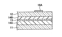
- the glass plate 12 is coated with a conductive film 13.
- the conductive film 13 is sandwiched between the intermediate film 14A and the intermediate film 14B. In the form of FIG. 4B, the conductive film 13 is not offset with respect to the glass plate 12.
- the glass plate 11 is coated with a conductive film 13.
- the conductive film 13 between the glass plate 11 and the dielectric substrate 32 is coated on the glass plate 11.
- the conductive film 13 between the glass plate 11 and the dielectric substrate 32 is bonded to the glass plate 11 with an adhesive 38A.
- the masking film 18 is arranged between the glass plate 12 and the electrode 16. In this embodiment, the masking film 18 is disposed between the glass plate 11 and the conductive film 13.
- FIG. 3B simulation result and experiment result of S11 regarding embodiment of the window glass for vehicles and antenna which concern on this invention.
- FIG. 3C simulation result and experiment result of S11 regarding embodiment
- FIG. 3 is a cross-sectional view of a laminated glass in which a dielectric substrate 48 is attached to a glass plate 12. It is a conceptual diagram of the antenna which added the independent slot 24 (24A, 24B) to the antenna of the form of FIG. 3B. It is a front view (vehicle interior view) of the laminated glass attached to the vehicle body opening. The average antenna gain when the distance L5 is changed is shown. The average antenna gain when the terminal position Ly is changed is shown. It is the figure which moved the electrode 16 to the right, fixing the position of the slot 23. FIG. The ratio band when the area ratio Sr is changed is shown.
- the ratio band when the impedance Zc which changes according to the area of the electrode 16 is changed is shown.
- the average antenna gain when the antenna length H1 is changed is shown.
- the average antenna gain when the antenna width W5 is changed is shown.
- FIG. 18 shows a configuration in which two thin line slots 23B1 and 23B2 are arranged at the same pitch as the antenna width W5 in FIG. 18A.
- FIG. 18A shows a configuration in which four thin line slots 23C1-23C4 are arranged at equal intervals between antenna widths W5.
- a configuration in which the fine line slot 23D1 and the fine line slot 23D2 are connected by a through slot 23D3 is shown.
- the vehicle window glass according to the present invention may be a windshield attached to the front of the vehicle or a side glass attached to a side portion of the vehicle. Moreover, the rear glass attached to a rear part may be sufficient.
- FIG. 2 is an exploded view of the vehicle window glass and antenna according to the present invention.
- the vehicle window glass shown in FIG. 2 is formed by combining a glass plate 11 that is a first glass plate disposed on the vehicle exterior side and a glass plate 12 that is a second glass plate disposed on the vehicle interior side. Laminated glass.
- FIG. 2 shows components of the vehicle window glass and the antenna according to the present invention separated in a normal direction to the surface of the glass plate 11 (or the glass plate 12).
- the conductive film 13 is disposed between the glass plate 11 and the glass plate 12, and the pair of electrodes 16 composed of the electrodes 16 ⁇ / b> A and 16 ⁇ / b> B are formed by It is arrange
- a slot 23 is formed in the conductive film 13. The slot 23 is in contact with the upper edge 13 a of the conductive film 13. That is, one end of the slot 23 is opened at the upper edge 13 a that is the outer peripheral edge of the conductive film 13.
- the glass plate 11, the conductive film 13 in which the slot 23 is formed, the glass plate 12, and the pair of electrodes 16 are laminated in this order to form an antenna.
- the conductive film 13 is arranged in a layer between the glass plate 11 and the glass plate 12, and the glass plate 12 is arranged in a layer between the conductive film 13 and the electrode 16.
- the antenna can be configured by the conductive film, the slot formed in the conductive film, and the pair of electrodes, the fanaticism can be achieved at a predetermined frequency regardless of the slot between the vehicle body flange and the conductive film.
- An intermediate film 14 ⁇ / b> A is disposed between the glass plate 11 and the conductive film 13, and an intermediate film 14 ⁇ / b> B is disposed between the conductive film 13 and the glass plate 12.
- the glass plate 11 and the conductive film 13 are joined by an intermediate film 14A
- the conductive film 13 and the glass plate 12 are joined by an intermediate film 14B.
- the intermediate films 14A and 14B are, for example, thermoplastic polyvinyl butyral.
- the relative dielectric constant ⁇ r of the intermediate films 14A and 14B can be 2.8 or more and 3.0 or less, which is the relative dielectric constant of a general intermediate film of laminated glass.
- the glass plates 11 and 12 are transparent plate-like dielectrics. Further, either one of the glass plates 11 and 12 may be translucent, or both the glass plates 11 and 12 may be translucent.
- An antenna is formed by installing a feeding structure including a glass plate 12 as a dielectric and a pair of electrodes 16 on the conductive film 13 in which the slots 23 are formed.
- the conductive film 13 is a conductive heat ray reflective film that can reflect heat rays coming from the outside.
- the conductive film 13 is transparent or translucent.
- the conductive film 13 illustrated in FIG. 2 is a conductive film formed on the surface of polyethylene terephthalate, but may be a conductive film formed on the surface of a glass plate.
- the conductive film 13 is formed with a slot 23 having the upper edge 13a of the conductive film 13 as an open end.
- the electrode 16 composed of the electrodes 16A and 16B is disposed on the surface on the inner side of the glass plate 12, that is, the surface opposite to the surface facing the conductive film 13.
- the electrode 16 is disposed so as to be exposed on the inner surface of the glass plate 12.
- the slot 23 extends in a direction perpendicular to the longitudinal direction of the slot 23 and parallel to the film surface of the conductive film 13. It is arrange
- the electrode 16B is capacitively coupled to the second coupling portion 22 that is a portion projected onto the conductive film via the glass plate 12 and the intermediate film 14B.
- the first coupling portion 21 is located on one side of the conductive film 13 defined by the slot 23, and the second coupling portion 22 is located on the other side across the slot 23.
- the antenna of this aspect has a laminated structure in which a conductive film 13 is disposed between a glass plate 11 and a glass plate 12, and a pair of electrodes 16 composed of electrodes 16 ⁇ / b> A and 16 ⁇ / b> B sandwich the glass plate 12.
- a slot 23 which is disposed on the opposite side to the position where the conductive film 13 is disposed and one end of which is an open end, is formed in the conductive film 13.
- the first coupling portion 21 that is a projection portion of the electrode 16A onto the conductive film 13 and the second coupling portion 22 that is a projection portion of the electrode 16B onto the conductive film 13 are positioned with the slot 23 interposed therebetween.
- the pair of electrodes is formed such that the electrode 16A and the first coupling portion 21 are separated by a distance capable of capacitive coupling, and the electrode 16B and the second coupling portion 22 are separated by a distance capable of capacitive coupling. 16 is provided.
- the antenna of this aspect has an effect of shortening the antenna by electrostatic coupling between the electrode 16A and the first coupling portion 21 and electrostatic coupling between the electrode 16B and the second coupling portion 22, and a general notch antenna or the like.
- the length of the slot 23 can be made shorter than the required slot length. Therefore, the slot 23 can be made small, and the portion where the conductive film is not formed can be made small.
- the slot 23 is formed with a shape and size suitable for reception of radio waves in a frequency band to be received by the antenna.
- the slot 23, that is, the shape and size of the slot 23 may be set so as to satisfy the required value of the antenna gain necessary for receiving the radio wave in the frequency band that the antenna should receive.
- the slot 23 is formed so as to be suitable for receiving radio waves in the terrestrial digital television broadcast band 470 to 710 MHz.
- the arrangement position of the antenna on the glass is not particularly limited as long as the antenna is suitable for reception of radio waves in a frequency band to be received.
- the antenna of this aspect is disposed in the vicinity of the vehicle body opening end, which is an attachment site of the vehicle window glass. As shown in FIG. 10, it is preferable to arrange in the vicinity of the vehicle body opening end 41 on the roof side in terms of improving the antenna gain. Further, it may be arranged at a position moved to the right or left from the position shown in FIG. 10 so as to approach the vehicle body opening end 42 or 44 on the pillar side. Further, it may be disposed in the vicinity of the chassis-side vehicle body opening end 43. In the case of FIG. 10, the longitudinal direction of the slot 23 coincides with the direction orthogonal to the side of the vehicle body opening end 41 or 43.
- the antenna of this embodiment has a laminated structure in which a conductive film 13 is disposed between a glass plate 11 and a glass plate 12, and includes a signal line side electrode 16A, a ground line side electrode 16B, A first coupling portion 21 electrostatically coupled to the electrode 16A via the glass plate 12, a second coupling portion 22 electrostatically coupled to the electrode 16B via the glass plate 12, and a first coupling portion 21. And a slot 23 sandwiched between the second coupling portions 22.
- the electrode 16A may be an electrode on the ground line side
- the electrode 16B may be an electrode on the signal line side.
- the electrode 16A is connected to a signal line connected to a signal processing device (for example, an amplifier) mounted on the vehicle body side so as to be conductive.
- a signal processing device for example, an amplifier
- the electrode 16B is connected to a ground line connected to a ground part on the vehicle body side so as to be conductive.
- Examples of the ground part on the vehicle body side include a body ground and a ground of a signal processing device to which a signal line connected to the electrode 16A is connected.
- the reception signal of the radio wave received by the antenna is transmitted to a signal processing device mounted on the vehicle via a conductive member connected to the pair of electrodes 16 so as to be energized.
- a conductive member a power supply line such as an AV line or a coaxial cable may be used.
- the electrodes 16A and 16B are formed by printing and baking a paste containing a conductive metal, such as a silver paste, on the inner surface of the window glass plate 12.
- a paste containing a conductive metal such as a silver paste
- the present invention is not limited to this forming method, and a linear body or a foil-like body made of a conductive material such as copper may be formed on the inner surface of the glass plate 12, and the glass plate 12 may be coated with an adhesive or the like. It may be affixed.
- the shape of the electrodes 16A and 16B and the interval between the electrodes may be determined in consideration of the shape of the mounting surface of the conductive member or connector and the interval between the mounting surfaces.
- a square shape or a polygonal shape such as a square, a substantially square, a rectangle, or a substantially rectangle is preferable for mounting. It may be a circle such as a circle, a substantially circle, an ellipse, or a substantially ellipse.
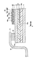
- FIG. 8 is a cross-sectional view of a laminated glass in which the dielectric substrate 48 is attached to the glass plate 12.
- An example of the dielectric substrate 48 is a glass epoxy substrate having FR4 as a base material, but substrates of other materials may be used as long as the impedance is adjusted.
- the dielectric substrate 48 is attached to the surface of the glass plate 12 with, for example, an acrylic foam tape 47.
- the electrode 49 includes an upper electrode 49A formed on the upper surface of the dielectric substrate 48 and a lower electrode 49B formed on the lower surface of the dielectric substrate 48.
- the upper electrode 49A and the lower electrode 49B are electrically connected through a plurality of through holes 48a.
- Two electrodes 49 are provided on the dielectric substrate 48, and the electrodes 16 corresponding to the electrodes 16A and 16B shown in FIG. 2 and the like are formed.
- the connector can be mounted on the glass plate by simply attaching the dielectric substrate 48 to the glass plate 12 by attaching the above-described connector to the upper electrode 49A in advance. This can simplify the work.
- the laminated glass when attached to the vehicle body opening end 41 or the like, it is attached to the flange portion of the vehicle body frame 45 by an adhesive 46 (or packing).
- FIG. 3A is a front view of the vehicle window glass 100 according to the first embodiment of the present invention.
- FIG. 3A is a view when the surface of the glass plate 12 disposed on the vehicle inner side is viewed from the vehicle inner side.
- FIG. 3A is an overall view of the vehicle window glass 100.
- the antenna 20 is arranged on the upper right side of the vehicle window glass 100.
- FIG. 3B is an enlarged view of an arrangement place of the antenna 20.
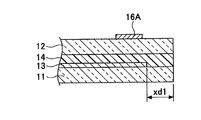
- edges (13a to 13d) of the conductive film 13 are offset from the edges (12a to 12d) of the glass plate 12 by a distance xd1. By providing such an offset, it is possible to prevent the conductive film 13 from being corroded by water or the like from the mating surfaces of the glass plates 11 and 12.
- an independent slot 24 not connected to the slot 23 may be formed close to the slot 23 and closed in the conductive film 13 without contacting the outer peripheral edge of the conductive film 13. . Further, the independent slot may be formed with one end as an open end in the same manner as the slot 23. By providing the independent slot 24, it is possible to increase the bandwidth of the antenna 20 compared to the case where the independent slot 24 is not provided.
- FIGS. 4A-4F are cross-sectional views of the vehicle window glass 100 along AA shown in FIG. 3A.
- 4A to 4F show variations of the laminated form of the vehicle window glass and the notch antenna according to the present invention.
- FIGS. 4A to 4F show a form having a laminated structure in which the glass plate 11 and the conductive film 13 are disposed between the glass plate 11 and a dielectric (that is, the glass plate 12 or the dielectric substrate 32).
- the electrode 16 is disposed on the opposite side of the conductive film 13 with the dielectric in between.
- the conductive film 13 is in contact with the adhesive layer between the glass plate and the dielectric.
- FIG. 4A shows a form in which the conductive film 13 is coated on the glass plate 12 by performing a vapor deposition process on the opposite surface of the glass plate 12 facing the glass plate 11.
- 4B shows a film-like structure between the intermediate film 14A in contact with the facing surface of the glass plate 11 facing the glass plate 12 and the intermediate film 14B in contact with the facing surface of the glass plate 12 facing the glass plate 11.
- the conductive film 13 is sandwiched.
- the film-like conductive film 13 may have a form in which the conductive film 13 is coated by depositing the conductive film 13 on the film.
- FIG. 4C is a form in which the conductive film 13 is not offset with respect to the glass plate 12 in the form of FIG. 4B.
- FIG. 4D shows a form in which the conductive film 13 is coated on the glass plate 11 by vapor-depositing the conductive film 13 on the facing surface of the window glass 11 facing the window glass 12.
- the vehicle window glass according to the present invention may not be laminated glass.
- the conductive film 13 is disposed between the glass plate 11 and the dielectric substrate 32.
- FIG. 4E shows a form in which the conductive film 13 is coated on the glass plate 11 by vapor-depositing the conductive film 13 on the opposite surface of the glass plate 11 facing the dielectric substrate 32.
- the conductor film 13 and the dielectric substrate 32 are bonded by an adhesive 38.
- FIG. 4F shows a form in which the conductive film 13 is bonded to the opposing surface of the glass plate 11 facing the dielectric substrate 32 with an adhesive 38A.
- the conductor film 13 and the dielectric substrate 32 are bonded by an adhesive 38B.
- the dielectric substrate 32 is a resin substrate made of resin, and is provided with a pair of electrodes.
- the resin substrate may be a printed substrate on which a pair of electrodes are printed.
- FIG. 5A is a front view and a BB sectional view of a vehicle window glass 200 according to a second embodiment of the present invention.
- FIG. 5A is a front view when the surface of the glass plate 12 disposed on the vehicle inner side is viewed from the vehicle inner side. The description of the same parts as in FIG. 3A will be omitted or simplified.
- the surface of the glass plate is interposed between the pair of electrodes 16 and the glass plate 11 (on the back side in FIG. 5A).
- a masking film 18 to be formed may be provided.
- the masking film 18 may be a ceramic that is a fired body such as a black ceramic film. In this case, when viewed from the outside of the window glass, the portions of the electrodes 16A and 16B provided on the masking film 18 by the masking film 18 become invisible from the outside of the vehicle, and the window glass has an excellent design.
- 5B and 5C are cross-sectional views of the vehicle window glass 100 taken along BB shown in FIG. 5A.
- 5B and 5C show variations of the laminated form of the vehicle window glass and the antenna according to the present invention.
- 5B and 5C show a form having a laminated structure in which the glass plate 11 and the conductive film 13 are disposed between the glass plate 11 and a dielectric (that is, the glass plate 12), and the pair of electrodes 16 has a dielectric structure. It shows what is disposed on the opposite side of the conductive film 13 across the body.
- FIG. 5B shows a form in which the conductive film 13 is coated on the glass plate 11 by subjecting the conductive film 13 to the opposite surface of the glass plate 11 facing the glass plate 12 by vapor deposition.
- a shielding film 18 formed on the glass plate 12 is disposed between the glass plate 12 and the electrode 16.
- FIG. 5C shows a form in which the conductive film 13 is coated on the glass plate 12 by performing a vapor deposition process on the opposing surface of the glass plate 12 facing the glass plate 11.
- a concealment film 18 formed on the glass plate 11 is disposed between the glass plate 11 and the conductor film 13.
- the masking film 18 is formed in the inner region at a distance xd3 from the outer edge of the glass plate 12.
- the distance xd1 (or xd2) between the outer edge of the glass plate 12 and the conductive film 13 shorter than the distance xd3, the outer peripheral edge of the conductive film 13 can be hidden by the masking film 18, and the outer peripheral edge of the conductive film becomes conspicuous. Loss of design is improved. Further, the heat rays can be shielded between the conductive film 13 and the masking film 18 without a gap.
- the mounting angle of the window glass with respect to the vehicle is preferably 15 to 90 °, particularly 30 to 90 ° with respect to the horizontal plane (horizontal plane).
- the experiment was conducted assuming that a glass substrate with a square of 300 mm in length and width of 3.1 mm was used as the window glass.
- the size of the electrode is a square of 15 mm in length and width.
- the size of the copper foil is 250 mm long and 300 mm wide.
- the offset distance from the edge of the glass substrate assumed to be the roof side edge to the edge of the copper foil was set to 50 mm.
- the slot was formed in the copper foil so that one end of the slot of the antenna was opened at the edge of the copper foil on the roof side. Assume that there is no car body or defogger.
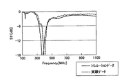
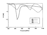
- the return loss characteristic (reflection characteristic) S11 was measured for each 5 Hz at a frequency of 100 to 1100 MHz for the antenna actually manufactured in this manner and the numerically calculated antenna having the same dimensions. In addition, measurements were performed on the notch antennas of the respective forms of FIGS. 3B and 3C. In the case of numerical calculation, numerical calculation was performed by electromagnetic field simulation based on the FDTD method (Finite-Difference Time-Domain method), and the return loss characteristic (reflection coefficient) S11 was calculated. In S11, the closer to zero, the larger the return loss and the smaller the antenna gain, and the larger the negative value, the smaller the return loss and the larger the antenna gain.
- FDTD method Finite-Difference Time-Domain method
- the dimensions at the time of measurement in S11 are as follows: the length in the longitudinal direction of the slot 23 is 83 mm, and the width of the slot 23 is 3 mm.
- the measurement dimensions of S11 are the same as the length and width of the slot 23 in the longitudinal direction as in the form of FIG. 3B.
- the length of the independent slot 24 in the longitudinal direction parallel to the longitudinal direction of the slot 23 is 165 mm, and the width of the independent slot 24 is 3 mm.
- the separation distance in the direction orthogonal to the longitudinal direction of the slot 23 and the independent slot 24 is 10 mm.
- the shortest distance between the copper foil roof side edge and the independent slot 24 is 41.5 mm.
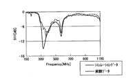
- 6A and 6B show the simulation results and experimental results of S11 in FIGS. 3B and 3C.
- 6A shows the result in the case of FIG. 3B
- FIG. 6B shows the result in the case of FIG. 3C
- the solid line shows the calculated value on the simulation
- the dotted line shows the experimental value.
- the antenna of FIG. 3B has a resonance point in the vicinity of 350 to 400 MHz, and it can be seen that the conductive film functions as an antenna.
- two resonance points are generated in the vicinity of 300 to 350 MHz and in the vicinity of 550 to 600 MHz, so that the bandwidth is increased as compared with the case where there is no independent slot. be able to.
- FIG. 7 shows the antenna of FIG. 3B (Example 1), the notch antenna (Example 2) that feeds power directly to the slot without electrostatic coupling in the conductive film having the same slot shape as FIG. 3B, and no electrostatic coupling.
- Fig. 6 shows a result of comparison between a notch antenna (Example 3) in which the length of the slot is adjusted to 275 mm so as to resonate in the vicinity of 350 to 400 MHz in the notch antenna that feeds power directly to the slot.
- the slot of the antenna of FIG. 3B can be formed short. Also, by configuring the feeding structure with electrostatic coupling, the return loss can be reduced at the resonance point compared to a notch antenna that feeds power directly to the slot without electrostatic coupling, so that the antenna gain can be improved.
- an antenna using a conductive film can be configured without using a slot between the vehicle body flange and the conductive film. Therefore, since the vehicle body flange is not used, the installation accuracy of the glass plate on the vehicle body flange is not required.
- the slot length can be shortened compared with the case where the conductive film is provided with a slot and power is directly supplied, and the region without the conductive film can be reduced. Further, since it is not necessary to make a hole in the glass plate and it is not necessary to provide a power supply conductor that bypasses the outer periphery of the glass plate, an antenna using a conductive film can be realized with a simple configuration.
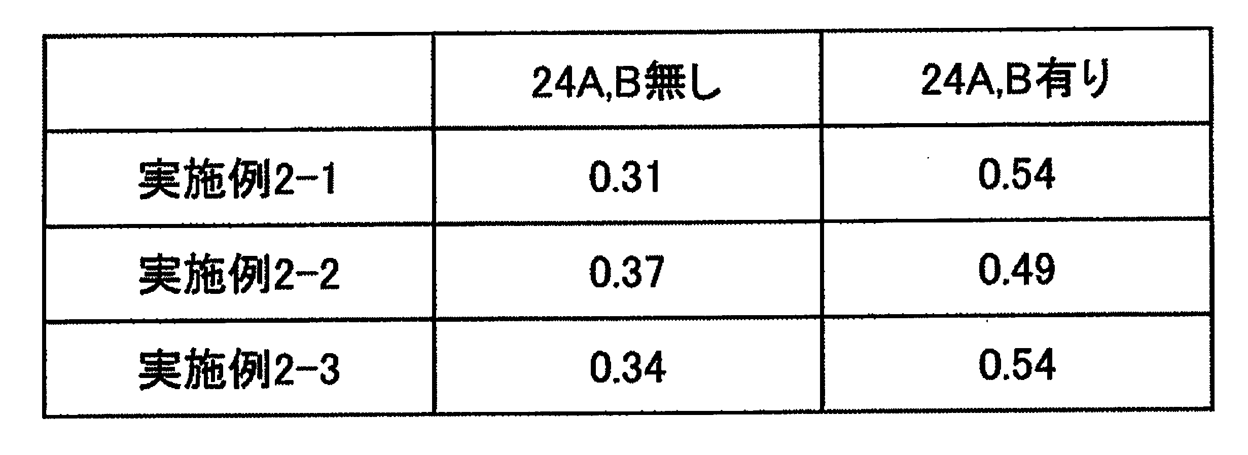
- Example 2 the effect of widening the antenna of the present invention by adding an independent slot will be described.
- FIG. 9 is a typical view of an antenna in which independent slots 24 (24A, 24B) are added to the antenna of the form of FIG. 3B.
- the independent slots 24A and 24B are parasitic slots formed with one end as an open end. The open ends of the independent slots 24A and 24B are in contact with the upper edge 13a of the conductive film 13 with which the open ends of the slots 23 are in contact.
- the independent slot 24 ⁇ / b> A is formed so that the electrode 16 ⁇ / b> A is positioned between the independent slot 24 ⁇ / b> A and the independent slot 24 ⁇ / b> B is formed such that the electrode 16 ⁇ / b> B is positioned between the independent slot 24 ⁇ / b> B and the slot 23.
- Example 2 the numerical calculation based on the FDTD method was performed every 0.6 MHz at a frequency of 200 to 500 MHz, assuming the antenna of the form of FIG. 9 in which the conductive film 13 was provided on the inner layer of the laminated glass.
- the glass size of the laminated glass is changed, numerical calculation was performed for three different glass sizes with different W1, W2, H7, and H10.
- the body frame which is the attachment part of the laminated glass on which the antenna is formed, is modeled as the conductor 50, and the boundary conditions around the glass are infinite.
- the layer structure of FIG. 9 is the form of FIG. 4B.
- the conductor 50 is formed in the same layer as the electrodes 16A and 16B.
- the dimensions (unit: mm) and constants of each part in FIGS. 3B and 9 are as follows.
- Example 2-1 first glass size] H1: 70 H2, H3: 170 H4, H5: 10 H6: 376 H7: 356 H8: 90 H9: 40 H10: 506 H11: 50 W1: 960 W2: 880 W3: 10 W4, W5, W6: 3 W7. W8: 40 W9, W10: 100 W40: 5 W41, H42, W43, H44: 20
- Example 2-2 Second glass size (only the changed part from Example 2-1 is displayed)] H7: 470 H10: 620 W1: 1200 W2: 1100
- Example 2-3 Third glass size (displays only the changed part from Example 2-1)] H7: 604 H10: 734 W1: 1440 W2: 1360
- Thickness of the glass plates 11 and 12 2.0 Dielectric constant of glass plates 11 and 12: 7.0
- the thickness of the intermediate films 14A and 14B 0.381 Sheet resistance of the conductive film 13: 2.0 [ ⁇ / ⁇ (ohm / square)]
- the thickness of the conductive film 13 0.01
- Thickness of conductor 50 and electrodes 16A and 16B 0.01
- F w Bandwidth of VSWR ⁇ 3.0
- F H Maximum value of frequency of VSWR ⁇ 3.0
- F L Expressed by minimum value of frequency of VSWR ⁇ 3.0.
- the addition of the independent slots 24A and 24B increases the value of the ratio band. That is, by adding an independent slot, it is possible to increase the bandwidth of the antenna.
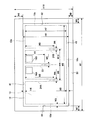
- FIG. 10 is a front view (in-vehicle view) of the laminated glass on which the antenna of the form of FIG. 3B is formed.
- FIG. 10 shows a state in which the laminated glass is attached to the vehicle body opening.
- Example 3 the distance L7 between the vehicle body opening end 41 on the roof side and the upper edge 13a of the conductive film 13 is set for a planar antenna of the form shown in FIG. 10 actually manufactured using laminated glass for an automobile windshield.
- the antenna gain when changing was measured using a real vehicle.
- the antenna gain was measured by assembling an automobile window glass with a glass antenna formed on an automobile window frame on a turntable.
- the antenna part of the window glass for automobiles was in a state inclined about 16 ° with respect to the horizontal plane.
- a connector connected to the coaxial cable was attached to the power feeding section (adopting the power feeding structure of FIG. 8).
- the antenna gain was measured by setting the vehicle center of an automobile in which a window glass for an automobile on which a glass antenna was formed was set at the center of the turntable, and rotating the automobile 360 °.
- the antenna gain data was measured every 5 MHz at 250 to 450 MHz for each rotation angle of 1 ° in two cases of horizontal polarization and vertical polarization.
- the antenna gain was standardized so that the half-wave dipole antenna was 0 dB with reference to the half-wave dipole antenna.
- the layer configuration of FIG. 10 is the form of FIG. 4B.
- the dimensions and constants of each part in Example 2 are the same as in Example 2 except for the outer dimensions of the laminated glass.
- Table 2 shows the arithmetic average value (unit: dBd) of the measured data of the antenna gain for the entire 360 ° circumference at the representative frequency of 330 MHz when the distance L7 is changed. As shown in Table 2, even if the distance L7 is changed, the antenna gain does not change greatly. That is, since the upper edge 13a of the conductive film 13 can be brought closer to the vehicle body opening end 41, the slot 23 can be brought closer to the upper edge 12a of the window glass, so that the visibility of the window glass is improved.
- Example 4 a change in antenna gain due to a difference in installation position in the left-right direction of the entire antenna of the present invention will be described.
- FIG. 11 shows an arithmetic average value (unit: dBd) of measured data of antenna gain for the entire 360 ° circumference at 330 MHz when the distance L5 normalized with the wavelength ⁇ 0 of the representative frequency 330 MHz is changed.
- the length to the center line between the left edge 13d and right edge 13b of the conductive film 13 as the maximum value, the distance L5 is 0.1 [lambda] 0 or more, more preferably 0.4Ramuda 0 or more This is advantageous in terms of improving the antenna gain.
- Example 5 a change in antenna gain due to a difference in position in the vertical direction of the electrode 16 (16A, 16B) of the antenna of the present invention will be described.
- Example 5 the antenna gain when the distance L7 was set to 15 mm and the terminal position Ly of the electrode 16 was changed in the vertical direction was measured using a real vehicle for the planar antenna of the same form as in Example 3 in FIG. .
- the dimensions and constants of each part and the antenna gain measurement conditions in Example 5 are the same as in Example 3.
- FIG. 12 shows the arithmetic average value (unit: dBd) of the measured data of the antenna gain for the entire 360 ° circumference at the representative frequency of 330 MHz when the terminal position Ly is changed.
- dBd arithmetic average value
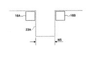
- Example 6 describes a change in antenna gain due to a difference in position in the left-right direction of the electrode 16 (16A, 16B) of the antenna of the present invention.
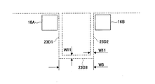
- Example 6 assuming the antenna in the form of FIG. 3B in which the conductive film 13 is provided on the inner layer of a square laminated glass, numerical calculation based on the FDTD method was performed every 0.6 MHz at a frequency of 250 to 450 MHz. . Further, as shown in FIG. 13, the electrode 16 (16A, 16B) moves to the right as a whole as shown in FIG. 13 while the shortest distance W40 (see FIG. 3B) between the electrodes 16A and 16B is fixed to 10 mm. An assumed numerical calculation was performed. In this numerical calculation, it was modeled that there was no body frame that was the attachment part of the laminated glass on which the antenna was formed, and the boundary conditions around the glass were finite (the surrounding was free space).
- the shape of the laminated glass assumed in Example 6 was a square of 300 mm in length and width. The position of the center line of the slot 23 was on the bisector of one side of the square laminated glass.
- the layer configuration assumed in Example 6 was the layer configuration of the laminated glass and the feeding structure shown in FIG. The dimensions (unit: mm) and constants of each part in Example 6 are shown below with reference to the symbols in FIGS. 3A and 3B.
- Thickness of the dielectric substrate 48 0.4 Dielectric constant of dielectric substrate 48: 4.0 Acrylic foam tape 47 thickness: 0.4 Relative permittivity of acrylic foam tape 47: 3.0 Electrode 49A thickness: 0.01 H1: 70 H21: 300 H23: 30 H24: 10 W5: 3 W21: 300 W23, W24: 10 W40: 10 W41, H42, W43, H44: 20
- the area ratio Sr is 0.5 or more, more preferably 0.6 or more, it is advantageous in terms of widening the antenna band. That is, if the electrodes 16A and 16B are arranged on both sides of the slot 23 without overlapping the slot 23, it is advantageous in terms of widening the antenna.
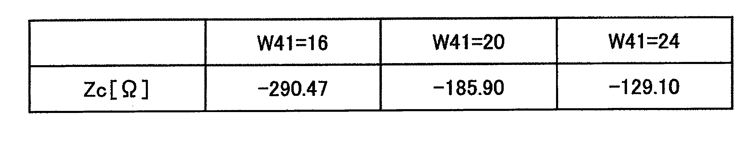
- Example 7 describes the change in antenna gain due to the difference in size (area) of the electrodes 16 (16A, 16B) of the antenna of the present invention.
- Example 7 assuming the same antenna as in Example 6 in the form of FIG. 3B, numerical calculation based on the FDTD method was performed every 0.6 MHz at a frequency of 250 to 450 MHz. In addition, numerical calculation based on the FDTD method was performed for two cases where the width W5 of the slot 23 was 3.0 mm and 7.5 mm while the shape of each of the electrodes 16 was kept square. The dimensions and constants of each part in Example 7 are the same as in Example 6.
- the ratio band on the vertical axis in FIG. 15 is a value calculated according to the above-described calculation formula (1).
- ⁇ 400 ⁇ Zc ⁇ ⁇ 80, more preferably ⁇ 300 ⁇ Zc ⁇ ⁇ 100, is advantageous in terms of widening the antenna.
- Example 8 describes changes in antenna gain due to differences in size (area) of the electrodes (16A, 16B) of the antenna of the present invention.
- Example 8 with respect to the planar antenna of the same form of FIG. 10 as Example 3, the antenna length H1 of the slot 23 is fixed to 70 mm and the shape of each of the electrodes 16 is kept square, and one side of each square electrode 16 is maintained.
- the antenna gain when the length W41 and the shortest distance W40 between the electrodes 16A and 16B were changed was measured using an actual vehicle.
- the dimensions and constants of each part and the antenna gain measurement conditions in Example 8 are the same as in Example 3.
- the antenna gain in Example 8 was measured by actually manufacturing the feed structure of FIG.
- Table 3 shows an arithmetic average value (unit: average value) of actual measurement data of the antenna gain for the entire circumference of 360 ° at the representative frequency of 330 MHz when the shortest interval W40 and the length of one side W41 are changed in the case of horizontal polarization.
- dBd shows the arithmetic average value (unit: dBd) of the measured data of the antenna gain for the entire 360 ° circumference at 330 MHz when the shortest interval W40 and the side length W41 are changed in the case of vertical polarization.
- Table 5 shows Zc when the length W41 of one side is 16, 20, and 24 mm. As shown in Tables 3, 4, and 5, when the area of the electrode 16 is changed, Zc changes, and adjustment to a value close to the peak value of the graph shown in FIG. 15 is advantageous in that the antenna gain is improved. is there.
- Example 9 the antenna gain when the antenna length H1 of the slot 23 was changed was measured for the planar antenna of the form of FIG. 3B actually manufactured using a square laminated glass.
- the dimensions and constants of each part in Example 9 are the same as in Example 6.
- the measurement conditions of the antenna gain are the same as those in Example 3 except that the measurement was performed by placing a square laminated glass on which the antenna of the form of FIG. 3B was formed vertically on a foamed polystyrene table.
- FIG. 16 shows an arithmetic average value (unit: dBd) of measured data of antenna gain for the entire 360 ° circumference at a representative frequency of 380 MHz when the antenna length H1 is changed.
- dBd arithmetic average value
- Example 10 the antenna gain when the antenna width W5 of the slot 23 was changed was measured for the planar antenna in the form of FIG.
- the dimensions and constants of each part in Example 10 are the same as in Example 6.
- the antenna gain measurement conditions are the same as in the ninth embodiment.
- FIG. 17 shows the arithmetic average value (unit: dBd) of the measured data of the antenna gain for the entire 360 ° circumference at the representative frequency of 380 MHz when the antenna width W5 is changed.
- the antenna width W5 is 1 mm or more and 10 mm or less, more preferably 2 mm or more and 9 mm or less, it is advantageous in terms of improving the antenna gain.
- Example 11 the antenna gain of a planar antenna in the form of FIGS. 18A-18D actually manufactured using a square laminated glass was measured.
- a variation of the slot 23 composed of a plurality of thin line slots is shown.
- the slot width of the plurality of thin line slots is W11.
- FIG. 18A shows the same slot configuration as in FIG. 3B in which the antenna width W5 of the slot 23A is exaggerated.
- FIG. 18B shows a slot configuration in which two thin line slots 23B1 and 23B2 are arranged at the same pitch as the antenna width W5 of FIG. 18A.
- FIG. 18C shows a slot configuration in which four thin line slots 23C1-23C4 are arranged at equal intervals between the antenna width W5 of FIG.
- FIG. 18D shows a U-shaped slot configuration in which the fine slot 23D1 and the through slot 23D3 penetrating the fine slot 23D2 are connected.
- the dimensions and constants of each part in Example 11 are the same as in Example 6 except for the antenna width W5.
- the antenna gain measurement conditions are the same as in the ninth embodiment.
- Table 6 shows the arithmetic mean value (unit: dB) of the measured data of the antenna gain for the entire 360 ° circumference at the representative frequency of 380 MHz when the width W11 and the number of the thin wire slots are changed. The value expressed as a relative difference from the arithmetic mean value is shown.
- the slot width W11 of the thin line can be narrowed while ensuring the antenna gain. Therefore, in order to obtain the antenna width W5 necessary for improving the antenna gain shown in the tenth embodiment (FIG. 17), it is possible to obtain the same characteristics by providing a plurality of thin line slots having a narrow width W11.
- the passenger can be made inconspicuous as compared with the case where the thick slot 23 is provided, and the design is improved, and the fine wire slot can be easily formed by laser processing, so that the productivity is improved. .
- the present invention is used for, for example, a glass antenna for an automobile that receives terrestrial digital TV broadcast, UHF analog TV broadcast, US digital TV broadcast, European Union digital TV broadcast, or People's Republic of China digital TV broadcast. It is preferable. Also used in Japan FM broadcast band (76-90 MHz), US FM broadcast band (88-108 MHz), TV VHF band (90-108 MHz, 170-222 MHz), vehicle keyless entry system (300-450 MHz) it can.
- 800 MHz band for car phones (810 to 960 MHz), 1.5 GHz band for car phones (1.429 to 1.501 GHz), GPS (Global Positioning System), GPS signal of artificial satellites 1575.42 MHz), VICS (Registered trademark) (Vehicle Information and Communication System: 2.5 GHz).
- ETC communication Electronic Toll Collection System: non-stop automatic toll collection system, roadside wireless device transmission frequency: 5.795 GHz or 5.805 GHz, roadside wireless device reception frequency: 5.835 GHz or 5.845 GHz), dedicated narrow Area communication (DSRC: Dedicated Short Range Communication, 915 MHz band, 5.8 GHz band, 60 GHz band), microwave (1 GHz to 3 THz), millimeter wave (30 to 300 GHz), and SDARS (Satellite Digital Audio Radio Service IV (2. 34 GHz, 2.6 GHz)).
- DSRC Dedicated Short Range Communication
Landscapes
- Details Of Aerials (AREA)
- Waveguide Aerials (AREA)
Abstract
Description
ガラス板と、該ガラス板に積層された導電膜と、該導電膜に給電構造を設置して構成されたアンテナとを有する車両用窓ガラスであって、
前記給電構造は、誘電体と一対の電極とを有し、
前記導電膜は、一端が該導電膜の端部を開放端とするスロットを有し、かつ前記ガラス板と前記誘電体との間に配置され、
前記一対の電極は、前記誘電体を挟んだ前記導電膜側の反対側に、かつ該一対の電極を前記導電膜に投影すると前記スロットを一対の電極で挟むように配置され、前記導電膜と容量的に結合されることを特徴とするものである。 In order to achieve the above object, a vehicle window glass according to the present invention comprises:
A vehicle window glass having a glass plate, a conductive film laminated on the glass plate, and an antenna configured by installing a feeding structure on the conductive film,
The power feeding structure has a dielectric and a pair of electrodes,
The conductive film has a slot whose one end is an end of the conductive film, and is disposed between the glass plate and the dielectric,
The pair of electrodes is disposed on the opposite side of the conductive film with the dielectric interposed therebetween, and is disposed so that the slot is sandwiched between the pair of electrodes when the pair of electrodes is projected onto the conductive film. It is characterized by being capacitively coupled.
ガラス板と、該ガラス板に積層された導電膜と、該導電膜に設けられた給電構造とを有するアンテナであって、
前記給電構造は、誘電体と一対の電極とを有し、
前記導電膜は、一端が該導電膜の端部を開放端とするスロットを有し、かつ前記ガラス板と前記誘電体との間に配置され、
前記一対の電極は、前記誘電体を挟んで前記導電膜側の反対側、かつ該一対の電極を前記導電膜に投影すると前記スロットを一対の電極で挟むように配置され、前記導電膜と容量的に結合されることを特徴とするものである。 In order to achieve the above object, the antenna according to the present invention is
An antenna having a glass plate, a conductive film laminated on the glass plate, and a feeding structure provided on the conductive film,
The power feeding structure has a dielectric and a pair of electrodes,
The conductive film has a slot whose one end is an end of the conductive film, and is disposed between the glass plate and the dielectric,
The pair of electrodes is disposed on the opposite side of the conductive film with the dielectric interposed therebetween, and is disposed so that the slot is sandwiched between the pair of electrodes when the pair of electrodes is projected onto the conductive film. It is characterized by being connected to each other.
このように、導電膜と導電膜に形成されたスロットと一対の電極とでアンテナを構成できるため、車体フランジと導電膜との間のスロットに関係なく所定の周波数で狂信させることができる。 FIG. 2 is an exploded view of the vehicle window glass and antenna according to the present invention. The vehicle window glass shown in FIG. 2 is formed by combining a
Thus, since the antenna can be configured by the conductive film, the slot formed in the conductive film, and the pair of electrodes, the fanaticism can be achieved at a predetermined frequency regardless of the slot between the vehicle body flange and the conductive film.
H1:70
H2,H3:170
H4,H5:10
H6:376
H7:356
H8:90
H9:40
H10:506
H11:50
W1:960
W2:880
W3:10
W4,W5,W6:3
W7.W8:40
W9,W10:100
W40:5
W41,H42,W43,H44:20 [Example 2-1: first glass size]
H1: 70
H2, H3: 170
H4, H5: 10
H6: 376
H7: 356
H8: 90
H9: 40
H10: 506
H11: 50
W1: 960
W2: 880
W3: 10
W4, W5, W6: 3
W7. W8: 40
W9, W10: 100
W40: 5
W41, H42, W43, H44: 20
H7:470
H10:620
W1:1200
W2:1100 [Example 2-2: Second glass size (only the changed part from Example 2-1 is displayed)]
H7: 470
H10: 620
W1: 1200
W2: 1100
H7:604
H10:734
W1:1440
W2:1360 [Example 2-3: Third glass size (displays only the changed part from Example 2-1)]
H7: 604
H10: 734
W1: 1440
W2: 1360
ガラス板11,12の厚さ:2.0
ガラス板11,12の比誘電率:7.0
中間膜14A,14Bの厚さ:0.381
導電膜13のシート抵抗:2.0[Ω/□(ohm/square)]
導電膜13の厚さ:0.01
導体50及び電極16A,16Bの厚さ:0.01 [Dimensions and constants common to Examples 2-1, 2-2, and 2-3]
Thickness of the
Dielectric constant of
The thickness of the
Sheet resistance of the conductive film 13: 2.0 [Ω / □ (ohm / square)]
The thickness of the conductive film 13: 0.01
Thickness of
比帯域=Fw/{(FH-FL)/2} ・・・(1)
Fw:VSWR<3.0の帯域幅
FH:VSWR<3.0の周波数の最大値
FL:VSWR<3.0の周波数の最小値
で表される。 Table 1 shows the result of numerical calculation of a fractional bandwidth of VSWR (Voltage Standing Wave Ratio) = 3.0 or less in a frequency range of 200 to 500 MHz. The ratio band in Table 1 is calculated by the following formula: Ratio band = F w / {(F H −F L ) / 2} (1)
F w : Bandwidth of VSWR <3.0 F H : Maximum value of frequency of VSWR <3.0 F L : Expressed by minimum value of frequency of VSWR <3.0.

Ly=(H11+H44(又は、H42))/H1 ・・・(2)
H11+H44(又は、H42):スロット23の下端と電極16の上端との距離
H1:スロット23のスロット長(アンテナ長)
で表される。 The terminal position Ly is calculated using the expression Ly = (H11 + H44 (or H42)) / H1 (2) with reference to the sign of FIG. 3B.
H11 + H44 (or H42): distance between the lower end of the
It is represented by
誘電体基板48の厚さ:0.4
誘電体基板48の比誘電率:4.0
アクリルフォームテープ47の厚さ:0.4
アクリルフォームテープ47の比誘電率:3.0
電極49Aの厚さ:0.01
H1:70
H21:300
H23:30
H24:10
W5:3
W21:300
W23,W24:10
W40:10
W41,H42,W43,H44:20 The shape of the laminated glass assumed in Example 6 was a square of 300 mm in length and width. The position of the center line of the
Thickness of the dielectric substrate 48: 0.4
Dielectric constant of dielectric substrate 48: 4.0
Relative permittivity of acrylic foam tape 47: 3.0
H1: 70
H21: 300
H23: 30
H24: 10
W5: 3
W21: 300
W23, W24: 10
W40: 10
W41, H42, W43, H44: 20
Sr=領域16Alの面積/(領域16Alの面積+領域16Arの面積)
・・・(3)
で表される。図14の縦軸の比帯域は、上述の演算式(1)に従って演算された値である。図14に示されるように、面積比Srが0.5以上、より好ましくは0.6以上であると、アンテナの広帯域化の点で有利である。すなわち、電極16A,16Bがスロット23に重複せずにスロット23の両側に配置されると、アンテナの広帯域化の点で有利である。 FIG. 14 shows the result of numerical calculation of the ratio band of VSWR = 3.0 or less in the frequency range of 250 to 450 MHz when the area ratio Sr is changed. As shown in FIG. 13, when the left region of the
... (3)
It is represented by The ratio band on the vertical axis in FIG. 14 is a value calculated according to the above-described calculation formula (1). As shown in FIG. 14, when the area ratio Sr is 0.5 or more, more preferably 0.6 or more, it is advantageous in terms of widening the antenna band. That is, if the


本出願は、2009年7月9日出願の日本特許出願(特願2009-163099)に基づくものであり、その内容はここに参照として取り込まれる。 Although this application has been described in detail and with reference to specific embodiments, it will be apparent to those skilled in the art that various changes and modifications can be made without departing from the spirit and scope of the invention.
This application is based on a Japanese patent application (Japanese Patent Application No. 2009-163099) filed on Jul. 9, 2009, the contents of which are incorporated herein by reference.
3 導電膜
4 中間膜
5 アンテナ導体
6 電極
7 導体
11 車外側ガラス板
12 車内側ガラス板
12a~12d 外縁
13 熱反射膜(導電膜)
13a~13d 外縁
14 中間膜
16A,16B 電極
18 隠蔽膜
20 アンテナ
21 第1の結合部
22 第2の結合部
23 スロット
24,24A,24B 独立スロット
32 誘電体基板
38,38A,38B 接着剤(接着層)
41 ルーフ側車体開口端
42,44 ピラー側車体開口端
43 シャーシー側車体開口端
45 車体フレーム
46 接着剤
47 アクリルフォームテープ
48 誘電体基板
48a スルーホール
49 電極
49A 上側電極
49B 下側電極
50 導体 DESCRIPTION OF
13a to
41 Roof side
Claims (15)
- ガラス板と、該ガラス板に積層された導電膜と、該導電膜に給電構造を設置して構成されたアンテナとを有する車両用窓ガラスであって、
前記給電構造は、誘電体と一対の電極とを有し、
前記導電膜は、一端が該導電膜の端部を開放端とするスロットを有し、かつ前記ガラス板と前記誘電体との間に配置され、
前記一対の電極は、前記誘電体を挟んだ前記導電膜側の反対側に、かつ該一対の電極を前記導電膜に投影すると前記スロットを一対の電極で挟むように配置され、前記導電膜と容量的に結合されることを特徴とする車両用窓ガラス。 A vehicle window glass having a glass plate, a conductive film laminated on the glass plate, and an antenna configured by installing a feeding structure on the conductive film,
The power feeding structure has a dielectric and a pair of electrodes,
The conductive film has a slot whose one end is an end of the conductive film, and is disposed between the glass plate and the dielectric,
The pair of electrodes is disposed on the opposite side of the conductive film with the dielectric interposed therebetween, and is disposed so that the slot is sandwiched between the pair of electrodes when the pair of electrodes is projected onto the conductive film. A window glass for a vehicle, which is capacitively coupled. - 前記導電膜は、前記スロットに近接した独立スロットを有する、請求項1に記載の車両用窓ガラス。 The vehicle window glass according to claim 1, wherein the conductive film has an independent slot adjacent to the slot.
- 前記誘電体は、前記ガラス板と異なる他のガラス板である、請求項1または2に記載の車両用窓ガラス。 The vehicle window glass according to claim 1 or 2, wherein the dielectric is another glass plate different from the glass plate.
- 前記ガラス板と前記他のガラス板との間に中間膜を備える、請求項3に記載の車両用窓ガラス。 The vehicle window glass according to claim 3, further comprising an intermediate film between the glass plate and the other glass plate.
- 前記ガラス板と前記導電膜との間に中間膜を備える、請求項4に記載の車両用窓ガラス。 The vehicle window glass according to claim 4, comprising an intermediate film between the glass plate and the conductive film.
- 前記導電膜は、前記他のガラス板の前記ガラス板側に対向する側の面に形成された、請求項3から5のいずれか一項に記載の車両用窓ガラス。 The vehicle window glass according to any one of claims 3 to 5, wherein the conductive film is formed on a surface of the other glass plate facing the glass plate side.
- 前記他のガラス板と前記導電膜との間に中間膜を備える、請求項4または5に記載の車両用窓ガラス。 The vehicle window glass according to claim 4 or 5, comprising an intermediate film between the other glass plate and the conductive film.
- 前記誘電体は、樹脂からなる樹脂基板である、請求項1または2に記載の車両用窓ガラス。 The vehicle window glass according to claim 1 or 2, wherein the dielectric is a resin substrate made of resin.
- 前記導電膜と前記樹脂基板とを接着するための接着層を備える、請求項8に記載の車両用窓ガラス。 The vehicle window glass according to claim 8, further comprising an adhesive layer for adhering the conductive film and the resin substrate.
- 前記導電膜は、前記ガラス板に形成された、請求項1から4,8,9のいずれか一項に記載の車両用窓ガラス。 10. The vehicle window glass according to any one of claims 1 to 4, 8, and 9, wherein the conductive film is formed on the glass plate.
- 前記導電膜と前記ガラス板とを接着するための接着層を備える、請求項8または9に記載の車両用窓ガラス。 The vehicle window glass according to claim 8 or 9, further comprising an adhesive layer for adhering the conductive film and the glass plate.
- 前記導電膜の外縁が、前記ガラス板の外縁に対して内側にオフセットした、請求項1から11のいずれか一項に記載の車両用窓ガラス。 The vehicle window glass according to any one of claims 1 to 11, wherein an outer edge of the conductive film is offset inward with respect to an outer edge of the glass plate.
- 前記ガラス板と前記一対の電極との間に隠蔽膜が配置された、請求項1から12のいずれか一項に記載の車両用窓ガラス。 The vehicle window glass according to any one of claims 1 to 12, wherein a concealing film is disposed between the glass plate and the pair of electrodes.
- 前記スロットを複数備える、請求項1から13のいずれか一項に記載の車両用窓ガラス。 The vehicle window glass according to any one of claims 1 to 13, comprising a plurality of the slots.
- ガラス板と、該ガラス板に積層された導電膜と、該導電膜に設けられた給電構造とを有するアンテナであって、
前記給電構造は、誘電体と一対の電極とを有し、
前記導電膜は、一端が該導電膜の端部を開放端とするスロットを有し、かつ前記ガラス板と前記誘電体との間に配置され、
前記一対の電極は、前記誘電体を挟んで前記導電膜側の反対側、かつ該一対の電極を前記導電膜に投影すると前記スロットを一対の電極で挟むように配置され、前記導電膜と容量的に結合されることを特徴とするアンテナ。 An antenna having a glass plate, a conductive film laminated on the glass plate, and a feeding structure provided on the conductive film,
The power feeding structure has a dielectric and a pair of electrodes,
The conductive film has a slot whose one end is an end of the conductive film, and is disposed between the glass plate and the dielectric,
The pair of electrodes is disposed on the opposite side of the conductive film with the dielectric interposed therebetween, and is disposed so that the slot is sandwiched between the pair of electrodes when the pair of electrodes is projected onto the conductive film. Antenna characterized by being coupled together.
Priority Applications (5)
| Application Number | Priority Date | Filing Date | Title |
|---|---|---|---|
| BRPI1015942A BRPI1015942A2 (en) | 2009-07-09 | 2010-07-08 | vehicle window glass and antenna. |
| JP2011521967A JP5655782B2 (en) | 2009-07-09 | 2010-07-08 | Vehicle window glass and antenna |
| EP10797188.9A EP2453521B1 (en) | 2009-07-09 | 2010-07-08 | Windowpane for vehicle and antenna |
| CN2010800305283A CN102474002A (en) | 2009-07-09 | 2010-07-08 | Windowpane for vehicle and antenna |
| US13/344,874 US8941545B2 (en) | 2009-07-09 | 2012-01-06 | Windowpane for vehicle and antenna |
Applications Claiming Priority (2)
| Application Number | Priority Date | Filing Date | Title |
|---|---|---|---|
| JP2009163099 | 2009-07-09 | ||
| JP2009-163099 | 2009-07-09 |
Related Child Applications (1)
| Application Number | Title | Priority Date | Filing Date |
|---|---|---|---|
| US13/344,874 Continuation US8941545B2 (en) | 2009-07-09 | 2012-01-06 | Windowpane for vehicle and antenna |
Publications (1)
| Publication Number | Publication Date |
|---|---|
| WO2011004877A1 true WO2011004877A1 (en) | 2011-01-13 |
Family
ID=43429302
Family Applications (1)
| Application Number | Title | Priority Date | Filing Date |
|---|---|---|---|
| PCT/JP2010/061643 WO2011004877A1 (en) | 2009-07-09 | 2010-07-08 | Windowpane for vehicle and antenna |
Country Status (7)
| Country | Link |
|---|---|
| US (1) | US8941545B2 (en) |
| EP (1) | EP2453521B1 (en) |
| JP (1) | JP5655782B2 (en) |
| KR (1) | KR20120034722A (en) |
| CN (1) | CN102474002A (en) |
| BR (1) | BRPI1015942A2 (en) |
| WO (1) | WO2011004877A1 (en) |
Cited By (6)
| Publication number | Priority date | Publication date | Assignee | Title |
|---|---|---|---|---|
| WO2012153663A1 (en) * | 2011-05-10 | 2012-11-15 | 旭硝子株式会社 | Windshield-integrated antenna and glazing |
| WO2014129588A1 (en) | 2013-02-21 | 2014-08-28 | 旭硝子株式会社 | Vehicular window glass, and antenna |
| WO2014157535A1 (en) | 2013-03-27 | 2014-10-02 | 旭硝子株式会社 | Vehicular window glass, and antenna |
| EP2649671B1 (en) | 2010-12-09 | 2016-11-30 | AGC Automotive Americas R & D, Inc. | Window assembly having a transparent layer with a slot for a transparent antenna element |
| JP2017178695A (en) * | 2016-03-30 | 2017-10-05 | 大日本印刷株式会社 | Glass plate with heating electrode provided therein and vehicle |
| CN107851890A (en) * | 2015-07-24 | 2018-03-27 | 旭硝子株式会社 | Glass antenna and the window glass for vehicle with glass antenna |
Families Citing this family (21)
| Publication number | Priority date | Publication date | Assignee | Title |
|---|---|---|---|---|
| JP2014033243A (en) * | 2010-11-30 | 2014-02-20 | Asahi Glass Co Ltd | Vehicle window glass and antenna |
| JP2014045230A (en) * | 2010-12-28 | 2014-03-13 | Asahi Glass Co Ltd | Antenna device |
| GB201223253D0 (en) | 2012-12-21 | 2013-02-06 | Pilkington Group Ltd | Glazing |
| US9653792B2 (en) | 2014-02-03 | 2017-05-16 | Pittsburgh Glass Works, Llc | Window antenna loaded with a coupled transmission line filter |
| WO2016002362A1 (en) | 2014-06-30 | 2016-01-07 | 株式会社村田製作所 | Conductive paste and glass article |
| WO2016185898A1 (en) * | 2015-05-21 | 2016-11-24 | 旭硝子株式会社 | Vehicle windowpane and antenna |
| US10490877B2 (en) * | 2016-05-06 | 2019-11-26 | GM Global Technology Operations LLC | CPW-fed circularly polarized applique antennas for GPS and SDARS bands |
| US10707553B2 (en) * | 2016-05-06 | 2020-07-07 | GM Global Technology Operations LLC | CPW-fed modified sleeve monopole for GPS, GLONASS, and SDARS bands |
| US10396427B2 (en) * | 2016-05-06 | 2019-08-27 | GM Global Technology Operations LLC | Dual polarized wideband LTE thin film antenna |
| US10707554B2 (en) * | 2016-05-06 | 2020-07-07 | GM Global Technology Operations LLC | Wideband transparent elliptical antenna applique for attachment to glass |
| JP6743486B2 (en) * | 2016-05-24 | 2020-08-19 | Agc株式会社 | Vehicle window glass |
| WO2019077584A1 (en) * | 2017-10-20 | 2019-04-25 | Gentex Corporation | Vehicle communication module with improved transmission |
| US10608330B2 (en) * | 2017-11-14 | 2020-03-31 | Gm Global Technology Operations, Llc | Method and apparatus to conceal near transparent conductors |
| US10721795B2 (en) | 2018-02-20 | 2020-07-21 | Agc Automotive Americas R&D, Inc. | Window assembly comprising conductive transparent layer and conductive element implementing hybrid bus-bar/antenna |
| CN115411507A (en) * | 2018-04-24 | 2022-11-29 | Agc株式会社 | Antenna for vehicle, window glass with antenna for vehicle, and antenna system |
| US10985756B2 (en) * | 2018-05-14 | 2021-04-20 | GM Global Technology Operations LLC | Thin film door switch with integrated lighting |
| RU2686856C1 (en) * | 2018-09-03 | 2019-05-06 | Дмитрий Алексеевич Антропов | Doublet antenna |
| EP3671561A1 (en) * | 2018-12-21 | 2020-06-24 | Thales Dis France SA | Method for manufacturing a metal radiofrequency smart card with improved electromagnetic permittivity |
| WO2020157252A1 (en) * | 2019-01-31 | 2020-08-06 | Agc Glass Europe | Insulating glazing unit with antenna unit |
| CN112018511A (en) * | 2020-08-13 | 2020-12-01 | 安徽精卓光显技术有限责任公司 | Car networking antenna and wireless communication device |
| CN116587696A (en) * | 2023-04-06 | 2023-08-15 | 福耀玻璃工业集团股份有限公司 | Glass assembly and vehicle |
Citations (10)
| Publication number | Priority date | Publication date | Assignee | Title |
|---|---|---|---|---|
| US5012255A (en) | 1988-03-12 | 1991-04-30 | Blaupunkt-Werke Gmbh | Combination antenna and windshield heater |
| JPH0645817A (en) | 1992-03-16 | 1994-02-18 | Ppg Ind Inc | Slot antenna |
| JPH11163625A (en) * | 1997-11-28 | 1999-06-18 | Hitachi Cable Ltd | Slot antenna and antenna array |
| JP2000059123A (en) | 1998-07-17 | 2000-02-25 | Saint Gobain Vitrage | Glass with antenna for automobile |
| JP2001185928A (en) * | 1999-12-22 | 2001-07-06 | Asahi Glass Co Ltd | Glass antenna for vehicle |
| JP2005260659A (en) * | 2004-03-12 | 2005-09-22 | Nippon Sheet Glass Co Ltd | Windshield with antenna for vehicle |
| JP2006151373A (en) * | 2004-11-01 | 2006-06-15 | Asahi Glass Co Ltd | Antenna-embedded laminated glass and method of preparing the same |
| JP2006165756A (en) * | 2004-12-03 | 2006-06-22 | Asahi Glass Co Ltd | Automotive high-frequency glass antenna |
| JP2006174050A (en) * | 2004-12-15 | 2006-06-29 | Yagi Antenna Co Ltd | Planar antenna |
| JP2009163099A (en) | 2008-01-09 | 2009-07-23 | Konica Minolta Business Technologies Inc | Image forming apparatus |
Family Cites Families (11)
| Publication number | Priority date | Publication date | Assignee | Title |
|---|---|---|---|---|
| US6020A (en) * | 1849-01-09 | Improvement in plows | ||
| JPH0282701A (en) | 1988-09-19 | 1990-03-23 | Central Glass Co Ltd | Transparent glass antenna for vehicle |
| JPH03196704A (en) | 1989-12-26 | 1991-08-28 | Mazda Motor Corp | Antenna system for automobile |
| JP3085581B2 (en) | 1989-12-29 | 2000-09-11 | マツダ株式会社 | Glass antenna for vehicles |
| US5670966A (en) * | 1994-12-27 | 1997-09-23 | Ppg Industries, Inc. | Glass antenna for vehicle window |
| DE19532431C2 (en) | 1995-09-02 | 1998-07-02 | Flachglas Automotive Gmbh | Antenna pane in at least one window opening of a metallic body of a motor vehicle, in particular a passenger car |
| US6097345A (en) * | 1998-11-03 | 2000-08-01 | The Ohio State University | Dual band antenna for vehicles |
| JP2005012588A (en) | 2003-06-20 | 2005-01-13 | Nippon Sheet Glass Co Ltd | Glass antenna system for vehicle |
| US7190316B2 (en) * | 2004-03-05 | 2007-03-13 | Delphi Techologies, Inc. | Vehicular glass-mount antenna and system |
| US7119751B2 (en) * | 2005-03-11 | 2006-10-10 | Agc Automotive Americas R&D, Inc. | Dual-layer planar antenna |
| JP4803004B2 (en) * | 2006-11-28 | 2011-10-26 | 旭硝子株式会社 | High frequency glass antenna for automobile and window glass plate |
-
2010
- 2010-07-08 JP JP2011521967A patent/JP5655782B2/en active Active
- 2010-07-08 BR BRPI1015942A patent/BRPI1015942A2/en not_active IP Right Cessation
- 2010-07-08 KR KR1020127000575A patent/KR20120034722A/en not_active Application Discontinuation
- 2010-07-08 CN CN2010800305283A patent/CN102474002A/en active Pending
- 2010-07-08 WO PCT/JP2010/061643 patent/WO2011004877A1/en active Application Filing
- 2010-07-08 EP EP10797188.9A patent/EP2453521B1/en active Active
-
2012
- 2012-01-06 US US13/344,874 patent/US8941545B2/en active Active
Patent Citations (10)
| Publication number | Priority date | Publication date | Assignee | Title |
|---|---|---|---|---|
| US5012255A (en) | 1988-03-12 | 1991-04-30 | Blaupunkt-Werke Gmbh | Combination antenna and windshield heater |
| JPH0645817A (en) | 1992-03-16 | 1994-02-18 | Ppg Ind Inc | Slot antenna |
| JPH11163625A (en) * | 1997-11-28 | 1999-06-18 | Hitachi Cable Ltd | Slot antenna and antenna array |
| JP2000059123A (en) | 1998-07-17 | 2000-02-25 | Saint Gobain Vitrage | Glass with antenna for automobile |
| JP2001185928A (en) * | 1999-12-22 | 2001-07-06 | Asahi Glass Co Ltd | Glass antenna for vehicle |
| JP2005260659A (en) * | 2004-03-12 | 2005-09-22 | Nippon Sheet Glass Co Ltd | Windshield with antenna for vehicle |
| JP2006151373A (en) * | 2004-11-01 | 2006-06-15 | Asahi Glass Co Ltd | Antenna-embedded laminated glass and method of preparing the same |
| JP2006165756A (en) * | 2004-12-03 | 2006-06-22 | Asahi Glass Co Ltd | Automotive high-frequency glass antenna |
| JP2006174050A (en) * | 2004-12-15 | 2006-06-29 | Yagi Antenna Co Ltd | Planar antenna |
| JP2009163099A (en) | 2008-01-09 | 2009-07-23 | Konica Minolta Business Technologies Inc | Image forming apparatus |
Non-Patent Citations (1)
| Title |
|---|
| See also references of EP2453521A4 * |
Cited By (12)
| Publication number | Priority date | Publication date | Assignee | Title |
|---|---|---|---|---|
| EP2649671B1 (en) | 2010-12-09 | 2016-11-30 | AGC Automotive Americas R & D, Inc. | Window assembly having a transparent layer with a slot for a transparent antenna element |
| WO2012153663A1 (en) * | 2011-05-10 | 2012-11-15 | 旭硝子株式会社 | Windshield-integrated antenna and glazing |
| WO2014129588A1 (en) | 2013-02-21 | 2014-08-28 | 旭硝子株式会社 | Vehicular window glass, and antenna |
| EP2960986A4 (en) * | 2013-02-21 | 2016-10-12 | Asahi Glass Co Ltd | Vehicular window glass, and antenna |
| US9509038B2 (en) | 2013-02-21 | 2016-11-29 | Asahi Glass Company, Limited | Vehicle window glass and antenna |
| JPWO2014129588A1 (en) * | 2013-02-21 | 2017-02-02 | 旭硝子株式会社 | Vehicle window glass and antenna |
| WO2014157535A1 (en) | 2013-03-27 | 2014-10-02 | 旭硝子株式会社 | Vehicular window glass, and antenna |
| JPWO2014157535A1 (en) * | 2013-03-27 | 2017-02-16 | 旭硝子株式会社 | Vehicle window glass and antenna |
| US9755300B2 (en) | 2013-03-27 | 2017-09-05 | Asahi Glass Company, Limited | Windshield and antenna |
| CN107851890A (en) * | 2015-07-24 | 2018-03-27 | 旭硝子株式会社 | Glass antenna and the window glass for vehicle with glass antenna |
| JPWO2017018323A1 (en) * | 2015-07-24 | 2018-05-10 | 旭硝子株式会社 | Glass antenna and vehicle window glass provided with glass antenna |
| JP2017178695A (en) * | 2016-03-30 | 2017-10-05 | 大日本印刷株式会社 | Glass plate with heating electrode provided therein and vehicle |
Also Published As
| Publication number | Publication date |
|---|---|
| EP2453521B1 (en) | 2017-02-08 |
| JPWO2011004877A1 (en) | 2012-12-20 |
| EP2453521A1 (en) | 2012-05-16 |
| JP5655782B2 (en) | 2015-01-21 |
| BRPI1015942A2 (en) | 2016-04-19 |
| CN102474002A (en) | 2012-05-23 |
| US8941545B2 (en) | 2015-01-27 |
| KR20120034722A (en) | 2012-04-12 |
| US20120154229A1 (en) | 2012-06-21 |
| EP2453521A4 (en) | 2012-12-12 |
Similar Documents
| Publication | Publication Date | Title |
|---|---|---|
| JP5655782B2 (en) | Vehicle window glass and antenna | |
| EP2648276B1 (en) | Window glass and antenna for vehicle | |
| EP2630690B1 (en) | Window antenna | |
| US9509038B2 (en) | Vehicle window glass and antenna | |
| EP2660930B1 (en) | Antenna | |
| EP2421090B1 (en) | Vehicle glass antenna, vehicle window glass, and vehicle glass antenna feeding structure | |
| JP6743486B2 (en) | Vehicle window glass | |
| WO2014142312A1 (en) | Window glass for vehicle | |
| JP5115359B2 (en) | Glass antenna for vehicle and window glass plate for vehicle | |
| US20200023718A1 (en) | Window glass for vehicle and window glass device for vehicle | |
| WO2023026949A1 (en) | Vehicle antenna apparatus | |
| WO2023002896A1 (en) | Vehicle window glass and vehicle window glass device | |
| JP2007174513A (en) | High frequency glass antenna for automobile |
Legal Events
| Date | Code | Title | Description |
|---|---|---|---|
| WWE | Wipo information: entry into national phase |
Ref document number: 201080030528.3 Country of ref document: CN |
|
| 121 | Ep: the epo has been informed by wipo that ep was designated in this application |
Ref document number: 10797188 Country of ref document: EP Kind code of ref document: A1 |
|
| ENP | Entry into the national phase |
Ref document number: 2011521967 Country of ref document: JP Kind code of ref document: A |
|
| REEP | Request for entry into the european phase |
Ref document number: 2010797188 Country of ref document: EP |
|
| WWE | Wipo information: entry into national phase |
Ref document number: 2010797188 Country of ref document: EP |
|
| ENP | Entry into the national phase |
Ref document number: 20127000575 Country of ref document: KR Kind code of ref document: A |
|
| NENP | Non-entry into the national phase |
Ref country code: DE |
|
| WWE | Wipo information: entry into national phase |
Ref document number: 233/DELNP/2012 Country of ref document: IN |
|
| REG | Reference to national code |
Ref country code: BR Ref legal event code: B01A Ref document number: PI1015942 Country of ref document: BR |
|
| ENP | Entry into the national phase |
Ref document number: PI1015942 Country of ref document: BR Kind code of ref document: A2 Effective date: 20111230 |