WO2010107885A2 - Method and apparatus for uplink power control in multiple-input multiple-output - Google Patents
Method and apparatus for uplink power control in multiple-input multiple-output Download PDFInfo
- Publication number
- WO2010107885A2 WO2010107885A2 PCT/US2010/027624 US2010027624W WO2010107885A2 WO 2010107885 A2 WO2010107885 A2 WO 2010107885A2 US 2010027624 W US2010027624 W US 2010027624W WO 2010107885 A2 WO2010107885 A2 WO 2010107885A2
- Authority
- WO
- WIPO (PCT)
- Prior art keywords
- wtru
- mimo
- codeword
- power
- transmit power
- Prior art date
Links
Classifications
-
- H—ELECTRICITY
- H04—ELECTRIC COMMUNICATION TECHNIQUE
- H04W—WIRELESS COMMUNICATION NETWORKS
- H04W52/00—Power management, e.g. TPC [Transmission Power Control], power saving or power classes
- H04W52/04—TPC
- H04W52/06—TPC algorithms
- H04W52/10—Open loop power control
-
- H—ELECTRICITY
- H04—ELECTRIC COMMUNICATION TECHNIQUE
- H04W—WIRELESS COMMUNICATION NETWORKS
- H04W52/00—Power management, e.g. TPC [Transmission Power Control], power saving or power classes
- H04W52/04—TPC
- H04W52/06—TPC algorithms
- H04W52/14—Separate analysis of uplink or downlink
- H04W52/146—Uplink power control
-
- H—ELECTRICITY
- H04—ELECTRIC COMMUNICATION TECHNIQUE
- H04W—WIRELESS COMMUNICATION NETWORKS
- H04W52/00—Power management, e.g. TPC [Transmission Power Control], power saving or power classes
- H04W52/04—TPC
- H04W52/38—TPC being performed in particular situations
- H04W52/42—TPC being performed in particular situations in systems with time, space, frequency or polarisation diversity
-
- H—ELECTRICITY
- H04—ELECTRIC COMMUNICATION TECHNIQUE
- H04W—WIRELESS COMMUNICATION NETWORKS
- H04W72/00—Local resource management
- H04W72/04—Wireless resource allocation
- H04W72/044—Wireless resource allocation based on the type of the allocated resource
- H04W72/0446—Resources in time domain, e.g. slots or frames
-
- H—ELECTRICITY
- H04—ELECTRIC COMMUNICATION TECHNIQUE
- H04W—WIRELESS COMMUNICATION NETWORKS
- H04W72/00—Local resource management
- H04W72/04—Wireless resource allocation
- H04W72/044—Wireless resource allocation based on the type of the allocated resource
- H04W72/0473—Wireless resource allocation based on the type of the allocated resource the resource being transmission power
-
- H—ELECTRICITY
- H04—ELECTRIC COMMUNICATION TECHNIQUE
- H04W—WIRELESS COMMUNICATION NETWORKS
- H04W76/00—Connection management
- H04W76/20—Manipulation of established connections
- H04W76/27—Transitions between radio resource control [RRC] states
-
- H—ELECTRICITY
- H04—ELECTRIC COMMUNICATION TECHNIQUE
- H04B—TRANSMISSION
- H04B7/00—Radio transmission systems, i.e. using radiation field
- H04B7/02—Diversity systems; Multi-antenna system, i.e. transmission or reception using multiple antennas
- H04B7/022—Site diversity; Macro-diversity
- H04B7/024—Co-operative use of antennas of several sites, e.g. in co-ordinated multipoint or co-operative multiple-input multiple-output [MIMO] systems
-
- H—ELECTRICITY
- H04—ELECTRIC COMMUNICATION TECHNIQUE
- H04B—TRANSMISSION
- H04B7/00—Radio transmission systems, i.e. using radiation field
- H04B7/02—Diversity systems; Multi-antenna system, i.e. transmission or reception using multiple antennas
- H04B7/04—Diversity systems; Multi-antenna system, i.e. transmission or reception using multiple antennas using two or more spaced independent antennas
- H04B7/0413—MIMO systems
-
- H—ELECTRICITY
- H04—ELECTRIC COMMUNICATION TECHNIQUE
- H04B—TRANSMISSION
- H04B7/00—Radio transmission systems, i.e. using radiation field
- H04B7/02—Diversity systems; Multi-antenna system, i.e. transmission or reception using multiple antennas
- H04B7/04—Diversity systems; Multi-antenna system, i.e. transmission or reception using multiple antennas using two or more spaced independent antennas
- H04B7/06—Diversity systems; Multi-antenna system, i.e. transmission or reception using multiple antennas using two or more spaced independent antennas at the transmitting station
- H04B7/0686—Hybrid systems, i.e. switching and simultaneous transmission
- H04B7/0689—Hybrid systems, i.e. switching and simultaneous transmission using different transmission schemes, at least one of them being a diversity transmission scheme
-
- H—ELECTRICITY
- H04—ELECTRIC COMMUNICATION TECHNIQUE
- H04L—TRANSMISSION OF DIGITAL INFORMATION, e.g. TELEGRAPHIC COMMUNICATION
- H04L1/00—Arrangements for detecting or preventing errors in the information received
- H04L1/0001—Systems modifying transmission characteristics according to link quality, e.g. power backoff
- H04L1/0002—Systems modifying transmission characteristics according to link quality, e.g. power backoff by adapting the transmission rate
- H04L1/0003—Systems modifying transmission characteristics according to link quality, e.g. power backoff by adapting the transmission rate by switching between different modulation schemes
-
- H—ELECTRICITY
- H04—ELECTRIC COMMUNICATION TECHNIQUE
- H04W—WIRELESS COMMUNICATION NETWORKS
- H04W52/00—Power management, e.g. TPC [Transmission Power Control], power saving or power classes
- H04W52/04—TPC
- H04W52/18—TPC being performed according to specific parameters
- H04W52/24—TPC being performed according to specific parameters using SIR [Signal to Interference Ratio] or other wireless path parameters
- H04W52/242—TPC being performed according to specific parameters using SIR [Signal to Interference Ratio] or other wireless path parameters taking into account path loss
-
- H—ELECTRICITY
- H04—ELECTRIC COMMUNICATION TECHNIQUE
- H04W—WIRELESS COMMUNICATION NETWORKS
- H04W52/00—Power management, e.g. TPC [Transmission Power Control], power saving or power classes
- H04W52/04—TPC
- H04W52/38—TPC being performed in particular situations
- H04W52/40—TPC being performed in particular situations during macro-diversity or soft handoff
Definitions
- This application is related to wireless communications.
- LTE Long Term Evolution
- SC-FDMA Single Carrier Frequency Division Multiple Access
- DFT-S-OFDM Discrete Fourier Transform Spread Orthogonal Frequency Division Multiplexing
- a wireless transmit/receive unit (WTRU) in the UL may transmit on a limited, contiguous set of assigned sub-carriers in a Frequency Division Multiple Access (FDMA) arrangement.
- FDMA Frequency Division Multiple Access
- Orthogonal Frequency Division Multiplexing (OFDM) signal or system bandwidth in the UL is composed of useful sub-carriers numbered 1 to 100
- a first WTRU would be assigned to transmit its own signal on sub-carriers 1-12
- a second given WTRU would be assigned to transmit on sub-carriers 13-24, and so on.
- a base station such as an evolved NodeB (eNB)
- eNB evolved NodeB
- DFT-S OFDM has the additional constraint that the time-frequency resource assigned to a WTRU may consist of a set of frequency-consecutive sub-carriers.
- WTRUs may transmit their data (and in some cases their control information) on the physical uplink shared channel (PUSCH).
- the transmission of the PUSCH is scheduled and controlled by the eNodeB using the so-called uplink scheduling grant, which is carried on the physical downlink control channel (PDCCH) format 0.
- the WTRU receives control information on the modulation and coding set (MCS), transmit power control (TPC) command, uplink resources allocation (i.e., the indices of allocated resource blocks), and other similar parameters.
- MCS modulation and coding set
- TPC transmit power control
- uplink resources allocation i.e., the indices of allocated resource blocks
- the WTRU may then transmit its PUSCH on the allocated uplink resources with the corresponding MCS at the transmit power set by the TPC command.
- the transmit power of the WTRU may be determined at the WTRU based on measurements made by the WTRU and the data received from the base station as stated above. WTRU transmit power control may be important for maintaining QoS (Quality of Service), controlling inter-cell interference, and maximizing a terminal's battery life.
- QoS Quality of Service
- LTE- Advanced supports bandwidth extension using carrier aggregation, UL multiple -input multiple -output (MIMO), simultaneous PUSCH and physical uplink control channel (PUCCH) transmission, and multiple transmit antennas (e.g., up to at least 4 antennas) that may have two codewords (transport blocks) per UL component carrier.
- MIMO multiple -input multiple -output
- PUCCH physical uplink control channel
- multiple transmit antennas e.g., up to at least 4 antennas that may have two codewords (transport blocks) per UL component carrier.
- a method and apparatus for uplink power control in multiple-input multiple -output (MIMO) includes setting a transmit power level for a physical uplink shared channel (PUSCH) transmission based on MIMO transmission mode.
- PUSCH physical uplink shared channel
- FIG. 1 shows an example wireless communication system including a plurality of wireless transmit/receive units (WTRUs) and an evolved
- Node B (eNB);
- Figure 2 shows an example functional block diagram of a WTRU and eNB of Figure 1;
- Figure 3 shows another example functional block diagram of a
- Figure 4 shows an example double codeword transmitter block diagram.
- wireless transmit/receive unit includes but is not limited to a user equipment (UE), a mobile station, a fixed or mobile subscriber unit, a pager, a cellular telephone, a personal digital assistant (PDA), a computer, or any other type of device capable of operating in a wireless environment.
- base station includes but is not limited to a Node-B, a site controller, an access point (AP), or any other type of interfacing device capable of operating in a wireless environment.
- LTE-A Long Term Evolution Advanced
- OFDM Orthogonal Frequency Division Multiplexing
- UL power control determines the average power over a Discrete Fourier Transform Spread Orthogonal Frequency Division Multiplexing (DFT-SOFDM) symbol in which the physical channel is transmitted and controls the transmit power of the different uplink physical channels.
- DFT-SOFDM Discrete Fourier Transform Spread Orthogonal Frequency Division Multiplexing
- LTE-A UL power control may use combined open loop and closed loop power control to compensate for the above factors in addition to issues related to carrier aggregation, UL MIMO, simultaneous PUSCH and physical uplink control channel (PUCCH) transmission, and multiple transmit antennas (e.g., up to at least 4 antennas) that may have two codewords (transport blocks) per UL component carrier.
- LTE power control is predicted on the WTRU transmitting UL signal using only one transmit antenna.
- LTE-A may support multiple WTRU transmit antennas (e.g., at least up to 4).
- WTRU transmit antennas e.g., at least up to 4
- MIMO transmission modes including precoding based spatial multiplexing (SM) SM-MIMO, Tx diversity, and single antenna port transmission.
- the WTRU may be configured by the eNB to use a particular MIMO transmission mode for PUSCH transmission.
- different MIMO transmission modes may have different MIMO/antenna gains.
- the MIMO gain (e.g., transmitter (Tx) diversity gain) of a Tx diversity mode may be about 3 dB, as compared with a single antenna transmission mode, while the beamforming (BF) MIMO transmission mode may provide a different MIMO gain than a Tx diversity MIMO transmission mode.
- the eNB may receive UL signals at different power levels for different MIMO transmission modes.
- the WTRU adjusts the transmit power as described herein when MIMO transmission mode is changed/reconfigured.
- LTE-A UL power control in MIMO as described herein may compensate for different MIMO gains for various UL MIMO transmission modes including SM-MIMO, Tx Diversity, BF, and Coordinated Multi-Point Transmission/Reception (CoMP). Moreover, LTE-A power control as described herein may include power adjustments for UL MIMO rank adaptation. [0024] UL spatial multiplexing of up to at least four layer is supported by
- LTE-A In UL single user spatial multiplexing, up to two transport blocks (codewords) may be transmitted from a scheduled WTRU in a subframe per UL component carrier. Each transport block has its own MCS level. Depending on the number of layers (ranks), the modulation symbols associated with each of the transport blocks may be mapped to one or two layers according to a predefined rule. The transmission rank may be adapted dynamically. Each transport block (or each layer) may experience different MIMO channel conditions than the other transport blocks (or other layers). Accordingly, the WTRU may set the transmit power of each transport block (or layer) using the methods describe herein.
- the open loop component (including pathloss) of uplink TPC may be common to the two codewords, however the closed loop component (such as the TPC command) and/or other UL power control parameters may be different between the two codewords, as the individual codewords may require different quality targets, may be received with different signal to interference-plus-noise ratio (SINRs) at the eNB, and/or may be transmitted from two separate power amplifiers.
- SINRs signal to interference-plus-noise ratio
- FIG. 1 shows a Long Term Evolution (LTE) wireless communication system/access network 100 that includes an Evolved-Universal Terrestrial Radio Access Network (E-UTRAN) 105.
- the E-UTRAN 105 includes several evolved Node-Bs, (eNBs) 120.
- the WTRU 110 is in communication with an eNB 120.
- the eNBs 120 interface with each other using an X2 interface.
- Each of the eNBs 120 interface with a Mobility Management Entity (MME)/Serving GateWay (S-GW) 130 through an Sl interface.
- MME Mobility Management Entity
- S-GW Serving GateWay
- FIG. 2 is an example block diagram of an LTE wireless communication system 200 including the WTRU 110, the eNB 120, and the MME/S-GW 130. As shown in Figure 2, the WTRU 110, the eNB 120 and the MME/S-GW 130 are configured to perform a method of uplink power control for multiple-input multiple -output systems.
- the WTRU 110 includes a processor 216 with an optional linked memory 222, at least one transceiver 214, an optional battery 220, and an antenna 218.
- the processor 216 is configured to perform a method of uplink power control for multiple -input multiple -output systems.
- the transceiver(s) 214 is in communication with the processor 216 and antenna(s) 218 to facilitate the transmission and reception of wireless communications.
- a battery 220 is used in the WTRU 110, it powers the transceiver(s) 214 and the processor 216.
- the eNB 120 includes a processor 217 with an optional linked memory 215, transceiver(s) 219, and antenna(s) 221.
- the processor 217 is configured to perform a method of uplink power control for multiple-input multiple -output systems.
- the transceiver(s) 219 are in communication with the processor 217 and antenna(s) 221 to facilitate the transmission and reception of wireless communications.
- the eNB 120 is connected to the Mobility Management Entity/Serving Gate Way (MME/S-GW) 130 which includes a processor 233 with an optional linked memory 234.
- MME/S-GW Mobility Management Entity/Serving Gate Way
- FIG. 3 is a functional block diagram 300 of the WTRU 110 and the eNB 120 of the wireless communication system 100 of Figure 1.
- the WTRU 110 is in communication with the eNB 120 are configured to perform a method of uplink power control for multiple -input multiple systems.
- the WTRU 110 includes a processor 315, a receiver 316, a transmitter 317, and an antenna module 318.
- the WTRU 110 may also include a user interface 321, which may include, but is not limited to, an LCD or LED screen, a touch screen, a keyboard, a stylus, or any other typical user interface device.
- the WTRU 110 may also include memory 319, both volatile and non- volatile as well as input/output interfaces 320 to other WTRUs, such as USB ports, serial ports and the like.
- the receiver 316 and the transmitter 317 are in communication with the processor 315.
- the antenna module 318 is in communication with both the receiver 316 and the transmitter 317 to facilitate the transmission and reception of wireless data.
- the antenna module 318 may include one or more antennas.
- the WTRU 110 may also include a power amplifier module 322 that is in communication with the processor 315 and transmitter 317.
- the power amplifier module 322 may include a single or multiple power amplifiers.
- the power amplifier module 322 may alternatively be located in the transmitter 317.
- the eNB 120 includes a processor 325, a receiver 326, a transmitter 327, and an antenna module 328.
- the receiver 326 and the transmitter 327 are in communication with the processor 325.
- the antenna module 328 is in communication with both the receiver 326 and the transmitter 327 to facilitate the transmission and reception of wireless data.
- the antenna module 328 may include one or more multiple antennas.
- LTE-A UL may support several MIMO transmission modes such as closed loop spatial multiplexing (SM) single user (SU) SU-MIMO of up to four layers (with up to two transport blocks/codewords), multiple user (MU) MIMO, Tx diversity, BF, single antenna port transmission, and other MIMO transmission modes.
- SM closed loop spatial multiplexing
- SU single user
- MU multiple user
- Tx diversity multiple user
- BF single antenna port transmission
- the transmit power levels required for the individual MIMO transmission modes may be different, as different MIMO transmission modes may have different antenna /MIMO gains.
- the LTE UL power control formula may need a MIMO transmission mode factor as described herein to account for at least the different antenna/MIMO gains.
- PUSCH physical uplink shared channel
- P P USC H( ⁇ ) + P O P USC HU) + Cc(J) • PL + ⁇ TF(O + /(0 + ⁇ M/MO (J) ⁇
- Equation (1) all parameters are as defined in LTE, except for
- ⁇ MIMO ⁇ which is a MIMO transmission mode power offset or MIMO transmission mode factor for PUSCH.
- ⁇ MIMOO is WTRU specific, depending on the MIMO transmission mode applied for in the PUSCH transmission for the WTRU.
- the MIMO transmission mode power offset, ⁇ MIMOO) ? may be provided by higher layers, such as by using a lookup table provided via semi-static signaling or specified in the standards specifications (therefore does not need any signaling) (i.e., predefined).
- Table 1 shows an example lookup table for ⁇ MIMOO) f° r some chosen j and 2 possible antenna configuration (2 and 4 antennas).
- the entries in the table may be cell specific (e.g., provided by system information blocks (SIBs)), WTRU specific (e.g., provided by radio resource controller (RRC) signaling) or fixed.
- SIBs system information blocks
- RRC radio resource controller
- ⁇ i and ⁇ 2 could be 1 and -3 dB, respectively and ⁇ 3 could be O dB.
- a lookup table is used for ⁇ MIMOO) ? it niay be the same for all WTRUs and may be broadcast. In this case, the WTRU selects from the lookup table a value of ⁇ MIMOO) corresponding to the MIMO transmission mode in use.
- the base station may signal a value(s) of ⁇ MIMOO) to a
- ⁇ MIMOO ' niay be signaled via RRC signaling, Ll signaling or other higher layer signaling.
- the value of ⁇ MIMOO ' ) mav be absorbed in PO.PUSCHO
- PO_UE_PUSCHO e.g., PO_UE_PUSCHO
- the range of PO.PUSCHO) or PO_UE_PUSCHO may need to be revised accordingly.
- accumulation transmit power control (TPC) command is enabled for a WTRU (based on the WTRU-specific parameter Accumulation-enabled provided by higher layers)
- the WTRU may reset or adjust the state of the accumulation function, f(i), in Equation (1), e.g., the power control algorithm may be adjusted to account for how recent the available information in the accumulation function is, and reset or load f(i) with a value that is based on the previous state of f(i) when it was last used for this MIMO transmission mode and the time since it was last used, i.e., depending on the time since it was last used, the WTRU decides whether using a value or not is still valid.
- the transmission rank may be adapted dynamically.
- rank for a WTRU is changed (from a higher rank to a lower rank or vice versa, e.g., from rank 2 to rank 1 or from rank 1 to rank 2)
- the effective antenna/MIMO gain for a transport block (codeword) may be changed accordingly.
- rank for a WTRU is switched from Rank 2 to
- the effective transmit power per information bit (or coded bit) for Rank 1 may be higher than that for Rank 2 (like x dB higher).
- the WTRU transmit power may need to be adjusted accordingly. This adjustment may be done with the TPC command sent from the base station, however, this type of adjustment takes time to converge.
- the MIMO offset parameter, ⁇ MIMO may be applied as in Equation (1) where the lookup table may be extended for the rank adaptation case and the benefit of immediate mode based power adaptation is realized. For illustration purposes this is shown in Table 2 for some chosen j and possibly different antenna configuration (2, 3, and 4 antennas).
- the entries in the table may be cell specific (e.g., provided by SIBs), WTRU specific (e.g., provided by RRC signaling) or fixed.
- the base station may signal a value(s) of ⁇ MIMOO " ) to a WTRU, where the value(s) is a function of the MIMO transmission mode and j.
- ⁇ MIMOO for a given MIMO transmission mode (and rank in closed loop SM-MIMO) and j, ⁇ MIMOO) mav be signaled via RRC signaling, Ll signaling or other higher layer signaling.
- the WTRU may reset or adjust the state of the accumulation function, f(i), in Equation (1), e.g., the power control algorithm may be adjusted to account for how recent the available information in the accumulation function is, and reset or load f(i) with a value that is based on the previous state of f(i) when it was last used for this MIMO transmission mode (and rank) and the time since it was last used.
- SM-MIMO Described first is per codeword (CW) power control.
- the power control may be defined per codeword or per layer.
- PCMAX is the configured WTRU maximum transmit power and could alternatively be defined per codeword, PcMAx(k).
- MpuscH is the bandwidth of the PUSCH resource assignment expressed in the number of resource blocks valid for a subframe. MpuscH is common to the two CWs.
- Po_PuscH(j ⁇ k) is the codeword specific open loop parameter (in this case, for the k-th CW). This is for handling different targets (e.g., SINR) for different CWs.
- PCLPUSCH is composed of the sum of a cell specific nominal parameter, PO_NOMINAL_PUSCH, and a WTRU specific component,
- PO_UE_PUSCH and the cell specific parameter, PO_NOMINAL_PUSCH, would be common to both the CWs, different targets for different CWs are reflected in
- PCLPUSCH maybe common to both the CWs, rather than being CW specific, for example, when the target requirements are the same for the CWs.
- index, k within the parenthesis in the term
- Po_PuscH(j ⁇ k) may be removed.
- PL is the pathloss estimate calculated in the WTRU as in LTE.
- PL may be defined per layer (or transmit antenna).
- ⁇ F(i,k) modulation code factor
- MCS modulation code schemes
- ⁇ F(i,k) is MCS dependent.
- MPR(k) O CQ1 (k)IN RE (k) is used for control data sent via PUSCH without uplink shared channel (UL- SCH) data (where MPR is modulation x code rating) and is for other PUSCH transmission cases.
- C(k) is the number of code blocks for the k-th CW
- Kr(k) is the size for code block r in the k-th CW
- OcQi(k) is the number of CQI bits including cyclic redundancy check (CRC) bits where the CQI bits may be transmitted over the layer(s) associated with the k-th CW.
- NRE(k) is the number of resource elements determined as:
- Ni(k) is the number of layers associated with the k-th CW transmission.
- T 1 I PUSCH ' -initial ⁇ y-PUSCH-imtial s c and symb are common to the two CWs and defined in LTE.
- the parameter f(i,k) is the (closed loop) power control adjustment state for the k-th CW if the TPC command is defined per CW.
- the TPC commands for the CWs may be signaled separately in physical downlink control channel (PDCCH) or jointly coded/signaled in PDCCH. In either case, a new downlink control indicator (DCI) format may be needed.
- PDCH physical downlink control channel
- DCI downlink control indicator
- ⁇ MIMOO is as defined previously.
- ⁇ MIMOQ niay be set to zero for SM-MIMO.
- ⁇ MIMOQ m &y be removed from Equation (2).
- cross layer interference causes the effective interference/noise level at the receiver to be increased (equivalently reducing SINR).
- the WTRU may need to compensate for the increased interference due to cross layer interference by adjusting its transmit power accordingly. There are several possible methods to compensate for the cross layer interference.
- a compensation term may be introduced into Equation (2) to compensate for cross layer compensation factor and is reflected in Equation (3):
- Ppusc H (U k) min ⁇ P CMAX , 10 log 10 (M PUSCH (/)) + P 0 PUSCH (j, k)
- ⁇ int is a cross layer interference compensation term.
- the term ⁇ int may be calculated by the WTRU using several UL MIMO relevant parameters that are configured by the base station, for example, the number of ranks/layers, combinations of MCSs for the individual codewords, and/or (relative) power levels of the respective codewords.
- a look-up table for ⁇ int may be provided by the base station through RRC signaling.
- the cross layer interference compensation term may be embedded into ⁇ MIMO in Equation (3).
- ⁇ int(k) is a function of MIMO transmission mode, including the number of layers/ranks, and the power of the other codeword (i.e. interfering codeword).
- the transmit power for the CW may be split relatively among the layers taking into account antenna gain imbalance (AGI) between the antennas, pathloss difference(s) between the antennas, statistics of received TPC commands, and/or other similar factor(s)/metric(s).
- AGI antenna gain imbalance
- accumulation TPC command is enabled for a WTRU (based on the
- the WTRU may reset or adjust the state of the accumulation function, f(i) or f(i,k), in Equation (2) and (3), e.g., the power control algorithm may be adjusted to account for how recent the available information in the accumulation function is, and reset or load f(i) (or f(i,k)) with a value that is based on the previous state of f(i) (or f(i,k)) when it was last used for this MIMO transmission mode (and rank) and the time since it was last used.
- PCMAX i.e., PpuscH(i,l)+ PpuscH(i,2) > PCMAX
- the transmit powers of PpuscH(i,l) and PpuscH(i,2) may be evenly reduced such that the sum of the reduced powers is equal to PCMAX.
- the CW may be dropped if its required power level exceeds PCMAX by a predefined threshold.
- PCMAX the sum of the powers of the two CWs exceeds the WTRU maximum power, PCMAX, (i.e., , PpuscH(i,l)+ PpuscH(i,2) > PCMAX)
- the dropping may be based on CW priority such as dropping a CW with lower priority.
- PCMAX is defined per PA and one CW is transmitted through a single PA (e.g., no layer shift), then no further transmit power adjustment is required.
- the WTRU may firstly determine the total WTRU transmit power of PUSCH in SM-MIMO as follows:
- Equation 4 all the parameters in the above equation as defined in Equation (1), except for q( ⁇ F(i,l), ⁇ F(i,2)) where q( ⁇ F(i,l), ⁇ F(i,2)) represents a function of ⁇ F(i,l) and ⁇ F(i,2).
- ⁇ MIMOQ niay include the cross layer interference factor, as mentioned previously.
- the total transmit power of PUSCH in SM-MIMO may be defined as follows:
- Equation 5 ⁇ TF ⁇ would be dependent of both MCSs (or combined
- ⁇ TF ⁇ could be calculated to take into account the combined impact of the both MCSs.
- C(I) and C(2) are the number of code blocks for codeword 1 and codeword 2, respective.
- K 1 -(I) and K r (2) are the size for code block r in codeword 1 and codeword 2, respectively.
- OCQI(I) and OCQI(2) are the number of CQI bits including cyclic redundancy check (CRC) bits where the CQI bits may be transmitted over the layer(s) associated with codeword 1 and codeword 2, respectively.
- M SC ⁇ symb are common to the two codewords and defined in LTE.
- the equation for ⁇ F(i) could also include a term that builds a compensation for cross-layer interference.
- the cross layer interference may be compensated for through another term configured and signaled by the network (e.g., ⁇ MIMO, f(i), or other similar terms).
- the total transmit power is then distributed equally between the two codewords.
- different power distribution factors may be used for codeword 1 and codeword 2, respectively.
- the power distribution factors, c and d may be configured semi-statically through higher layer signaling.
- the WTRU may autonomously determine the power distribution factors, for example, based on PL difference between the CWs (or antennas associated with the CWs), MCS difference between the CWs, AGI, statistics of received TPC commands, or other similar factors or metrics.
- the WTRU may autonomously determine the power offset, for example, based on PL difference between the CWs (or antennas associated with the CWs), MCS difference between the CWs, AGI, statistics of received TPC commands, or other similar factors or metrics.
- the codeword power is equally distributed between the layers or antennas.
- the transmit power for the CW may be split relatively among the layers, taking into account the AGI among the antennas, pathloss difference(s) among the antennas, statistics of received TPC commands, and/or other similar factor (s)/metric (s) .
- FIG. 4 shows an example double codeword transmitter block diagram 400 that may use the methods described herein.
- Transmitter block diagram 400 illustrates a codeword generation block 405 that feeds into a power setting module or circuit 410.
- Power setting module or circuit 410 uses the methods described herein.
- the output of the power setting module or circuit 410 is an input into the transmission block 415, where the two codewords are transmitted at the respective determined power levels through the two antennas, respectively.
- MIMO CoMP MIMO CoMP.
- UL CoMP there may be multiple PL measurements available from different base stations or relays. Different scenarios are presented on how the WTRU uses PL measurements.
- the WTRU does not know it is in CoMP in the UL.
- the WTRU may not be aware that it is in UL CoMP. From a WTRU perspective, there may be no modifications required for the WTRU procedure. However, in UL CoMP where multiple cells receive the UL signal, the anchor or primary cell
- the WTRU (which sends the PDCCH to the WTRU) sends the WTRU TPC command which may be based on received signal measurements (e.g., after combing all the UL signals) from all the cooperative cells.
- all the cooperative cells may generate their own TPC command and send them to the anchor cell.
- the anchor cell combines the received TPC commands (from non-anchor cells) and then generates a single TPC command, which will be sent to the WTRU. This method may be applicable to cases described below.
- the base station may send the WTRU an indicator to reset the accumulation function f(i), where the indicator may be signaled via Ll/2 or higher layers.
- the WTRU may reset f(i).
- the anchor cell may update PO_UE_PUSCH and send it (even the value of PO_UE_PUSCH is not changed) to the WTRU.
- the WTRU may reset accumulation f(i), if accumulation is enabled or if the TPC command is included in a PDCCH with DCI format 0.
- the WTRU knows it is in CoMP in UL, but not told which other base stations or relays may be listening. Path loss measurements from other nearby base stations or relays may be made by the base stations. No
- TPC bits are sent from other base stations or relays that may be listening.
- Base stations determine the effective PL (e.g., in terms of the same block error probability) assuming that the both own cell and best non-own cell(s) device is listening to the transmission.
- the method to combine the PL measurements may in principle depend on the type of combining done at the base stations or relays
- the PL definition may be modified where the PL is the downlink pathloss estimate calculated in the base stations in dB, and in the case of UL CoMP, the PL of multiple cells may be combined.
- the PL(i) referenceSignalPower(i) - higher layer filtered RSRP(i), where referenceSignalPower(i) is provided by higher layers for each cell i, and
- RSRP is defined for each cell(i)and the higher layer filter configuration is defined LTE.
- the combining may be done in several ways.
- the WTRU knows it is in CoMP in UL and knows at least one other listener.
- the path loss measurements from other nearby base stations or relays are made by the WTRU for the cells participating in UL CoMP.
- TPC bits are sent from other base stations or relays that may be listening.
- the TPC bits may be physically sent to WTRU from a single point and included in a single PDCCH.
- the WTRU may maintain a power control loop for each CoMP UL target and combine the computed required power for the UL transmission.
- a combining method may be to select the smallest power, with a possible additional offset. For example, the required UL power is computed for each cell in UL CoMP (k) as:
- P puscH(i)k min ⁇ P ⁇ 401og 10 (M pr ⁇ r ⁇ (0) + P 0 _ PUSa lJ)
- K is the number of participating cell in UL CoMP
- ⁇ coMP is a parameter (or a table in the event that ⁇ coMP is a function of K) provided by higher layers.
- the anchor cell shall update PO_UE_PUSCH and send it (even the value of PO_UE_PUSCH is not changed) to the WTRU.
- the WTRU may reset accumulation f(i), if accumulation is enabled or if the TPC command is included in a PDCCH with DCI format 0.
- the base station from where it receive its uplink scheduling grant is called the anchor base station for this WTRU.
- the following methods may be used for path loss metric in UL power control for WTRU in uplink CoMP for the path loss used in the uplink power control formula.
- the weighted average of path loss from different base stations may be used.
- the path loss from the anchor base station has the largest weight, and non-anchor base stations have the same weight, which is smaller than the weight of the anchor base station.
- equal weights may be used.
- the path loss from the anchor base station may be used and does not include path loss from non-anchor base statiosn in the TPC formula.
- the best (e.g., smallest) path loss may be used and does not include other path losses in the TPC formula.
- the worst (e.g., largest) path loss may be used and does not include other path losses in the TPC formula.
- the transmit power control command for the WTRU in uplink CoMP may be generated by each base station in the uplink CoMP active set. TPC commands sent by those non-anchor base stations may only be in accumulation mode. TPC commands sent by the anchor base station may be in either absolute or accumulation mode. There are several ways for the WTRU to combine TPC commands received from different base stations. In one method, a voting method may be used. In one option of the voting method, a majority vote may be used. In another option, the anchor base station has an overrule priority. [0084] In another method, a weighted average may be used. The TPC command from the anchor base station has the largest weight, and non-anchor base stations have the same weight, which is smaller than the weight of the anchor base station.
- the TPC command from each base station may be weighted according to its path loss (normalized to the best path loss). That is, the TPC command from the strongest cell (with the smallest path loss) has the largest weight and so on. In another alternative, equal weights may be used across all base stations.
- Both downlink (DL) CoMP and UL CoMP may be supported in LTE-A and example methods are provided when the WTRU is in both DL CoMP and UL CoMP simultaneously.
- only one CoMP configuration is used in RRC signaling for both UL/DL. That is, if the WTRU receives RRC signaling to inform the WTRU is in CoMP, the WTRU is automatically in both DL CoMP and UL CoMP simultaneously.
- Procedure for UL power control for UL CoMP assuming DL is also in CoMP should be used.
- separate CoMP configurations may be used for UL and DL.
- separate RRC signalings and configurations may be used, one for DL CoMP and one for UL CoMP.
- WTRU receives RRC signaling to inform the WTRU if it is in CoMP or not in either UL, DL or both UL/DL. If the WTRU is in UL CoMP but not in DL CoMP, procedure for UL power control for UL CoMP assuming DL is not in CoMP should be used. If the WTRU is not in UL CoMP but in DL CoMP, procedure for UL power control for non-UL CoMP assuming DL is in CoMP should be used.
- MIMO multiple-input multiple- output
- MCS modulation code scheme
- a modulation code scheme (MCS) factor includes a cross layer interference compensation factor.
- a wireless transmit/receive unit (WTRU) for performing uplink power control in MIMO comprising a receiver configured to receive a
- a power setting circuit configured to determine a transmit power level including adjusting the transmit power level with a MIMO power offset in accordance with the
- the WTRU of embodiments 27-29 further comprising a transmitter configured to transmit the at least one codeword at the adjusted transmit power level.
- MIMO comprising setting a transmit power level for a physical uplink shared channel (PUSCH) transmission in a subframe.
- PUSCH physical uplink shared channel
- ⁇ TF are applied for each of a layer.
- TPC command from the strongest cell has the largest weight, and/or equal weight is used across all NodeBs.
- PpuscH(i,2) are reduced by a relative scaling.
- PpuscH(i,2) PpuscH(i,2) - ⁇ *( PpuscH(i,2)/( PpuscH(i,l) + PpuscH(i,2))), where ⁇ is the reduction amount required for the maximum power constraint. [0166] 79.
- ROM read only memory
- RAM random access memory
- register cache memory
- semiconductor memory devices magnetic media such as internal hard disks and removable disks, magneto-optical media, and optical media such as CD-ROM disks, and digital versatile disks (DVDs).
- Suitable processors include, by way of example, a general purpose processor, a special purpose processor, a conventional processor, a digital signal processor (DSP), a plurality of microprocessors, one or more microprocessors in association with a DSP core, a controller, a microcontroller, Application Specific Integrated Circuits (ASICs), Application Specific Standard Products (ASSPs); Field Programmable Gate Arrays (FPGAs) circuits, any other type of integrated circuit (IC), and/or a state machine.
- DSP digital signal processor
- ASICs Application Specific Integrated Circuits
- ASSPs Application Specific Standard Products
- FPGAs Field Programmable Gate Arrays
- a processor in association with software may be used to implement a radio frequency transceiver for use in a wireless transmit receive unit (WTRU), user equipment (UE), terminal, base station, Mobility Management Entity (MME) or Evolved Packet Core (EPC), or any host computer.
- WTRU wireless transmit receive unit
- UE user equipment
- MME Mobility Management Entity
- EPC Evolved Packet Core
- the WTRU may be used in conjunction with modules, implemented in hardware and/or software including a Software Defined Radio (SDR), and other components such as a camera, a video camera module, a videophone, a speakerphone, a vibration device, a speaker, a microphone, a television transceiver, a hands free headset, a keyboard, a Bluetooth® module, a frequency modulated (FM) radio unit, a Near Field Communication (NFC) Module, a liquid crystal display (LCD) display unit, an organic light- emitting diode (OLED) display unit, a digital music player, a media player, a video game player module, an Internet browser, and/or any Wireless Local Area Network (WLAN) or Ultra Wide Band (UWB) module.
- SDR Software Defined Radio
- other components such as a camera, a video camera module, a videophone, a speakerphone, a vibration device, a speaker, a microphone, a television transceiver, a hands free headset, a keyboard,
Abstract
A method and apparatus for uplink power control in multiple-input multiple-output (MIMO) includes setting a transmit power level for a physical uplink shared channel (PUSCH) transmission.
Description
[0001] METHOD AND APPARATUS FOR UPLINK POWER CONTROL
IN MULTIPLE-INPUT MULTIPLE-OUTPUT
[0002] CROSS REFERENCE TO RELATED APPLICATIONS
[0003] This application claims the benefit of U.S. provisional application
No. 61/160,958 filed March 17, 2009, which is incorporated by reference as if fully set forth herein.
[0004] FIELD OF INVENTION
[0005] This application is related to wireless communications.
[0006] BACKGROUND
[0007] Long Term Evolution (LTE) supports higher data rates and spectrum efficiency. LTE uses Single Carrier Frequency Division Multiple Access (SC-FDMA) for transmission in the uplink (UL) direction. LTE implements SC-FDMA as Discrete Fourier Transform Spread Orthogonal Frequency Division Multiplexing (DFT-S-OFDM. A wireless transmit/receive unit (WTRU) in the UL may transmit on a limited, contiguous set of assigned sub-carriers in a Frequency Division Multiple Access (FDMA) arrangement. For purposes of illustration, if the overall Orthogonal Frequency Division Multiplexing (OFDM) signal or system bandwidth in the UL is composed of useful sub-carriers numbered 1 to 100, a first WTRU would be assigned to transmit its own signal on sub-carriers 1-12, a second given WTRU would be assigned to transmit on sub-carriers 13-24, and so on. A base station, such as an evolved NodeB (eNB), may receive the composite UL signal across the entire transmission bandwidth from one or more WTRUs at the same time, but each WTRU may transmit into a subset of the available transmission bandwidth. DFT-S OFDM has the additional constraint that the time-frequency resource assigned to a WTRU may consist of a set of frequency-consecutive sub-carriers. [0008] In LTE UL, WTRUs may transmit their data (and in some cases their control information) on the physical uplink shared channel (PUSCH). The transmission of the PUSCH is scheduled and controlled by the eNodeB using the
so-called uplink scheduling grant, which is carried on the physical downlink control channel (PDCCH) format 0. As part of the uplink scheduling grant, the WTRU receives control information on the modulation and coding set (MCS), transmit power control (TPC) command, uplink resources allocation (i.e., the indices of allocated resource blocks), and other similar parameters. The WTRU may then transmit its PUSCH on the allocated uplink resources with the corresponding MCS at the transmit power set by the TPC command. [0009] The transmit power of the WTRU may be determined at the WTRU based on measurements made by the WTRU and the data received from the base station as stated above. WTRU transmit power control may be important for maintaining QoS (Quality of Service), controlling inter-cell interference, and maximizing a terminal's battery life.
[0010] LTE- Advanced (LTE-A) supports bandwidth extension using carrier aggregation, UL multiple -input multiple -output (MIMO), simultaneous PUSCH and physical uplink control channel (PUCCH) transmission, and multiple transmit antennas (e.g., up to at least 4 antennas) that may have two codewords (transport blocks) per UL component carrier. Each of these features impacts on WTRU transmit power control.
[0011] SUMMARY
[0012] A method and apparatus for uplink power control in multiple-input multiple -output (MIMO) is disclosed. The method includes setting a transmit power level for a physical uplink shared channel (PUSCH) transmission based on MIMO transmission mode.
[0013] BRIEF DESCRIPTION OF THE DRAWINGS
[0014] A more detailed understanding may be had from the following description, given by way of example in conjunction with the accompanying drawings wherein:
[0015] Figure 1 shows an example wireless communication system including a plurality of wireless transmit/receive units (WTRUs) and an evolved
Node B (eNB);
[0016] Figure 2 shows an example functional block diagram of a WTRU and eNB of Figure 1;
[0017] Figure 3 shows another example functional block diagram of a
WTRU and eNB of Figure 1; and
[0018] Figure 4 shows an example double codeword transmitter block diagram.
[0019] DETAILED DESCRIPTION
[0020] When referred to hereafter, the terminology "wireless transmit/receive unit (WTRU)" includes but is not limited to a user equipment (UE), a mobile station, a fixed or mobile subscriber unit, a pager, a cellular telephone, a personal digital assistant (PDA), a computer, or any other type of device capable of operating in a wireless environment. When referred to hereafter, the terminology "base station" includes but is not limited to a Node-B, a site controller, an access point (AP), or any other type of interfacing device capable of operating in a wireless environment.
[0021] Although the uplink (UL) power control description herein refers to
Long Term Evolution Advanced (LTE-A), it is applicable to other packetized, (Orthogonal Frequency Division Multiplexing OFDM) or OFDM-like air interface technologies. In general, UL power control determines the average power over a Discrete Fourier Transform Spread Orthogonal Frequency Division Multiplexing (DFT-SOFDM) symbol in which the physical channel is transmitted and controls the transmit power of the different uplink physical channels. [0022] In general, LTE UL power control compensates for long-term fading
(including pathloss and shadowing) while reducing inter-cell interference, and maintaining received power (or signal-to-noise (SNR)) at a desired target power (or SNR). Similarly, LTE-A UL power control may use combined open loop and closed loop power control to compensate for the above factors in addition to issues
related to carrier aggregation, UL MIMO, simultaneous PUSCH and physical uplink control channel (PUCCH) transmission, and multiple transmit antennas (e.g., up to at least 4 antennas) that may have two codewords (transport blocks) per UL component carrier.
[0023] LTE power control is predicted on the WTRU transmitting UL signal using only one transmit antenna. LTE-A may support multiple WTRU transmit antennas (e.g., at least up to 4). For PUSCH transmission in LTE-A, there may be several MIMO transmission modes including precoding based spatial multiplexing (SM) SM-MIMO, Tx diversity, and single antenna port transmission. The WTRU may be configured by the eNB to use a particular MIMO transmission mode for PUSCH transmission. Typically, different MIMO transmission modes may have different MIMO/antenna gains. For example, the MIMO gain (e.g., transmitter (Tx) diversity gain) of a Tx diversity mode, for example, Space Time Transmit Diversity (STTD), may be about 3 dB, as compared with a single antenna transmission mode, while the beamforming (BF) MIMO transmission mode may provide a different MIMO gain than a Tx diversity MIMO transmission mode. Accordingly, for a given total WTRU transmit power level, the eNB may receive UL signals at different power levels for different MIMO transmission modes. In order to maintain the received power (or SNR) of UL signals in MIMO at a same target power (or SNR), the WTRU adjusts the transmit power as described herein when MIMO transmission mode is changed/reconfigured. LTE-A UL power control in MIMO as described herein may compensate for different MIMO gains for various UL MIMO transmission modes including SM-MIMO, Tx Diversity, BF, and Coordinated Multi-Point Transmission/Reception (CoMP). Moreover, LTE-A power control as described herein may include power adjustments for UL MIMO rank adaptation. [0024] UL spatial multiplexing of up to at least four layer is supported by
LTE-A. In UL single user spatial multiplexing, up to two transport blocks (codewords) may be transmitted from a scheduled WTRU in a subframe per UL component carrier. Each transport block has its own MCS level. Depending on the number of layers (ranks), the modulation symbols associated with each of the
transport blocks may be mapped to one or two layers according to a predefined rule. The transmission rank may be adapted dynamically. Each transport block (or each layer) may experience different MIMO channel conditions than the other transport blocks (or other layers). Accordingly, the WTRU may set the transmit power of each transport block (or layer) using the methods describe herein. [0025] In the case of two codeword transmissions in SM-MIMO, the open loop component (including pathloss) of uplink TPC may be common to the two codewords, however the closed loop component (such as the TPC command) and/or other UL power control parameters may be different between the two codewords, as the individual codewords may require different quality targets, may be received with different signal to interference-plus-noise ratio (SINRs) at the eNB, and/or may be transmitted from two separate power amplifiers. Described herein are methods for setting the power levels of the two codewords. [0026] Figure 1 shows a Long Term Evolution (LTE) wireless communication system/access network 100 that includes an Evolved-Universal Terrestrial Radio Access Network (E-UTRAN) 105. The E-UTRAN 105 includes several evolved Node-Bs, (eNBs) 120. The WTRU 110 is in communication with an eNB 120. The eNBs 120 interface with each other using an X2 interface. Each of the eNBs 120 interface with a Mobility Management Entity (MME)/Serving GateWay (S-GW) 130 through an Sl interface. Although a single WTRU 110 and three eNBs 120 are shown in Figure 1, it should be apparent that any combination of wireless and wired devices may be included in the wireless communication system access network 100.
[0027] Figure 2 is an example block diagram of an LTE wireless communication system 200 including the WTRU 110, the eNB 120, and the MME/S-GW 130. As shown in Figure 2, the WTRU 110, the eNB 120 and the MME/S-GW 130 are configured to perform a method of uplink power control for multiple-input multiple -output systems.
[0028] In addition to the components that may be found in a typical WTRU, the WTRU 110 includes a processor 216 with an optional linked memory 222, at least one transceiver 214, an optional battery 220, and an antenna 218. The
processor 216 is configured to perform a method of uplink power control for multiple -input multiple -output systems. The transceiver(s) 214 is in communication with the processor 216 and antenna(s) 218 to facilitate the transmission and reception of wireless communications. In case a battery 220 is used in the WTRU 110, it powers the transceiver(s) 214 and the processor 216. [0029] In addition to the components that may be found in a typical eNB, the eNB 120 includes a processor 217 with an optional linked memory 215, transceiver(s) 219, and antenna(s) 221. The processor 217 is configured to perform a method of uplink power control for multiple-input multiple -output systems. The transceiver(s) 219 are in communication with the processor 217 and antenna(s) 221 to facilitate the transmission and reception of wireless communications. The eNB 120 is connected to the Mobility Management Entity/Serving Gate Way (MME/S-GW) 130 which includes a processor 233 with an optional linked memory 234.
[0030] Figure 3 is a functional block diagram 300 of the WTRU 110 and the eNB 120 of the wireless communication system 100 of Figure 1. As shown in Figure 1, the WTRU 110 is in communication with the eNB 120 are configured to perform a method of uplink power control for multiple -input multiple systems. [0031] In addition to the components that may be found in a typical WTRU, the WTRU 110 includes a processor 315, a receiver 316, a transmitter 317, and an antenna module 318. The WTRU 110 may also include a user interface 321, which may include, but is not limited to, an LCD or LED screen, a touch screen, a keyboard, a stylus, or any other typical user interface device. The WTRU 110 may also include memory 319, both volatile and non- volatile as well as input/output interfaces 320 to other WTRUs, such as USB ports, serial ports and the like. The receiver 316 and the transmitter 317 are in communication with the processor 315. The antenna module 318 is in communication with both the receiver 316 and the transmitter 317 to facilitate the transmission and reception of wireless data. The antenna module 318 may include one or more antennas. The WTRU 110 may also include a power amplifier module 322 that is in communication with the processor 315 and transmitter 317. The power amplifier
module 322 may include a single or multiple power amplifiers. The power amplifier module 322 may alternatively be located in the transmitter 317. [0032] In addition to the components that may be found in a typical eNB, the eNB 120 includes a processor 325, a receiver 326, a transmitter 327, and an antenna module 328. The receiver 326 and the transmitter 327 are in communication with the processor 325. The antenna module 328 is in communication with both the receiver 326 and the transmitter 327 to facilitate the transmission and reception of wireless data. The antenna module 328 may include one or more multiple antennas.
[0033] Described herein are power control methods in various UL MIMO transmission modes. LTE-A UL may support several MIMO transmission modes such as closed loop spatial multiplexing (SM) single user (SU) SU-MIMO of up to four layers (with up to two transport blocks/codewords), multiple user (MU) MIMO, Tx diversity, BF, single antenna port transmission, and other MIMO transmission modes. In this case, the transmit power levels required for the individual MIMO transmission modes may be different, as different MIMO transmission modes may have different antenna /MIMO gains. Accordingly, the LTE UL power control formula may need a MIMO transmission mode factor as described herein to account for at least the different antenna/MIMO gains. [0034] Assuming a single transport block (i.e., one codeword) per subframe, the setting of the WTRU transmit power for the physical uplink shared channel (PUSCH) transmission in subframe i may be defined as follows:
PPUSCH(Ϊ) =
 + PO PUSCHU) + Cc(J) • PL + ΔTF(O + /(0 + ΔM/MO(J)}
(1)
[0035] In Equation (1), all parameters are as defined in LTE, except for
ΔMIMO©, which is a MIMO transmission mode power offset or MIMO transmission mode factor for PUSCH. ΔMIMOO) is WTRU specific, depending on the MIMO transmission mode applied for in the PUSCH transmission for the WTRU. For PUSCH (re)transmissions corresponding to a semi-persistent
scheduled grant, j=0; for PUSCH (re)transmissions corresponding to a dynamic scheduled grant, j=l; and for PUSCH (re) transmissions corresponding to the random access response grant, j=2 and where ΔMIMO(2) = 0. ΔMIMOO) niay be independent of the index j such that ΔMIMO = ΔMIMOO) f°r J = 0,1,2. [0036] For a given MIMO transmission mode, there are several methods by which the WTRU may obtain the MIMO transmission mode power offset. The MIMO transmission mode power offset, ΔMIMOO)? may be provided by higher layers, such as by using a lookup table provided via semi-static signaling or specified in the standards specifications (therefore does not need any signaling) (i.e., predefined). For purposes of illustration, Table 1 shows an example lookup table for ΔMIMOO) f°r some chosen j and 2 possible antenna configuration (2 and 4 antennas). The entries in the table may be cell specific (e.g., provided by system information blocks (SIBs)), WTRU specific (e.g., provided by radio resource controller (RRC) signaling) or fixed.
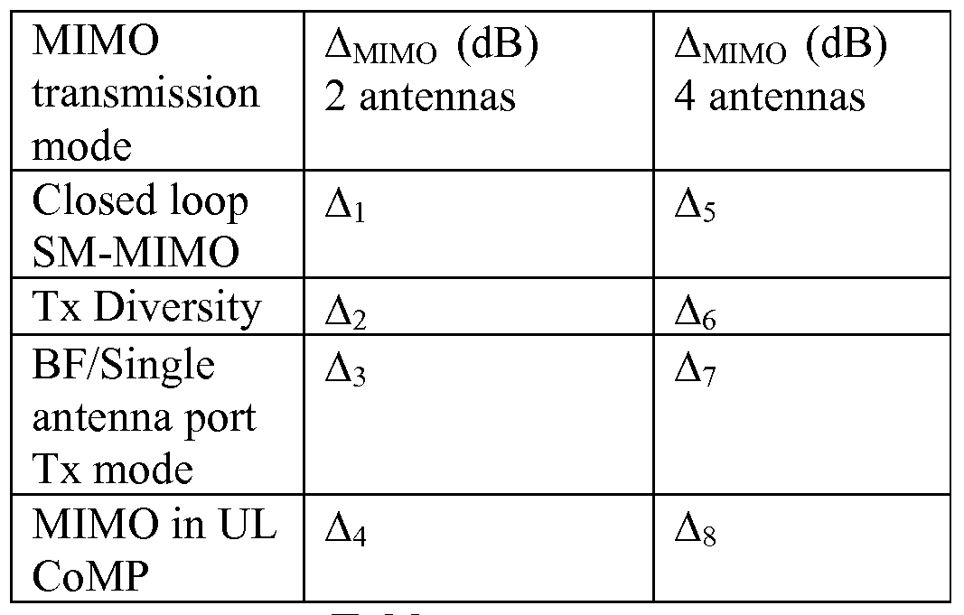
Table 1
[0037] For example, Δi and Δ2 could be 1 and -3 dB, respectively and Δ3 could be O dB. If a lookup table is used for ΔMIMOO)? it niay be the same for all WTRUs and may be broadcast. In this case, the WTRU selects from the lookup table a value of ΔMIMOO) corresponding to the MIMO transmission mode in use. [0038] Alternatively, the base station may signal a value(s) of ΔMIMOO) to a
WTRU, where the value(s) is a function of the MIMO transmission mode and j.
For example, for a given MIMO transmission mode and j, ΔMIMOO') niay be signaled via RRC signaling, Ll signaling or other higher layer signaling. [0039] Alternatively, the value of ΔMIMOO') mav be absorbed in PO.PUSCHO)
(e.g., PO_UE_PUSCHO))- In this case, the range of PO.PUSCHO) or PO_UE_PUSCHO) may need to be revised accordingly.
[0040] If accumulation transmit power control (TPC) command is enabled for a WTRU (based on the WTRU-specific parameter Accumulation-enabled provided by higher layers), then when a MIMO transmission mode is reconfigured for the WTRU from one mode to another mode, the WTRU may reset or adjust the state of the accumulation function, f(i), in Equation (1), e.g., the power control algorithm may be adjusted to account for how recent the available information in the accumulation function is, and reset or load f(i) with a value that is based on the previous state of f(i) when it was last used for this MIMO transmission mode and the time since it was last used, i.e., depending on the time since it was last used, the WTRU decides whether using a value or not is still valid.
[0041] Described herein are example power control methods using rank adaptation. In closed loop UL SM-MIMO, the transmission rank may be adapted dynamically. When rank for a WTRU is changed (from a higher rank to a lower rank or vice versa, e.g., from rank 2 to rank 1 or from rank 1 to rank 2), the effective antenna/MIMO gain for a transport block (codeword) may be changed accordingly. In this case, it is desirable for the WTRU to adjust the transmit power of the transport block (codeword) such that the received power (or SNR) of the transport block remains in the vicinity of a target power (or SNR). [0042] For instance, when rank for a WTRU is switched from Rank 2 to
Rank 1 (e.g., due to a channel condition change in spatial correlation), typically, without adjustment of the power control algorithm, the effective transmit power per information bit (or coded bit) for Rank 1 may be higher than that for Rank 2 (like x dB higher). In this case, in order to reduce the interference (for the case of higher rank to lower rank ) to other WTRU(s) in neighboring cells or meet the target requirement (for the case of lower rank to higher rank), the WTRU
transmit power may need to be adjusted accordingly. This adjustment may be done with the TPC command sent from the base station, however, this type of adjustment takes time to converge. Alternatively, the MIMO offset parameter, ΔMIMO, may be applied as in Equation (1) where the lookup table may be extended for the rank adaptation case and the benefit of immediate mode based power adaptation is realized. For illustration purposes this is shown in Table 2 for some chosen j and possibly different antenna configuration (2, 3, and 4 antennas). The entries in the table may be cell specific (e.g., provided by SIBs), WTRU specific (e.g., provided by RRC signaling) or fixed. For a given MIMO transmission mode, some of the entries in the table, corresponding to different numbers of antennas, may be the same (e.g., A62 = Δ63 = A64). Alternatively, the base station may signal a value(s) of ΔMIMOO") to a WTRU, where the value(s) is a function of the MIMO transmission mode and j. For example, for a given MIMO transmission mode (and rank in closed loop SM-MIMO) and j, ΔMIMOO) mav be signaled via RRC signaling, Ll signaling or other higher layer signaling.
MIMO ΔMIMO (dB) ΔMIMO (dB) ΔMIMO (dB) transmission 2 antennas 3 antennas 4 antennas mode
Closed loop Δ12 Δl3 Δ14
SM-MIMO:
Rankl
Closed loop Δ22 Δ23 Δ24
SM-MIMO:
Rank2
Closed loop Δ33 Δ34
SM-MIMO:
Rank3
Closed loop Δ44
SM-MIMO:
Rank4
Tx Diversity Δ52 Δ53 Δ54
BF/Single Δ62 Δ63 Δ64 antenna port mode
MIMO in UL Δ72 Δ73 Δ74
CoMP
Table 2
[0043] If accumulation TPC command is enabled for a WTRU (based on the
WTRU-specific parameter Accumulation- enabled provided by higher layers), then when rank is changed (e.g., rank 2 to rank 1), the WTRU may reset or adjust the state of the accumulation function, f(i), in Equation (1), e.g., the power control algorithm may be adjusted to account for how recent the available information in the accumulation function is, and reset or load f(i) with a value that is based on the previous state of f(i) when it was last used for this MIMO transmission mode (and rank) and the time since it was last used.
[0044] Described herein is power control for two codeword transmissions in
SM-MIMO. Described first is per codeword (CW) power control. When two codewords (CWs) are transmitted over multiple layers (e.g., up to at least 4 layers) in LTE-A UL SM-MIMO, the power control may be defined per codeword or per layer. In the case of per codeword power control, the setting of the WTRU transmit power for the k-th codeword PUSCH (k=l, 2) in subframe i may be defined as follows:
PPUSCHHΛ) = min{PCMAX,lO\ogw(MPUSCH(i)) + PO PUSCH(j,k)
+ a(j) ■ PL + ATF (/, k) + f(i, k) + AM1MO( /)} (2) k =1, 2, where i is the subframe index and k is the codeword index value associated with a transport block.
[0045] In Equation (2), PCMAX is the configured WTRU maximum transmit power and could alternatively be defined per codeword, PcMAx(k).
[0046] MpuscH is the bandwidth of the PUSCH resource assignment expressed in the number of resource blocks valid for a subframe. MpuscH is common to the two CWs.
[0047] Po_PuscH(j\k) is the codeword specific open loop parameter (in this case, for the k-th CW). This is for handling different targets (e.g., SINR) for different CWs. Particularly, since PCLPUSCH is composed of the sum of a cell specific nominal parameter, PO_NOMINAL_PUSCH, and a WTRU specific component,
PO_UE_PUSCH, and the cell specific parameter, PO_NOMINAL_PUSCH, would be common to both the CWs, different targets for different CWs are reflected in
Po_UE_puscH(j\k)- Alternatively, PCLPUSCH maybe common to both the CWs, rather than being CW specific, for example, when the target requirements are the same for the CWs. In that case, the index, k, within the parenthesis in the term
Po_PuscH(j\k) may be removed.
[0048] PL is the pathloss estimate calculated in the WTRU as in LTE.
Alternatively (or in the case of per layer power control), PL may be defined per layer (or transmit antenna).
[0049] The term ΔτF(i,k), modulation code factor, is to compensate for the different modulation code schemes (MCS) (than a reference MCS) used for the k- th CW, assuming each CW has its own MCS level which is provided by the eNB.
That is, ΔτF(i,k) is MCS dependent. ΔτF(i,k) may be defined as:
 for Ks = 1.25 and ΔτF(i,k) = 0 for Ks = 0, where Ks is given by the WTRU specific parameter deltaMC S- Enabled provided by higher layers, as specified in LTE.
MPR(k) = OCQ1(k)INRE(k) is used for control data sent via PUSCH without uplink shared channel (UL- SCH) data (where MPR is modulation x code rating) and
 is for other PUSCH transmission cases. C(k) is the number of code blocks for the k-th CW, Kr(k) is the size for code block r in the k-th CW, OcQi(k) is the number of CQI bits including cyclic redundancy check (CRC) bits where the CQI bits may be transmitted over the layer(s) associated with the k-th CW. NRE(k) is the number of resource elements determined as:
1SI RE \K) ~ 1SI AK) M SC 7V symb
•> where Ni(k) is the number of layers associated with the k-th CW transmission.
T1 I PUSCH '-initial τy-PUSCH-imtial sc and symb are common to the two CWs and defined in LTE.
[0050] The parameter f(i,k) is the (closed loop) power control adjustment state for the k-th CW if the TPC command is defined per CW. In this case, the TPC commands for the CWs may be signaled separately in physical downlink control channel (PDCCH) or jointly coded/signaled in PDCCH. In either case, a new downlink control indicator (DCI) format may be needed. Alternatively, it may be possible to have a single closed loop TPC command to control the two CWs. In this case, f(i,k) becomes f(i).
[0051] ΔMIMOO) is as defined previously. Alternatively, ΔMIMOQ niay be set to zero for SM-MIMO. In that case, ΔMIMOQ m&y be removed from Equation (2). [0052] In UL SM-MIMO transmission, the signals transmitted from multiple layers/antennas may interfere with each other at the base station receiver, that is, cross layer interference may exist. Such cross layer interference causes the effective interference/noise level at the receiver to be increased
(equivalently reducing SINR). In this case, the WTRU may need to compensate for the increased interference due to cross layer interference by adjusting its transmit power accordingly. There are several possible methods to compensate for the cross layer interference.
[0053] In one example method, a compensation term may be introduced into Equation (2) to compensate for cross layer compensation factor and is reflected in Equation (3):
PpuscH (U k) = min {PCMAX , 10 log10 (MPUSCH (/)) + P0 PUSCH (j, k)
(3) + a(j) ■ PL + ATF (/, k) + f(i, k) + AMIMO(j) + AInt }
Is. = 1,2 where Δint is a cross layer interference compensation term. The term Δint may be calculated by the WTRU using several UL MIMO relevant parameters that are configured by the base station, for example, the number of ranks/layers, combinations of MCSs for the individual codewords, and/or (relative) power levels of the respective codewords. Alternatively, a look-up table for Δint may be provided by the base station through RRC signaling.
[0054] Alternatively, the cross layer interference compensation term may be embedded into ΔMIMO in Equation (3). Alternatively, the cross layer interference terms may be defined per codeword like Δint(k) for k=l,2 where Δint(k) is a function of MIMO transmission mode, including the number of layers/ranks, and the power of the other codeword (i.e. interfering codeword). [0055] When a CW is mapped to more than one layer, then the transmit power for the CW is distributed evenly among the associated layers. Alternatively, the transmit power for the CW may be split relatively among the layers taking into account antenna gain imbalance (AGI) between the antennas, pathloss difference(s) between the antennas, statistics of received TPC commands, and/or other similar factor(s)/metric(s).
[0056] If accumulation TPC command is enabled for a WTRU (based on the
WTRU-specific parameter Accumulation- enabled provided by higher layers), then when the number of codewords in SM-MIMO is changed (e.g., from two
codewords to one codewords or vice versa), the WTRU may reset or adjust the state of the accumulation function, f(i) or f(i,k), in Equation (2) and (3), e.g., the power control algorithm may be adjusted to account for how recent the available information in the accumulation function is, and reset or load f(i) (or f(i,k)) with a value that is based on the previous state of f(i) (or f(i,k)) when it was last used for this MIMO transmission mode (and rank) and the time since it was last used. [0057] Described herein are example maximum power scaling methods for per codeword power control. After calculating the power of each CW (according to Equation (2) or Equation (3)), if the sum of the powers of the two CWs exceeds the WTRU maximum power, PCMAX, (i.e., , PpuscH(i,l)+ PpuscH(i,2) > PCMAX), then the WTRU adjusts the power of each CW using one of several maximum power scaling methods.
[0058] In a first example, assuming that PCMAX is defined as the total
WTRU maximum power (regardless of the number of power amplifiers (PAs) in the WTRU), then the transmit powers of PpuscH(i,l) and PpuscH(i,2) may be evenly reduced such that the sum of the reduced powers is equal to PCMAX. Alternatively, the transmit powers of PpuscH(i,l) and PpuscH(i,2) may be reduced by a relative scaling such that PpuscH(i,l) = PpuscH(i,l) - Δ*( PpuscH(i,l)/( PpuscH(i,l) + PpuscH(i,2))) and PPUscH(i,2) = PPUscH(i,2) - Δ*( PpuscH(i,2)/(
PpuscH(i,l) + PpuscH(i,2))), where Δ is the reduction amount required for the maximum power constraint such that PpuscH(i,l)+ PpuscH(i,2) = PCMAX after the power scaling.
[0059] In a second example, the CW may be dropped if its required power level exceeds PCMAX by a predefined threshold. Alternatively, the sum of the powers of the two CWs exceeds the WTRU maximum power, PCMAX, (i.e., , PpuscH(i,l)+ PpuscH(i,2) > PCMAX), then one of the CWs is dropped. The dropping may be based on CW priority such as dropping a CW with lower priority. [0060] In a third example, if PCMAX is defined per PA and one CW is transmitted through a single PA (e.g., no layer shift), then no further transmit power adjustment is required.
[0061] Described herein are example methods for per PUSCH power
control, the WTRU may firstly determine the total WTRU transmit power of PUSCH in SM-MIMO as follows:
PpuscπiJ) = ™n{PCMAχ,
 + PO_PUSCHU)
+ a(j) ■ PL + q(ATF(i,l),ATF(i,2)) + f(i) + AMIMO( j)} <4>
[0062] In Equation 4, all the parameters in the above equation as defined in Equation (1), except for q(ΔτF(i,l), ΔτF(i,2)) where q(ΔτF(i,l), ΔτF(i,2)) represents a function of ΔτF(i,l) and ΔτF(i,2). The terms ΔτF(i,l) and ΔτF(i,2) as defined in Equation (2). For example, q(ΔτF(i,l), ΔτF(i,2)) = a*ΔτF(i,l) + b*ΔτF(i,2) where a>=0, b>=0 satisfying a+b=2, for example, a=l and b=l (or satisfying a+b=l, for example, a=0.5 and b=0.5). That is, both ΔτF(i,l) and ΔτF(i,2) (i.e., the two MCSs) for codeword 1 and codeword 2, respectively, are taken into account for the calculation of the total power of PUSCH carrying codeword 1 and codeword 2 in SM-MIMO. All the other power control parameters in Equation (4) are common to the two codewords. ΔMIMOQ niay include the cross layer interference factor, as mentioned previously.
[0063] Alternatively, the total transmit power of PUSCH in SM-MIMO may be defined as follows:
PpuscπiJ) = ™n{PCMAχ,
 + PO_PUSCHU)
+ a(j) ■ PL + ATF (0 + /(O + ΔM/MO( J) } (5)
[0064] In Equation 5, ΔTF© would be dependent of both MCSs (or combined
MCS) of codeword 1 and codeword 2, respectively. For example, ΔTF© could be calculated to take into account the combined impact of the both MCSs. For example, ΔTF© may be defined as:
 for Ks = 1.25 and ΔTF© = 0 for Ks = 0, where,
 is used for control data sent via PUSCH without uplink shared channel (UL- SCH) data and
 is for other PUSCH transmission cases where α>=0, β>=0 satisfying α + β =1, for example, α =0.5 and β =0.5 (or satisfying α + β = 2, for example, α =1 and β =1). The terms C(I) and C(2), respectively, are the number of code blocks for codeword 1 and codeword 2, respective. The terms K1-(I) and Kr(2), respectively, are the size for code block r in codeword 1 and codeword 2, respectively. The terms OCQI(I) and OCQI(2), respectively, are the number of CQI bits including cyclic redundancy check (CRC) bits where the CQI bits may be transmitted over the layer(s) associated with codeword 1 and codeword 2, respectively. NRE(k) for k=l,2 is the number of resource elements for the k-th codeword, determined as: ^2
 where Νi(k) is the number of layers associated with the k-th codeword transmission.
The terms:
M SC ^ symb are common to the two codewords and defined in LTE. The equation for ΔτF(i) could also include a term that builds a compensation for cross-layer interference. Alternatively, the cross layer interference may be compensated for through another term configured and signaled by the network (e.g., ΔMIMO, f(i), or other similar terms).
[0065] Once the total power is determined according to either Equation (4) or Equation (5), the total transmit power is then distributed equally between the two codewords. Alternatively, different power distribution factors may be used for codeword 1 and codeword 2, respectively. For example, PPUSCH© = c*PpuscH(i,l) + d*PpuscH(i,2) where 0<=c<=l, 0<=d<=l satisfying c+d = 1. The power distribution factors, c and d, may be configured semi-statically through higher layer signaling. Alternatively, the WTRU may autonomously determine the power distribution factors, for example, based on PL difference between the CWs (or antennas associated with the CWs), MCS difference between the CWs, AGI,
statistics of received TPC commands, or other similar factors or metrics. Alternatively, a semi-static power offset between the two codewords may be used such that PpuscH(i,2) = PpuscH(i) - 3 - powerOffset (dBm) and PpuscH(i,l) = PpuscH(i) - 3 + powerOffset (dBm) where powerOffset (dB) may be configured through higher layer signaling. Alternatively, the WTRU may autonomously determine the power offset, for example, based on PL difference between the CWs (or antennas associated with the CWs), MCS difference between the CWs, AGI, statistics of received TPC commands, or other similar factors or metrics. [0066] If a codeword is transmitted over multiple layers or antennas, then the codeword power is equally distributed between the layers or antennas. Alternatively, the transmit power for the CW may be split relatively among the layers, taking into account the AGI among the antennas, pathloss difference(s) among the antennas, statistics of received TPC commands, and/or other similar factor (s)/metric (s) .
[0067] Figure 4 shows an example double codeword transmitter block diagram 400 that may use the methods described herein. Transmitter block diagram 400 illustrates a codeword generation block 405 that feeds into a power setting module or circuit 410. Power setting module or circuit 410 uses the methods described herein. The output of the power setting module or circuit 410 is an input into the transmission block 415, where the two codewords are transmitted at the respective determined power levels through the two antennas, respectively.
[0068] Described herein are example methods for power control in UL
MIMO CoMP. In UL CoMP, there may be multiple PL measurements available from different base stations or relays. Different scenarios are presented on how the WTRU uses PL measurements.
[0069] In scenario 1, the WTRU does not know it is in CoMP in the UL.
The WTRU may not be aware that it is in UL CoMP. From a WTRU perspective, there may be no modifications required for the WTRU procedure. However, in UL CoMP where multiple cells receive the UL signal, the anchor or primary cell
(which sends the PDCCH to the WTRU) sends the WTRU TPC command which
may be based on received signal measurements (e.g., after combing all the UL signals) from all the cooperative cells.
[0070] Alternatively, all the cooperative cells may generate their own TPC command and send them to the anchor cell. The anchor cell combines the received TPC commands (from non-anchor cells) and then generates a single TPC command, which will be sent to the WTRU. This method may be applicable to cases described below.
[0071] When the WTRU enters UL CoMP mode and if accumulation is enabled, the base station may send the WTRU an indicator to reset the accumulation function f(i), where the indicator may be signaled via Ll/2 or higher layers. Upon receiving the indicator, the WTRU may reset f(i).
[0072] Alternatively, when the WTRU enters UL CoMP mode, the anchor cell may update PO_UE_PUSCH and send it (even the value of PO_UE_PUSCH is not changed) to the WTRU. Upon receiving PO_UE_PUSCH, the WTRU may reset accumulation f(i), if accumulation is enabled or if the TPC command is included in a PDCCH with DCI format 0.
[0073] In scenario 2, the WTRU knows it is in CoMP in UL, but not told which other base stations or relays may be listening. Path loss measurements from other nearby base stations or relays may be made by the base stations. No
TPC bits are sent from other base stations or relays that may be listening. Base stations determine the effective PL (e.g., in terms of the same block error probability) assuming that the both own cell and best non-own cell(s) device is listening to the transmission. The method to combine the PL measurements may in principle depend on the type of combining done at the base stations or relays
(e.g., no combining, soft combining,...). For example, the PL definition may be modified where the PL is the downlink pathloss estimate calculated in the base stations in dB, and in the case of UL CoMP, the PL of multiple cells may be combined.
[0074] The PL(i) = referenceSignalPower(i) - higher layer filtered RSRP(i), where referenceSignalPower(i) is provided by higher layers for each cell i, and
RSRP is defined for each cell(i)and the higher layer filter configuration is defined
LTE.
[0075] The combining may be done in several ways. In one method, the minimum value is used, e.g., PL = min{PL(i)} i=l...N. In another method, the PL may be defined as equal gain combining, PL = 1/N * (Sum of PL(i)). [0076] When the WTRU knows that it enters UL CoMP mode and if accumulation is enabled, the WTRU may reset f(i).
[0077] In scenario 3, the WTRU knows it is in CoMP in UL and knows at least one other listener. The path loss measurements from other nearby base stations or relays are made by the WTRU for the cells participating in UL CoMP. TPC bits are sent from other base stations or relays that may be listening. The TPC bits may be physically sent to WTRU from a single point and included in a single PDCCH. The WTRU may maintain a power control loop for each CoMP UL target and combine the computed required power for the UL transmission. A combining method may be to select the smallest power, with a possible additional offset. For example, the required UL power is computed for each cell in UL CoMP (k) as:
PpuscH(i)k = min{P^401og10(Mprørø(0) + P0 _PUSalJ)
+ a(j)-PLk +ATF(i) + f(i)k} and the final computed required power (before any backoff) is then:
^PUSCH (0 = minføjscH (0 k )- ^CoMP k = \ .X where K is the number of participating cell in UL CoMP and ΔcoMP is a parameter (or a table in the event that ΔcoMP is a function of K) provided by higher layers. [0078] When the WTRU knows that it enters UL CoMP mode and if accumulation is enabled, the WTRU shall reset f(i).
[0079] Alternatively, when the WTRU enters UL CoMP mode (including all the above three cases), the anchor cell shall update PO_UE_PUSCH and send it (even the value of PO_UE_PUSCH is not changed) to the WTRU. Upon receiving PO_UE_PUSCH, the WTRU may reset accumulation f(i), if accumulation is enabled or if the TPC command is included in a PDCCH with DCI format 0.
[0080] For a WTRU in uplink CoMP, the base station from where it receive
its uplink scheduling grant is called the anchor base station for this WTRU. [0081] The following methods may be used for path loss metric in UL power control for WTRU in uplink CoMP for the path loss used in the uplink power control formula. In one example, the weighted average of path loss from different base stations may be used. The path loss from the anchor base station has the largest weight, and non-anchor base stations have the same weight, which is smaller than the weight of the anchor base station. Alternatively, equal weights may be used.
[0082] In another example, only the path loss from the anchor base station may be used and does not include path loss from non-anchor base statiosn in the TPC formula. In yet another example, the best (e.g., smallest) path loss may be used and does not include other path losses in the TPC formula. In still another example, the worst (e.g., largest) path loss may be used and does not include other path losses in the TPC formula.
[0083] The transmit power control command for the WTRU in uplink CoMP may be generated by each base station in the uplink CoMP active set. TPC commands sent by those non-anchor base stations may only be in accumulation mode. TPC commands sent by the anchor base station may be in either absolute or accumulation mode. There are several ways for the WTRU to combine TPC commands received from different base stations. In one method, a voting method may be used. In one option of the voting method, a majority vote may be used. In another option, the anchor base station has an overrule priority. [0084] In another method, a weighted average may be used. The TPC command from the anchor base station has the largest weight, and non-anchor base stations have the same weight, which is smaller than the weight of the anchor base station. Alternatively, the TPC command from each base station may be weighted according to its path loss (normalized to the best path loss). That is, the TPC command from the strongest cell (with the smallest path loss) has the largest weight and so on. In another alternative, equal weights may be used across all base stations.
[0085] Described herein are signaling/configuration/procedure aspects for
CoMP that may affect UL power control. Both downlink (DL) CoMP and UL CoMP may be supported in LTE-A and example methods are provided when the WTRU is in both DL CoMP and UL CoMP simultaneously. In a first case, only one CoMP configuration is used in RRC signaling for both UL/DL. That is, if the WTRU receives RRC signaling to inform the WTRU is in CoMP, the WTRU is automatically in both DL CoMP and UL CoMP simultaneously. Procedure for UL power control for UL CoMP assuming DL is also in CoMP should be used. [0086] In a second case, separate CoMP configurations may be used for UL and DL. In this case, separate RRC signalings and configurations may be used, one for DL CoMP and one for UL CoMP. WTRU receives RRC signaling to inform the WTRU if it is in CoMP or not in either UL, DL or both UL/DL. If the WTRU is in UL CoMP but not in DL CoMP, procedure for UL power control for UL CoMP assuming DL is not in CoMP should be used. If the WTRU is not in UL CoMP but in DL CoMP, procedure for UL power control for non-UL CoMP assuming DL is in CoMP should be used. If the UE is in CoMP for both UL/DL, it is similar to case 1 and procedure for UL power control for UL CoMP assuming DL is also in CoMP should be used. Otherwise procedure for UL power control for non-CoMP for both UL/DL should be used. [0087] Embodiments
[0088] 1. A method for uplink power control in multiple-input multiple- output (MIMO), comprising determining a MIMO transmission mode. [0089] 2. The method of embodiment 1, further comprising adjusting a transmit power level with a MIMO power offset in accordance with the MIMO transmission mode.
[0090] 3. The method of any of the preceding embodiments, wherein the MIMO power offset is for a physical uplink shared channel (PUSCH) transmission in a subframe.
[0091] 4. The method of any of the preceding embodiments, wherein uplink power control is performed per codeword (CW) per subframe. [0092] 5. The method of any of the preceding embodiments, wherein the MIMO power offset is wireless transmit/receive unit (WTRU) specific.
[0093] 6. The method of any of the preceding embodiments,, wherein the MIMO power offset is provided by at least one of a look-up table, higher layer signaling, WTRU- specific signaling, broadcast signaling or predefined.
[0094] 7. The method of any of the preceding embodiments, wherein the MIMO power offset is part of an open loop parameter.
[0095] 8. The method of any of the preceding embodiments, further comprising resetting an accumulation function upon WTRU reconfiguration from a first MIMO transmission mode to a second MIMO transmission mode.
[0096] 9. The method of any of the preceding embodiments, wherein the MIMO power offset is used to adjust for rank adaptation.
[0097] 10. The method of any of the preceding embodiments, further comprising resetting an accumulation function upon rank adaptation.
[0098] 11. The method of any of the preceding embodiments, further comprising adjusting the transmit power level with a cross layer interference compensation factor.
[0099] 12. The method of any of the preceding embodiments, further comprising determining the cross layer interference compensation factor based on parameters provided by a base station.
[0100] 13. The method of any of the preceding embodiments, wherein the cross layer interference compensation factor is part of the MIMO power offset.
[0101] 14. The method of any of the preceding embodiments, wherein the MIMO power offset includes a cross layer interference compensation factor.
[0102] 15. The method of any of the preceding embodiments, wherein a transmit power level for a codeword is distributed evenly among layers to which the codeword in mapped.
[0103] 16. The method of any of the preceding embodiments, further comprising resetting an accumulation function upon a change in a number of codewords.
[0104] 17. The method of any of the preceding embodiments, further comprising reducing a transmit power of codewords evenly upon exceeding a
WTRU maximum power.
[0105] 18. The method of any of the preceding embodiments, further comprising reducing a transmit power of codewords on a relative scale basis upon exceeding a WTRU maximum power.
[0106] 19. The method of any of the preceding embodiments, further comprising dropping a codeword upon a transmit power of the codeword exceeding a threshold.
[0107] 20. The method of any of the preceding embodiments, further comprising dropping a codeword based on a priority basis.
[0108] 21. The method of any of the preceding embodiments, wherein the uplink power control is performed per PUSCH.
[0109] 22. The method of any of the preceding embodiments, wherein a modulation code scheme (MCS) factor is per codeword.
[0110] 23. The method of any of the preceding embodiments, wherein a modulation code scheme (MCS) factor includes a cross layer interference compensation factor.
[0111] 24. The method of any of the preceding embodiments, wherein a transmit power level is distributed in a predetermined manner among all codewords.
[0112] 25. The method of any of the preceding embodiments, wherein the MIMO offset factor is determined by the wireless transmit/receive unit
(WTRU).
[0113] 26. The method of any of the preceding embodiments, wherein the MIMO offset factor is determined from at least one of a path loss difference between codewords, an antenna gain imbalance, or received transmit power control statistics.
[0114] 27. A wireless transmit/receive unit (WTRU) for performing uplink power control in MIMO, comprising a receiver configured to receive a
MIMO transmission mode.
[0115] 28. The WTRU of embodiment 27, further comprising a codeword generator configured to input data and generate at least one codeword.
[0116] 29. The WTRU of embodiments 27-28, further comprising a power setting circuit configured to determine a transmit power level including adjusting the transmit power level with a MIMO power offset in accordance with the
MIMO transmission mode.
[0117] 30. The WTRU of embodiments 27-29, further comprising a transmitter configured to transmit the at least one codeword at the adjusted transmit power level.
[0118] 31. The WTRU of embodiments 27-30, further comprising the power setting circuit further configured to adjust the transmit power level with a cross layer interference compensation factor.
[0119] 32. The WTRU of embodiments 27-31, wherein the transmit power control is performed per codeword (CW) per subframe.
[0120] 33. The WTRU of embodiments 27-32, wherein the transmit power control is performed per PUSCH.
[0121] 34. A method of power control in multiple in- multiple out
(MIMO), comprising setting a transmit power level for a physical uplink shared channel (PUSCH) transmission in a subframe.
[0122] 35. The method of embodiment 34, wherein there is one codeword
(CW) per subframe.
[0123] 36. The method of embodiments 34-35, where ΔMIMO© is a MIMO offset provided by higher layers.
[0124] 37. The method of embodiments 34-36, where a value of ΔMIMOQ is absorbed.
[0125] 38. The method of embodiments 34-37, wherein for multiple layers, PC is defined per layer.
[0126] 39. The method of embodiments 34-38, where different values of
ΔTF are applied for each of a layer.
[0127] 40. The method of embodiments 34-39, wherein a transport power command (TPC) is defined per layer.
[0128] 41. The method of embodiments 34-40, wherein rank adaptation is performed.
[0129] 42. The method of embodiments 34-41, wherein a PC procedure is performed when a rank is switched from a lower rank to a higher rank or a higher rank to a lower rank.
[0130] 43. The method of embodiments 34-42, wherein transmit power is adjusted using a MIMO offset parameter.
[0131] 44. The method of embodiments 34-43, wherein multiple an anchor cell send a TPC command based on received signal measurements from all cooperative cells.
[0132] 45. The method of embodiments 34-44, where all cooperative cells generate their own TPC commands and send them to the anchor cell.
[0133] 46. The method of embodiments 34-45, wherein the anchor cell combines received TPC commands and generates a single TPC command.
[0134] 47 The method of embodiments 34-46, wherein an indicator is sent to reset an accumulator function f(i).
[0135] 48. The method of embodiments 34-47, wherein an anchor cell updates PO_UE_PUSCH and sends it to a wireless transmit/receive unit (WTRU).
[0136] 49. The method of embodiments 34-48, further comprising resetting f(i) if accumulation is enabled or if a TPC command is included in a
PDCCH with CDI format 0.
[0137] 50. The method of embodiments 34-49, wherein a pathloss is determined as a downlink pathloss estimate calculated in dB.
[0138] 51. The method of embodiments 34-50, wherein pathloss is calculated in accordance with the following: PL(i) = referenceSignalPower(i) — higher layer filtered RSRP(i), where referenceSignalPower(i) is provided by higher layers for each cell i, and RSRP is predefined for each cell(i) and the higher layer filter configuration is predefined.
[0139] 52. The method of embodiments 34-51, wherein a combining is performed of pathloss.
[0140] 53. The method of embodiments 34-52, wherein a combining of pathloss is performed by using a minimum pathloss combining.
[0141] 54. The method of embodiments 34-53, wherein a combining of
pathloss i sby equal gain combining.
[0142] 55. The method of embodiments 34-54, wherein a pathloss metric is determined from a weighted of pathloss from different Node Bs.
[0143] 56. The method of embodiments 34-55, wherein a path loss from an anchor NodeB has the largest weight, and non-anchor NodeBs have the same weight which is smaller than the weight of anchor NodeB.
[0144] 57. The method of embodiments 34-56, wherein all Node Bs have equal weight.
[0145] 58. The method of embodiments 34-57, wherein the path loss from an anchor NodeB is used and does not include path loss from non-anchor
NodeBs in the TPC formula.
[0146] 59. The method of embodiments 34-58, wherein the smallest path loss is used and does not include other path losses in the TPC formula.
[0147] 60. The method of embodiments 34-59, wherein the largest path loss is used and does not include other path losses in the TPC formula.
[0148] 61. The method of embodiments 34-60, wherein a transmit power control command for in uplink COMP is generated by each NodeB in the uplink
COMP active set.
[0149] 62. The method of embodiments 34-61, wherein a TPC command sent by non-anchor NodeBs is used in accumulation mode.
[0150] 63. The method of embodiments 34-62, wherein a TPC command sent by an anchor NodeB can be in either absolute or accumulation mode.
[0151] 64. The method of embodiments 34-63, wherein TPC commands are combined by a voting method.
[0152] 65. The method of embodiments 34-64, wherein a majority voting method is used for combining TPC commands.
[0153] 66. The method of embodiments 34-65, wherein an anchor Node B has an overrule priority.
[0154] 67. The method of embodiments 34-66, wherein TPC commands are combined by a weighted average.
[0155] 68. The method of embodiments 34-67, wherein any of the
following weighted averages are utilized: a TPC command from an anchor NodeB has the largest weight, and non-anchor NodeBs have the same weight which is smaller than the weight of anchor NodeB, a TPC command from each NodeB is weighted according to its path loss (normalized to the best path loss) where the
TPC command from the strongest cell (with the smallest path loss) has the largest weight, and/or equal weight is used across all NodeBs.
[0156] 69. The method of embodiments 34-68, wherein one CoMP configuration is used in RRC signaling for both UL/DL.
[0157] 70. The method of embodiments 34-69, wherein separate CoMP configurations are used for UL and DL.
[0158] 71. The method of embodiments 34-70, wherein a procedure for
UL power control for UL CoMP assuming DL is not in CoMP is used.
[0159] 72. The method of embodiments 34-71, wherein a procedure for
UL power control for non-UL CoMP assuming DL is in CoMP is used.
[0160] 73. The method of embodiments 34-72, wherein a procedure for
UL power control for UL CoMP assuming DL is also in CoMP is used.
[0161] 74. The method of embodiments 34-73, wherein a procedure for
UL power control for non-CoMP for both UL/DL is used.
[0162] 75. The method of embodiments 34-74, wherein an open loop component of uplink TPC is common to two CWs.
[0163] 76. The method of embodiments 34-75, wherein f(i,k) is the power control adjustment state for a k-th CW.
[0164] 77. The method of embodiments 34-76, wherein a transmit power for a codeword is adjusted where on a condition that the sum of the required power levels is greater than Pmax, PpuscH(i,l) and PpuscH(i,2) are reduced evenly such that the sum of the reduced powers is equal to Pmax, or PpuscH(i,l) and
PpuscH(i,2) are reduced by a relative scaling.
[0165] 78. The method of embodiments 34-77, wherein a relative scaling is PpuscH(i,l) = PpuscH(i,l) - Δ*( PpuscH(i,l)/( PpuscH(i,l) + PpuscH(i,2))) or
PpuscH(i,2) = PpuscH(i,2) - Δ*( PpuscH(i,2)/( PpuscH(i,l) + PpuscH(i,2))), where Δ is the reduction amount required for the maximum power constraint.
[0166] 79. The method of embodiments 34-78, further comprising dropping a CW on a condition that its required power level exceeds Pmax by a predefined threshold.
[0167] 80. The method of embodiments 34-79, wherein on a condition that Pmax is defined per PA and one CW is transmitted through a single PA, no further transmit power adjustment is required.
[0168] Although features and elements are described above in particular combinations, each feature or element can be used alone without the other features and elements or in various combinations with or without other features and elements. The methods or flow charts provided herein may be implemented in a computer program, software, or firmware incorporated in a computer- readable storage medium for execution by a general purpose computer or a processor. Examples of computer-readable storage mediums include a read only memory (ROM), a random access memory (RAM), a register, cache memory, semiconductor memory devices, magnetic media such as internal hard disks and removable disks, magneto-optical media, and optical media such as CD-ROM disks, and digital versatile disks (DVDs).
[0169] Suitable processors include, by way of example, a general purpose processor, a special purpose processor, a conventional processor, a digital signal processor (DSP), a plurality of microprocessors, one or more microprocessors in association with a DSP core, a controller, a microcontroller, Application Specific Integrated Circuits (ASICs), Application Specific Standard Products (ASSPs); Field Programmable Gate Arrays (FPGAs) circuits, any other type of integrated circuit (IC), and/or a state machine.
[0170] A processor in association with software may be used to implement a radio frequency transceiver for use in a wireless transmit receive unit (WTRU), user equipment (UE), terminal, base station, Mobility Management Entity (MME) or Evolved Packet Core (EPC), or any host computer. The WTRU may be used in conjunction with modules, implemented in hardware and/or software including a Software Defined Radio (SDR), and other components such as a camera, a video camera module, a videophone, a speakerphone, a vibration
device, a speaker, a microphone, a television transceiver, a hands free headset, a keyboard, a Bluetooth® module, a frequency modulated (FM) radio unit, a Near Field Communication (NFC) Module, a liquid crystal display (LCD) display unit, an organic light- emitting diode (OLED) display unit, a digital music player, a media player, a video game player module, an Internet browser, and/or any Wireless Local Area Network (WLAN) or Ultra Wide Band (UWB) module.
Claims
1. A method for uplink power control in multiple-input multiple-output (MIMO), comprising: determining a MIMO transmission mode; and adjusting a transmit power level with a MIMO power offset in accordance with the MIMO transmission mode.
2. The method of claim 1, wherein the MIMO power offset is for a physical uplink shared channel (PUSCH) transmission in a subframe.
3. The method of claim 1, wherein uplink power control is performed per codeword (CW) per subframe.
4. The method of claim 1, wherein the MIMO power offset is wireless transmit/receive unit (WTRU) specific.
5. The method of claim 1, wherein the MIMO power offset is provided by at least one of a look-up table, higher layer signaling, WTRU- specific signaling, broadcast signaling or predefined.
6. The method of claim 1, wherein the MIMO power offset is part of an open loop parameter.
7. The method of claim 1, further comprising resetting an accumulation function upon WTRU reconfiguration from a first MIMO transmission mode to a second MIMO transmission mode.
8. The method of claim 1, wherein the MIMO power offset is used to adjust for rank adaptation.
9. The method of claim 8, further comprising resetting an accumulation function upon rank adaptation.
10. The method of claim 1, further comprising adjusting the transmit power level with a cross layer interference compensation factor.
11. The method of claim 10, further comprising determining the cross layer interference compensation factor based on parameters provided by a base station.
12. The method of claim 10, wherein the cross layer interference compensation factor is part of the MIMO power offset.
13. The method of claim 1, wherein the MIMO power offset includes a cross layer interference compensation factor.
14. The method of claim 1, wherein a transmit power level for a codeword is distributed evenly among layers to which the codeword in mapped.
15. The method of claim 1, further comprising resetting an accumulation function upon a change in a number of codewords.
16. The method of claim 1, further comprising reducing a transmit power of codewords evenly upon exceeding a WTRU maximum power.
17. The method of claim 1, further comprising reducing a transmit power of codewords on a relative scale basis upon exceeding a WTRU maximum power.
18. The method of claim 1, further comprising dropping a codeword upon a transmit power of the codeword exceeding a threshold.
19. The method of claim 18, further comprising dropping a codeword based on a priority basis.
20. The method of claim 1, wherein the uplink power control is performed per PUSCH.
21. The method of claim 20, wherein a modulation code scheme (MCS) factor is per codeword.
22. The method of claim 1, wherein a modulation code scheme (MCS) factor includes a cross layer interference compensation factor.
23. The method of claim 1, wherein a transmit power level is distributed in a predetermined manner among all codewords.
24. The method of claim 1, wherein the MIMO offset factor is determined by the wireless transmit/receive unit (WTRU).
25. The method of claim 1, wherein the MIMO offset factor is determined from at least one of a path loss difference between codewords, an antenna gain imbalance, or received transmit power control statistics.
26. A wireless transmit/receive unitm(WTRU) for performing uplink power control in MIMO, comprising: a receiver configured to receive a MIMO transmission mode; a codeword generator configured to input data and generate at least one codeword; a power setting circuit configured to determine a transmit power level including adjusting the transmit power level with a MIMO power offset in accordance with the MIMO transmission mode; and a transmitter configured to transmit the at least one codeword at the adjusted transmit power level.
27. The WTRU of claim 26, the power setting circuit further configured to adjust the transmit power level with a cross layer interference compensation factor.
28. The WTRU of claim 26, wherein the transmit power control is performed per codeword (CW) per subframe.
29. The WTRU of claim 26, wherein the transmit power control is performed per PUSCH.
Applications Claiming Priority (2)
| Application Number | Priority Date | Filing Date | Title |
|---|---|---|---|
| US16095809P | 2009-03-17 | 2009-03-17 | |
| US61/160,958 | 2009-03-17 |
Publications (2)
| Publication Number | Publication Date |
|---|---|
| WO2010107885A2 true WO2010107885A2 (en) | 2010-09-23 |
| WO2010107885A3 WO2010107885A3 (en) | 2011-02-24 |
Family
ID=42740212
Family Applications (1)
| Application Number | Title | Priority Date | Filing Date |
|---|---|---|---|
| PCT/US2010/027624 WO2010107885A2 (en) | 2009-03-17 | 2010-03-17 | Method and apparatus for uplink power control in multiple-input multiple-output |
Country Status (4)
| Country | Link |
|---|---|
| US (3) | US8964868B2 (en) |
| AR (1) | AR075864A1 (en) |
| TW (4) | TWI496490B (en) |
| WO (1) | WO2010107885A2 (en) |
Cited By (21)
| Publication number | Priority date | Publication date | Assignee | Title |
|---|---|---|---|---|
| WO2011040858A1 (en) * | 2009-10-02 | 2011-04-07 | Telefonaktiebolaget Lm Ericsson (Publ) | Uplink power control in a wireless communication system |
| WO2012061685A1 (en) * | 2010-11-05 | 2012-05-10 | Qualcomm Incorporated | Dynamic uplink power control |
| CN102695261A (en) * | 2011-03-22 | 2012-09-26 | 中国移动通信集团公司 | Control method, apparatus and system of uplink power |
| CN102740434A (en) * | 2011-04-15 | 2012-10-17 | 上海贝尔股份有限公司 | Method and device for uplink power control |
| CN102946632A (en) * | 2011-08-15 | 2013-02-27 | 中兴通讯股份有限公司 | Uplink power control method of multiple-antenna system, and user terminal |
| WO2013049769A1 (en) * | 2011-09-30 | 2013-04-04 | Interdigital Patent Holdings, Inc. | Multipoint transmission in wireless communication |
| CN103179652A (en) * | 2011-12-23 | 2013-06-26 | 中兴通讯股份有限公司 | Method and device for matching uplink coverage with downlink coverage in network optimization |
| WO2013102485A1 (en) * | 2012-01-02 | 2013-07-11 | Huawei Technologies Co., Ltd. | Power control in a wireless communication system for uplink transmissions with coordinated reception |
| WO2013116108A1 (en) * | 2012-02-01 | 2013-08-08 | Motorola Mobility Llc | Uplink power control in coordinated multi-point wireless communication system |
| EP2709409A2 (en) * | 2011-05-10 | 2014-03-19 | LG Electronics Inc. | Method for determining uplink transmission power and user equipment |
| KR20140054261A (en) * | 2011-08-15 | 2014-05-08 | 삼성전자주식회사 | Methods and systems for dynamic switching, uplink power control and synchronization in wireless networks |
| WO2014162201A1 (en) * | 2013-04-03 | 2014-10-09 | Alcatel Lucent | Method and apparatus for uplink transmission power control of multi-link connections |
| US9603099B2 (en) | 2009-02-09 | 2017-03-21 | Interdigital Patent Holdings, Inc. | Apparatus and method for uplink power control for a wireless transmitter/receiver unit utilizing multiple carriers |
| EP3190839A4 (en) * | 2014-09-28 | 2017-08-23 | Huawei Technologies Co., Ltd. | Uplink power control method and device |
| WO2017165668A1 (en) * | 2016-03-25 | 2017-09-28 | Intel Corporation | Uplink power control for 5g systems |
| KR101835026B1 (en) * | 2011-09-30 | 2018-03-09 | 주식회사 팬택 | Uplink power controlling method and uplink signal receiving method thereof |
| WO2018171418A1 (en) * | 2017-03-24 | 2018-09-27 | 华为技术有限公司 | Power control method, terminal and network device |
| US10091743B2 (en) | 2009-10-01 | 2018-10-02 | Interdigital Patent Holdings, Inc. | Determining power headroom in a wireless network |
| US10271291B2 (en) | 2008-12-03 | 2019-04-23 | Interdigital Patent Holdings, Inc. | Uplink power headroom reporting for carrier aggregation |
| US10588036B2 (en) | 2013-04-03 | 2020-03-10 | Interdigital Patent Holdings, Inc. | Method and apparatus for controlling uplink transmission power based on accumulated transmit power control commands and corresponding uplink subframe sets |
| US11134447B2 (en) | 2017-03-24 | 2021-09-28 | Huawei Technologies Co., Ltd. | Power control method for transmitting uplink channel |
Families Citing this family (49)
| Publication number | Priority date | Publication date | Assignee | Title |
|---|---|---|---|---|
| TWI496490B (en) * | 2009-03-17 | 2015-08-11 | Interdigital Patent Holdings | Method and apparatus for uplink power control in multiple-input multiple-output |
| US8964656B2 (en) * | 2009-04-02 | 2015-02-24 | Lg Electronics Inc. | Method of transmitting channel state information in wireless communication system |
| US8548406B2 (en) * | 2009-05-05 | 2013-10-01 | Lg Electronics Inc. | Method of transmitting reference signal in multiple antenna system |
| JP5101568B2 (en) * | 2009-06-23 | 2012-12-19 | 株式会社エヌ・ティ・ティ・ドコモ | Radio base station apparatus, mobile terminal apparatus, and transmission power control method |
| KR101225928B1 (en) * | 2009-09-08 | 2013-01-24 | 엘지전자 주식회사 | Method and apparatus for controlling transmit power in wireless communication system |
| KR20110036489A (en) * | 2009-10-01 | 2011-04-07 | 삼성전자주식회사 | Lte-advanced system and method for controlling uplink power |
| US8451785B2 (en) * | 2009-11-09 | 2013-05-28 | Telefonaktiebolaget L M Ericsson (Publ) | Control signal aggregation in a multi-carrier WCDMA system |
| CN102076062B (en) * | 2009-11-20 | 2015-03-11 | 华为技术有限公司 | Uplink transmit power control parameter acquisition method, eNodeB and user equipment |
| US9270427B2 (en) | 2010-01-11 | 2016-02-23 | Futurewei Technologies, Inc. | System and method for multiplexing control and data channels in a multiple input, multiple output communications system |
| US9144040B2 (en) | 2010-04-01 | 2015-09-22 | Futurewei Technologies, Inc. | System and method for uplink multi-antenna power control in a communications system |
| US9179426B2 (en) * | 2010-05-07 | 2015-11-03 | Qualcomm Incorporated | Modulation and coding scheme adjustment for uplink channel power control in advanced telecommunication networks |
| US9413498B2 (en) * | 2010-05-26 | 2016-08-09 | Innovative Sonic Corporation | Method and apparatus for handling buffer status reporting in a wireless communication system |
| EP2583504A1 (en) * | 2010-06-16 | 2013-04-24 | Nokia Siemens Networks OY | Power control |
| JP5898087B2 (en) | 2010-11-05 | 2016-04-06 | パナソニック インテレクチュアル プロパティ コーポレーション オブアメリカPanasonic Intellectual Property Corporation of America | Wireless communication terminal apparatus and power allocation method |
| US9084207B2 (en) | 2010-11-08 | 2015-07-14 | Qualcomm Incorporated | System and method for uplink multiple input multiple output transmission |
| US9007888B2 (en) | 2010-11-08 | 2015-04-14 | Qualcomm Incorporated | System and method for uplink multiple input multiple output transmission |
| US8953713B2 (en) | 2010-11-08 | 2015-02-10 | Qualcomm Incorporated | System and method for uplink multiple input multiple output transmission |
| US9516609B2 (en) | 2010-11-08 | 2016-12-06 | Qualcomm Incorporated | System and method for uplink multiple input multiple output transmission |
| US9380490B2 (en) | 2010-11-08 | 2016-06-28 | Qualcomm Incorporated | System and method for uplink multiple input multiple output transmission |
| US9055604B2 (en) | 2012-02-08 | 2015-06-09 | Qualcomm Incorporated | Method and apparatus for E-TFC selection for uplink MIMO communication |
| WO2012067429A2 (en) * | 2010-11-16 | 2012-05-24 | 엘지전자 주식회사 | Method for controlling uplink transmission power for transmitting a plurality of codewords in a wireless communication system that supports a plurality of antennas, and apparatus for performing the method |
| CN102045827B (en) * | 2011-01-06 | 2013-07-31 | 大唐移动通信设备有限公司 | Uplink power control method, power control parameter configuration method and equipment of methods |
| MY168134A (en) | 2011-01-07 | 2018-10-11 | Interdigital Patent Holdings Inc | Selection of transmission parameters for transmit diversity terminals |
| US8644841B1 (en) * | 2011-03-03 | 2014-02-04 | Sprint Spectrum L.P. | Dynamic adjustment of handoff bias based on load |
| WO2012158959A1 (en) * | 2011-05-17 | 2012-11-22 | Interdigital Patent Holdings, Inc. | Nodeb power adaptation for reducing references |
| CN102811478B (en) * | 2011-05-31 | 2016-03-30 | 华为技术有限公司 | A kind of path loss compensation method and base station and subscriber equipment |
| CN102843759B (en) * | 2011-06-23 | 2016-03-02 | 华为技术有限公司 | A kind of Poewr control method of up multi-input and multi-output channel and subscriber equipment |
| EP2724488B1 (en) * | 2011-06-24 | 2023-01-25 | InterDigital Patent Holdings, Inc. | Method and apparatus for receiving a preamble in a wireless communication system |
| EP2566079B1 (en) | 2011-08-31 | 2013-10-02 | Alcatel Lucent | Method for coordinating at least one first transmission from a single-point transmitter to a single-point receiver and at least one second transmission from a multipoint transmitter or to a multipoint receiver in a radio communication system, and mobile station thereof |
| CN103765966B (en) * | 2011-09-05 | 2018-02-23 | Lg电子株式会社 | Control the terminal device and its method of uplink signal transmission power |
| US9210666B2 (en) * | 2011-10-03 | 2015-12-08 | Qualcomm Incorporated | Method and apparatus for uplink transmission power control and timing in coordinated multipoint transmission schemes |
| JP6174564B2 (en) * | 2012-03-08 | 2017-08-02 | パナソニック インテレクチュアル プロパティ コーポレーション オブ アメリカPanasonic Intellectual Property Corporation of America | Transmitting apparatus, receiving apparatus, and transmission power control method |
| CN103813433A (en) * | 2012-11-09 | 2014-05-21 | 北京三星通信技术研究有限公司 | Method and equipment for power control in cross-eNB carrier aggregation system |
| US10004067B2 (en) * | 2012-11-13 | 2018-06-19 | Telefonaktiebolaget Lm Ericsson (Publ) | Transmission and reception of reference signals in wireless networks |
| TWI487410B (en) * | 2012-11-15 | 2015-06-01 | Wistron Corp | Communication device and power control method thereof |
| US9191900B2 (en) * | 2012-11-15 | 2015-11-17 | Wistron Corp. | Communication device and power control method thereof |
| JP2015070323A (en) * | 2013-09-26 | 2015-04-13 | 株式会社Nttドコモ | User terminal and radio communication method |
| US9398541B2 (en) * | 2014-04-18 | 2016-07-19 | Htc Corporation | Communication device for handling uplink power control |
| US9820225B2 (en) | 2014-05-13 | 2017-11-14 | Qualcomm Incorporated | Techniques for managing power consumption of a mobile device |
| US20160021618A1 (en) * | 2014-07-18 | 2016-01-21 | Sharp Laboratories Of America, Inc. | Systems and methods for uplink transmission power control |
| WO2016062333A1 (en) * | 2014-10-21 | 2016-04-28 | Universitat Politècnica De València | Method for non-coherent multi-user mimo data communication and system for performing such method |
| CN105099621B (en) * | 2015-06-29 | 2018-05-22 | 珠海市魅族科技有限公司 | Communication means and communication equipment |
| US9907028B1 (en) * | 2016-04-07 | 2018-02-27 | Sprint Communications Company L.P. | Mitigating uplink interference |
| US10057863B2 (en) * | 2016-10-07 | 2018-08-21 | Futurewei Technologies, Inc. | Apparatus, computer program, and method for setting a power of a cell node based on cell node gradient information |
| JP6254240B2 (en) * | 2016-10-18 | 2017-12-27 | 株式会社Nttドコモ | User terminal, radio base station, and radio communication method |
| US10334534B2 (en) * | 2017-09-19 | 2019-06-25 | Intel Corporation | Multiuser uplink power control with user grouping |
| US10674518B2 (en) | 2017-12-27 | 2020-06-02 | Comcast Cable Communications, Llc | Dynamic management of interference and coverage in wireless communications |
| EP3800945B1 (en) * | 2018-06-27 | 2023-08-30 | Huawei Technologies Co., Ltd. | Power allocation method and related device |
| WO2021085660A1 (en) * | 2019-10-28 | 2021-05-06 | 주식회사 팔콘 | Portable satellite antenna control device and method |
Family Cites Families (29)
| Publication number | Priority date | Publication date | Assignee | Title |
|---|---|---|---|---|
| US6226507B1 (en) | 1998-02-03 | 2001-05-01 | Ericsson Inc. | Apparatus and method for selecting between a plurality of antennas utilized by a microcellular communications terminal for reception of a signal |
| JP4481545B2 (en) | 1999-09-30 | 2010-06-16 | テレフオンアクチーボラゲット エル エム エリクソン(パブル) | Power control method and power control apparatus |
| KR100463526B1 (en) | 2002-01-04 | 2004-12-29 | 엘지전자 주식회사 | Method for allocating power in multiple input multiple output system |
| US7020110B2 (en) * | 2002-01-08 | 2006-03-28 | Qualcomm Incorporated | Resource allocation for MIMO-OFDM communication systems |
| US7447516B2 (en) * | 2004-06-09 | 2008-11-04 | Samsung Electronics Co., Ltd. | Method and apparatus for data transmission in a mobile telecommunication system supporting enhanced uplink service |
| WO2008026891A1 (en) | 2006-08-30 | 2008-03-06 | Posdata Co., Ltd. | Apparatus and method for estimating and compensating time offset and/or carrier frequency offset in mimo system based ofdm/ofdma |
| US20080080635A1 (en) | 2006-10-02 | 2008-04-03 | Nokia Corporation | Advanced feedback signaling for multi-antenna transmission systems |
| TW200820802A (en) * | 2006-10-03 | 2008-05-01 | Interdigital Tech Corp | Combined open loop/closed loop (CQI-based) uplink transmit power control with interference mitigation for E-UTRA |
| KR101049616B1 (en) * | 2006-10-31 | 2011-07-14 | 콸콤 인코포레이티드 | Unified design and centralized scheduling for dynamic simo, su-mimo and mu-mimo operation for rl transmissions |
| US7986959B2 (en) | 2007-02-14 | 2011-07-26 | Qualcomm Incorporated | Preamble based uplink power control for LTE |
| US8064394B2 (en) * | 2007-02-14 | 2011-11-22 | Telefonaktiebolaget L M Ericsson | Methods and systems for codeword to layer mapping |
| US8391219B2 (en) * | 2007-03-01 | 2013-03-05 | Ntt Docomo, Inc. | Base station apparatus and communication control method |
| TWM350187U (en) * | 2007-03-07 | 2009-02-01 | Interdigital Tech Corp | Wireless transmit receive unit |
| US8279960B2 (en) * | 2007-05-23 | 2012-10-02 | Samsung Electronics Co., Ltd. | Multiple-input multiple-output communication method and multiple-input multiple-output communication system of enabling the method |
| ES2373240T3 (en) * | 2007-12-20 | 2012-02-01 | Panasonic Corporation | CONTROL CHANNEL SIGNALING USING A COMMON SIGNALING FIELD FOR TRANSPORT FORMAT AND REDUNDANCY VERSION. |
| US8155063B2 (en) | 2008-04-28 | 2012-04-10 | Apple Inc. | Apparatus and methods for transmission and reception of data in multi-antenna systems |
| US8150478B2 (en) * | 2008-07-16 | 2012-04-03 | Marvell World Trade Ltd. | Uplink power control in aggregated spectrum systems |
| US8503425B2 (en) * | 2008-07-22 | 2013-08-06 | Lg Electronics Inc. | Method for allocating phich and generating reference signal in system using single-user MIMO based on multiple codewords when transmitting uplink |
| WO2010022773A1 (en) * | 2008-08-27 | 2010-03-04 | Nokia Siemens Networks Oy | Multiple power control parameter sets for wireless uplink data transmission |
| CN108964859B (en) * | 2008-12-08 | 2022-04-01 | 无线未来科技公司 | Method for MIMO uplink transmission and user terminal for performing the same |
| CN103796318B (en) * | 2009-01-30 | 2017-12-26 | 三星电子株式会社 | Uplink control information is sent on data channel or control channel |
| TWI496490B (en) * | 2009-03-17 | 2015-08-11 | Interdigital Patent Holdings | Method and apparatus for uplink power control in multiple-input multiple-output |
| US9270356B2 (en) | 2009-03-22 | 2016-02-23 | Lg Electronics Inc. | Channel-sounding method using a plurality of antennas, and apparatus for same |
| US8831523B2 (en) | 2009-06-18 | 2014-09-09 | Qualcomm Incorporated | Methods and apparatus for beamforming for femtocells |
| KR20110009025A (en) | 2009-07-20 | 2011-01-27 | 엘지전자 주식회사 | Method and apparatus for transmitting uplink control information |
| US8428521B2 (en) | 2009-08-04 | 2013-04-23 | Qualcomm Incorporated | Control for uplink in MIMO communication system |
| KR101225928B1 (en) * | 2009-09-08 | 2013-01-24 | 엘지전자 주식회사 | Method and apparatus for controlling transmit power in wireless communication system |
| MY161646A (en) * | 2009-10-02 | 2017-04-28 | Interdigital Patent Holdings Inc | Power control for devices having multiple antennas |
| US9037183B2 (en) * | 2010-02-19 | 2015-05-19 | Lg Electronics Inc. | Controlling uplink transmission power using offset value based on antenna number or diversity scheme |
-
2010
- 2010-03-17 TW TW099107787A patent/TWI496490B/en active
- 2010-03-17 WO PCT/US2010/027624 patent/WO2010107885A2/en active Application Filing
- 2010-03-17 TW TW102112408A patent/TWI496491B/en active
- 2010-03-17 AR ARP100100838A patent/AR075864A1/en active IP Right Grant
- 2010-03-17 TW TW103144872A patent/TWI543649B/en active
- 2010-03-17 TW TW105104364A patent/TWI596969B/en active
- 2010-03-17 US US12/725,713 patent/US8964868B2/en active Active
-
2015
- 2015-02-23 US US14/628,737 patent/US9510294B2/en active Active
-
2016
- 2016-11-28 US US15/361,852 patent/US9894618B2/en active Active
Non-Patent Citations (1)
| Title |
|---|
| None |
Cited By (62)
| Publication number | Priority date | Publication date | Assignee | Title |
|---|---|---|---|---|
| US10798663B2 (en) | 2008-12-03 | 2020-10-06 | Interdigital Patent Holdings, Inc. | Uplink power headroom reporting for carrier aggregation |
| US10271291B2 (en) | 2008-12-03 | 2019-04-23 | Interdigital Patent Holdings, Inc. | Uplink power headroom reporting for carrier aggregation |
| US9603099B2 (en) | 2009-02-09 | 2017-03-21 | Interdigital Patent Holdings, Inc. | Apparatus and method for uplink power control for a wireless transmitter/receiver unit utilizing multiple carriers |
| US10091743B2 (en) | 2009-10-01 | 2018-10-02 | Interdigital Patent Holdings, Inc. | Determining power headroom in a wireless network |
| US10292117B2 (en) | 2009-10-01 | 2019-05-14 | Interdigital Patent Holdings, Inc. | Determining power headroom in a wireless network |
| WO2011040858A1 (en) * | 2009-10-02 | 2011-04-07 | Telefonaktiebolaget Lm Ericsson (Publ) | Uplink power control in a wireless communication system |
| EP3101959A1 (en) * | 2010-11-05 | 2016-12-07 | QUALCOMM Incorporated | Dynamic uplink power control |
| CN110337142B (en) * | 2010-11-05 | 2023-04-11 | 高通股份有限公司 | Dynamic uplink power control |
| CN110337142A (en) * | 2010-11-05 | 2019-10-15 | 高通股份有限公司 | Dynamic uplink power control |
| WO2012061685A1 (en) * | 2010-11-05 | 2012-05-10 | Qualcomm Incorporated | Dynamic uplink power control |
| CN103270796A (en) * | 2010-11-05 | 2013-08-28 | 高通股份有限公司 | Dynamic uplink power control |
| JP2013545404A (en) * | 2010-11-05 | 2013-12-19 | クゥアルコム・インコーポレイテッド | Dynamic uplink power control |
| JP2015173483A (en) * | 2010-11-05 | 2015-10-01 | クゥアルコム・インコーポレイテッドQualcomm Incorporated | dynamic uplink power control |
| US9398544B2 (en) | 2010-11-05 | 2016-07-19 | Qualcomm Incorporated | Dynamic uplink power control |
| CN102695261A (en) * | 2011-03-22 | 2012-09-26 | 中国移动通信集团公司 | Control method, apparatus and system of uplink power |
| WO2012140517A1 (en) | 2011-04-15 | 2012-10-18 | Alcatel Lucent | Method and device for controlling uplink power |
| CN102740434A (en) * | 2011-04-15 | 2012-10-17 | 上海贝尔股份有限公司 | Method and device for uplink power control |
| EP2698011A4 (en) * | 2011-04-15 | 2014-10-22 | Alcatel Lucent | Method and device for controlling uplink power |
| EP2698011A1 (en) * | 2011-04-15 | 2014-02-19 | Alcatel-Lucent | Method and device for controlling uplink power |
| US9295007B2 (en) | 2011-05-10 | 2016-03-22 | Lg Electronics Inc. | Method for determining uplink transmission power and user equipment |
| EP2709409A2 (en) * | 2011-05-10 | 2014-03-19 | LG Electronics Inc. | Method for determining uplink transmission power and user equipment |
| EP2709409A4 (en) * | 2011-05-10 | 2014-12-17 | Lg Electronics Inc | Method for determining uplink transmission power and user equipment |
| CN102946632A (en) * | 2011-08-15 | 2013-02-27 | 中兴通讯股份有限公司 | Uplink power control method of multiple-antenna system, and user terminal |
| KR20140054261A (en) * | 2011-08-15 | 2014-05-08 | 삼성전자주식회사 | Methods and systems for dynamic switching, uplink power control and synchronization in wireless networks |
| EP2745580A4 (en) * | 2011-08-15 | 2015-08-19 | Samsung Electronics Co Ltd | Methods and systems for dynamic switching, uplink power control and synchronization in wireless networks |
| KR102071543B1 (en) * | 2011-08-15 | 2020-01-30 | 삼성전자주식회사 | Methods and systems for dynamic switching, uplink power control and synchronization in wireless networks |
| US20140321406A1 (en) * | 2011-09-30 | 2014-10-30 | Interdigital Patent Holdings, Inc. | Multipoint transmission in wireless communication |
| US11877291B2 (en) | 2011-09-30 | 2024-01-16 | Interdigital Patent Holdings, Inc. | Multipoint transmission in wireless communication |
| CN108809364A (en) * | 2011-09-30 | 2018-11-13 | 交互数字专利控股公司 | Wireless transmitter/receiver unit |
| CN108809364B (en) * | 2011-09-30 | 2022-03-29 | 交互数字专利控股公司 | Method and apparatus for multipoint transmission in a wireless communication system |
| US10798684B2 (en) * | 2011-09-30 | 2020-10-06 | Interdigital Patent Holdings, Inc. | Multipoint transmission in wireless communication |
| US11395275B2 (en) | 2011-09-30 | 2022-07-19 | Interdigital Patent Holdings, Inc. | Multipoint transmission in wireless communication |
| WO2013049769A1 (en) * | 2011-09-30 | 2013-04-04 | Interdigital Patent Holdings, Inc. | Multipoint transmission in wireless communication |
| JP2016027763A (en) * | 2011-09-30 | 2016-02-18 | インターデイジタル パテント ホールディングス インコーポレイテッド | Multi-point transmission in wireless communication |
| RU2654052C2 (en) * | 2011-09-30 | 2018-05-16 | Интердиджитал Пэйтент Холдингз, Инк. | Multi-point transmission with wireless communication |
| KR101835026B1 (en) * | 2011-09-30 | 2018-03-09 | 주식회사 팬택 | Uplink power controlling method and uplink signal receiving method thereof |
| CN103179652A (en) * | 2011-12-23 | 2013-06-26 | 中兴通讯股份有限公司 | Method and device for matching uplink coverage with downlink coverage in network optimization |
| WO2013102485A1 (en) * | 2012-01-02 | 2013-07-11 | Huawei Technologies Co., Ltd. | Power control in a wireless communication system for uplink transmissions with coordinated reception |
| US9661581B2 (en) | 2012-01-02 | 2017-05-23 | Huawei Technologies Co., Ltd. | Power control in a wireless communication system |
| CN104145512A (en) * | 2012-01-02 | 2014-11-12 | 华为技术有限公司 | Power control in a wireless communication system for uplink transmissions with coordinated reception |
| US8761826B2 (en) | 2012-02-01 | 2014-06-24 | Motorola Mobility Llc | Uplink power control in coordinated multi-point wireless communication system |
| WO2013116108A1 (en) * | 2012-02-01 | 2013-08-08 | Motorola Mobility Llc | Uplink power control in coordinated multi-point wireless communication system |
| CN104094646A (en) * | 2012-02-01 | 2014-10-08 | 摩托罗拉移动有限责任公司 | Uplink power control in coordinated multi-point wireless communication system |
| US10588036B2 (en) | 2013-04-03 | 2020-03-10 | Interdigital Patent Holdings, Inc. | Method and apparatus for controlling uplink transmission power based on accumulated transmit power control commands and corresponding uplink subframe sets |
| WO2014162201A1 (en) * | 2013-04-03 | 2014-10-09 | Alcatel Lucent | Method and apparatus for uplink transmission power control of multi-link connections |
| CN104105187A (en) * | 2013-04-03 | 2014-10-15 | 上海贝尔股份有限公司 | Uplink transmission power control method and device for multi-link connection |
| JP2016518061A (en) * | 2013-04-03 | 2016-06-20 | アルカテル−ルーセント | Method and apparatus for uplink transmission power control of multilink connection |
| US9532314B2 (en) | 2013-04-03 | 2016-12-27 | Alcatel Lucent | Method and apparatus for uplink transmission power control of multi-link connections |
| US10869277B2 (en) | 2014-09-28 | 2020-12-15 | Huawei Technologies Co., Ltd. | Uplink power control method and apparatus |
| CN108924919A (en) * | 2014-09-28 | 2018-11-30 | 华为技术有限公司 | uplink power configuration method and device |
| EP3764703A1 (en) * | 2014-09-28 | 2021-01-13 | Huawei Technologies Co., Ltd. | Uplink power control method and apparatus |
| US10917854B2 (en) | 2014-09-28 | 2021-02-09 | Huawei Technologies Co., Ltd. | Uplink power control method and apparatus |
| EP3190839A4 (en) * | 2014-09-28 | 2017-08-23 | Huawei Technologies Co., Ltd. | Uplink power control method and device |
| CN108924919B (en) * | 2014-09-28 | 2019-08-09 | 华为技术有限公司 | Uplink power configuration method, device and computer readable storage medium |
| CN108811064A (en) * | 2014-09-28 | 2018-11-13 | 华为技术有限公司 | Ascending power configuration method and the network equipment |
| US11812390B2 (en) * | 2016-03-25 | 2023-11-07 | Apple Inc. | Uplink power control for 5G systems |
| US20190373559A1 (en) * | 2016-03-25 | 2019-12-05 | Intel Corporation | Uplink power control for 5g systems |
| US10925005B2 (en) | 2016-03-25 | 2021-02-16 | Apple Inc. | Uplink power control for 5G systems |
| WO2017165668A1 (en) * | 2016-03-25 | 2017-09-28 | Intel Corporation | Uplink power control for 5g systems |
| US11134447B2 (en) | 2017-03-24 | 2021-09-28 | Huawei Technologies Co., Ltd. | Power control method for transmitting uplink channel |
| US11832191B2 (en) | 2017-03-24 | 2023-11-28 | Huawei Technologies Co., Ltd. | Power control method, terminal, and network device |
| WO2018171418A1 (en) * | 2017-03-24 | 2018-09-27 | 华为技术有限公司 | Power control method, terminal and network device |
Also Published As
| Publication number | Publication date |
|---|---|
| TWI496490B (en) | 2015-08-11 |
| US8964868B2 (en) | 2015-02-24 |
| TWI596969B (en) | 2017-08-21 |
| TW201515496A (en) | 2015-04-16 |
| TW201101894A (en) | 2011-01-01 |
| US20150173025A1 (en) | 2015-06-18 |
| TWI543649B (en) | 2016-07-21 |
| WO2010107885A3 (en) | 2011-02-24 |
| US20100246705A1 (en) | 2010-09-30 |
| US20170078972A1 (en) | 2017-03-16 |
| TW201404214A (en) | 2014-01-16 |
| US9894618B2 (en) | 2018-02-13 |
| AR075864A1 (en) | 2011-05-04 |
| TW201626841A (en) | 2016-07-16 |
| TWI496491B (en) | 2015-08-11 |
| US9510294B2 (en) | 2016-11-29 |
Similar Documents
| Publication | Publication Date | Title |
|---|---|---|
| US9894618B2 (en) | Wireless device for controlling transmission power | |
| JP6220907B2 (en) | Method and apparatus for performing transmit power control of multi-antenna transmission in uplink | |
| US9826490B2 (en) | Power control for closed loop transmit diversity and MIMO in uplink | |
| TWI513217B (en) | Power control for devices having multiple antennas | |
| US8688163B2 (en) | Interaction between accumulative power control and minimum/maximum transmit power in LTE systems | |
| CN107071882B (en) | Method for uplink power control in WTRU and WTRU | |
| US20170201954A1 (en) | System and Method for Uplink Multi-Antenna Power Control in a Communications System | |
| EP2119033B1 (en) | Combined open loop/closed loop method for controlling uplink power of a mobile station | |
| WO2011125993A1 (en) | Power transmission control method and mobile station device | |
| EP2484174A1 (en) | Wireless communication device, base station and methods thereof for antenna port mode and transmission mode transitions | |
| JP5080607B2 (en) | Radio base station apparatus and transmission power control method | |
| WO2018059248A1 (en) | Method and device for processing uplink signal transmission power, and base station and terminal | |
| ELGARHY | Hybrid power control for LTE uplink |
Legal Events
| Date | Code | Title | Description |
|---|---|---|---|
| 121 | Ep: the epo has been informed by wipo that ep was designated in this application |
Ref document number: 10712614 Country of ref document: EP Kind code of ref document: A2 |
|
| DPE1 | Request for preliminary examination filed after expiration of 19th month from priority date (pct application filed from 20040101) | ||
| NENP | Non-entry into the national phase |
Ref country code: DE |
|
| 122 | Ep: pct application non-entry in european phase |
Ref document number: 10712614 Country of ref document: EP Kind code of ref document: A2 |