JP6174564B2 - Transmitting apparatus, receiving apparatus, and transmission power control method - Google Patents
Transmitting apparatus, receiving apparatus, and transmission power control method Download PDFInfo
- Publication number
- JP6174564B2 JP6174564B2 JP2014503452A JP2014503452A JP6174564B2 JP 6174564 B2 JP6174564 B2 JP 6174564B2 JP 2014503452 A JP2014503452 A JP 2014503452A JP 2014503452 A JP2014503452 A JP 2014503452A JP 6174564 B2 JP6174564 B2 JP 6174564B2
- Authority
- JP
- Japan
- Prior art keywords
- target value
- transmission power
- value candidate
- path loss
- pusch
- Prior art date
- Legal status (The legal status is an assumption and is not a legal conclusion. Google has not performed a legal analysis and makes no representation as to the accuracy of the status listed.)
- Expired - Fee Related
Links
- 230000005540 biological transmission Effects 0.000 title claims description 258
- 238000000034 method Methods 0.000 title claims description 26
- 108010076504 Protein Sorting Signals Proteins 0.000 claims description 7
- 238000012545 processing Methods 0.000 description 23
- 230000011664 signaling Effects 0.000 description 21
- 238000004364 calculation method Methods 0.000 description 16
- 230000007274 generation of a signal involved in cell-cell signaling Effects 0.000 description 15
- 238000006243 chemical reaction Methods 0.000 description 12
- 238000010586 diagram Methods 0.000 description 12
- 230000008859 change Effects 0.000 description 11
- 230000006872 improvement Effects 0.000 description 9
- 230000000694 effects Effects 0.000 description 8
- 238000005259 measurement Methods 0.000 description 6
- 230000003321 amplification Effects 0.000 description 5
- 238000003199 nucleic acid amplification method Methods 0.000 description 5
- 238000004891 communication Methods 0.000 description 4
- 238000005516 engineering process Methods 0.000 description 4
- 238000013507 mapping Methods 0.000 description 4
- 230000010354 integration Effects 0.000 description 3
- 101150069124 RAN1 gene Proteins 0.000 description 2
- 101100355633 Salmo salar ran gene Proteins 0.000 description 2
- 238000012937 correction Methods 0.000 description 2
- 230000001186 cumulative effect Effects 0.000 description 2
- 125000004122 cyclic group Chemical group 0.000 description 1
- 238000013461 design Methods 0.000 description 1
- 239000000284 extract Substances 0.000 description 1
- 238000000605 extraction Methods 0.000 description 1
- 230000006870 function Effects 0.000 description 1
- 230000007774 longterm Effects 0.000 description 1
- 238000004519 manufacturing process Methods 0.000 description 1
- 238000010295 mobile communication Methods 0.000 description 1
- 230000008569 process Effects 0.000 description 1
- 230000009467 reduction Effects 0.000 description 1
- 238000013468 resource allocation Methods 0.000 description 1
- 230000004044 response Effects 0.000 description 1
- 239000004065 semiconductor Substances 0.000 description 1
Images


Classifications
-
- H—ELECTRICITY
- H04—ELECTRIC COMMUNICATION TECHNIQUE
- H04W—WIRELESS COMMUNICATION NETWORKS
- H04W52/00—Power management, e.g. TPC [Transmission Power Control], power saving or power classes
- H04W52/04—TPC
- H04W52/18—TPC being performed according to specific parameters
- H04W52/24—TPC being performed according to specific parameters using SIR [Signal to Interference Ratio] or other wireless path parameters
- H04W52/242—TPC being performed according to specific parameters using SIR [Signal to Interference Ratio] or other wireless path parameters taking into account path loss
-
- H—ELECTRICITY
- H04—ELECTRIC COMMUNICATION TECHNIQUE
- H04L—TRANSMISSION OF DIGITAL INFORMATION, e.g. TELEGRAPHIC COMMUNICATION
- H04L5/00—Arrangements affording multiple use of the transmission path
- H04L5/0091—Signaling for the administration of the divided path
-
- H—ELECTRICITY
- H04—ELECTRIC COMMUNICATION TECHNIQUE
- H04W—WIRELESS COMMUNICATION NETWORKS
- H04W52/00—Power management, e.g. TPC [Transmission Power Control], power saving or power classes
- H04W52/04—TPC
- H04W52/06—TPC algorithms
- H04W52/14—Separate analysis of uplink or downlink
- H04W52/146—Uplink power control
-
- H—ELECTRICITY
- H04—ELECTRIC COMMUNICATION TECHNIQUE
- H04W—WIRELESS COMMUNICATION NETWORKS
- H04W52/00—Power management, e.g. TPC [Transmission Power Control], power saving or power classes
- H04W52/04—TPC
- H04W52/38—TPC being performed in particular situations
- H04W52/40—TPC being performed in particular situations during macro-diversity or soft handoff
-
- H—ELECTRICITY
- H04—ELECTRIC COMMUNICATION TECHNIQUE
- H04W—WIRELESS COMMUNICATION NETWORKS
- H04W52/00—Power management, e.g. TPC [Transmission Power Control], power saving or power classes
- H04W52/04—TPC
- H04W52/54—Signalisation aspects of the TPC commands, e.g. frame structure
- H04W52/58—Format of the TPC bits
-
- H—ELECTRICITY
- H04—ELECTRIC COMMUNICATION TECHNIQUE
- H04W—WIRELESS COMMUNICATION NETWORKS
- H04W72/00—Local resource management
- H04W72/20—Control channels or signalling for resource management
-
- H—ELECTRICITY
- H04—ELECTRIC COMMUNICATION TECHNIQUE
- H04W—WIRELESS COMMUNICATION NETWORKS
- H04W52/00—Power management, e.g. TPC [Transmission Power Control], power saving or power classes
- H04W52/04—TPC
- H04W52/30—TPC using constraints in the total amount of available transmission power
- H04W52/36—TPC using constraints in the total amount of available transmission power with a discrete range or set of values, e.g. step size, ramping or offsets
- H04W52/362—Aspects of the step size
Landscapes
- Engineering & Computer Science (AREA)
- Signal Processing (AREA)
- Computer Networks & Wireless Communication (AREA)
- Mobile Radio Communication Systems (AREA)
Description
本発明は、送信装置、受信装置及び送信電力制御方法に関する。 The present invention relates to a transmission device, a reception device, and a transmission power control method.
3GPP−LTE(3rd Generation Partnership Project Radio Access Network Long Term Evolution、以下、LTEという)の発展形であるLTE−Advanced(Release 11)では、更なるキャパシティ向上のため、カバーエリアの大きさが異なる複数の基地局を用いたヘテロジーニアスネットワーク(Heterogeneous Network:HetNet)が検討されている。 In LTE-Advanced (Release 11), which is an extension of 3GPP-LTE (3rd Generation Partnership Project Radio Access Network Long Term Evolution, hereinafter referred to as LTE), a plurality of cover areas with different sizes are provided for further capacity improvement. Heterogeneous network (HetNet) using a base station is under study.
HetNetは、大きなカバーエリアをカバーするマクロ基地局と、小さなカバーエリアをカバーするピコ基地局とを併用するネットワークである。マクロ基地局は、マクロセル、HPN(High Power Node)又はMacro eNBと呼ばれることもある。また、ピコ基地局は、ピコセル、LPN(Low Power Node)、小電力RRH(Remote Radio Head)又はPico eNBと呼ばれることもある。 HetNet is a network that uses a macro base station that covers a large coverage area and a pico base station that covers a small coverage area. A macro base station may be called a macro cell, HPN (High Power Node), or Macro eNB. The pico base station may also be called a pico cell, LPN (Low Power Node), low power RRH (Remote Radio Head), or Pico eNB.
また、LTE−Advancedでは、HetNet環境において、複数基地局協調送受信(CoMP:Coordinated multiple point transmission and reception)の運用が検討されている。CoMPは、主にセルエッジに存在する端末(UE)のスループットを向上させることを目的として、複数の基地局(セル)が協調して端末との間の信号を送受信する通信方式である。 In LTE-Advanced, the operation of coordinated multiple point transmission and reception (CoMP) is being studied in a HetNet environment. CoMP is a communication method in which a plurality of base stations (cells) cooperate to transmit and receive signals to and from a terminal mainly for the purpose of improving the throughput of a terminal (UE) existing at a cell edge.
上り回線のCoMP(以下、UL CoMPという)の場合、複数の基地局(セル。又は受信ポイント(RP:Reception Point)と呼ばれることもある)が協調して1つの端末から送信される上り回線の信号(上り回線信号)を受信する。そして、複数の基地局間で受信信号を合成することにより、受信品質を向上させる。 In the case of uplink CoMP (hereinafter referred to as UL CoMP), a plurality of base stations (sometimes referred to as cells or reception points (RP)) are coordinated and transmitted from one terminal. A signal (uplink signal) is received. And reception quality is improved by combining a received signal between a plurality of base stations.
次に、LTE−Advancedの従来(Release 10)における上り回線のデータ信号(PUSCH(Physical Uplink Shared Channel)。上り回線データ)の送信電力制御について説明する。 Next, transmission power control of uplink data signals (PUSCH (Physical Uplink Shared Channel), uplink data) in the LTE-Advanced conventional (Release 10) will be described.
例えば、Serving cell#cのサブフレーム(sub-frame)#iにおけるPUSCHの送信電力PPUSCH,c(i)は次式(1)に従って求められる(例えば、非特許文献1参照)。なお、Serving cellとは、端末に対して制御情報を通知する基地局(セル)のことである。制御情報の通知には下り回線のチャネルが用いられる。端末では、近隣の基地局から送信される下り回線の参照信号の受信レベル(RSRP:Reference Signal Received Power)が測定され、RSRPが最も高い基地局(セル)が当該端末に対するServing cellとなる。
![]()
![]()
式(1)において、PCMAX,c(i)[dBm]は端末が送信可能なPUSCHの最大送信電力を示し、MPUSCH,c(i)はPUSCHに割り当てられる周波数リソースブロック数を示し、Po_PUSCH,c(j)[dBm]はPUSCHの送信電力の目標値(基地局から設定されるパラメータ)を示し、PLcは端末が測定したパスロスレベル[dB]を示し、αc(j)はパスロス(PLc)の補償割合を表す重み係数(基地局から設定されるパラメータ。{0, 0.4, 0.5, 0.6, 0.7, 0.8, 0.9, 1})を示し、ΔTF,c(i)はPUSCHのMCSに依存するオフセット値を示し、fc(i)はクローズドループ制御されるTPC(Transmission Power Control)コマンド(制御値。例えば、+3dB、+1dB、0dB、−1dB)の過去の値を含めたサブフレーム#iにおける累計値を示す。In Equation (1), P CMAX, c (i) [dBm] indicates the maximum transmission power of the PUSCH that can be transmitted by the terminal, M PUSCH, c (i) indicates the number of frequency resource blocks allocated to the PUSCH, and P o_PUSCH, c (j) [dBm] indicates a target value of PUSCH transmission power (a parameter set from the base station), PL c indicates a path loss level [dB] measured by the terminal, and α c (j) indicates Weighting coefficient (parameter set by base station. {0, 0.4, 0.5, 0.6, 0.7, 0.8, 0.9, 1}) representing the compensation ratio of path loss (PL c ) ), Δ TF, c (i) represents an offset value depending on MCS of PUSCH, and f c (i) represents a TPC (Transmission Power Control) command (control value, for example, +3 dB, +1 dB) controlled by closed loop. , 0 dB, −1 dB) including sub-frame #i The cumulative value at.
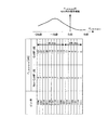
また、式(1)に示すPo_PUSCH,c(j)は、Po_NOMINAL_PUSCH,c(j)及びPo_UE_PUSCH,c(j)の2つのパラメータの加算値である。Po_NOMINAL_PUSCH,c(j)は、セル固有パラメータ(セル毎に設定される値。同一セル内の全端末が共通に用いる値)であり、−126〜24[dBm]の範囲をステップ幅1[dB]で通知される。一方、Po_UE_PUSCH,c(j)は、端末固有パラメータ(端末毎に設定される値)であり、−8〜7[dBm]の範囲をステップ幅1[dB]で通知される。例えば、図1に示すように、4ビットのビット列で表されるPo_UE_PUSCH,c(j)(図1では単に「Po_UE_PUSCH」と表す。以下同様である。)は基地局から端末へ通知される(例えば、非特許文献1参照)。 Further, Po_PUSCH, c (j) shown in Expression (1) is an addition value of two parameters Po_NOMINAL_PUSCH, c (j) and Po_UE_PUSCH, c (j). P o_NOMINAL_PUSCH, c (j) is a cell-specific parameter (value set for each cell. A value commonly used by all terminals in the same cell), and a range of −126 to 24 [dBm] is set to a step width of 1 [ [dB]. On the other hand, Po_UE_PUSCH, c (j) is a terminal-specific parameter (value set for each terminal), and a range of −8 to 7 [dBm] is notified with a step width of 1 [dB]. For example, as shown in FIG. 1, Po_UE_PUSCH, c (j) represented by a 4-bit bit string (represented simply as “ Po_UE_PUSCH ” in FIG. 1 and so on) is reported from the base station to the terminal. (See Non-Patent
また、式(1)に示すPo_PUSCH,c(j)及びαc(j)は、送信データのタイプに対応したj=0,1,2のそれぞれに対して値が設定される。送信データのタイプとしては、例えば、Dynamic schedulingが適用されたPUSCH送信、semi−persistent schedulingが適用されたPUSCH送信、又は、RACH responseのためのPUSCH送信などが挙げられる。In addition, values of Po_PUSCH, c (j) and α c (j) shown in Expression (1) are set for j = 0, 1, and 2 corresponding to the type of transmission data. Examples of the type of transmission data include PUSCH transmission to which dynamic scheduling is applied, PUSCH transmission to which semi-persistent scheduling is applied, or PUSCH transmission for RACH response.
上述したPUSCHの送信電力制御において、HetNet環境でのCoMP運用を考慮すると、マクロ基地局(Macro eNB)によって制御される端末(以下、マクロ端末(Macro UE)という)から、ピコ基地局(Pico eNB)によって制御される端末(以下、ピコ端末(Pico UE)という)への、上り回線信号の干渉(以下、上り回線干渉という)が問題となる。 In the transmission power control of the PUSCH described above, in consideration of CoMP operation in a HetNet environment, a terminal controlled by a macro base station (Macro eNB) (hereinafter referred to as a macro terminal (Macro UE)) from a pico base station (Pico eNB) ), The interference of uplink signals (hereinafter referred to as uplink interference) to terminals controlled by (hereinafter referred to as pico UEs) becomes a problem.
図2は、HetNet環境における上り回線干渉の一例を説明する図である。 FIG. 2 is a diagram for explaining an example of uplink interference in a HetNet environment.
図2に示すMacro UEの上り回線の送信電力(上り回線送信電力)には、Macro UEとServing cellであるMacro eNBとの間のパスロスを補償する電力が設定される。一方、図2に示すPico UEの上り回線送信電力には、Pico UEとPico eNBとの間のパスロスを補償する電力が設定される。ここで、図2に示すように、Macro UEが、マクロセルのセルエッジ付近の領域(以下、セルエッジ領域という)に位置する場合又はMacro eNBからの直接波が受信困難な場所(例えば、ビルなどの障害物の陰)に位置する場合などでは、Macro UEとMacro eNBとの間のパスロスが大きくなる。この場合、Macro UEに設定される上り回線送信電力は、Pico UEに設定される上り回線送信電力よりも大きくなることが想定される。よって、このような状況では、Macro UEから送信される上り回線信号がPico UEから送信される上り回線信号に対して、上り回線干渉を与える可能性がある。特に、図2に示すように、Macro UEがピコセル付近に位置する場合は、上り回線干渉の影響がより大きくなる。 The uplink transmission power (uplink transmission power) of Macro UE shown in FIG. 2 is set with power that compensates for a path loss between Macro UE and Macro eNB that is a serving cell. On the other hand, the power for compensating the path loss between the Pico UE and the Pico eNB is set in the uplink transmission power of the Pico UE shown in FIG. Here, as shown in FIG. 2, when the Macro UE is located in a region near the cell edge of the macro cell (hereinafter referred to as a cell edge region) or a location where a direct wave from the Macro eNB is difficult to receive (for example, a failure such as a building) In the case of being located behind the object, the path loss between the Macro UE and the Macro eNB increases. In this case, it is assumed that the uplink transmission power set for the Macro UE is larger than the uplink transmission power set for the Pico UE. Therefore, in such a situation, the uplink signal transmitted from the Macro UE may cause uplink interference to the uplink signal transmitted from the Pico UE. In particular, as shown in FIG. 2, when the Macro UE is located near a pico cell, the influence of uplink interference becomes larger.
このような、HetNet環境における上り回線干渉問題を解決するために、UL CoMPを適用する端末(以下、CoMP UEという)に対して、複数の受信ポイントのうち、パスロスが最小の受信ポイント(基地局)に向けた上り回線送信電力(当該受信ポイントとのパスロスを補償する電力)を設定することが検討されている。例えば、図2においてMacro eNB及びPico eNBが協調してMacro UEの上り回線信号を受信する場合、Macro UE(CoMP UE)の上り回線送信電力には、Pico UEとMacro UEとの間のパスロスを補償する電力が設定される。これにより、CoMP UEからピコセルへの干渉レベルを低減できるので、UL CoMP適用によるシステム性能改善効果の向上が期待できる。 In order to solve the uplink interference problem in the HetNet environment, a reception point (base station) having a minimum path loss among a plurality of reception points with respect to a terminal to which UL CoMP is applied (hereinafter referred to as CoMP UE). ) To set up uplink transmission power (power to compensate for path loss with the receiving point). For example, when Macro eNB and Pico eNB cooperatively receive an uplink signal of Macro UE in FIG. 2, the path loss between Pico UE and Macro UE is included in the uplink transmission power of Macro UE (CoMP UE). The power to be compensated is set. Thereby, since the interference level from CoMP UE to a pico cell can be reduced, the improvement of the system performance improvement effect by UL CoMP application can be expected.
従来のServing cell向けの上り回線送信電力を式(1)とすると、パスロスが最小の受信ポイントに向けた上り回線送信電力は式(2)で表される。
![]()
![]()
式(2)では、式(1)のパラメータに加えて、ΔPLが設定される。ΔPLは、端末における、複数受信ポイントとの間のパスロスレベルのうち最小のパスロスレベルと、Serving cellとの間のパスロスレベルと、の差(以下、パスロス差という)を示す。例えば、図2に示すMacro UEに設定されるΔPLは、Macro eNBとMacro UEとの間のパスロスレベルと、Pico eNBとMacro UEとの間のパスロスレベルとの差となる。In Expression (2), Δ PL is set in addition to the parameters of Expression (1). Δ PL indicates a difference (hereinafter referred to as a path loss difference) between the minimum path loss level among the path loss levels between the plurality of reception points and the path loss level between the serving cells in the terminal. For example, Δ PL set in the Macro UE illustrated in FIG. 2 is a difference between the path loss level between the Macro eNB and the Macro UE and the path loss level between the Pico eNB and the Macro UE.
パスロス差ΔPLは、Macro eNBとPico eNBとの送信電力差に依存する。例えば、非特許文献2には、パスロス差ΔPLは0〜−16[dB]の範囲の値を採りうることが開示されている。また、非特許文献3では、Po_UE_PUSCH,c(j)に加えて、CoMP UE用に送信電力を補正するための端末固有パラメータ(例えば、式(2)に示すパスロス差ΔPL)を新たに追加することが提案されている。The path loss difference Δ PL depends on the transmission power difference between the Macro eNB and the Pico eNB. For example,
しかしながら、非特許文献3のように、CoMP UE用に送信電力を補正するための端末固有パラメータ(例えば、パスロス差ΔPL)を新たに追加する場合、従来(Release 10)と比較して端末毎に通知するパラメータに要する通知ビット数(シグナリング量)が増加する課題がある。However, when a terminal-specific parameter (for example, path loss difference Δ PL ) for correcting transmission power for CoMP UE is newly added as in
本発明の目的は、シグナリング量の増加を抑えて、基地局から端末へ送信電力に関する制御値を通知することができる送信装置、受信装置及び送信電力制御方法を提供することを目的とする。 An object of the present invention is to provide a transmission apparatus, a reception apparatus, and a transmission power control method capable of notifying an increase in the amount of signaling and notifying a control value related to transmission power from a base station to a terminal.
本発明の一態様の送信装置は、受信装置から通知されたビット列、及び、前記ビット列の各々と送信電力に関する第1の制御値候補群及び第2の制御値候補群とがそれぞれ対応付けられた対応関係に基づいて、自機が複数の受信装置による協調受信の対象ではない場合、前記第1の制御値候補群のうち前記通知されたビット列に対応付けられた制御値候補を用い、自機が前記協調受信の対象である場合、前記第2の制御値候補群のうち前記通知されたビット列に対応付けられた制御値候補を用いて、送信電力を制御する制御手段と、前記送信電力を用いて信号を送信する送信手段と、を具備する構成を採る。 In the transmission device according to one aspect of the present invention, the bit sequence notified from the reception device, and each of the bit sequences and the first control value candidate group and the second control value candidate group related to transmission power are associated with each other. Based on the correspondence relationship, when the own device is not the target of cooperative reception by a plurality of receiving devices, the control device uses the control value candidate associated with the notified bit string in the first control value candidate group, and Is a target of the cooperative reception, a control means for controlling transmission power using a control value candidate associated with the notified bit string in the second control value candidate group, and the transmission power And a transmission means for transmitting a signal using the same.
本発明の一態様の受信装置は、ビット列の各々と送信装置の送信電力に関する第1の制御値候補群及び第2の制御値候補群とがそれぞれ対応付けられた対応関係に基づいて設定されたビット列を含む制御信号を生成する信号生成手段と、前記制御信号を送信する送信手段と、を具備し、前記送信装置が複数の受信装置による協調受信の対象ではない場合、前記第1の制御値候補群のうち前記設定されたビット列に対応付けられた制御値候補が用いられ、前記送信装置が前記協調受信の対象である場合、前記第2の制御値候補群のうち前記設定されたビット列に対応付けられた制御値候補が用いられる。 The reception device according to one aspect of the present invention is set based on a correspondence relationship in which each bit string and the first control value candidate group and the second control value candidate group related to the transmission power of the transmission device are associated with each other. A signal generating means for generating a control signal including a bit string; and a transmitting means for transmitting the control signal; and when the transmitting apparatus is not a target of cooperative reception by a plurality of receiving apparatuses, the first control value When a control value candidate associated with the set bit string is used in the candidate group, and the transmission apparatus is the target of the cooperative reception, the set bit string in the second control value candidate group is used. The associated control value candidate is used.
本発明の一態様の送信電力制御方法は、受信装置から通知されたビット列、及び、前記ビット列と送信電力に関する制御値との対応付けに基づいて、送信電力を制御する送信電力制御方法であって、前記対応付けでは、前記ビット列の各々と、第1の制御値候補群及び第2の制御値候補群と、がそれぞれ対応付けられ、送信装置が複数の受信装置による協調受信の対象ではない場合、前記第1の制御値候補群のうち、前記通知されたビット列に対応付けられた制御値候補を用いて送信電力を算出し、送信装置が前記協調受信の対象である場合、前記第2の制御値候補群のうち、前記通知されたビット列に対応付けられた制御値候補を用いて送信電力を算出する。 A transmission power control method according to an aspect of the present invention is a transmission power control method for controlling transmission power based on a bit string notified from a receiving apparatus and an association between the bit string and a control value related to transmission power. In the association, each of the bit strings is associated with the first control value candidate group and the second control value candidate group, respectively, and the transmission apparatus is not a target of cooperative reception by a plurality of reception apparatuses. When the transmission power is calculated using the control value candidate associated with the notified bit string in the first control value candidate group, and the transmission apparatus is the target of the cooperative reception, the second In the control value candidate group, the transmission power is calculated using the control value candidate associated with the notified bit string.
本発明によれば、シグナリング量の増加を抑えて、基地局から端末へ送信電力に関する制御値を通知することができる。 According to the present invention, it is possible to notify a control value related to transmission power from a base station to a terminal while suppressing an increase in signaling amount.
以下、本発明の実施の形態について図面を参照して詳細に説明する。なお、実施の形態において、同一の構成要素には同一の符号を付し、その説明は重複するので省略する。 Hereinafter, embodiments of the present invention will be described in detail with reference to the drawings. In the embodiment, the same components are denoted by the same reference numerals, and the description thereof will be omitted because it is duplicated.
[実施の形態1]
[通信システムの概要]
本発明の実施の形態1に係る通信システムは、送信装置と受信装置とを有する。特に、本実施の形態では、送信装置を端末100とし、受信装置を基地局200として説明する。この通信システムは、例えば、LTE−Advancedシステムである。そして、端末100は、例えば、LTE−Advancedシステムに対応する端末であり、基地局200は、例えば、LTE−Advancedシステムに対応する基地局である。また、例えば、端末100がUL CoMPを適用するCoMP UEとして動作する場合、端末100から送信された信号は、複数の基地局200によって協調して受信される。[Embodiment 1]
[Outline of communication system]
The communication system according to
図3は、本発明の実施の形態1に係る端末100の主要構成図である。図3に示す端末100において、制御部103は、基地局200から通知されたビット列(制御情報)に基づいて、送信電力を制御する。ここで、端末100がCoMP UEの場合、基地局200から通知されるビット列(制御情報)は、Non−CoMP UE向けの制御値候補群(第1の制御値候補群)の制御値候補が取り得る値の範囲、及び、CoMP時の送信電力の制御に関する制御値として取り得る値の範囲において設定された制御値に対応する。送信部114は、制御部103で算出された送信電力を用いてデータ信号(送信データ)を送信する。
FIG. 3 is a main configuration diagram of
図4は、本発明の実施の形態1に係る基地局200の主要構成図である。図4に示す基地局200において、信号生成部201は、端末100(送信装置)の送信電力に関する制御値を示すビット列を含む制御信号を生成する。ここで、端末100がCoMP UEの場合、信号生成部201が生成するビット列(制御情報)は、Non−CoMP UE向けの制御値候補群(第1の制御値候補群)の制御値候補が取り得る値の範囲、及び、CoMP時の送信電力の制御に関する制御値として取り得る値の範囲において設定された制御値に対応する。送信部205は、信号生成部201で生成された制御信号を送信する。
FIG. 4 is a main configuration diagram of
[端末100の構成]
図5は、本発明の実施の形態1に係る端末100の構成を示すブロック図である。[Configuration of terminal 100]
FIG. 5 is a block diagram showing a configuration of
端末100において、受信部101は、基地局200から送信された信号をアンテナを介して受信し、受信信号に対してダウンコンバート、A/D変換等の受信処理を施し、受信処理を施した受信信号を復調部102に出力する。受信信号には、送信電力制御に関する制御情報(例えば、式(1)に示す、基地局200から設定されるパラメータ)が含まれる。
In
復調部102は、受信部101から入力される受信信号のうち、送信電力制御に関する制御情報を復調し、復調した制御情報を制御部103(制御値算出部105及び送信電力制御部106)に出力する。また、復調部102は、受信信号のうち送信電力制御に直接関連しない制御情報(詳細は後述する)を制御部103(CoMP判定部104)に出力する。
制御部103は、基地局200から通知される制御情報(ビット列)に基づいて、端末100から送信される送信信号(上り回線信号)の送信電力を制御する。制御部103は、CoMP判定部104と、制御値算出部105と、送信電力制御部106とを有する。
The
CoMP判定部104は、復調部102から入力される制御情報に基づいて、端末100が、複数の基地局200による協調受信が適用される端末(CoMP UE)であるか否かを判定し、判定結果を制御値算出部105へ出力する。つまり、CoMP判定部104は、端末100がCoMPの対象ではない端末(Non−CoMP UE)であるか、CoMPの対象である端末(CoMP UE)であるかを判定する。
例えば、CoMP判定部104は、端末100に設定された制御情報に基づいて、端末100がCoMP UEであるかNon−CoMP UEであるかを暗示的に判定してもよい。例えば、端末100に設定された制御情報としては、UL CoMPを適用するために必要な端末固有の参照信号用系列グループ番号、端末固有の参照信号用系列番号、参照信号用系列グループ番号を得るための仮想のセルID(Virtual cell ID)が挙げられる。そして、CoMP判定部104は、上記制御情報が設定された端末100、又は、上記制御情報が設定可能な端末100であればCoMP UEと判定し、上記制御情報が設定されていない端末100、又は、上記制御情報が設定不可能な端末100であればNon−CoMP UEと判定する。
For example, the
または、CoMP判定部104は、自機向けの制御情報(例えば上記ビット列)を通知する基地局200(Serving cell)以外の基地局に向けて信号を送信する場合、端末100がCoMP UE(協調受信対象)であると判定し、自機向けの制御情報を通知する基地局200(Serving cell)に向けて信号を送信する場合、端末100がNon−CoMP UE(協調受信の対象ではない)と判定してもよい。
Alternatively, when the
また、端末100がCoMP UEであるか否かを示す情報が基地局200から端末100へ明示的に通知されてもよい。この場合、CoMP判定部104は当該情報に基づいて、端末100がCoMP UEであるかNon−CoMP UEであるかを判定する。
Also, information indicating whether the terminal 100 is a CoMP UE may be explicitly notified from the
制御値算出部105は、CoMP判定部104から入力される判定結果に応じて、復調部102から入力される送信電力制御に関する制御情報を用いて、送信電力の制御値を算出する。具体的には、制御値算出部105は、端末100がNon−CoMP UEである場合、送信電力制御に関する制御情報を、Non−CoMP UE用の制御情報として用いる。一方、制御値算出部105は、端末100がCoMP UEである場合、送信電力制御に関する制御情報を、CoMP UE用の制御情報として用いる。ここで、端末100がCoMP UEの場合、上記送信電力制御に関する制御情報(ビット列)は、Non−CoMP UE向けの制御値候補が取り得る値の範囲、及び、CoMP時の送信電力の制御に関する制御値として取り得る値の範囲において設定された制御値を示す。制御値算出部105は、算出した制御値を送信電力制御部106に出力する。
Control
送信電力の制御値として、例えば、式(1)に示すPo_PUSCH,c(j)の算出に用いられる端末固有パラメータであるPo_UE_PUSCH,c(j)が挙げられる。例えば、端末100がNon−CoMP UEの場合に基地局200から通知される送信電力制御に関する制御情報として、図1に示すようなPo_UE_PUSCH,c(j)に対応するビット列が挙げられる。一方、端末100がCoMP UEの場合に基地局200から通知される送信電力制御に関する制御情報(ビット列)に対応するPo_UE_PUSCH,c(j)には、従来のパスロスの推定誤差を補正するための値(例えば、図1に示す−8〜7dB)に加え、CoMP UEに対する最適な受信ポイント(パスロスがより小さい受信ポイント)向けの送信電力に補正するための値(例えば、式(2)に示すΔPLを考慮した値)が含まれる。本実施の形態における送信電力の制御値の詳細な説明については後述する。As a control value for transmission power, for example, P O - PUSCH shown in equation (1), P o_UE_PUSCH a terminal-specific parameters used in the calculation of c (j), c (j ) and the like. For example, as control information related to transmission power control notified from the
送信電力制御部106は、制御値算出部105から入力される送信電力の制御値(Po_UE_PUSCH,c(j))、及び、復調部102から入力される送信電力制御に関する制御情報(例えば、セル固有パラメータであるPo_NOMINAL_PUSCH,c(j))に基づいて、データ信号(PUSCH)の送信電力PPUSCH,c(j)を決定し、決定した送信電力を送信部114(増幅部116)に出力する。具体的には、送信電力制御部106は、セル固有パラメータPo_NOMINAL_PUSCH,c(j)と端末固有パラメータPo_UE_PUSCH,c(j)とを加算することで、Po_PUSCH,c(j)を導出する。そして、送信電力制御部106は、導出したPo_PUSCH,c(j)を用いて、式(1)に従ってデータ信号(PUSCH)の送信電力PPUSCH,c(j)を決定する。The transmission
信号生成部107は、入力される送信データに対して、設定されている送信方式に応じた信号生成処理を行う。例えば、送信方式がOFDM(Orthogonal Frequency Division Multiplexing)方式である場合、信号生成部107は、符号化部108と、変調部109と、DFT(Discrete Fourier Transform)部110と、マッピング部111と、IFFT(Inverse Fast Fourier Transform)部112と、CP(Cyclic Prefix)付加部113とを有する。ただし、送信方式はOFDM方式に限らず、信号生成部107は、設定された送信方式に応じた構成を採るものとする。
The signal generation unit 107 performs signal generation processing according to the set transmission method on the input transmission data. For example, when the transmission method is an OFDM (Orthogonal Frequency Division Multiplexing) method, the signal generation unit 107 includes an
符号化部108は、送信データを符号化して、符号化データを変調部109に出力し、変調部109は、符号化部108から入力される符号化データを変調して、変調データをDFT部110に出力する。
The
DFT部110は、変調部109から入力される変調データ信号にDFT処理を施して、マッピング部111に出力する。
The
マッピング部111は、基地局200から指示された周波数リソース割当情報(図示せず)に基づいて、DFT部110から入力されるDFT処理後のデータ信号を、周波数リソースにマッピングしてIFFT部112に出力する。
Based on frequency resource allocation information (not shown) instructed from
IFFT部112は、データ信号がマッピングされた複数のサブキャリアに対してIFFT処理を行い、IFFT処理後の信号をCP付加部113に出力する。
CP付加部113は、IFFT部112から入力されるIFFT後の信号の後尾部分と同じ信号をCPとして先頭に付加し、CP付加後の信号を送信部114(D/A部115)に出力する。
送信部114は、制御部103から入力される送信電力値(PPUSCH,c(j))を用いて、信号生成部107から入力される信号(PUSCH)に対して送信処理を行い、送信処理後の信号をアンテナを介して送信する。送信部114は、D/A部115と、増幅部116と、アップコンバート部117とを有する。The
D/A部115は、CP付加部113から入力される信号をD/A変換し、D/A変換後の信号を増幅部116に出力する。
The D / A unit 115 D / A converts the signal input from the
増幅部116は、送信電力制御部106から入力される送信電力に従って、D/A部115から入力される信号の送信電力を増幅し、増幅後の信号をアップコンバート部117に出力する。
Amplifying
アップコンバート部117は、増幅部116から入力される信号に対し、搬送波周波数への周波数変換を行う。アップコンバート部117は、送信処理後の信号をアンテナを介して送信する。
The up-
[基地局200の構成]
図6は、本発明の実施の形態1に係る基地局200の構成を示すブロック図である。[Configuration of Base Station 200]
FIG. 6 is a block diagram showing a configuration of
基地局200において、信号生成部201は、各端末100に対する送信電力制御に関する制御情報を生成し、生成した制御情報に対して信号生成処理を行う。信号生成部201は、パスロス差推定部202と、送信電力制御情報生成部203と、変調部204と、を有する。
In
パスロス差推定部202は、端末100と基地局200との間のパスロスと、端末100と各受信ポイントとの間のパスロスのうち最も小さいパスロスと、の差(パスロス差:ΔPL)を推定し、推定したパスロス差を送信電力制御情報生成部203に出力する。The path loss
例えば、端末100が送信する上り回線信号(PUSCH、SRS(Sounding Reference Signal)又はPRACH(Physical Random Access Channel)など)の受信レベル(RSRP:Reference Signal Received Power)が複数の受信ポイントで同時に測定され、基地局200(CoMPが適用されるエリア内のスケジューラ(図示せず))が測定結果を複数の受信ポイントから受け取ってもよい。そして、パスロス差推定部202は、測定結果の差分を求めることで上記パスロス差を導出してもよい。又は、パスロス差推定部202は、端末100がServing cellへ定期的に報告する、隣接セル(複数の受信ポイント)からの参照信号の受信レベル(RSRP)を用いて、パスロス差を導出してもよい。
For example, the reception level (RSRP: Reference Signal Received Power) of the uplink signal (such as PUSCH, SRS (Sounding Reference Signal) or PRACH (Physical Random Access Channel)) transmitted by the terminal 100 is simultaneously measured at a plurality of reception points, Base station 200 (scheduler (not shown) in an area to which CoMP is applied) may receive measurement results from a plurality of reception points. And the path loss
送信電力制御情報生成部203は、端末100の送信電力制御に関する制御情報を生成し、生成した制御情報を変調部204へ出力する。具体的には、送信電力制御情報生成部203は、端末100の受信品質に基づいて、端末100に適した送信電力を決定し、式(1)に示す、基地局200が設定するパラメータ(端末固有パラメータPo_UE_PUSCH,c(j)を含む)を生成する。ただし、送信電力制御情報生成部203は、端末100がNon−CoMP UEの場合、Serving cell向けの送信電力となるように、端末固有パラメータPo_UE_PUSCH,c(j)[dB]を決定する。一方、送信電力制御情報生成部203は、端末100がCoMP UEの場合、パスロスが最小の受信ポイント向けの送信電力となるように、パスロス差推定部202から入力されるパスロス差を用いて、端末固有パラメータPo_UE_PUSCH,c(j)[dB]を決定する。Transmission power control
変調部204は、送信電力制御情報生成部203から出力された送信電力制御に関する制御情報を変調して、送信部205に出力する。
送信部205は、変調部204から入力される信号に対してD/A変換、アップコンバート、増幅等の送信処理を施し、送信処理を施した信号をアンテナを介して送信する。
The
一方、受信部206は、端末から送信された信号をアンテナを介して受信し、受信信号に対してダウンコンバート、A/D変換等の受信処理を施し、受信処理を施した受信信号をCP除去部208に出力する。
On the other hand, the
信号処理部207は、受信部206から入力される受信信号に対して、設定されている送信方式に応じた信号生成処理を行う。例えば、送信方式がOFDM方式である場合、信号処理部207は、CP除去部208と、FFT(Fast Fourier Transform)部209と、デマッピング部210と、周波数領域等化部211と、IDFT(Inverse Discrete Fourier Transform)部212と、復調部213と、復号部214とを有する。ただし、送信方式はOFDM方式に限らず、信号処理部207は、設定された送信方式に応じた構成を採るものとする。
The signal processing unit 207 performs signal generation processing corresponding to the set transmission method on the reception signal input from the
CP除去部208は、受信部206から入力される受信信号の先頭に付加されたCPを除去して、FFT部209に出力し、FFT部209は、CP除去部208から入力される受信信号に対してFFT処理を施して周波数領域の信号に変換し、周波数領域に変換した信号をデマッピング部210に出力する。
抽出手段としてのデマッピング部210は、端末100の送信帯域に対応する信号を抽出し、抽出した信号を周波数領域等化部211に出力する。
The
周波数領域等化部211は、デマッピング部210から入力される信号に対して等化処理を施して、IDFT部212に出力し、IDFT部212は、周波数領域等化部211から入力される信号に対してIDFT処理を施して、復調部213に出力する。
The frequency
復調部213は、IDFT部212から入力される信号に対して復調処理を施して、復号部214に出力し、復号部214は、復調部213から入力される信号に対して復号処理を施し、受信データを抽出する。
[端末100及び基地局200の動作]
以上の構成を有する端末100及び基地局200の動作について説明する。[Operations of
Operations of the terminal 100 and the
例えば、式(2)において、仮に、Serving cell向けの送信電力制御に用いられるPo_PUSCH,c(j)をPo_PUSCH,c,serving(j)とし、パスロスが最小の受信ポイント向けの送信電力制御に用いられるPo_PUSCH,c(j)をPo_PUSCH,c,min(j)とする。この場合、Po_PUSCH,c,serving(j)とPo_PUSCH,c,min(j)との間には次式(3)に示す関係が成り立つ。
![]()
![]()
すなわち、Po_PUSCH,c,serving(j)をαc(j)・ΔPLだけ小さい値に変更することで、Po_PUSCH,c,min(j)が得られる。つまり、基地局200から端末100へ通知されるパラメータである従来のPo_PUSCH,c(j)(Serving cell向けの送信電力制御に関する制御値)をαc(j)・ΔPLだけ小さい値に変更することで、CoMP UE向けの送信電力制御が実施可能となる。 That, P o_PUSCH, c, by changing serving the (j) to a value smaller by α c (j) · Δ PL , P o_PUSCH, c, min (j) is obtained. That is, the conventional Po_PUSCH, c (j) (control value related to transmission power control for the serving cell) , which is a parameter notified from the
ここで、パスロス差ΔPLは端末100の位置に依存して決まる。つまり、パスロス差ΔPLは端末固有パラメータであると言える。また、上述したように、式(2)に示すPo_PUSCH,c(j)(式(3)に示すPo_PUSCH,c,serving(j)に相当)は、セル固有パラメータPo_NOMINAL_PUSCH,c(j)及び端末固有パラメータPo_UE_PUSCH,c(j)の2つのパラメータで表される。Here, the path loss difference Δ PL is determined depending on the position of the terminal 100. That is, the path loss difference delta PL can be said to be terminal-specific parameter. Further, as described above, Po_PUSCH, c (j) shown in Expression (2) (corresponding to Po_PUSCH, c, serving (j) shown in Expression (3)) is the cell-specific parameter Po_NOMINAL_PUSCH, c (j ) And terminal-specific parameter P o_UE_PUSCH, c (j).
よって、Po_PUSCH,c(j)の変更(Po_PUSCH,c,serving(j)からPo_PUSCH,c,min(j)への変更)は、端末固有パラメータであるPo_UE_PUSCH,c(j)を用いて基地局200から端末100へ通知することができる。具体的には、端末固有パラメータであるPo_UE_PUSCH,c(j)として、式(3)に示すPo_PUSCH,c,serving(j)、及び、パスロス差ΔPLの双方を考慮した値を端末100毎に設定することが可能である。Therefore, the change of Po_PUSCH, c (j) (change from Po_PUSCH, c, serving (j) to Po_PUSCH, c, min (j)) changes the terminal-specific parameter Po_UE_PUSCH, c (j). It is possible to notify the terminal 100 from the
従来のPo_UE_PUSCH,c(j)(−8〜7[dB]。例えば、図1参照)の通知は、端末100におけるパスロスの測定誤差を補正する目的がある。一方、パスロスの測定誤差を補正する目的に加え、上述したパスロス差ΔPLを考慮したCoMP UEの送信電力への変更を目的として、Po_UE_PUSCH,c(j)の通知を行う場合には、双方の目的を考慮した範囲のPo_UE_PUSCH,c(j)が設定される必要がある。例えば、パスロスの測定誤差の補正範囲として、図1に示す−8〜7[dB]を想定し、パスロス差ΔPLの範囲として0〜−16[dB]を想定した場合、パスロス差ΔPLも考慮されたPo_UE_PUSCH,c(j)の設定範囲は、−24〜7[dB]となる。The conventional notification of Po_UE_PUSCH, c (j) (−8 to 7 [dB], see FIG. 1, for example) has the purpose of correcting a path loss measurement error in the
このように、CoMP UE向けの送信電力に関する制御値であるPo_UE_PUSCH,c(j)の各候補は、Non−CoMP向けの送信電力に関する制御値である従来のPo_UE_PUSCH,c(j)が取り得る値の範囲(−8〜7[dB])、及び、CoMP時の送信電力の制御に関する制御値として取り得る値の範囲(−24〜7[dB])において設定される。In this way, each candidate of Po_UE_PUSCH, c (j) , which is a control value related to transmission power for CoMP UE, is taken by conventional Po_UE_PUSCH, c (j) , which is a control value related to transmission power for Non-CoMP. It is set within a range of values (−8 to 7 [dB]) to be obtained and a range of values (−24 to 7 [dB]) that can be taken as control values related to transmission power control during CoMP.
次に、パスロス差ΔPLを考慮したPo_UE_PUSCH,c(j)を通知する場合と、式(2)に示すPo_UE_PUSCH,c(j)及びΔPLを個別に通知する場合とを比較する。Po_UE_PUSCH,c(j)及びΔPLを個別に通知する場合、Po_UE_PUSCH,c(j)(−8〜7[dB])の通知のための4ビット(図1参照)、及び、パスロス差ΔPL(0〜−16[dB])の通知のための5ビットの合計9ビットが必要となる。一方、パスロス差ΔPLを考慮したPo_UE_PUSCH,c(j)を通知する場合、Po_UE_PUSCH,c(j)(−24〜7[dB])の通知のための5ビットが必要となる。つまり、Po_UE_PUSCH,c(j)に加えて新たな端末固有パラメータであるΔPLを追加で通知する場合よりも、パスロス差ΔPLを考慮したPo_UE_PUSCH,c(j)を設定して通知することにより、通知ビット数(シグナリング量)を削減することができる。Then, comparing path loss difference delta P considering PL O_UE_PUSCH, in the case of notifying the c (j), P O_UE_PUSCH shown in Equation (2), and a case of notifying c a (j) and delta PL individually. P O_UE_PUSCH, when notifying individually c (j) and Δ PL, P o_UE_PUSCH, c ( j) (- 8~7 [dB]) of the
つまり、本実施の形態によれば、従来のPo_UE_PUSCH,c(j)の通知に要するシグナリング量(図1では4ビット)からのシグナリング量の増加を抑えて、CoMP UEに対する送信電力に関する制御値を、基地局200から端末100へ通知することができる。That is, according to the present embodiment, the control value related to the transmission power for the CoMP UE is suppressed while suppressing an increase in the signaling amount from the signaling amount (4 bits in FIG. 1) required for the conventional notification of Po_UE_PUSCH, c (j). Can be notified from the
[実施の形態2]
実施の形態1では、新たな端末固有パラメータであるΔPLを追加で通知することなく、パスロス差ΔPLを考慮したPo_UE_PUSCH,c(j)を通知する場合について説明した。ただし、この場合、従来(Release 10又はLTE)のシグナリングフォーマットからLTE−Advanced(Release 11)向けのシグナリングフォーマットへの変更が必要になる。しかし、LTE−Advanced(Release 11)では、システムの複雑さの観点より、従来(Release 10)のシグナリングフォーマットからの変更が無いことがより望ましい。[Embodiment 2]
In the first embodiment, without notifying an additional a new terminal-specific parameter delta PL, P O_UE_PUSCH considering path loss difference delta PL, has been described a case of notifying the c (j). However, in this case, it is necessary to change from a conventional (
そこで、本実施の形態では、上記対応付けルールにおいて、Non−CoMP UEとCoMP UEとの間でビット列と制御値(Po_UE_PUSCH,c(j))との対応関係を互いに異ならせる。Therefore, in the present embodiment, in the association rule, the correspondence relationship between the bit string and the control value ( Po_UE_PUSCH, c (j)) is different between the Non-CoMP UE and the CoMP UE.
なお、本実施の形態に係る基地局及び端末は、実施の形態1に係る端末100及び基地局200と基本構成が共通するので、図3〜図6を援用して説明する。
The base station and terminal according to the present embodiment have the same basic configuration as
[端末100及び基地局200の主要構成]
図3は、本発明の実施の形態2に係る端末100の主要構成図である。図3に示す端末100において、制御部103は、基地局200から通知されたビット列(制御情報)、及び、ビット列と送信電力に関する制御値との対応付けに基づいて、送信電力を制御する。上記対応付けでは、ビット列の各々と、Non−CoMP UE向けの制御値候補群(第1の制御値候補群)及びCoMP UE向けの制御値候補群(第2の制御値候補群)と、がそれぞれ対応付けられている。制御部103は、端末100(自機)が複数の基地局200によるCoMP(協調受信)の対象ではない場合、Non−CoMP向けの制御値候補群のうち、通知されたビット列に対応付けられた制御値候補を用いて送信電力を算出し、端末100がCoMPの対象である場合、CoMP向けの制御値候補群のうち、通知されたビット列に対応付けられた制御値候補を用いて送信電力を算出する。[Main configuration of
FIG. 3 is a main configuration diagram of
図4は、本発明の実施の形態2に係る基地局200の主要構成図である。図4に示す基地局200において、信号生成部201は、ビット列の各々と端末100(送信装置)の送信電力に関するNon−CoMP UE向けの制御値候補群(第1の制御値候補群)及びCoMP UE向けの制御値候補群(第2の制御値候補群)とがそれぞれ対応付けられた対応関係に基づいて設定されたビット列を含む制御信号を生成する。信号生成部201では、端末100が複数の基地局200によるCoMP(協調受信)の対象ではない場合、Non−CoMP UE向けの制御値候補群のうち、設定されたビット列に対応付けられた制御値候補が用いられ、端末100がCoMPの対象である場合、CoMP UE向けの制御値候補群のうち、設定されたビット列に対応付けられた制御値候補が用いられる。
FIG. 4 is a main configuration diagram of
[端末100及び基地局200の構成]
図5に示す端末100において、制御値算出部105は、送信電力制御に関する制御情報(ビット列)と上記送信電力の制御値(Po_UE_PUSCH,c(j):dB値)との対応付けルールを参照して、当該制御情報(ビット列)に対応する送信電力の制御値(dB値)を算出する。ここで、上記対応付けルールは、端末100と基地局200との間で予め共有されている。また、上記対応付けルールには、端末100がCoMP UEであるかNon−CoMP UEであるかによって、同一ビット列に対して異なる制御値が対応付けられている。上記対応付けルールの詳細な説明については後述する。[Configuration of
In
図6に示す基地局200において、、送信電力制御情報生成部203は、送信電力制御に関する制御情報(ビット列)と送信電力の制御値であるPo_UE_PUSCH,c(j)(dB値)との対応付けルールを用いて、決定した端末固有パラメータPo_UE_PUSCH,c(j)(dB値)をビット列に変換する。上記対応付けルールは、端末100と基地局200との間で予め共有している。上記対応付けルールの詳細な説明については後述する。In
次に、端末100の制御値算出部105及び基地局200の送信電力制御情報生成部203で用いられる、制御情報(ビット列)とPo_UE_PUSCH,c(j)(dB値)との対応付けルールについて説明する。Next, associating rules between control information (bit string) and Po_UE_PUSCH, c (j) (dB value) used in control
具体的には、対応付けルールでは、ビット列の各々と、Non−CoMP UE向けのPo_UE_PUSCH,c(j)及びCoMP UE向けのPo_UE_PUSCH,c(j)の2種類の値と、がそれぞれ対応付けられる。なお、Non−CoMP UE向けのPo_UE_PUSCH,c(j)は、従来(例えば図1)と同様の範囲(−8〜7[dB])が設定され、CoMP UE向けのPo_UE_PUSCH,c(j)は、従来の通知範囲に加えて、パスロス差ΔPLを考慮した範囲(−24〜7[dB])が設定される。Specifically, the association rules, and each bit string, and two values of Non-CoMP UE for the P o_UE_PUSCH, c (j) and CoMP UE for the P o_UE_PUSCH, c (j), but correspond Attached. Incidentally, Non-CoMP UE for the P O_UE_PUSCH, c (j) is conventionally (e.g., FIG. 1) and the same range (-8 to 7 [dB]) is set, CoMP UE for the P O_UE_PUSCH, c (j ), in addition to the conventional notification range, the range in consideration of the path loss difference Δ PL (-24~7 [dB]) is set.
図7は、本実施の形態における制御情報(ビット列)とPo_UE_PUSCH,c(j)との対応付けの一例を示す。図7に示すように、ビット列の長さは4ビット(0000〜1111)の固定値であり、当該ビット列で通知可能なPo_UE_PUSCH,c(j)は16種類である。FIG. 7 shows an example of correspondence between control information (bit string) and Po_UE_PUSCH, c (j) in the present embodiment. As shown in FIG. 7, the length of the bit string is a fixed value of 4 bits (0000 to 1111), and there are 16 types of Po_UE_PUSCH, c (j) that can be notified by the bit string.
図7に示すように、Non−CoMP UE向けのPo_UE_PUSCH,c(j)として、−8〜7[dB]の範囲のうち16値が設定される。すなわち、Non−CoMP UE向けのPo_UE_PUSCH,c(j)として、−8〜7[dB]の値が1dB間隔で設定される(ステップ幅:1[dB])。一方、CoMP UE向けのPo_UE_PUSCH,c(j)として、−23〜7[dB]の範囲のうち16値が設定される。すなわち、Non−CoMP UE向けのPo_UE_PUSCH,c(j)として、−23〜7[dB]の値が2dB間隔で設定される(ステップ幅:2[dB])。As illustrated in FIG. 7, 16 values in a range of −8 to 7 [dB] are set as Po_UE_PUSCH, c (j) for Non-CoMP UE. That is, as Po_UE_PUSCH, c (j) for Non-CoMP UE, a value of −8 to 7 [dB] is set at 1 dB intervals (step width: 1 [dB]). On the other hand, 16 values in the range of −23 to 7 [dB] are set as Po_UE_PUSCH, c (j) for CoMP UE. That is, a value of −23 to 7 [dB] is set at 2 dB intervals as Po_UE_PUSCH, c (j) for Non-CoMP UE (step width: 2 [dB]).
すなわち、図7に示すように、CoMP UE向けのPo_UE_PUSCH,c(j)における隣接する制御値間の間隔(ステップ幅)は、Non−CoMP UE向けのPo_UE_PUSCH,c(j)における隣接する制御値間の間隔(ステップ幅)よりも大きい(粗い)。これにより、CoMP UEに対して、Non−CoMP UEの場合と同一のビット数(図7では4ビット)のビット列を用いて、Po_UE_PUSCH,c(j)の通知範囲を拡張することが可能となる。つまり、図7に示すように、CoMP UE向けのPo_UE_PUSCH,c(j)における最大値(7[dB])と最小値(−23[dB])との差は、Non−CoMP UE向けのPo_UE_PUSCH,c(j)における最大値(7[dB])と最小値(−8[dB])との差よりも大きい。That is, as shown in FIG. 7, CoMP UE for the P O_UE_PUSCH, the spacing between adjacent control values in c (j) (step width), adjacent in the Non-CoMP UE for the P o_UE_PUSCH, c (j) Larger (rougher) than the interval (step width) between control values. Thereby, it is possible to extend the notification range of Po_UE_PUSCH, c (j) to the CoMP UE using a bit string having the same number of bits as in the case of the Non-CoMP UE (4 bits in FIG. 7). Become. That is, as shown in FIG. 7, the difference between the maximum value (7 [dB]) and the minimum value (−23 [dB]) in Po_UE_PUSCH, c (j) for CoMP UE is the same for Non-CoMP UE. It is larger than the difference between the maximum value (7 [dB]) and the minimum value (−8 [dB]) in Po_UE_PUSCH, c (j).
よって、基地局200の送信電力制御情報生成部203は、端末100がNon−CoMP UEであるかCoMP UEであるかに応じて、同一の制御情報(ビット列)を用いて互いに異なるPo_UE_PUSCH,c(j)を設定することができる。つまり、基地局200は、同一の制御情報を用いて、端末100がNon−CoMP UE又はCoMP UEの双方の場合における最適な送信電力を指示することが可能となる。例えば、図7では、送信電力制御情報生成部203は、Non−CoMP UE向けのPo_UE_PUSCH,c(j)=−8[dB]と、CoMP UE向けのPo_UE_PUSCH,c(j)=−23[dB]と、を同一ビット列「0000」として設定することができる。Therefore, the transmission power control
また、端末100の制御値算出部105は、端末100がNon−CoMP UEであるかCoMP UEであるかに応じて、基地局200から通知される制御情報(ビット列)に対応するPo_UE_PUSCH,c(j)を読み替えることにより、Non−CoMP UE及びCoMP UEの双方の送信電力の制御値を適切に特定することができる。例えば、図7では、制御値算出部105は、ビット列「0000」が通知された場合、端末100がNon−CoMP UEであれば、Po_UE_PUSCH,c(j)=−8[dB]と特定し、端末100がCoMP UEであれば、Po_UE_PUSCH,c(j)=−23[dB]と特定する。Further, the control
このように、端末100は、端末100がCoMP UEではない場合、Non−CoMP UE向けのPo_UE_PUSCH,c(j)のうち、通知されたビット列に対応付けられたPo_UE_PUSCH,c(j)を用いて送信電力を算出し、端末100がCoMP UEである場合、CoMP UE向けのPo_UE_PUSCH,c(j)のうち、通知されたビット列に対応付けられたPo_UE_PUSCH,c(j)を用いて送信電力を算出する。Thus, the terminal 100, when the terminal 100 is not a CoMP UE, Non-CoMP UE for the P O_UE_PUSCH, among c (j), P O_UE_PUSCH associated with notification bit string, c a (j) used to calculate the transmission power, if the terminal 100 is CoMP UE, CoMP UE for the P O_UE_PUSCH, among c (j), P o_UE_PUSCH associated with notification bit string, using c (j) Calculate the transmission power.
こうすることで、本実施の形態におけるPo_UE_PUSCH,c(j)の通知(図7)では、従来のPo_UE_PUSCH,c(j)の通知(図1)と比較して、シグナリング量が増加しない。すなわち、シグナリング量を増加させることなく、基地局200から端末100へ送信電力に関する制御値を通知することができる。また、本実施の形態におけるPo_UE_PUSCH,c(j)の通知(図7)では、従来のPo_UE_PUSCH,c(j)の通知(図1)と比較して、シグナリングフォーマットの変更が不要となり、シグナリングフォーマットの変更によってシステムが複雑になることを回避することができる。By doing so, the amount of signaling does not increase in the notification of Po_UE_PUSCH, c (j) in this embodiment (FIG. 7) compared to the conventional notification of Po_UE_PUSCH, c (j) (FIG. 1). . That is, the control value regarding the transmission power can be notified from the
つまり、本実施の形態によれば、従来のPo_UE_PUSCH,c(j)の通知(図1)と比較して、シグナリングフォーマットを変更することなく、かつ、シグナリング量を増加させることなく、CoMP UEに対する送信電力制御を行うことで、UL CoMPによるシステム性能改善効果を得ることができる。That is, according to the present embodiment, compared with the conventional notification of Po_UE_PUSCH, c (j) (FIG. 1), the CoMP UE does not change the signaling format and increases the signaling amount. By performing transmission power control on the system, it is possible to obtain a system performance improvement effect by UL CoMP.
なお、送信電力の設定誤差は、上り回線の割当制御情報(UL grant)に含まれるTPCコマンド(式(1)に示すfc(i))を用いても補正可能であるが、TPCコマンドを用いる方法は効率が悪い。例えば、式(1)に示すfc(i)は、+3dB、+1dB、0dB、−1dBの値が設定可能であるので、3dBより大きな値を補正するためには複数回のUL grant送信が必要となるので、シグナリング量が増加してしまう。さらに、端末の上り回線の送信モードが変更された場合には、TPCコマンドの累計値がリセットされる。このため、送信モードが変更されるたびに複数回のUL grant送信による送信電力補正が必要となるので、オーバーヘッドが更に増加してしまう。これに対して、本実施の形態では、CoMP UEに対する端末固有パラメータであるPo_UE_PUSCH,c(j)の通知範囲を拡張することにより、適切な送信電力が設定される。こうすることで、上述したような複数回のUL grant送信の発生を回避することができる。The transmission power setting error can be corrected using a TPC command (f c (i) shown in Expression (1)) included in uplink allocation control information (UL grant). The method used is inefficient. For example, since f c (i) shown in the equation (1) can be set to +3 dB, +1 dB, 0 dB, and −1 dB, it is necessary to transmit a plurality of UL grants in order to correct a value larger than 3 dB. As a result, the amount of signaling increases. Further, when the uplink transmission mode of the terminal is changed, the cumulative value of the TPC command is reset. For this reason, each time the transmission mode is changed, transmission power correction by a plurality of UL grant transmissions is required, which further increases overhead. On the other hand, in this embodiment, appropriate transmission power is set by extending the notification range of Po_UE_PUSCH, c (j) , which is a terminal-specific parameter for CoMP UE. By doing so, the occurrence of multiple UL grant transmissions as described above can be avoided.
[実施の形態3]
本実施の形態では、Po_PUSCH,c(j)の変更を考慮したPo_UE_PUSCH,c(j)(つまり、CoMP UE向けのPo_UE_PUSCH,c(j))の各候補値の使用頻度、つまり、基地局200がセル内の端末100へ通知する頻度に着目する。[Embodiment 3]
In this embodiment, P O - PUSCH, c P considering changes (j) o_UE_PUSCH, c (j ) ( i.e., CoMP UE for the P o_UE_PUSCH, c (j)) the frequency of use of each candidate values of, that is, Attention is paid to the frequency at which the
なお、本実施の形態に係る基地局及び端末は、実施の形態2に係る端末100及び基地局200と基本構成が共通するので、図5,6を援用して説明する。
The base station and terminal according to the present embodiment have the same basic configuration as
上述したように、CoMP UE向けのPo_UE_PUSCH,c(j)の用途は2つある。As described above, there are two uses of Po_UE_PUSCH, c (j) for CoMP UE.
1つ目の用途は、従来(Non−CoMP UE)と同様、端末100(UE)におけるパスロスの測定誤差を補正することである。この場合、Po_UE_PUSCH,c(j)として想定される値の範囲は−8〜7[dB]であり(例えば図1参照)、Po_UE_PUSCH,c(j)の使用頻度は、0[dB]を中心としてプラス方向及びマイナス方向にガウス分布することが予想される。The first use is to correct a path loss measurement error in the terminal 100 (UE) as in the conventional case (Non-CoMP UE). In this case, the range of values assumed as Po_UE_PUSCH, c (j) is −8 to 7 [dB] (see, for example, FIG. 1), and the usage frequency of Po_UE_PUSCH, c (j) is 0 [dB]. A Gaussian distribution is expected in the positive direction and the negative direction with respect to.
2つ目の用途は、Serving cell向けの送信電力からパスロスが最小の受信ポイント向けの送信電力(CoMP UEの送信電力)への切替のために、送信電力を補正することである。この場合、Po_UE_PUSCH,c(j)は、パスロス差ΔPLに応じて、Serving cell向けの送信電力を低下させるために用いられる(例えば、式(3)参照)。そのため、ΔPLの使用頻度は、0[dB]よりもマイナス方向(例えば、−16〜0[dB])に分布することが予想される。The second application is to correct the transmission power for switching from the transmission power for the serving cell to the transmission power for the reception point with the smallest path loss (transmission power of the CoMP UE). In this case, P O_UE_PUSCH, c (j), depending on the path loss difference delta PL, used to reduce the transmission power for Serving cell (e.g., equation (3) refer). Therefore, the frequency of use of delta PL is, 0 [dB] minus direction than (e.g., -16~0 [dB]) is expected to be distributed to.
よって、上記2つの用途の双方を考慮すると、CoMP UE向けのPo_UE_PUSCH,c(j)の使用頻度は、図8に示すように、0[dB]よりもマイナス方向の領域において最も高くなることが予想される。すなわち、図8に示すように、CoMP UE向けのPo_UE_PUSCH,c(j)の使用頻度は、dB値において、マイナス方向の領域の方がプラス方向の領域よりも高くなる傾向がある。Therefore, in consideration of both of the above two applications, the usage frequency of Po_UE_PUSCH, c (j) for CoMP UE is the highest in the negative direction region than 0 [dB] as shown in FIG. Is expected. That is, as shown in FIG. 8, the usage frequency of Po_UE_PUSCH, c (j) for CoMP UE tends to be higher in the negative direction region than in the positive direction in the dB value.
そこで、本実施の形態では、CoMP UE向けのPo_UE_PUSCH,c(j)の使用頻度に応じて、Po_UE_PUSCH,c(j)の設定間隔(ステップ幅)を異ならせる。Therefore, in the present embodiment, the setting interval (step width) of Po_UE_PUSCH, c (j) is varied according to the usage frequency of Po_UE_PUSCH, c (j) for CoMP UE.
以下、端末100の制御値算出部105及び基地局200の送信電力制御情報生成部203で用いられる、制御情報(ビット列)とPo_UE_PUSCH,c(j)(dB値)との対応付けルールについて説明する。Hereinafter, an association rule between control information (bit string) and Po_UE_PUSCH, c (j) (dB value) used in control
図9は、本実施の形態における制御情報(ビット列)とPo_UE_PUSCH,c(j)との対応付けの一例を示す。FIG. 9 shows an example of correspondence between control information (bit string) and Po_UE_PUSCH, c (j) in the present embodiment.
図9に示すように、ビット列の長さは、実施の形態2(図7)と同様、4ビット(0000〜1111)の固定値であり、当該ビット列で通知可能なPo_UE_PUSCH,c(j)は16種類である。また、図9に示すように、Non−CoMP UE向けのPo_UE_PUSCH,c(j)として、実施の形態2と同様、−8〜7[dB]の値がステップ幅1[dB]で設定される。As shown in FIG. 9, the length of the bit string is a fixed value of 4 bits (0000 to 1111) as in Embodiment 2 (FIG. 7), and Po_UE_PUSCH, c (j) that can be notified by the bit string There are 16 types. Also, as shown in FIG. 9, as in Po-UE_PUSCH , c (j) for Non-CoMP UE, a value of −8 to 7 [dB] is set with a step width of 1 [dB], as in the second embodiment. The
また、図9に示すように、CoMP UE向けのPo_UE_PUSCH,c(j)として、−24〜7[dB]の値が設定される。ただし、図9に示すように、CoMP UE向けのPo_UE_PUSCH,c(j)のうち、−18〜−11[dB]の範囲では値が1dB間隔で設定される(ステップ幅:1[dB])。これに対して、図9に示すように、CoMP UE向けのPo_UE_PUSCH,c(j)のうち、−24〜−18[dB]の範囲、及び、−8〜7[dB]の範囲では、値が3dB間隔で設定される(ステップ幅:3[dB])。Also, as shown in FIG. 9, a value of −24 to 7 [dB] is set as Po_UE_PUSCH, c (j) for CoMP UE. However, as shown in FIG. 9, among Po_UE_PUSCH, c (j) for CoMP UE, values are set at 1 dB intervals in the range of −18 to −11 [dB] (step width: 1 [dB]). ). On the other hand, as shown in FIG. 9, in the Po_UE_PUSCH, c (j) for CoMP UE, in the range of −24 to −18 [dB] and in the range of −8 to 7 [dB], Values are set at 3 dB intervals (step width: 3 [dB]).
すなわち、図9に示すように、CoMP UE向けのPo_UE_PUSCH,c(j)の設定範囲(−24〜7[dB])において、セル内での使用頻度がより高い値を含む範囲(図9では−18〜−11[dB])では、より細かいステップ幅(1[dB])の値が設定され、隣接する制御値間の間隔がより小さくなる。一方、図9に示すように、CoMP UE向けのPo_UE_PUSCH,c(j)の設定範囲(−24〜7[dB])において、セル内での使用頻度がより低い値を含む領域(−24〜−18[dB]、又は、−11〜7[dB])では、より粗いステップ幅(3[dB])の値が設定され、隣接する制御値間の間隔がより大きくなる。That is, as shown in FIG. 9, in the setting range (−24 to 7 [dB]) of Po_UE_PUSCH, c (j) for CoMP UE, a range including a value with a higher usage frequency in the cell (FIG. 9). In -18 to -11 [dB]), a finer step width (1 [dB]) value is set, and the interval between adjacent control values becomes smaller. On the other hand, as shown in FIG. 9, in the setting range (−24 to 7 [dB]) of Po_UE_PUSCH, c (j) for CoMP UE, an area (−24) that includes a value that is less frequently used in the cell. ~ -18 [dB] or -11 to 7 [dB]), a coarser step width (3 [dB]) value is set, and the interval between adjacent control values becomes larger.
こうすることで、CoMP UE向けのPo_UE_PUSCH,c(j)の設定範囲のうち、使用頻度が高い範囲では、CoMP UE向けのPo_UE_PUSCH,c(j)として使用可能な値が細かく設定されるので、基地局200は、端末100に対して送信電力を高精度に設定することができる。すなわち、CoMP UEに対する送信電力の設定誤差によるシステム性能改善効果の低下を抑えることが可能となる。In this way, among the setting range of CoMP UE for the P o_UE_PUSCH, c (j), the frequently used range, CoMP UE for the P O_UE_PUSCH, usable value as c (j) is finely set Therefore, the
また、使用頻度が低い範囲では、CoMP UE向けのPo_UE_PUSCH,c(j)として使用可能な値が粗く設定されるので、使用頻度が高い範囲と比較して送信電力の設定誤差が発生しやすくなる。ただし、送信電力の設定誤差は、上り回線割当制御情報(UL grant)に含まれるTPCコマンド(式(1)に示すfc(i))を用いても補正可能である。例えば、式(1)に示すfc(i)は、+3dB、+1dB、0dB、−1dBの値が設定可能であるので、図9に示すステップ幅が粗い範囲(ステップ幅:3[dB])のPo_UE_PUSCH,c(j)が設定された端末100に対して、UL grantでTPCコマンド(例えば、±1dBの範囲の値)を通知することで、ステップ幅(3[dB])に起因する送信電力の設定誤差を補償して、適切な送信電力に調整することができる。Also, in the range where the usage frequency is low, a usable value is set roughly as Po_UE_PUSCH, c (j) for CoMP UE, so that transmission power setting errors are likely to occur compared to the range where the usage frequency is high. Become. However, the transmission power setting error can also be corrected using a TPC command (f c (i) shown in Expression (1)) included in the uplink allocation control information (UL grant). For example, since f c (i) shown in Expression (1) can be set to +3 dB, +1 dB, 0 dB, and −1 dB, the step width shown in FIG. 9 is in a rough range (step width: 3 [dB]). By transmitting a TPC command (for example, a value in a range of ± 1 dB) to the terminal 100 in which Po_UE_PUSCH, c (j) is set by UL grant, it is caused by the step width (3 [dB]). The transmission power setting error can be compensated and adjusted to an appropriate transmission power.
また、本実施の形態によれば、実施の形態2と同様、従来のPo_UE_PUSCH,c(j)の通知(図1)と比較して、シグナリングフォーマットを変更することなく、かつ、シグナリング量を増加させることなく、CoMP UEに対する送信電力制御を行うことで、UL CoMPによるシステム性能改善効果を得ることができる。Also, according to the present embodiment, as in the second embodiment, the signaling amount can be changed without changing the signaling format as compared with the conventional notification of Po_UE_PUSCH, c (j) (FIG. 1). By performing transmission power control for the CoMP UE without increasing it, the system performance improvement effect by UL CoMP can be obtained.
なお、本実施の形態では、図8及び図9に示すように、Po_UE_PUSCH,c(j)の設定範囲を、Po_UE_PUSCH,c(j)の使用頻度が最も高い領域、及び、最も高い領域の両端の領域(使用頻度が低い領域)の3つの領域に分ける場合について説明した。しかし、これに限らず、簡素化のために、Po_UE_PUSCH,c(j)の設定範囲を、Po_UE_PUSCH,c(j)の使用頻度の高い領域と、使用頻度の低い領域の2つの領域に分けてもよい。例えば、図10に示すように、CoMP UE向けのPo_UE_PUSCH,c(j)の設定範囲(−23〜7[dB])のうち、所定のdB値(−14[dB])以下のPo_UE_PUSCH,c(j)の候補を含む範囲(−23〜−14[dB])では、使用頻度がより高いと予想されるので、より細かいステップ幅の値が設定される(ステップ幅:1[dB])。一方、所定のdB値(−14[dB])以上のPo_UE_PUSCH,c(j)の候補を含む範囲(−14〜7[dB])では、使用頻度がより低いと予想されるので、より粗いステップ幅の値が設定される(ステップ幅:3[dB])。In this embodiment, as shown in FIGS. 8 and 9, the setting range of Po_UE_PUSCH, c (j) is set to the region where the frequency of use of Po_UE_PUSCH, c (j) is the highest and the region where the highest is used. The case where the two regions are divided into three regions (regions with low usage frequency) has been described. However, not limited to this, for the sake of simplicity, P O_UE_PUSCH, the setting range of c (j), P o_UE_PUSCH, a frequently used area of c (j), the two regions of the less frequently used areas It may be divided. For example, as shown in FIG. 10, CoMP UE for the P O_UE_PUSCH, the setting range of c (j) (-23~7 [dB ]) among the predetermined dB value (-14 [dB]) following P O_UE_PUSCH , c (j) in the range (-23 to -14 [dB]), the frequency of use is expected to be higher, so a finer step width value is set (step width: 1 [dB] ]). On the other hand, in a range (−14 to 7 [dB]) including candidates for Po_UE_PUSCH, c (j) greater than or equal to a predetermined dB value (−14 [dB]), the usage frequency is expected to be lower. A coarse step width value is set (step width: 3 [dB]).
[実施の形態4]
本実施の形態では、Serving cell向けの送信電力からパスロスが最小の受信ポイント向けの送信電力(CoMP UEの送信電力)への切替が、パスロスの補償割合αc(j)に依存することに着目する。[Embodiment 4]
In this embodiment, attention is paid to the fact that switching from the transmission power for the serving cell to the transmission power for the reception point with the minimum path loss (CoMP UE transmission power) depends on the path loss compensation ratio α c (j). To do.
なお、本実施の形態に係る基地局及び端末は、実施の形態2に係る端末100及び基地局200と基本構成が共通するので、図5,6を援用して説明する。
The base station and terminal according to the present embodiment have the same basic configuration as
また、以下の説明では、パスロス差ΔPLの範囲を−16〜0[dB]とし、パスロスの補償割合αc(j)が採りうる値を0.0、0.6、1.0の3種類とする。In the following description, the range of the path loss difference Δ PL is set to −16 to 0 [dB], and the possible values of the path loss compensation ratio α c (j) are 3 of 0.0, 0.6, and 1.0. Kind.
Serving cell向けの送信電力からパスロスが最小の受信ポイント向けの送信電力への切替時におけるPo_UE_PUSCH,c(j)の変更量は、式(3)に示すように、αc(j)・ΔPLで表される。よって、αc(j)が大きいほど、上記変更量はより大きくなり得る。The amount of change in Po_UE_PUSCH, c (j) at the time of switching from the transmission power for the serving cell to the transmission power for the reception point with the smallest path loss is α c (j) · Δ as shown in equation (3). Represented by PL . Therefore, the amount of change can be larger as α c (j) is larger.
例えば、αc(j)=0.0の場合、Serving cell向けの送信電力からパスロスが最小の受信ポイント向けの送信電力への切替時における変更量(αc(j)・ΔPL)はゼロとなる。一方、αc(j)=0.6の場合、上記変更量(αc(j)・ΔPL)は最大で9.6[dB](=0.6・16.0)となる。また、αc(j)=1.0の場合、上記変更量(αc(j)・ΔPL)は最大で16.0[dB](=1.0・16.0)となる。For example, when α c (j) = 0.0, the change amount (α c (j) · Δ PL ) at the time of switching from the transmission power for the serving cell to the transmission power for the reception point with the smallest path loss is zero. It becomes. On the other hand, when α c (j) = 0.6, the maximum change amount (α c (j) · Δ PL ) is 9.6 [dB] (= 0.6 · 16.0). When α c (j) = 1.0, the amount of change (α c (j) · Δ PL ) is 16.0 [dB] (= 1.0 · 16.0) at the maximum.
よって、CoMP UE向けのPo_UE_PUSCH,c(j)として採りうる値の範囲は、αc(j)の値に応じて以下のように設定されることが予想される。
αc(j)=0.0の場合:−8〜7[dB]
αc(j)=0.6の場合:−17.6〜7[dB]
αc(j)=1.0の場合:−24〜7[dB]Therefore, the range of values that can be taken as Po_UE_PUSCH, c (j) for CoMP UE is expected to be set as follows according to the value of α c (j).
When α c (j) = 0.0: −8 to 7 [dB]
When α c (j) = 0.6: −17.6 to 7 [dB]
When α c (j) = 1.0: −24 to 7 [dB]
そこで、本実施の形態では、αc(j)の値に応じて、CoMP UE向けのPo_UE_PUSCH,c(j)の設定範囲を異ならせる。換言すると、本実施の形態では、αc(j)の値に応じて、CoMP UE向けのPo_UE_PUSCH,c(j)の設定間隔(ステップ幅)を異ならせる。Therefore, in the present embodiment, the setting range of Po_UE_PUSCH, c (j) for CoMP UE is varied according to the value of α c (j). In other words, in the present embodiment, the setting interval (step width) of Po_UE_PUSCH, c (j) for CoMP UE is varied according to the value of α c (j).
以下、端末100の制御値算出部105及び基地局200の送信電力制御情報生成部203で用いられる、制御情報(ビット列)とPo_UE_PUSCH,c(j)(dB値)との対応付けルールについて説明する。Hereinafter, an association rule between control information (bit string) and Po_UE_PUSCH, c (j) (dB value) used in control
図11は、本実施の形態における制御情報(ビット列)とPo_UE_PUSCH,c(j)との対応付けの一例を示す。FIG. 11 shows an example of correspondence between control information (bit string) and Po_UE_PUSCH, c (j) in the present embodiment.
図11に示すように、ビット列の長さは、実施の形態2(図7)と同様、4ビット(0000〜1111)の固定値であり、当該ビット列で通知可能なPo_UE_PUSCH,c(j)は16種類である。また、図11に示すように、Non−CoMP UE向けのPo_UE_PUSCH,c(j)として、実施の形態2と同様、−8〜7[dB]の値がステップ幅1[dB]で設定される。As shown in FIG. 11, the length of the bit string is a fixed value of 4 bits (0000 to 1111) as in Embodiment 2 (FIG. 7), and Po_UE_PUSCH, c (j) that can be notified by the bit string. There are 16 types. Also, as shown in FIG. 11, as Po_UE_PUSCH, c (j) for Non-CoMP UE, a value of −8 to 7 [dB] is set with a step width of 1 [dB] as in the second embodiment. The
図11に示すように、αc(j)=0.0が設定されたCoMP UE向けのPo_UE_PUSCH,c(j)として、−8〜7[dB]の値がステップ幅1[dB]で設定される。As shown in FIG. 11, a value of −8 to 7 [dB] is a step width of 1 [dB] as Po_UE_PUSCH, c (j) for CoMP UE in which α c (j) = 0.0 is set. Is set.
また、図11に示すように、αc(j)=0.6(又は0.0<αc(j)≦0.6)が設定されたCoMP UEに対するPo_UE_PUSCH,c(j)として、−15.5〜7.0[dB]の値がステップ幅1.5[dB]で設定される。Further, as shown in FIG. 11, as Po_UE_PUSCH, c (j) for CoMP UE in which α c (j) = 0.6 (or 0.0 <α c (j) ≦ 0.6) is set, A value of −15.5 to 7.0 [dB] is set with a step width of 1.5 [dB].
また、図11に示すように、αc(j)=1.0(又は0.6<αc(j)≦1.0)が設定されたCoMP UEに対するPo_UE_PUSCH,c(j)として、−23〜7[dB]の値がステップ幅2[dB]で設定される。Further, as shown in FIG. 11, as Po_UE_PUSCH, c (j) for CoMP UE in which α c (j) = 1.0 (or 0.6 <α c (j) ≦ 1.0) is set, A value of −23 to 7 [dB] is set with a step width of 2 [dB].
このようにして、αc(j)に応じて、制御情報(4ビットのビット列)によって通知する値の範囲を変更する。具体的には、図11に示すように、αc(j)が大きいほど、CoMP UE向けのPo_UE_PUSCH,c(j)の設定範囲はより広くなる。換言すると、αc(j)が大きいほど、CoMP UE向けのPo_UE_PUSCH,c(j)における最大値と最小値との差はより大きくなる。すなわち、図11に示すように、αc(j)が大きいほど、CoMP UE向けのPo_UE_PUSCH,c(j)の設定間隔(ステップ幅)はより大きくなる。In this way, the range of values notified by the control information (4-bit bit string) is changed according to α c (j). Specifically, as shown in FIG. 11, the larger the α c (j) is, the wider the setting range of Po_UE_PUSCH, c (j) for CoMP UE is. In other words, the larger the α c (j), the larger the difference between the maximum value and the minimum value in Po_UE_PUSCH, c (j) for CoMP UE. That is, as shown in FIG. 11, the larger α c (j) is, the larger the setting interval (step width) of Po_UE_PUSCH, c (j) for CoMP UE is.
こうすることで、CoMP UEに対するPo_UE_PUSCH,c(j)は、αc(j)に応じて想定される範囲の値に設定されるので、基地局200は、端末100に対する送信電力を、αc(j)に応じて適切に設定することができる。In this way, Po_UE_PUSCH, c (j) for the CoMP UE is set to a value that is assumed in accordance with α c (j), so that the
例えば、本実施の形態(図11)と実施の形態2(図7)とを比較する。図7では、αc(j)に依らず、CoMP UE向けのPo_UE_PUSCH,c(j)として、−23〜7[dB]の値がステップ幅2[dB]で設定される。これに対して、図11では、αc(j)=1.0の場合にはCoMP UE向けのPo_UE_PUSCH,c(j)として、−23〜7[dB]の値がステップ幅2[dB]で設定され、αc(j)=0.0の場合にはCoMP UE向けのPo_UE_PUSCH,c(j)として、−8〜7[dB]の値がステップ幅1[dB]で設定される。For example, the present embodiment (FIG. 11) is compared with the second embodiment (FIG. 7). In FIG. 7, a value of −23 to 7 [dB] is set with a step width of 2 [dB] as Po_UE_PUSCH, c (j) for CoMP UE regardless of α c (j). On the other hand, in FIG. 11, when α c (j) = 1.0, the value of −23 to 7 [dB] is set as the step width 2 [dB] as Po_UE_PUSCH, c (j) for CoMP UE. When α c (j) = 0.0, a value of −8 to 7 [dB] is set with a step width of 1 [dB] as Po_UE_PUSCH, c (j) for CoMP UE. The
つまり、本実施の形態では、特に、αc(j)が小さいほど、CoMP UE向けのPo_UE_PUSCH,c(j)として設定される値の設定間隔(ステップ幅)をより小さくすることで、基地局200は、端末100に対して送信電力をより高精度に設定することができる。すなわち、本実施の形態によれば、実施の形態2と比較して、端末100向けの送信電力を精度良く設定することができるので、送信電力の設定誤差によるシステム性能改善効果の低下を抑えることが可能となる。That is, in the present embodiment, in particular, the smaller the α c (j) is, the smaller the setting interval (step width) of the value set as Po_UE_PUSCH, c (j) for CoMP UE is reduced. The
また、本実施の形態によれば、実施の形態2と同様、従来のPo_UE_PUSCH,c(j)の通知(図1)と比較して、シグナリングフォーマットを変更することなく、かつ、シグナリング量を増加させることなく、CoMP UEに対する送信電力制御を行うことで、UL CoMPによるシステム性能改善効果を得ることができる。Also, according to the present embodiment, as in the second embodiment, the signaling amount can be changed without changing the signaling format as compared with the conventional notification of Po_UE_PUSCH, c (j) (FIG. 1). By performing transmission power control for the CoMP UE without increasing it, the system performance improvement effect by UL CoMP can be obtained.
なお、本実施の形態では、パスロス補償割合αc(j)がセル固有パラメータである場合について説明した。しかし、本実施の形態は、端末固有パラメータとしてパスロス補償割合αc(j)が新たに導入される場合でも同様に適用できる。つまり、端末固有のパスロス補償割合αc(j)に応じて、CoMP UEに対するPo_UE_PUSCH,c(j)の設定範囲(ステップ幅)を調整することにより、本実施の形態と同様の効果が得られる。In the present embodiment, the case where the path loss compensation ratio α c (j) is a cell-specific parameter has been described. However, this embodiment can be similarly applied even when a path loss compensation ratio α c (j) is newly introduced as a terminal-specific parameter. That is, by adjusting the setting range (step width) of Po_UE_PUSCH, c (j) for the CoMP UE according to the terminal-specific path loss compensation ratio α c (j), the same effect as this embodiment can be obtained. It is done.
[他の実施の形態]
(1)なお、上記各実施の形態において、「CoMP UE」は複数の基地局による協調受信が常に適用される端末でなくてもよい。例えば、以下の(i)〜(iv)の端末(UE)をCoMP UEとしてもよい。
(i)Serving cellとは異なるセル(基地局)に向けて上り回線信号を送信する端末。この場合、複数セル間で受信信号を合成するか否かには依らない。
(ii)端末固有のDMRS(Demodulation Reference Signal)系列が設定可能な端末、又はDMRS系列が設定された端末。
(iii)Virtual cell IDが設定可能な端末、又は、Virtual cell IDが設定された端末。
(iv)CoMP UEであることを基地局から明示的に通知された端末。[Other embodiments]
(1) In each of the above embodiments, the “CoMP UE” may not be a terminal to which coordinated reception by a plurality of base stations is always applied. For example, the following terminals (UE) to (iv) may be CoMP UEs.
(I) A terminal that transmits an uplink signal toward a cell (base station) different from the serving cell. In this case, it does not depend on whether or not the received signal is combined among a plurality of cells.
(Ii) A terminal capable of setting a terminal-specific DMRS (Demodulation Reference Signal) sequence, or a terminal set with a DMRS sequence.
(Iii) A terminal in which a virtual cell ID can be set or a terminal in which a virtual cell ID is set.
(Iv) A terminal that is explicitly notified from the base station that it is a CoMP UE.
(2)また、上記各実施の形態では、図7、図9、図10、図11に示すテーブルを用いて、Po_UE_PUSCH,c(j)を表すビット列とdB値との変換を行う場合について説明した。しかし、上記テーブルの代わりに、式を用いてPo_UE_PUSCH,c(j)を導出してもよい。例えば、Po_UE_PUSCH,c(j)を次式(4)に従って導出してもよい。
![]()
![]()
式(4)において、PdBは、Po_UE_PUSCH,c(j)のdB値を表し、Pbitは、ビット列(4ビットの場合、Pbit=0〜15)を表し、Δstepは、ステップ幅[dB]を表し、PdB_MINは、dB値の最小値を表す。In Equation (4), P dB represents the dB value of Po_UE_PUSCH, c (j), P bit represents a bit string (P bit = 0 to 15 in the case of 4 bits), and Δ step represents a step width. [DB], and P dB_MIN represents the minimum value of the dB value.
また、式(4)に示すΔstep及びPdB_MINは、Non−CoMP UEとCoMP UEとで値が異なる。例えば、図7に示すテーブルの対応関係に相当するΔstep及びPdB_MINを図12Aに示し、図11に示すテーブルの対応関係に相当するΔstep及びPdB_MINを図12Bに示す。このように式を用いてPo_UE_PUSCH,c(j)のdB値を導出することにより、端末100及び基地局200では図7、図11などのテーブルを予め保持する必要が無くなるので、端末100及び基地局200のメモリ使用量を低減することができる。In addition, Δ step and P dB_MIN shown in Equation (4) have different values between the Non-CoMP UE and the CoMP UE. For example, FIG. 12A shows Δ step and P dB_MIN corresponding to the correspondence relationship of the table shown in FIG. 7, and FIG. 12B shows Δ step and P dB_MIN corresponding to the correspondence relationship of the table shown in FIG. By deriving the dB value of Po_UE_PUSCH, c (j) using the equation in this way, the terminal 100 and the
さらに、例えば、図7又は図11に示すように、Po_UE_PUSCH,c(j)の最大値がNon−CoMP UEとCoMP UEとで同一(図7及び図11では7dB)の場合、次式(5)を用いてPo_UE_PUSCH,c(j)を導出してもよい。
![]()
![]()
式(5)を用いる場合、端末100及び基地局200は、図12A及び図12Bに示すΔstepのみを保持すればよいので、式(4)を用いる場合と比較して、端末100及び基地局200のメモリ使用量をさらに低減することができる。When using equation (5), the terminal 100 and the
また、Po_UE_PUSCH,c(j)の通知の度にΔstep及びPdB_MINは基地局200から端末100へ通知されてもよい。これにより、端末100及び基地局200において、Po_UE_PUSCH,c(j)に関して予め保持する必要がある情報が無くなるので、端末100及び基地局200のメモリ使用量を更に低減でき、セル毎に適した送信電力制御が可能となる。Also, Δ step and P dB_MIN may be notified from the
(3)また、上記各実施の形態では、データ信号(PUSCH)の送信電力制御について説明したが、本発明における送信電力制御の対象はデータ信号に限らない。本発明は、Serving cellとは異なるセルに向けて上り回線信号を送信する場合について適用することができる。例えば、Serving cellとは異なるセルに向けて上り回線信号として、SRS、DMRS、PUCCH(Physical Uplink Control Channel)、PRACHなどが挙げられる。 (3) In each of the above embodiments, transmission power control of a data signal (PUSCH) has been described. However, the target of transmission power control in the present invention is not limited to a data signal. The present invention can be applied to a case where an uplink signal is transmitted toward a cell different from the serving cell. For example, SRS, DMRS, PUCCH (Physical Uplink Control Channel), PRACH, etc. are mentioned as an uplink signal toward a cell different from the serving cell.
(4)実施の形態3と実施の形態4とを組み合わせてもよい。すなわち、図13に示すように、実施の形態4と同様にしてCoMP UEに対するPo_UE_PUSCH,c(j)の設定範囲(ステップ幅)をαc(j)に応じて異ならせて、かつ、実施の形態3と同様にして、αc(j)毎のPo_UE_PUSCH,c(j)において、Po_UE_PUSCH,c(j)の各値の使用頻度に応じてステップ幅を異ならせてもよい。こうすることで、Po_UE_PUSCH,c(j)の設定範囲及びステップ幅をより適切に設定できるので、UL CoMPによるシステム性能改善効果を得ることができる。(4) The third embodiment and the fourth embodiment may be combined. That is, as shown in FIG. 13, the setting range (step width) of Po_UE_PUSCH, c (j) for CoMP UE is made different according to α c (j) and implemented as in the fourth embodiment. in the same manner as the
(5)また、CoMP UEが上り回線において送信対象とするピコセルにおけるCRE(Cell Range Expansion)の大きさに応じて、Po_UE_PUSCH,c(j)の設定範囲(ステップ幅)を異ならせてもよい。ここで、CREは、ピコセルが選択されるエリアを拡大する技術である。CREでは、ピコセルの接続リンク選択基準(例えば、下り回線の受信電力、又は、伝搬ロスなど)に対してオフセット値(dB値によって設定される値。CREオフセット値)が付加される。例えば、CREオフセット値が正の場合、端末がピコセルに接続されるエリアが拡大し(例えば図14B参照)、CREオフセット値が負の場合、端末がピコセルに接続されるエリアが縮小する(図示せず)。例えば、CREオフセット値は、端末に予め通知される情報(例えば、「3GPP TS36.331」に記載されたMeasObjectEUTRAのCellsToAddMod::cellIndividualOffsetの値)を用いて推測できる。(5) Further, the setting range (step width) of Po_UE_PUSCH, c (j) may be varied according to the size of CRE (Cell Range Expansion) in a pico cell to be transmitted by the CoMP UE in the uplink. . Here, CRE is a technique for expanding an area where a pico cell is selected. In CRE, an offset value (a value set by a dB value; CRE offset value) is added to a connection link selection criterion (for example, downlink received power or propagation loss) of a pico cell. For example, when the CRE offset value is positive, the area where the terminal is connected to the pico cell is enlarged (see, for example, FIG. 14B), and when the CRE offset value is negative, the area where the terminal is connected to the pico cell is reduced (not shown). ) For example, the CRE offset value can be estimated using information notified to the terminal in advance (for example, the value of CellsToAddMod :: cellIndividualOffset of MeasObjectEUTRA described in “3GPP TS36.331”).
図14A(CREオフセット値が小さい場合)及び図14B(CREオフセット値が大きい場合)に示すように、CREオフセット値が大きいほど、Macro UEとMacro eNBとのパスロス(図14A及び図14BではPLmacro)と、Macro UEとPico eNBとのパスロス(図14A及び図14BではPLpico)と、のパスロス差がより小さくなる。このため、CREオフセット値が大きいほど、Po_UE_PUSCH,c(j)の採りうる値の範囲(設定範囲)はより狭くなる。つまり、CREオフセット値が大きいほど、Po_UE_PUSCH,c(j)のステップ幅をより小さくすることが可能となる。As shown in FIG. 14A (when the CRE offset value is small) and FIG. 14B (when the CRE offset value is large), the larger the CRE offset value, the path loss between Macro UE and Macro eNB (in FIG. 14A and FIG. 14B, PL macro ), And the path loss difference between Macro UE and Pico eNB (PL pico in FIGS. 14A and 14B) becomes smaller. For this reason, the larger the CRE offset value, the narrower the range of possible values (setting range) of Po_UE_PUSCH, c (j). That is, the larger the CRE offset value, the smaller the step width of Po_UE_PUSCH, c (j).
そこで、例えば、図15に示すように、CREオフセット値が所定値(図15では8dB)以上の場合(例えば図14B参照)には、CoMP UEに対するPo_UE_PUSCH,c(j)の設定範囲を−8〜7[dB]とし、ステップ幅を1dBステップとしてもよい。一方、図15に示すように、CREオフセット値が所定値(図15では8dB)未満の場合(例えば図14A参照)には、CoMP UEに対するPo_UE_PUSCH,c(j)の設定範囲を−23〜7[dB]とし、ステップ幅を2dBステップとしてもよい。こうすることで、端末100に隣接するピコセルが適用したCREオフセット値を把握さえすれば、CoMP UEに対するPo_UE_PUSCH,c(j)を、新たなシグナリング無しで適切に設定することができる。さらに、図15に実施の形態3の構成(図9または図10)を組み合わせてもよい。Therefore, for example, as shown in FIG. 15, when the CRE offset value is equal to or larger than a predetermined value (8 dB in FIG. 15) (see, for example, FIG. 14B), the setting range of Po_UE_PUSCH, c (j) for the CoMP UE is − It may be 8 to 7 [dB], and the step width may be 1 dB step. On the other hand, as shown in FIG. 15, when the CRE offset value is less than a predetermined value (8 dB in FIG. 15) (see, for example, FIG. 14A), the setting range of Po_UE_PUSCH , c (j) for CoMP UE is set to −23 to 23. 7 [dB] and the step width may be 2 dB steps. By doing this, as long as the CRE offset value applied by the pico cell adjacent to the terminal 100 is known, it is possible to appropriately set Po_UE_PUSCH, c (j) for the CoMP UE without new signaling. Further, the configuration of the third embodiment (FIG. 9 or FIG. 10) may be combined with FIG.
(6)上記各実施の形態では、本発明をハードウェアで構成する場合を例にとって説明したが、本発明はハードウェアとの連携においてソフトウェアでも実現することも可能である。 (6) Although cases have been described with the above embodiment as examples where the present invention is configured by hardware, the present invention can also be realized by software in cooperation with hardware.
また、上記各実施の形態の説明に用いた各機能ブロックは、典型的には集積回路であるLSIとして実現される。これらは個別に1チップ化されてもよいし、一部または全てを含むように1チップ化されてもよい。ここでは、LSIとしたが、集積度の違いにより、IC、システムLSI、スーパーLSI、ウルトラLSIと呼称されることもある。 Each functional block used in the description of each of the above embodiments is typically realized as an LSI which is an integrated circuit. These may be individually made into one chip, or may be made into one chip so as to include a part or all of them. The name used here is LSI, but it may also be called IC, system LSI, super LSI, or ultra LSI depending on the degree of integration.
また、集積回路化の手法はLSIに限るものではなく、専用回路または汎用プロセッサで実現してもよい。LSI製造後に、プログラムすることが可能なFPGA(Field Programmable Gate Array)や、LSI内部の回路セルの接続や設定を再構成可能なリコンフィギュラブル・プロセッサを利用してもよい。 Further, the method of circuit integration is not limited to LSI's, and implementation using dedicated circuitry or general purpose processors is also possible. An FPGA (Field Programmable Gate Array) that can be programmed after manufacturing the LSI, or a reconfigurable processor that can reconfigure the connection and setting of circuit cells inside the LSI may be used.
さらには、半導体技術の進歩または派生する別技術によりLSIに置き換わる集積回路化の技術が登場すれば、当然、その技術を用いて機能ブロックの集積化を行ってもよい。バイオ技術の適用等が可能性としてありえる。 Further, if integrated circuit technology comes out to replace LSI's as a result of the advancement of semiconductor technology or a derivative other technology, it is naturally also possible to carry out function block integration using this technology. Biotechnology can be applied.
本開示の送信装置は、受信装置から通知されたビット列、及び、前記ビット列の各々と送信電力に関する第1の制御値候補群及び第2の制御値候補群とがそれぞれ対応付けられた対応関係に基づいて、自機が複数の受信装置による協調受信の対象ではない場合、前記第1の制御値候補群のうち前記通知されたビット列に対応付けられた制御値候補を用い、自機が前記協調受信の対象である場合、前記第2の制御値候補群のうち前記通知されたビット列に対応付けられた制御値候補を用いて、送信電力を制御する制御手段と、前記送信電力を用いて信号を送信する送信手段と、を具備する構成を採る。 The transmitting apparatus according to the present disclosure has a bit string notified from the receiving apparatus, and a correspondence relationship in which each of the bit string and the first control value candidate group and the second control value candidate group related to transmission power are associated with each other. Based on this, when the own device is not a target of cooperative reception by a plurality of receiving devices, the own device uses the control value candidate associated with the notified bit string in the first control value candidate group, and the own device When it is a reception target, control means for controlling transmission power using a control value candidate associated with the notified bit string in the second control value candidate group, and a signal using the transmission power And a transmission means for transmitting.
本開示の送信装置では、前記第2の制御値候補群における隣接する制御値候補間の間隔は、前記第1の制御値候補群における隣接する制御値候補間の間隔よりも大きい。 In the transmission device according to the present disclosure, an interval between adjacent control value candidates in the second control value candidate group is larger than an interval between adjacent control value candidates in the first control value candidate group.
本開示の送信装置では、前記第2の制御値候補群における最大値と最小値との差は、前記第1の制御値候補群における最大値と最小値との差よりも大きい。 In the transmission device according to the present disclosure, the difference between the maximum value and the minimum value in the second control value candidate group is larger than the difference between the maximum value and the minimum value in the first control value candidate group.
本開示の送信装置では、前記第2の制御値候補群の各制御値候補は、前記第1の制御値候補群の制御値候補が取り得る値の範囲、及び、前記協調受信時の送信電力の制御に関する制御値として取り得る値の範囲において設定される。 In the transmission device according to the present disclosure, each control value candidate in the second control value candidate group includes a range of values that can be taken by the control value candidate in the first control value candidate group, and transmission power at the time of cooperative reception. It is set within a range of values that can be taken as control values relating to the control.
本開示の送信装置では、前記第2の制御値候補群において、使用頻度がより高い制御値候補を含む第1の範囲では、隣接する制御値候補間の間隔がより小さく、使用頻度がより低い制御値候補を含む第2の範囲では、隣接する制御値候補間の間隔がより大きい。 In the transmission device according to the present disclosure, in the second range of control value candidates, in the first range including control value candidates with higher usage frequency, the interval between adjacent control value candidates is smaller and the usage frequency is lower. In the second range including the control value candidates, the interval between adjacent control value candidates is larger.
本開示の送信装置では、前記第2の制御値候補群において、所定値以下の制御値候補を含む第1の範囲では、隣接する制御値候補間の間隔がより小さく、前記所定値以上の制御値候補を含む第2の範囲では、隣接する制御値候補間の間隔がより大きい。 In the transmission device according to the present disclosure, in the second range of control value candidates, in a first range including control value candidates equal to or less than a predetermined value, an interval between adjacent control value candidates is smaller, and control equal to or greater than the predetermined value In the second range including value candidates, the interval between adjacent control value candidates is larger.
本開示の送信装置では、前記送信電力の制御に使用されるパスロス補償割合が前記受信装置から前記送信装置へ通知され、前記対応付けでは、前記第2の制御値候補群において、前記パスロス補償割合が大きいほど隣接する制御値候補間の間隔はより大きい。 In the transmission device according to the present disclosure, a path loss compensation ratio used for control of the transmission power is notified from the reception device to the transmission device, and in the association, the path loss compensation ratio in the second control value candidate group. The larger the is, the larger the interval between adjacent control value candidates.
本開示の送信装置では、前記送信電力の制御に使用されるパスロス補償割合が前記受信装置から前記送信装置へ通知され、前記対応付けでは、前記パスロス補償割合が大きいほど、前記第2の制御値候補群における最大値と最小値との差はより大きい。 In the transmission device of the present disclosure, the path loss compensation ratio used for the control of the transmission power is notified from the reception device to the transmission device, and in the association, the second control value increases as the path loss compensation ratio increases. The difference between the maximum and minimum values in the candidate group is greater.
本開示の送信装置では、前記制御手段は、送信装置固有の参照信号用系列が前記受信装置から前記送信装置へ設定される場合、又は、送信装置固有の参照信号用系列が前記受信装置から前記送信装置へ設定可能な場合、当該送信装置が前記協調受信の対象であると判定する。 In the transmission device according to the present disclosure, the control unit may be configured such that a reference signal sequence specific to a transmission device is set from the reception device to the transmission device, or a reference signal sequence specific to a transmission device is transmitted from the reception device to the transmission device. If the transmission apparatus can be set, it is determined that the transmission apparatus is the target of the cooperative reception.
本開示の送信装置では、前記制御手段は、自機向けの前記ビット列を通知する受信装置以外の受信装置に向けて信号を送信する場合、自機が前記協調受信の対象であると判定し、自機向けの前記ビット列を通知する受信装置に向けて信号を送信する場合、自機が前記協調受信の対象ではないと判定する。 In the transmission device of the present disclosure, when the control unit transmits a signal to a receiving device other than the receiving device that notifies the bit string for the own device, the control unit determines that the own device is the target of the cooperative reception, When a signal is transmitted toward a receiving device that notifies the bit string for the own device, it is determined that the own device is not the target of the cooperative reception.
本開示の受信装置は、ビット列の各々と送信装置の送信電力に関する第1の制御値候補群及び第2の制御値候補群とがそれぞれ対応付けられた対応関係に基づいて設定されたビット列を含む制御信号を生成する信号生成手段と、前記制御信号を送信する送信手段と、を具備し、前記送信装置が複数の受信装置による協調受信の対象ではない場合、前記第1の制御値候補群のうち前記設定されたビット列に対応付けられた制御値候補が用いられ、前記送信装置が前記協調受信の対象である場合、前記第2の制御値候補群のうち前記設定されたビット列に対応付けられた制御値候補が用いられる。 The receiving apparatus according to the present disclosure includes a bit string set based on a correspondence relationship in which each of the bit strings and the first control value candidate group and the second control value candidate group related to the transmission power of the transmitting apparatus are associated with each other. A signal generating unit configured to generate a control signal; and a transmitting unit configured to transmit the control signal. When the transmitting device is not a target of cooperative reception by a plurality of receiving devices, the first control value candidate group If control value candidates associated with the set bit sequences are used and the transmission apparatus is the target of the cooperative reception, the control value candidates are associated with the set bit sequences in the second control value candidate group. Control value candidates are used.
本開示の送信電力制御方法は、受信装置から通知されたビット列、及び、前記ビット列と送信電力に関する制御値との対応付けに基づいて、送信電力を制御する送信電力制御方法であって、前記対応付けでは、前記ビット列の各々と、第1の制御値候補群及び第2の制御値候補群と、がそれぞれ対応付けられ、送信装置が複数の受信装置による協調受信の対象ではない場合、前記第1の制御値候補群のうち、前記通知されたビット列に対応付けられた制御値候補を用いて送信電力を算出し、送信装置が前記協調受信の対象である場合、前記第2の制御値候補群のうち、前記通知されたビット列に対応付けられた制御値候補を用いて送信電力を算出する。 The transmission power control method according to the present disclosure is a transmission power control method for controlling transmission power based on a bit string notified from a receiving device and an association between the bit string and a control value related to transmission power, In addition, when each of the bit strings is associated with the first control value candidate group and the second control value candidate group, and the transmission device is not a target of cooperative reception by a plurality of reception devices, When transmission power is calculated using a control value candidate associated with the notified bit string in one control value candidate group, and the transmission apparatus is the target of the cooperative reception, the second control value candidate A transmission power is calculated using a control value candidate associated with the notified bit string in the group.
2012年3月8日出願の特願2012−051836の日本出願に含まれる明細書、図面および要約書の開示内容は、すべて本願に援用される。 The disclosure of the specification, drawings, and abstract included in the Japanese application of Japanese Patent Application No. 2012-051836 filed on March 8, 2012 is incorporated herein by reference.
本発明は、移動体通信システムに有用である。 The present invention is useful for a mobile communication system.
100 端末
200 基地局
101,206 受信部
102,213 復調部
103 制御部
104 CoMP判定部
105 制御値算出部
106 送信電力制御部
107,201 信号生成部
108 符号化部
109,204 変調部
110 DFT部
111 マッピング部
112 IFFT部
113 CP付加部
114,205 送信部
115 D/A部
116 増幅部
117 アップコンバート部
202 パスロス差推定部
203 送信電力制御情報生成部
207 信号処理部
208 CP除去部
209 FFT部
210 デマッピング部
211 周波数領域等化部
212 IDFT部
214 復号部DESCRIPTION OF
Claims (12)
前記送信電力を用いて信号を送信する送信手段と、
を具備し、
前記第1の目標値候補群は、サービングセルに対する送信電力制御に用いられる第1の目標値候補を含み、
前記第2の目標値候補群は、前記第1の目標値候補からパスロス差を減算して算出される第2の目標値候補を含み、
前記パスロス差は、自機と複数の受信装置との間のパスロス差のうちの最小のパスロスレベルと、自機と前記サービングセルとの間のパスロスレベルとの間の差であり、
前記制御手段は、自機が前記複数の受信装置による協調受信の対象ではない場合、前記第1の目標値候補群において前記通知されたビット列に対応付けられた第1の目標値候補を用い、自機が前記協調受信の対象である場合、前記第2の目標値候補群において前記通知されたビット列に対応付けられた第2の目標値候補を用いて、
前記第2の目標値候補は、前記第1の目標値候補以下である、
送信装置。 Notification bit sequence from the receiving device, and, with each of the bit stream and the first target value candidate group and the second target value candidates related to the target value of the transmission power based on the correspondence relationship associated respectively feed Control means for controlling the transmission power;
Transmitting means for transmitting a signal using the transmission power;
Equipped with,
The first target value candidate group includes a first target value candidate used for transmission power control for a serving cell;
The second target value candidate group includes a second target value candidate calculated by subtracting a path loss difference from the first target value candidate,
The path loss difference is a difference between a minimum path loss level among path loss differences between the own device and a plurality of receiving devices, and a path loss level between the own device and the serving cell,
The control means uses a first target value candidate associated with the notified bit string in the first target value candidate group when the own device is not a target of cooperative reception by the plurality of receiving devices, When the own device is the target of the coordinated reception, using the second target value candidate associated with the notified bit string in the second target value candidate group,
The second target value candidate is equal to or less than the first target value candidate.
Send apparatus.
請求項1記載の送信装置。 The spacing between adjacent target candidates in the second target value candidates is greater than the spacing between adjacent target value candidates in the first target value candidate group,
The transmission device according to claim 1.
請求項1記載の送信装置。 The difference between the maximum value and the minimum value in the second target value candidate group is larger than the difference between the maximum value and the minimum value in the first target value candidate group,
The transmission device according to claim 1.
請求項1記載の送信装置。 Each target value candidates of the second target value candidates, the first of the first range of the target value candidate possible value of the target value candidates, and to control the transmission power during said cooperative reception Set within the range of possible values for the target value,
The transmission device according to claim 1.
使用頻度がより高い前記第2の目標値候補を含む第1の範囲では、隣接する目標値候補間の間隔がより小さく、使用頻度がより低い前記第2の目標値候補を含む第2の範囲では、隣接する目標値候補間の間隔がより大きい、
請求項1記載の送信装置。 In the second target value candidate group,
In the first range of frequency of use comprises a higher second target value candidates, the spacing between adjacent target candidates are smaller, second range frequency of use comprises a lower second target value candidate Then, the interval between adjacent target value candidates is larger.
The transmission device according to claim 1.
所定値以下の前記第2の目標値候補を含む第1の範囲では、隣接する目標値候補間の間隔がより小さく、前記所定値以上の前記第2の目標値候補を含む第2の範囲では、隣接する目標値候補間の間隔がより大きい、
請求項1記載の送信装置。 In the second target value candidate group,
In the first range including the second target value candidates that are equal to or smaller than a predetermined value, the interval between adjacent target value candidates is smaller, and in the second range including the second target value candidates that are equal to or larger than the predetermined value. , The distance between adjacent target value candidates is larger,
The transmission device according to claim 1.
前記対応付けでは、前記第2の目標値候補群において、前記パスロス補償割合が大きいほど隣接する前記第2の目標値候補間の間隔はより大きい、
請求項1記載の送信装置。 A path loss compensation ratio used for controlling the transmission power is notified from the reception device to the transmission device,
In the association, in the second target value candidate group, the larger the path loss compensation ratio, the larger the interval between the adjacent second target value candidates.
The transmission device according to claim 1.
前記対応付けでは、前記パスロス補償割合が大きいほど、前記第2の目標値候補群における最大値と最小値との差はより大きい、
請求項1記載の送信装置。 A path loss compensation ratio used for controlling the transmission power is notified from the reception device to the transmission device,
In the association, the larger the path loss compensation ratio, the larger the difference between the maximum value and the minimum value in the second target value candidate group.
The transmission device according to claim 1.
請求項1記載の送信装置。 When the reference signal sequence specific to the transmission device is set from the reception device to the transmission device, or the reference signal sequence specific to the transmission device can be set from the reception device to the transmission device. Determining that the transmission device is the target of the cooperative reception;
The transmission device according to claim 1.
請求項1記載の送信装置。 When the control means transmits a signal to a receiving device other than the receiving device that notifies the bit string for the own device, the control unit determines that the own device is the target of the cooperative reception, and sets the bit string for the own device. When transmitting a signal toward the receiving device to notify, it is determined that the own device is not the target of the cooperative reception,
The transmission device according to claim 1.
前記制御信号を送信する送信手段と、
を具備し、
前記送信装置が複数の受信装置による協調受信の対象ではない場合、前記第1の目標値候補群のうち前記設定されたビット列に対応付けられた第1の目標値候補が用いられ、前記送信装置が前記協調受信の対象である場合、前記第2の目標値候補群のうち前記設定されたビット列に対応付けられた第2の目標値候補が用いられ、
前記第1の目標値候補群は、サービングセルに対する送信電力制御に用いられる第1の目標値候補を含み、
前記第2の目標値候補群は、前記第1の目標値候補からパスロス差を減算して算出される第2の目標値候補を含み、
前記パスロス差は、前記送信装置と複数の受信装置との間のパスロス差のうちの最小のパスロスレベルと、前記送信装置と前記サービングセルとの間のパスロスレベルとの間の差であり、
前記第2の目標値候補は、前記第1の目標値候補以下である、
受信装置。 Generating a control signal including a bit string in which the first target value candidate group and the second target value candidates related to the target value is set based on the correspondence respectively associated transmission power of each transmission apparatus of a bit string Signal generating means for
Transmitting means for transmitting the control signal;
Comprising
Wherein when the transmission device is not subject to coordination received by a plurality of receiving devices, a first target value candidates associated with the set bit sequence of the first target value candidate group is used, the transmitting device Is the target of the cooperative reception, the second target value candidate associated with the set bit string in the second target value candidate group is used,
The first target value candidate group includes a first target value candidate used for transmission power control for a serving cell;
The second target value candidate group includes a second target value candidate calculated by subtracting a path loss difference from the first target value candidate,
The path loss difference is a difference between a minimum path loss level of path loss differences between the transmission device and a plurality of reception devices, and a path loss level between the transmission device and the serving cell,
The second target value candidate is equal to or less than the first target value candidate.
Receiver device.
前記対応付けでは、前記ビット列の各々と、第1の目標値候補群及び第2の目標値候補群と、がそれぞれ対応付けられ、前記第1の目標値候補群は、サービングセルに対する送信電力制御に用いられる第1の目標値候補を含み、前記第2の目標値候補群は、前記第1の目標値候補からパスロス差を減算して算出される第2の目標値候補を含み、前記パスロス差は、前記送信装置と複数の受信装置との間のパスロス差のうちの最小のパスロスレベルと、前記送信装置と前記サービングセルとの間のパスロスレベルとの間の差であり、
前記送信装置が前記複数の受信装置による協調受信の対象ではない場合、前記第1の目標値候補群のうち、前記通知されたビット列に対応付けられた第1の目標値候補を用いて送信電力を算出し、前記送信装置が前記協調受信の対象である場合、前記第2の目標値候補群のうち、前記通知されたビット列に対応付けられた第2の目標値候補を用いて送信電力を算出し、
前記第2の目標値候補は、前記第1の目標値候補以下である、
送信電力制御方法。 A transmission power control method for controlling transmission power of a transmission device based on a bit string notified from a reception device, and an association between the bit string and a target value related to a target value of transmission power,
In the association, each of the bit strings is associated with a first target value candidate group and a second target value candidate group, and the first target value candidate group is used for transmission power control with respect to a serving cell. The first target value candidate to be used, and the second target value candidate group includes a second target value candidate calculated by subtracting a path loss difference from the first target value candidate, and the path loss difference Is the difference between the minimum path loss level among the path loss differences between the transmitting device and the plurality of receiving devices, and the path loss level between the transmitting device and the serving cell,
If the transmitting device is not in a coordinated reception of a subject with the plurality of receiving devices, among the first target value candidate group, transmitted using a first target value candidates associated with the notification bit string power It calculates, when the transmitting device is a target of the cooperative reception, among the second target value candidates, the transmission power using the second target value candidates associated with the notification bit string calculated,
The second target value candidate is equal to or less than the first target value candidate.
Transmission power control method.
Applications Claiming Priority (3)
| Application Number | Priority Date | Filing Date | Title |
|---|---|---|---|
| JP2012051836 | 2012-03-08 | ||
| JP2012051836 | 2012-03-08 | ||
| PCT/JP2013/001004 WO2013132772A1 (en) | 2012-03-08 | 2013-02-22 | Transmission device, reception device, and method for controlling transmission power |
Publications (2)
| Publication Number | Publication Date |
|---|---|
| JPWO2013132772A1 JPWO2013132772A1 (en) | 2015-07-30 |
| JP6174564B2 true JP6174564B2 (en) | 2017-08-02 |
Family
ID=49116268
Family Applications (1)
| Application Number | Title | Priority Date | Filing Date |
|---|---|---|---|
| JP2014503452A Expired - Fee Related JP6174564B2 (en) | 2012-03-08 | 2013-02-22 | Transmitting apparatus, receiving apparatus, and transmission power control method |
Country Status (4)
| Country | Link |
|---|---|
| US (1) | US9439155B2 (en) |
| EP (1) | EP2824977B1 (en) |
| JP (1) | JP6174564B2 (en) |
| WO (1) | WO2013132772A1 (en) |
Families Citing this family (2)
| Publication number | Priority date | Publication date | Assignee | Title |
|---|---|---|---|---|
| KR101821691B1 (en) * | 2014-05-05 | 2018-01-24 | 후아웨이 디바이스 (둥관) 컴퍼니 리미티드 | Power control method, user equipment, and base station |
| US20150327182A1 (en) * | 2014-05-12 | 2015-11-12 | Qualcomm Incorporated | Self-configuration of power control parameters in dense small cell deployments |
Family Cites Families (4)
| Publication number | Priority date | Publication date | Assignee | Title |
|---|---|---|---|---|
| US8964868B2 (en) * | 2009-03-17 | 2015-02-24 | Interdigital Patent Holdings, Inc. | Method and apparatus for uplink power control in multiple-input multiple-output |
| JP5101568B2 (en) | 2009-06-23 | 2012-12-19 | 株式会社エヌ・ティ・ティ・ドコモ | Radio base station apparatus, mobile terminal apparatus, and transmission power control method |
| CN102076062B (en) * | 2009-11-20 | 2015-03-11 | 华为技术有限公司 | Uplink transmit power control parameter acquisition method, eNodeB and user equipment |
| US10187859B2 (en) * | 2011-02-14 | 2019-01-22 | Qualcomm Incorporated | Power control and user multiplexing for heterogeneous network coordinated multipoint operations |
-
2013
- 2013-02-22 EP EP13757327.5A patent/EP2824977B1/en not_active Not-in-force
- 2013-02-22 WO PCT/JP2013/001004 patent/WO2013132772A1/en active Application Filing
- 2013-02-22 JP JP2014503452A patent/JP6174564B2/en not_active Expired - Fee Related
- 2013-02-22 US US14/377,147 patent/US9439155B2/en active Active
Also Published As
| Publication number | Publication date |
|---|---|
| JPWO2013132772A1 (en) | 2015-07-30 |
| US20140376487A1 (en) | 2014-12-25 |
| WO2013132772A1 (en) | 2013-09-12 |
| EP2824977A4 (en) | 2015-03-25 |
| EP2824977B1 (en) | 2017-08-16 |
| EP2824977A1 (en) | 2015-01-14 |
| US9439155B2 (en) | 2016-09-06 |
Similar Documents
| Publication | Publication Date | Title |
|---|---|---|
| JP6569072B2 (en) | Communication system and transmission / reception method | |
| KR101884501B1 (en) | Base station, user equipment, and methods therein in a communications system | |
| CN110062408B (en) | Method and radio network node for measuring interference | |
| US9509468B2 (en) | Methods and arrangements for transmitting and receiving sub-frame specific power offset information | |
| JP5077485B2 (en) | Base station apparatus, radio communication system, base station control method, and radio communication system control method | |
| JP6081362B2 (en) | Wireless transmission device, wireless reception device, and wireless communication method | |
| JP2016015756A (en) | Base station, method, and communication system | |
| RU2748376C2 (en) | Customer provided terminal and radio communication method | |
| WO2014162826A1 (en) | Radio base station, user terminal and radio communication method | |
| WO2019026296A1 (en) | User terminal and radio communication method | |
| JP6174564B2 (en) | Transmitting apparatus, receiving apparatus, and transmission power control method | |
| US10609652B2 (en) | User terminal, radio base station and radio communication method |
Legal Events
| Date | Code | Title | Description |
|---|---|---|---|
| A621 | Written request for application examination |
Free format text: JAPANESE INTERMEDIATE CODE: A621 Effective date: 20150827 |
|
| A131 | Notification of reasons for refusal |
Free format text: JAPANESE INTERMEDIATE CODE: A131 Effective date: 20161025 |
|
| A521 | Request for written amendment filed |
Free format text: JAPANESE INTERMEDIATE CODE: A523 Effective date: 20170116 |
|
| TRDD | Decision of grant or rejection written | ||
| A01 | Written decision to grant a patent or to grant a registration (utility model) |
Free format text: JAPANESE INTERMEDIATE CODE: A01 Effective date: 20170627 |
|
| A61 | First payment of annual fees (during grant procedure) |
Free format text: JAPANESE INTERMEDIATE CODE: A61 Effective date: 20170706 |
|
| R150 | Certificate of patent or registration of utility model |
Ref document number: 6174564 Country of ref document: JP Free format text: JAPANESE INTERMEDIATE CODE: R150 |
|
| LAPS | Cancellation because of no payment of annual fees |