WO2010013617A1 - Low fuel consumption driving diagnostic device, low fuel consumption driving diagnostic system, controller for electrical drive device, low fuel consumption driving scoring device, and low fuel consumption driving diagnostic method - Google Patents
Low fuel consumption driving diagnostic device, low fuel consumption driving diagnostic system, controller for electrical drive device, low fuel consumption driving scoring device, and low fuel consumption driving diagnostic method Download PDFInfo
- Publication number
- WO2010013617A1 WO2010013617A1 PCT/JP2009/063047 JP2009063047W WO2010013617A1 WO 2010013617 A1 WO2010013617 A1 WO 2010013617A1 JP 2009063047 W JP2009063047 W JP 2009063047W WO 2010013617 A1 WO2010013617 A1 WO 2010013617A1
- Authority
- WO
- WIPO (PCT)
- Prior art keywords
- fuel
- saving driving
- vehicle
- condition
- unit
- Prior art date
Links
- 239000000446 fuel Substances 0.000 title claims abstract description 58
- 238000002405 diagnostic procedure Methods 0.000 title description 4
- 238000003745 diagnosis Methods 0.000 claims abstract description 122
- 238000000034 method Methods 0.000 claims description 55
- 230000005611 electricity Effects 0.000 claims description 7
- 230000001133 acceleration Effects 0.000 abstract description 19
- 238000010586 diagram Methods 0.000 description 16
- 238000012545 processing Methods 0.000 description 12
- 230000010354 integration Effects 0.000 description 6
- 238000010792 warming Methods 0.000 description 5
- 230000000694 effects Effects 0.000 description 4
- 238000012806 monitoring device Methods 0.000 description 4
- 230000001172 regenerating effect Effects 0.000 description 4
- 230000005540 biological transmission Effects 0.000 description 3
- 238000007796 conventional method Methods 0.000 description 3
- 230000007613 environmental effect Effects 0.000 description 3
- 239000007789 gas Substances 0.000 description 3
- CURLTUGMZLYLDI-UHFFFAOYSA-N Carbon dioxide Chemical compound O=C=O CURLTUGMZLYLDI-UHFFFAOYSA-N 0.000 description 2
- 238000004891 communication Methods 0.000 description 2
- 230000006866 deterioration Effects 0.000 description 2
- 238000011156 evaluation Methods 0.000 description 2
- 239000002803 fossil fuel Substances 0.000 description 2
- 230000005484 gravity Effects 0.000 description 2
- 239000000463 material Substances 0.000 description 2
- 230000007935 neutral effect Effects 0.000 description 2
- 125000002066 L-histidyl group Chemical group [H]N1C([H])=NC(C([H])([H])[C@](C(=O)[*])([H])N([H])[H])=C1[H] 0.000 description 1
- 229910002092 carbon dioxide Inorganic materials 0.000 description 1
- 239000001569 carbon dioxide Substances 0.000 description 1
- 238000006243 chemical reaction Methods 0.000 description 1
- 238000012937 correction Methods 0.000 description 1
- 230000002093 peripheral effect Effects 0.000 description 1
- 238000010248 power generation Methods 0.000 description 1
- 230000001737 promoting effect Effects 0.000 description 1
- 238000005096 rolling process Methods 0.000 description 1
- 238000012360 testing method Methods 0.000 description 1
Images


Classifications
-
- B—PERFORMING OPERATIONS; TRANSPORTING
- B60—VEHICLES IN GENERAL
- B60W—CONJOINT CONTROL OF VEHICLE SUB-UNITS OF DIFFERENT TYPE OR DIFFERENT FUNCTION; CONTROL SYSTEMS SPECIALLY ADAPTED FOR HYBRID VEHICLES; ROAD VEHICLE DRIVE CONTROL SYSTEMS FOR PURPOSES NOT RELATED TO THE CONTROL OF A PARTICULAR SUB-UNIT
- B60W50/00—Details of control systems for road vehicle drive control not related to the control of a particular sub-unit, e.g. process diagnostic or vehicle driver interfaces
- B60W50/08—Interaction between the driver and the control system
-
- B—PERFORMING OPERATIONS; TRANSPORTING
- B60—VEHICLES IN GENERAL
- B60K—ARRANGEMENT OR MOUNTING OF PROPULSION UNITS OR OF TRANSMISSIONS IN VEHICLES; ARRANGEMENT OR MOUNTING OF PLURAL DIVERSE PRIME-MOVERS IN VEHICLES; AUXILIARY DRIVES FOR VEHICLES; INSTRUMENTATION OR DASHBOARDS FOR VEHICLES; ARRANGEMENTS IN CONNECTION WITH COOLING, AIR INTAKE, GAS EXHAUST OR FUEL SUPPLY OF PROPULSION UNITS IN VEHICLES
- B60K35/00—Instruments specially adapted for vehicles; Arrangement of instruments in or on vehicles
- B60K35/20—Output arrangements, i.e. from vehicle to user, associated with vehicle functions or specially adapted therefor
- B60K35/28—Output arrangements, i.e. from vehicle to user, associated with vehicle functions or specially adapted therefor characterised by the type of the output information, e.g. video entertainment or vehicle dynamics information; characterised by the purpose of the output information, e.g. for attracting the attention of the driver
-
- B—PERFORMING OPERATIONS; TRANSPORTING
- B60—VEHICLES IN GENERAL
- B60K—ARRANGEMENT OR MOUNTING OF PROPULSION UNITS OR OF TRANSMISSIONS IN VEHICLES; ARRANGEMENT OR MOUNTING OF PLURAL DIVERSE PRIME-MOVERS IN VEHICLES; AUXILIARY DRIVES FOR VEHICLES; INSTRUMENTATION OR DASHBOARDS FOR VEHICLES; ARRANGEMENTS IN CONNECTION WITH COOLING, AIR INTAKE, GAS EXHAUST OR FUEL SUPPLY OF PROPULSION UNITS IN VEHICLES
- B60K6/00—Arrangement or mounting of plural diverse prime-movers for mutual or common propulsion, e.g. hybrid propulsion systems comprising electric motors and internal combustion engines ; Control systems therefor, i.e. systems controlling two or more prime movers, or controlling one of these prime movers and any of the transmission, drive or drive units Informative references: mechanical gearings with secondary electric drive F16H3/72; arrangements for handling mechanical energy structurally associated with the dynamo-electric machine H02K7/00; machines comprising structurally interrelated motor and generator parts H02K51/00; dynamo-electric machines not otherwise provided for in H02K see H02K99/00
- B60K6/20—Arrangement or mounting of plural diverse prime-movers for mutual or common propulsion, e.g. hybrid propulsion systems comprising electric motors and internal combustion engines ; Control systems therefor, i.e. systems controlling two or more prime movers, or controlling one of these prime movers and any of the transmission, drive or drive units Informative references: mechanical gearings with secondary electric drive F16H3/72; arrangements for handling mechanical energy structurally associated with the dynamo-electric machine H02K7/00; machines comprising structurally interrelated motor and generator parts H02K51/00; dynamo-electric machines not otherwise provided for in H02K see H02K99/00 the prime-movers consisting of electric motors and internal combustion engines, e.g. HEVs
- B60K6/42—Arrangement or mounting of plural diverse prime-movers for mutual or common propulsion, e.g. hybrid propulsion systems comprising electric motors and internal combustion engines ; Control systems therefor, i.e. systems controlling two or more prime movers, or controlling one of these prime movers and any of the transmission, drive or drive units Informative references: mechanical gearings with secondary electric drive F16H3/72; arrangements for handling mechanical energy structurally associated with the dynamo-electric machine H02K7/00; machines comprising structurally interrelated motor and generator parts H02K51/00; dynamo-electric machines not otherwise provided for in H02K see H02K99/00 the prime-movers consisting of electric motors and internal combustion engines, e.g. HEVs characterised by the architecture of the hybrid electric vehicle
- B60K6/48—Parallel type
-
- B—PERFORMING OPERATIONS; TRANSPORTING
- B60—VEHICLES IN GENERAL
- B60L—PROPULSION OF ELECTRICALLY-PROPELLED VEHICLES; SUPPLYING ELECTRIC POWER FOR AUXILIARY EQUIPMENT OF ELECTRICALLY-PROPELLED VEHICLES; ELECTRODYNAMIC BRAKE SYSTEMS FOR VEHICLES IN GENERAL; MAGNETIC SUSPENSION OR LEVITATION FOR VEHICLES; MONITORING OPERATING VARIABLES OF ELECTRICALLY-PROPELLED VEHICLES; ELECTRIC SAFETY DEVICES FOR ELECTRICALLY-PROPELLED VEHICLES
- B60L15/00—Methods, circuits, or devices for controlling the traction-motor speed of electrically-propelled vehicles
- B60L15/20—Methods, circuits, or devices for controlling the traction-motor speed of electrically-propelled vehicles for control of the vehicle or its driving motor to achieve a desired performance, e.g. speed, torque, programmed variation of speed
- B60L15/2045—Methods, circuits, or devices for controlling the traction-motor speed of electrically-propelled vehicles for control of the vehicle or its driving motor to achieve a desired performance, e.g. speed, torque, programmed variation of speed for optimising the use of energy
-
- B—PERFORMING OPERATIONS; TRANSPORTING
- B60—VEHICLES IN GENERAL
- B60L—PROPULSION OF ELECTRICALLY-PROPELLED VEHICLES; SUPPLYING ELECTRIC POWER FOR AUXILIARY EQUIPMENT OF ELECTRICALLY-PROPELLED VEHICLES; ELECTRODYNAMIC BRAKE SYSTEMS FOR VEHICLES IN GENERAL; MAGNETIC SUSPENSION OR LEVITATION FOR VEHICLES; MONITORING OPERATING VARIABLES OF ELECTRICALLY-PROPELLED VEHICLES; ELECTRIC SAFETY DEVICES FOR ELECTRICALLY-PROPELLED VEHICLES
- B60L50/00—Electric propulsion with power supplied within the vehicle
- B60L50/50—Electric propulsion with power supplied within the vehicle using propulsion power supplied by batteries or fuel cells
- B60L50/60—Electric propulsion with power supplied within the vehicle using propulsion power supplied by batteries or fuel cells using power supplied by batteries
- B60L50/61—Electric propulsion with power supplied within the vehicle using propulsion power supplied by batteries or fuel cells using power supplied by batteries by batteries charged by engine-driven generators, e.g. series hybrid electric vehicles
-
- B—PERFORMING OPERATIONS; TRANSPORTING
- B60—VEHICLES IN GENERAL
- B60L—PROPULSION OF ELECTRICALLY-PROPELLED VEHICLES; SUPPLYING ELECTRIC POWER FOR AUXILIARY EQUIPMENT OF ELECTRICALLY-PROPELLED VEHICLES; ELECTRODYNAMIC BRAKE SYSTEMS FOR VEHICLES IN GENERAL; MAGNETIC SUSPENSION OR LEVITATION FOR VEHICLES; MONITORING OPERATING VARIABLES OF ELECTRICALLY-PROPELLED VEHICLES; ELECTRIC SAFETY DEVICES FOR ELECTRICALLY-PROPELLED VEHICLES
- B60L58/00—Methods or circuit arrangements for monitoring or controlling batteries or fuel cells, specially adapted for electric vehicles
- B60L58/10—Methods or circuit arrangements for monitoring or controlling batteries or fuel cells, specially adapted for electric vehicles for monitoring or controlling batteries
-
- B—PERFORMING OPERATIONS; TRANSPORTING
- B60—VEHICLES IN GENERAL
- B60L—PROPULSION OF ELECTRICALLY-PROPELLED VEHICLES; SUPPLYING ELECTRIC POWER FOR AUXILIARY EQUIPMENT OF ELECTRICALLY-PROPELLED VEHICLES; ELECTRODYNAMIC BRAKE SYSTEMS FOR VEHICLES IN GENERAL; MAGNETIC SUSPENSION OR LEVITATION FOR VEHICLES; MONITORING OPERATING VARIABLES OF ELECTRICALLY-PROPELLED VEHICLES; ELECTRIC SAFETY DEVICES FOR ELECTRICALLY-PROPELLED VEHICLES
- B60L7/00—Electrodynamic brake systems for vehicles in general
- B60L7/10—Dynamic electric regenerative braking
- B60L7/14—Dynamic electric regenerative braking for vehicles propelled by ac motors
-
- B—PERFORMING OPERATIONS; TRANSPORTING
- B60—VEHICLES IN GENERAL
- B60R—VEHICLES, VEHICLE FITTINGS, OR VEHICLE PARTS, NOT OTHERWISE PROVIDED FOR
- B60R16/00—Electric or fluid circuits specially adapted for vehicles and not otherwise provided for; Arrangement of elements of electric or fluid circuits specially adapted for vehicles and not otherwise provided for
- B60R16/02—Electric or fluid circuits specially adapted for vehicles and not otherwise provided for; Arrangement of elements of electric or fluid circuits specially adapted for vehicles and not otherwise provided for electric constitutive elements
- B60R16/023—Electric or fluid circuits specially adapted for vehicles and not otherwise provided for; Arrangement of elements of electric or fluid circuits specially adapted for vehicles and not otherwise provided for electric constitutive elements for transmission of signals between vehicle parts or subsystems
- B60R16/0231—Circuits relating to the driving or the functioning of the vehicle
- B60R16/0236—Circuits relating to the driving or the functioning of the vehicle for economical driving
-
- B—PERFORMING OPERATIONS; TRANSPORTING
- B60—VEHICLES IN GENERAL
- B60W—CONJOINT CONTROL OF VEHICLE SUB-UNITS OF DIFFERENT TYPE OR DIFFERENT FUNCTION; CONTROL SYSTEMS SPECIALLY ADAPTED FOR HYBRID VEHICLES; ROAD VEHICLE DRIVE CONTROL SYSTEMS FOR PURPOSES NOT RELATED TO THE CONTROL OF A PARTICULAR SUB-UNIT
- B60W10/00—Conjoint control of vehicle sub-units of different type or different function
- B60W10/04—Conjoint control of vehicle sub-units of different type or different function including control of propulsion units
- B60W10/06—Conjoint control of vehicle sub-units of different type or different function including control of propulsion units including control of combustion engines
-
- B—PERFORMING OPERATIONS; TRANSPORTING
- B60—VEHICLES IN GENERAL
- B60W—CONJOINT CONTROL OF VEHICLE SUB-UNITS OF DIFFERENT TYPE OR DIFFERENT FUNCTION; CONTROL SYSTEMS SPECIALLY ADAPTED FOR HYBRID VEHICLES; ROAD VEHICLE DRIVE CONTROL SYSTEMS FOR PURPOSES NOT RELATED TO THE CONTROL OF A PARTICULAR SUB-UNIT
- B60W10/00—Conjoint control of vehicle sub-units of different type or different function
- B60W10/04—Conjoint control of vehicle sub-units of different type or different function including control of propulsion units
- B60W10/08—Conjoint control of vehicle sub-units of different type or different function including control of propulsion units including control of electric propulsion units, e.g. motors or generators
-
- B—PERFORMING OPERATIONS; TRANSPORTING
- B60—VEHICLES IN GENERAL
- B60W—CONJOINT CONTROL OF VEHICLE SUB-UNITS OF DIFFERENT TYPE OR DIFFERENT FUNCTION; CONTROL SYSTEMS SPECIALLY ADAPTED FOR HYBRID VEHICLES; ROAD VEHICLE DRIVE CONTROL SYSTEMS FOR PURPOSES NOT RELATED TO THE CONTROL OF A PARTICULAR SUB-UNIT
- B60W20/00—Control systems specially adapted for hybrid vehicles
-
- B—PERFORMING OPERATIONS; TRANSPORTING
- B60—VEHICLES IN GENERAL
- B60W—CONJOINT CONTROL OF VEHICLE SUB-UNITS OF DIFFERENT TYPE OR DIFFERENT FUNCTION; CONTROL SYSTEMS SPECIALLY ADAPTED FOR HYBRID VEHICLES; ROAD VEHICLE DRIVE CONTROL SYSTEMS FOR PURPOSES NOT RELATED TO THE CONTROL OF A PARTICULAR SUB-UNIT
- B60W50/00—Details of control systems for road vehicle drive control not related to the control of a particular sub-unit, e.g. process diagnostic or vehicle driver interfaces
- B60W50/08—Interaction between the driver and the control system
- B60W50/14—Means for informing the driver, warning the driver or prompting a driver intervention
-
- B—PERFORMING OPERATIONS; TRANSPORTING
- B60—VEHICLES IN GENERAL
- B60K—ARRANGEMENT OR MOUNTING OF PROPULSION UNITS OR OF TRANSMISSIONS IN VEHICLES; ARRANGEMENT OR MOUNTING OF PLURAL DIVERSE PRIME-MOVERS IN VEHICLES; AUXILIARY DRIVES FOR VEHICLES; INSTRUMENTATION OR DASHBOARDS FOR VEHICLES; ARRANGEMENTS IN CONNECTION WITH COOLING, AIR INTAKE, GAS EXHAUST OR FUEL SUPPLY OF PROPULSION UNITS IN VEHICLES
- B60K2360/00—Indexing scheme associated with groups B60K35/00 or B60K37/00 relating to details of instruments or dashboards
- B60K2360/16—Type of output information
- B60K2360/174—Economic driving
-
- B—PERFORMING OPERATIONS; TRANSPORTING
- B60—VEHICLES IN GENERAL
- B60L—PROPULSION OF ELECTRICALLY-PROPELLED VEHICLES; SUPPLYING ELECTRIC POWER FOR AUXILIARY EQUIPMENT OF ELECTRICALLY-PROPELLED VEHICLES; ELECTRODYNAMIC BRAKE SYSTEMS FOR VEHICLES IN GENERAL; MAGNETIC SUSPENSION OR LEVITATION FOR VEHICLES; MONITORING OPERATING VARIABLES OF ELECTRICALLY-PROPELLED VEHICLES; ELECTRIC SAFETY DEVICES FOR ELECTRICALLY-PROPELLED VEHICLES
- B60L2240/00—Control parameters of input or output; Target parameters
- B60L2240/40—Drive Train control parameters
- B60L2240/42—Drive Train control parameters related to electric machines
- B60L2240/423—Torque
-
- B—PERFORMING OPERATIONS; TRANSPORTING
- B60—VEHICLES IN GENERAL
- B60L—PROPULSION OF ELECTRICALLY-PROPELLED VEHICLES; SUPPLYING ELECTRIC POWER FOR AUXILIARY EQUIPMENT OF ELECTRICALLY-PROPELLED VEHICLES; ELECTRODYNAMIC BRAKE SYSTEMS FOR VEHICLES IN GENERAL; MAGNETIC SUSPENSION OR LEVITATION FOR VEHICLES; MONITORING OPERATING VARIABLES OF ELECTRICALLY-PROPELLED VEHICLES; ELECTRIC SAFETY DEVICES FOR ELECTRICALLY-PROPELLED VEHICLES
- B60L2240/00—Control parameters of input or output; Target parameters
- B60L2240/60—Navigation input
- B60L2240/64—Road conditions
-
- B—PERFORMING OPERATIONS; TRANSPORTING
- B60—VEHICLES IN GENERAL
- B60L—PROPULSION OF ELECTRICALLY-PROPELLED VEHICLES; SUPPLYING ELECTRIC POWER FOR AUXILIARY EQUIPMENT OF ELECTRICALLY-PROPELLED VEHICLES; ELECTRODYNAMIC BRAKE SYSTEMS FOR VEHICLES IN GENERAL; MAGNETIC SUSPENSION OR LEVITATION FOR VEHICLES; MONITORING OPERATING VARIABLES OF ELECTRICALLY-PROPELLED VEHICLES; ELECTRIC SAFETY DEVICES FOR ELECTRICALLY-PROPELLED VEHICLES
- B60L2240/00—Control parameters of input or output; Target parameters
- B60L2240/60—Navigation input
- B60L2240/68—Traffic data
-
- B—PERFORMING OPERATIONS; TRANSPORTING
- B60—VEHICLES IN GENERAL
- B60L—PROPULSION OF ELECTRICALLY-PROPELLED VEHICLES; SUPPLYING ELECTRIC POWER FOR AUXILIARY EQUIPMENT OF ELECTRICALLY-PROPELLED VEHICLES; ELECTRODYNAMIC BRAKE SYSTEMS FOR VEHICLES IN GENERAL; MAGNETIC SUSPENSION OR LEVITATION FOR VEHICLES; MONITORING OPERATING VARIABLES OF ELECTRICALLY-PROPELLED VEHICLES; ELECTRIC SAFETY DEVICES FOR ELECTRICALLY-PROPELLED VEHICLES
- B60L2250/00—Driver interactions
- B60L2250/16—Driver interactions by display
-
- B—PERFORMING OPERATIONS; TRANSPORTING
- B60—VEHICLES IN GENERAL
- B60W—CONJOINT CONTROL OF VEHICLE SUB-UNITS OF DIFFERENT TYPE OR DIFFERENT FUNCTION; CONTROL SYSTEMS SPECIALLY ADAPTED FOR HYBRID VEHICLES; ROAD VEHICLE DRIVE CONTROL SYSTEMS FOR PURPOSES NOT RELATED TO THE CONTROL OF A PARTICULAR SUB-UNIT
- B60W50/00—Details of control systems for road vehicle drive control not related to the control of a particular sub-unit, e.g. process diagnostic or vehicle driver interfaces
- B60W50/08—Interaction between the driver and the control system
- B60W50/14—Means for informing the driver, warning the driver or prompting a driver intervention
- B60W2050/146—Display means
-
- B—PERFORMING OPERATIONS; TRANSPORTING
- B60—VEHICLES IN GENERAL
- B60W—CONJOINT CONTROL OF VEHICLE SUB-UNITS OF DIFFERENT TYPE OR DIFFERENT FUNCTION; CONTROL SYSTEMS SPECIALLY ADAPTED FOR HYBRID VEHICLES; ROAD VEHICLE DRIVE CONTROL SYSTEMS FOR PURPOSES NOT RELATED TO THE CONTROL OF A PARTICULAR SUB-UNIT
- B60W2510/00—Input parameters relating to a particular sub-units
- B60W2510/24—Energy storage means
- B60W2510/242—Energy storage means for electrical energy
- B60W2510/244—Charge state
-
- B—PERFORMING OPERATIONS; TRANSPORTING
- B60—VEHICLES IN GENERAL
- B60W—CONJOINT CONTROL OF VEHICLE SUB-UNITS OF DIFFERENT TYPE OR DIFFERENT FUNCTION; CONTROL SYSTEMS SPECIALLY ADAPTED FOR HYBRID VEHICLES; ROAD VEHICLE DRIVE CONTROL SYSTEMS FOR PURPOSES NOT RELATED TO THE CONTROL OF A PARTICULAR SUB-UNIT
- B60W2520/00—Input parameters relating to overall vehicle dynamics
- B60W2520/10—Longitudinal speed
-
- B—PERFORMING OPERATIONS; TRANSPORTING
- B60—VEHICLES IN GENERAL
- B60W—CONJOINT CONTROL OF VEHICLE SUB-UNITS OF DIFFERENT TYPE OR DIFFERENT FUNCTION; CONTROL SYSTEMS SPECIALLY ADAPTED FOR HYBRID VEHICLES; ROAD VEHICLE DRIVE CONTROL SYSTEMS FOR PURPOSES NOT RELATED TO THE CONTROL OF A PARTICULAR SUB-UNIT
- B60W2540/00—Input parameters relating to occupants
- B60W2540/10—Accelerator pedal position
-
- B—PERFORMING OPERATIONS; TRANSPORTING
- B60—VEHICLES IN GENERAL
- B60W—CONJOINT CONTROL OF VEHICLE SUB-UNITS OF DIFFERENT TYPE OR DIFFERENT FUNCTION; CONTROL SYSTEMS SPECIALLY ADAPTED FOR HYBRID VEHICLES; ROAD VEHICLE DRIVE CONTROL SYSTEMS FOR PURPOSES NOT RELATED TO THE CONTROL OF A PARTICULAR SUB-UNIT
- B60W2540/00—Input parameters relating to occupants
- B60W2540/215—Selection or confirmation of options
-
- B—PERFORMING OPERATIONS; TRANSPORTING
- B60—VEHICLES IN GENERAL
- B60W—CONJOINT CONTROL OF VEHICLE SUB-UNITS OF DIFFERENT TYPE OR DIFFERENT FUNCTION; CONTROL SYSTEMS SPECIALLY ADAPTED FOR HYBRID VEHICLES; ROAD VEHICLE DRIVE CONTROL SYSTEMS FOR PURPOSES NOT RELATED TO THE CONTROL OF A PARTICULAR SUB-UNIT
- B60W2710/00—Output or target parameters relating to a particular sub-units
- B60W2710/08—Electric propulsion units
- B60W2710/083—Torque
-
- Y—GENERAL TAGGING OF NEW TECHNOLOGICAL DEVELOPMENTS; GENERAL TAGGING OF CROSS-SECTIONAL TECHNOLOGIES SPANNING OVER SEVERAL SECTIONS OF THE IPC; TECHNICAL SUBJECTS COVERED BY FORMER USPC CROSS-REFERENCE ART COLLECTIONS [XRACs] AND DIGESTS
- Y02—TECHNOLOGIES OR APPLICATIONS FOR MITIGATION OR ADAPTATION AGAINST CLIMATE CHANGE
- Y02T—CLIMATE CHANGE MITIGATION TECHNOLOGIES RELATED TO TRANSPORTATION
- Y02T10/00—Road transport of goods or passengers
- Y02T10/10—Internal combustion engine [ICE] based vehicles
- Y02T10/40—Engine management systems
-
- Y—GENERAL TAGGING OF NEW TECHNOLOGICAL DEVELOPMENTS; GENERAL TAGGING OF CROSS-SECTIONAL TECHNOLOGIES SPANNING OVER SEVERAL SECTIONS OF THE IPC; TECHNICAL SUBJECTS COVERED BY FORMER USPC CROSS-REFERENCE ART COLLECTIONS [XRACs] AND DIGESTS
- Y02—TECHNOLOGIES OR APPLICATIONS FOR MITIGATION OR ADAPTATION AGAINST CLIMATE CHANGE
- Y02T—CLIMATE CHANGE MITIGATION TECHNOLOGIES RELATED TO TRANSPORTATION
- Y02T10/00—Road transport of goods or passengers
- Y02T10/60—Other road transportation technologies with climate change mitigation effect
- Y02T10/62—Hybrid vehicles
-
- Y—GENERAL TAGGING OF NEW TECHNOLOGICAL DEVELOPMENTS; GENERAL TAGGING OF CROSS-SECTIONAL TECHNOLOGIES SPANNING OVER SEVERAL SECTIONS OF THE IPC; TECHNICAL SUBJECTS COVERED BY FORMER USPC CROSS-REFERENCE ART COLLECTIONS [XRACs] AND DIGESTS
- Y02—TECHNOLOGIES OR APPLICATIONS FOR MITIGATION OR ADAPTATION AGAINST CLIMATE CHANGE
- Y02T—CLIMATE CHANGE MITIGATION TECHNOLOGIES RELATED TO TRANSPORTATION
- Y02T10/00—Road transport of goods or passengers
- Y02T10/60—Other road transportation technologies with climate change mitigation effect
- Y02T10/64—Electric machine technologies in electromobility
-
- Y—GENERAL TAGGING OF NEW TECHNOLOGICAL DEVELOPMENTS; GENERAL TAGGING OF CROSS-SECTIONAL TECHNOLOGIES SPANNING OVER SEVERAL SECTIONS OF THE IPC; TECHNICAL SUBJECTS COVERED BY FORMER USPC CROSS-REFERENCE ART COLLECTIONS [XRACs] AND DIGESTS
- Y02—TECHNOLOGIES OR APPLICATIONS FOR MITIGATION OR ADAPTATION AGAINST CLIMATE CHANGE
- Y02T—CLIMATE CHANGE MITIGATION TECHNOLOGIES RELATED TO TRANSPORTATION
- Y02T10/00—Road transport of goods or passengers
- Y02T10/60—Other road transportation technologies with climate change mitigation effect
- Y02T10/70—Energy storage systems for electromobility, e.g. batteries
-
- Y—GENERAL TAGGING OF NEW TECHNOLOGICAL DEVELOPMENTS; GENERAL TAGGING OF CROSS-SECTIONAL TECHNOLOGIES SPANNING OVER SEVERAL SECTIONS OF THE IPC; TECHNICAL SUBJECTS COVERED BY FORMER USPC CROSS-REFERENCE ART COLLECTIONS [XRACs] AND DIGESTS
- Y02—TECHNOLOGIES OR APPLICATIONS FOR MITIGATION OR ADAPTATION AGAINST CLIMATE CHANGE
- Y02T—CLIMATE CHANGE MITIGATION TECHNOLOGIES RELATED TO TRANSPORTATION
- Y02T10/00—Road transport of goods or passengers
- Y02T10/60—Other road transportation technologies with climate change mitigation effect
- Y02T10/7072—Electromobility specific charging systems or methods for batteries, ultracapacitors, supercapacitors or double-layer capacitors
-
- Y—GENERAL TAGGING OF NEW TECHNOLOGICAL DEVELOPMENTS; GENERAL TAGGING OF CROSS-SECTIONAL TECHNOLOGIES SPANNING OVER SEVERAL SECTIONS OF THE IPC; TECHNICAL SUBJECTS COVERED BY FORMER USPC CROSS-REFERENCE ART COLLECTIONS [XRACs] AND DIGESTS
- Y02—TECHNOLOGIES OR APPLICATIONS FOR MITIGATION OR ADAPTATION AGAINST CLIMATE CHANGE
- Y02T—CLIMATE CHANGE MITIGATION TECHNOLOGIES RELATED TO TRANSPORTATION
- Y02T10/00—Road transport of goods or passengers
- Y02T10/60—Other road transportation technologies with climate change mitigation effect
- Y02T10/72—Electric energy management in electromobility
-
- Y—GENERAL TAGGING OF NEW TECHNOLOGICAL DEVELOPMENTS; GENERAL TAGGING OF CROSS-SECTIONAL TECHNOLOGIES SPANNING OVER SEVERAL SECTIONS OF THE IPC; TECHNICAL SUBJECTS COVERED BY FORMER USPC CROSS-REFERENCE ART COLLECTIONS [XRACs] AND DIGESTS
- Y02—TECHNOLOGIES OR APPLICATIONS FOR MITIGATION OR ADAPTATION AGAINST CLIMATE CHANGE
- Y02T—CLIMATE CHANGE MITIGATION TECHNOLOGIES RELATED TO TRANSPORTATION
- Y02T10/00—Road transport of goods or passengers
- Y02T10/80—Technologies aiming to reduce greenhouse gasses emissions common to all road transportation technologies
- Y02T10/84—Data processing systems or methods, management, administration
-
- Y—GENERAL TAGGING OF NEW TECHNOLOGICAL DEVELOPMENTS; GENERAL TAGGING OF CROSS-SECTIONAL TECHNOLOGIES SPANNING OVER SEVERAL SECTIONS OF THE IPC; TECHNICAL SUBJECTS COVERED BY FORMER USPC CROSS-REFERENCE ART COLLECTIONS [XRACs] AND DIGESTS
- Y02—TECHNOLOGIES OR APPLICATIONS FOR MITIGATION OR ADAPTATION AGAINST CLIMATE CHANGE
- Y02T—CLIMATE CHANGE MITIGATION TECHNOLOGIES RELATED TO TRANSPORTATION
- Y02T90/00—Enabling technologies or technologies with a potential or indirect contribution to GHG emissions mitigation
- Y02T90/10—Technologies relating to charging of electric vehicles
- Y02T90/16—Information or communication technologies improving the operation of electric vehicles
Definitions
- the present invention diagnoses and scores a driver's fuel-saving driving in a vehicle having an electric drive device that drives the vehicle using electricity as energy, and notifies the driver of the scoring result to raise awareness of fuel-saving driving.
- the present invention relates to a fuel-saving driving diagnostic device, a fuel-saving driving diagnostic system, an electric drive control device, a fuel-saving driving scoring device, and a fuel-saving driving diagnostic method.
- a hybrid car equipped with a gasoline engine and a motor for example, a motor that uses electric power as energy when driving at low and medium speeds, and a gasoline engine that uses fossil fuel as energy when driving at high speeds has been developed. ing.
- the hybrid car does not emit any exhaust gas when running with a motor as a driving force, so it does not emit warming gas and is effective in suppressing the progress of global warming.
- the motor since the motor uses electricity as energy, it has higher energy utilization efficiency than a gasoline engine and has a high fuel efficiency effect.
- the fuel saving effect can be measured by an index of a distance that can be traveled with the same energy amount or an energy amount that is consumed to travel the same distance.
- the vehicle travels ecologically (fuel-saving travel in consideration of the global environment, “ “Eco” is an abbreviation of “Ecology”, and the same applies to the following).
- the eco-friendly value is calculated by subtracting the judgment value from the travel distance.
- ideal fuel consumption data for each driving pattern is measured in a driving test of a hybrid vehicle, and actual fuel consumption data for each driving pattern of practical driving of a hybrid vehicle is measured.
- a hybrid vehicle driving operation evaluation device that evaluates practical driving based on a difference from actual fuel consumption data and informs a driver of information related to driving operation of practical driving.
- the correction value calculated by correcting the instantaneous fuel consumption calculated based on the travel distance and fuel consumption of the hybrid electric vehicle using the acceleration of the hybrid electric vehicle as a parameter is displayed on the ecometer.
- a display device that notifies the driver of the traveling efficiency of the hybrid electric vehicle and a method of calculating the traveling efficiency displayed by the display device have been proposed.
- information related to fuel consumption is calculated and displayed from the mileage of the vehicle and fuel consumption, and the brightness and color of the lamp are changed in accordance with the information related to fuel consumption.
- a fuel consumption display device capable of instantly viewing information.
- the above prior art has the following problems. That is, simply by calculating and reporting information on fuel consumption such as the average fuel consumption obtained by dividing the mileage by the amount of fuel consumed, or instantaneous fuel consumption, for example, every 0.1 second, the driver can obtain absolute information on the fuel consumption. And I was unable to make a fair judgment. This is because the driving conditions of automobiles vary depending on the situation, and the driving conditions have a great influence on fuel consumption.
- the fuel-saving driving diagnosis device, the fuel-saving driving diagnosis system, the control device for the electric drive device, the fuel-saving driving scoring device, and the fuel-saving driving diagnostic method disclosed below are made to solve the above problems (problems). Therefore, it is possible to make an absolute and fair judgment on fuel efficiency information, show the allowable range of trade-off between fuel efficiency and comfortable driving, and the driver's willingness to improve driving operation and fuel efficiency driving It aims to make it possible to improve awareness.
- a fuel-saving driving diagnosis device, a fuel-saving driving diagnostic system, and a fuel-saving driving diagnostic method disclosed below are fuel-saving required by control values related to vehicle travel of an electric drive device.
- the driving condition is calculated based on the performance characteristics of the electric drive device and the vehicle speed of the vehicle, the control value related to the vehicle running of the electric drive device is acquired, and the control value acquired by the control value acquisition unit is the fuel-saving driving It is determined whether or not the fuel saving condition calculated by the condition calculation unit is satisfied, and whether or not the control value relating to the vehicle driving of the electric drive device satisfies the fuel consumption driving condition according to the acquired road condition or traffic condition.
- a determination target travel distance of the vehicle that is a target for determining whether or not the control value related to the vehicle travel of the electric drive device satisfies the fuel efficiency driving condition, and the fuel efficiency saving of the determination target travel distance It is important to score fuel-saving driving based on the mileage determined to satisfy the rolling condition, generate fuel-saving driving advice based on the scoring result, and notify the driver of the scoring result and fuel-saving driving advice. As a requirement.
- the present invention it is possible to make an absolute and fair judgment on the information on fuel consumption, in particular information on acceleration / deceleration, showing the allowable range of the trade-off between fuel saving and comfortable driving, and driving the driver There is an effect that it is possible to improve the willingness to improve the operation and the awareness of fuel-saving driving.
- FIG. 1 is an explanatory diagram for explaining an outline of a fuel-saving driving diagnosis device, a fuel-saving driving diagnosis system, and a fuel-saving driving diagnosis method.
- FIG. 2 is a diagram illustrating a display mode of the eco lamp and the vehicle power display state quantity display unit.
- FIG. 3 is a functional block diagram illustrating a configuration of the fuel-saving driving diagnosis device, the HV travel control device, and related elements according to an example of the embodiment.
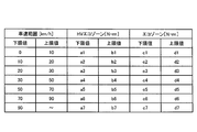
- FIG. 4 is a diagram illustrating an example of the eco zone table.
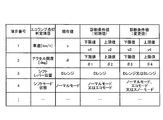
- FIG. 5 is a diagram illustrating an example of the HV eco-zone travel determination condition table.
- FIG. 6 is a diagram illustrating an example of the eco lamp lighting determination condition table.
- FIG. 1 is an explanatory diagram for explaining an outline of a fuel-saving driving diagnosis device, a fuel-saving driving diagnosis system, and a fuel-saving driving diagnosis method.
- FIG. 2 is a diagram illustrating a display mode of the eco lamp and the vehicle power display state quantity display unit.
- FIG. 7 is a diagram illustrating an example of the HV eco-zone out-of-range excess rank weighting coefficient table.
- FIG. 8 is a diagram illustrating an example of a fuel-saving driving advice table that stores fuel-saving driving advice in accordance with the eco lamp lighting driving score and the HV eco-zone driving score.
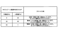
- FIG. 9 is a diagram illustrating an example of a fuel-saving driving advice table that stores fuel-saving driving advice in accordance with the HV eco-zone out-of-range driving score.
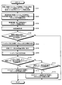
- FIG. 10 is a flowchart showing a fuel-saving driving diagnosis processing procedure.
- FIG. 11 is a flowchart showing an eco lamp lighting determination processing procedure.
- FIG. 12 is a flowchart illustrating a fuel-saving driving diagnosis processing procedure according to an example of a modified embodiment.
- FIG. 13 is a flowchart showing a fuel-saving driving scoring result advice notification processing procedure.
- FIG. 14 is a diagram illustrating an example of a display mode of the eco lamp lighting travel score, the travel score within the HV eco zone range, and the travel score outside the HV eco zone range.
- FIG. 15 is a diagram illustrating an example of a display mode of fuel-saving driving advice.
- FIG. 16 is a diagram illustrating an example of a display mode of fuel-saving driving advice.
- FIG. 17 is a functional block diagram illustrating a configuration of a fuel-saving driving diagnosis device, an HV traveling control device, and related elements according to an example of a modified embodiment.
- a vehicle disclosed in an example of the following embodiment includes both a gasoline engine (or another engine using fossil fuel as energy) and a drive motor (hereinafter abbreviated as a motor), and switches a drive source according to a driving situation.
- a hybrid car hereinafter abbreviated as HV (Hybrid Vehicle)).
- the present invention is not limited to HV, and can be widely applied to any vehicle that travels using a motor as a driving force, such as an electric vehicle or a fuel cell vehicle.
- the vehicle transmission mechanism described below will be described by taking an automatic transmission mechanism or a continuously variable transmission mechanism as an example.
- the disclosed fuel-saving driving diagnosis device, fuel-saving driving diagnosis system, and fuel-saving driving diagnosis method are to compare the driving operation state of the HV driver, particularly the driving operation state of acceleration / deceleration with both the eco-range and the HV eco-range. Based on this, it is determined whether or not the fuel-saving driving is performed.
- the driving operation state of the driver is the accelerator opening accompanying acceleration, and is the same as the required torque required for the drive source.
- the eco range is a range in which torque that can be accelerated without causing an extreme deterioration in fuel consumption is set as an upper limit value.
- the HV eco range is a range having a torque (HV eco information) indicating the limit of travel by the motor as an upper limit value. Both the eco range and the HV eco range are values that change according to the vehicle type and the vehicle speed. The HV eco-range also changes according to motor characteristics, motor temperature, and battery SOC (State of Charge).
- the eco range has a lower limit of 0, but the HV eco range is a range in which a negative value corresponding to the vehicle type is set as the lower limit in order to clearly indicate power generation by the regenerative braking function of the motor.
- the HV eco-range indicates a range in which the motor is efficiently used according to the motor characteristics.
- the required torque relative amount is calculated based on the following equation.
- the required torque relative amount is a percentage of the required torque (current value) with respect to the eco-range required torque (upper limit value) at the current vehicle speed.
- the eco-range required torque (upper limit value) is an upper limit value of the eco-range, and this upper limit value is set to 100 [%].
- the acceleration of the vehicle that does not exceed the HV eco-range required torque (upper limit value) indicates that the motor is being used effectively. Therefore, evaluating the travel within the HV eco-range required torque (upper limit) range on condition that the later-described eco-lamp 16b is lit is used to evaluate the fuel efficiency of driving the vehicle using the motor as a drive source. It has great significance.
- FIG. 2 is a diagram illustrating a display mode of the eco lamp and the vehicle power display state quantity display unit.
- the eco lamp 16b is a lamp that has existed in the past and is lit when an eco operation that satisfies various lighting conditions is performed.
- FIG. 2D shows a state where the eco lamp 16b is turned off. Except FIG.2 (d), the lighting state of the eco lamp 16b is shown.
- the vehicle power display state quantity display unit 16a is an indicator that updates and displays the required torque relative quantity calculated by the above equation (1), for example, every 100 milliseconds.
- the required torque relative amount is referred to as a vehicle power display state display amount.
- the eco zone 501 of the vehicle power display state quantity display unit 16a is a zone determined by the upper limit value and the lower limit value of the eco range.
- the HV eco zone 502 is a zone determined by the upper limit value and the lower limit value of the HV eco range.
- the maximum display state quantity 503 is an upper limit on an indicator that can display the vehicle power display state quantity 505.
- the vehicle power display state quantity non-eco zone 504 is a zone from the portion where the upper limit value of the eco zone 501 is exceeded to the maximum display state quantity 503.
- the upper limit value and the lower limit value of the HV eco zone 502 are variable according to the vehicle type and the vehicle speed.
- the value indicated by the vehicle power display state quantity 505 is also variable according to the vehicle type and the vehicle speed. Note that the vertical axis indicated by “0” in the figure is a boundary line between the positive region and the negative region of the eco zone 501 and the HV eco zone 502.
- the vehicle power display state quantity 505 shown in FIG. 2B indicates that the vehicle is in the HV eco zone 502 and HV eco driving that is cruise / acceleration within the HV eco zone range is being performed.
- the vehicle power display state quantity 505 shown in FIG. 2C is outside the HV eco-zone 502 but inside the eco-zone 501, it indicates that the cruise / acceleration is within the eco-zone range.
- the vehicle power display state quantity 505 shown in FIG. 2D is outside the eco zone 501, it indicates that the acceleration is excessive outside the eco zone range. Further, since the vehicle power display state quantity 505 shown in FIG. 2E is within the negative region of the HV eco-zone 502, it indicates that the vehicle is decelerated within the HV eco-zone range (motor regenerative brake use + accelerator off). ing.
- the vehicle power display state quantity 505 shown in FIG. 2 (f) is outside the negative region of the HV eco zone 502, indicating that the vehicle is decelerating outside the HV eco zone (using a mechanical brake).
- the conditions under which the acceleration / deceleration of the vehicle is diagnosed as ecological acceleration / deceleration within the HV zone range are that the eco lamp 16b is lit and the vehicle power display state quantity 505 is within the HV eco zone 502 range.
- the driver can easily recognize whether the acceleration / deceleration is ecological or not, and be aware that the acceleration / deceleration is ecological. It becomes possible to improve.
- the indicator display makes it possible to ascertain an allowable range of a trade-off between fuel saving and comfortable driving, such as wanting to enjoy comfortable driving (acceleration / deceleration) while maintaining within the fuel saving range.
- FIG. 3 is a functional block diagram illustrating a configuration related to the fuel-saving driving diagnosis device 10a and the HV traveling control device 20a of the vehicle 1a according to an example of the embodiment.
- the fuel-saving driving diagnosis device 10a includes a fuel-saving driving diagnosis unit 11, a fuel-saving driving scoring unit 12, a fuel-saving driving advice generation unit 13, an in-vehicle network interface unit 14, and an output interface unit. 15.
- the fuel-saving driving diagnosis device 10a is connected to the HV traveling control device 20a via the in-vehicle network interface unit 14 and the in-vehicle network 100.
- the HV travel control device 20a is a computer that controls HV travel control, and includes a required torque calculation unit 21a, an HV eco-zone information calculation unit 21b, a motor characteristic information management unit 21c, and a vehicle type information management unit 21d.
- a battery monitoring device 23 that monitors the state of the battery that stores the electric power supplied to the motor that drives the vehicle is connected to the HV traveling control device 20a.
- an engine control device 24a that controls a gasoline engine that drives the vehicle and a motor control device 24b that controls a motor that drives the vehicle are connected to the HV traveling control device 20a.
- a brake control device 25 is connected to the HV traveling control device 20a.
- the brake control device 25 controls the mechanical brake in accordance with the driver's brake operation, and controls the motor to be used as a regenerative brake in accordance with the driver's shift lever operation.
- the HV traveling control device 20a includes a vehicle speed sensor 26 that detects the vehicle speed of the current vehicle, an accelerator operation amount sensor 27 that detects the accelerator operation amount of the current driver, and the shift lever position and shift of the current vehicle.
- a shift sensor 28 that detects the mode state and a vehicle speed pulse signal integrated value storage unit 29 are connected.
- the vehicle speed pulse signal integrated value storage unit 29 stores a vehicle speed pulse signal integrated value that is integrated one by one assuming that the pulse sensor provided on the inner diameter of the wheel of the vehicle 1a detects the vehicle speed pulse signal every rotation of the wheel. . That is, the vehicle speed pulse signal integrated value is a value obtained by integrating the number of wheel rotations. By calculating the difference between the vehicle speed pulse signal integrated values every predetermined time (for example, 100 milliseconds) and multiplying by the outer peripheral length of the wheel, the travel distance of the vehicle 1a at the predetermined time can be calculated.
- the required torque calculation unit 21a of the HV traveling control device 20a calculates a required torque for accelerating the vehicle 1a according to the accelerator operation amount (accelerator opening) by the driver detected by the accelerator operation amount sensor 27.
- the HV eco-zone information calculation unit 21b of the HV travel control device 20a includes motor characteristics acquired from the motor characteristic information management unit 21c, vehicle type information acquired from the vehicle type information management unit 21d, and a motor monitored by the motor control device 24b. Based on the temperature and the SOC of the battery monitored by the battery monitoring device 23, HV eco-zone information corresponding to the vehicle speed is calculated.
- the HV eco zone information is a lower limit value and an upper limit value that define the HV eco range of the required torque for each vehicle speed.
- the HV eco-zone information calculated by the HV eco-zone information calculation unit 21b is delivered to the diagnosis condition management unit 11a of the fuel-saving driving diagnosis device 10a.
- the diagnosis condition management unit 11a stores the HV eco zone information in the HV eco zone column of the eco zone table shown in FIG.
- the value stored in the eco zone column of the eco zone table is calculated and stored by the eco zone information calculation unit 11b as described later.
- the fuel-saving driving diagnosis device 10a is connected to the vehicle power display state quantity display unit 16a, the eco lamp 16b, and the display unit 16c having a display screen via the output interface unit 15.
- the fuel-saving driving diagnosis unit 11 includes a diagnosis condition management unit 11a, an eco zone information calculation unit 11b, a vehicle power display state quantity calculation determination unit 11c, an eco lamp lighting determination unit 11d, and a travel distance integration unit 11e.
- the diagnosis condition management unit 11a manages the condition for determining that the driving is an ecological driving in the HV eco zone, that is, the condition in which the vehicle power display state quantity is in the HV eco zone range and the eco lamp 16b is in the lighting state. Specifically, an eco zone table shown in FIG. 4, an HV eco zone travel determination condition table shown in FIG. 5, and an eco lamp lighting determination condition table shown in FIG. 6 are stored.
- the eco zone table shown in FIG. 4 stores the lower limit value and upper limit value of the HV eco zone for each vehicle speed range calculated by the HV eco zone information calculation unit 21b.
- the eco zone table stores a lower limit value and an upper limit value of the eco zone for each vehicle speed range calculated based on the vehicle type information by the eco zone information calculation unit 11b described later.
- the HV eco-zone travel determination condition table shown in FIG. 5 includes, for example, a vehicle power state display amount [%] as a determination item for determining that the vehicle is traveling within the HV eco-zone range.
- the HV eco zone travel determination condition table stores the current value, diagnosis condition value (initial value), and diagnosis condition value (change value) of each determination item.
- the current value P of the vehicle power display state quantity in the HV eco-zone travel determination condition table is obtained by referring to the eco-zone table for the required torque calculated by the required torque calculation unit 21a of the HV travel control device 20a every 100 milliseconds.
- the current vehicle speed eco-zone upper limit value di i is 1 to 7 depending on the current vehicle speed).
- the diagnosis condition value (initial value) in the HV eco-zone travel determination condition table is the upper limit value of eco-zone information, motor characteristics, vehicle type information, and the remaining battery capacity monitored by the battery monitoring device 23 by the HV eco-zone information calculation unit 21b. Based on the vehicle speed.
- the diagnosis condition value (change value) is determined by the diagnosis condition management unit 11a based on the map information from the map information DB 17a of the car navigation device 17 and the road condition and the traffic condition received by the road information receiving device 18. The value is changed from the value (initial value).
- the diagnosis condition value (change value) is a value that relaxes or tightens the diagnosis condition value (initial value).
- the road information receiving device 18 is a VICS (registered trademark) receiving device or a DSRC (Dedicated Short Range Communications, road-to-vehicle communication) device.
- VICS registered trademark
- DSRC Dedicated Short Range Communications, road-to-vehicle communication
- the eco lamp lighting determination condition table shown in FIG. 6 includes, for example, vehicle speed [k / m], accelerator opening (driver's accelerator operation angle) ⁇ [deg], shift lever position, and shift mode as determination items for lighting the eco lamp 16b. There are states.
- the eco lamp lighting determination condition table stores the current value, diagnosis condition value (initial value), and diagnosis condition value (change value) of each determination item.
- the current value v of the vehicle speed, the current value ⁇ of the accelerator opening, the shift lever position, and the shift mode state in the eco lamp lighting determination condition table are, for example, every 100 milliseconds via the HV traveling control device 20a, the vehicle speed sensor 26, the accelerator. It is a value acquired from the operation amount sensor 27 and the shift sensor 28.
- the shift lever positions include “P” (Parking, parking), “R” (Reverse, reverse), “D” (Drive, normal driving), “N” (Neutral, neutral), “B” (Break , Regenerative braking by a motor), “2” (Second, second gear position), “1” (First, first gear position), and the like. Normally, driving with “D” selected as the shift lever position leads to fuel-saving driving.
- the shift mode state is a function for arranging the travel of the vehicle 1a by complementing the shift lever selection, and the function can be turned on and off with a switch attached to the shift lever.
- the shift mode states include “normal mode” (normal state), “eco mode” (state in which fuel-saving driving is performed), “sport mode” (state in which sporty driving is performed), “snow mode” (in snowy roads) To ensure safe driving). Normally, driving by selecting “normal mode” or “eco mode” as the shift mode state leads to fuel-saving driving.
- the diagnosis condition value (initial value) in the eco lamp lighting determination condition table is a preset value.
- the diagnosis condition value (change value) is determined by the diagnosis condition management unit 11a based on the map information from the map information DB 17a of the car navigation device 17 and the road condition and the traffic condition received by the road information receiving device 18. The value is changed from the value (initial value).
- the diagnosis condition value (change value) is a value that relaxes or tightens the diagnosis condition value (initial value).
- the reason why the diagnostic condition management unit 11a relaxes or tightens the diagnostic condition value according to the map information, the road condition, and the traffic condition is as follows.
- the display and lighting of the vehicle power display state quantity display unit 16a and the eco lamp 16b are information indicating the driver's fuel-saving driving. Then, when determining whether or not the driver's driving is ecological based on the display state and lighting state of the vehicle power display state quantity display unit 16a and the eco lamp 16b, the road environment and traffic on which the vehicle 1a travels are determined. If you judge without considering the situation, it will not be fair.
- the diagnostic condition management unit 11a relaxes or tightens the diagnostic condition values according to map information, road conditions, and traffic conditions, thereby making the diagnosis fairness and scoring fairness. To obtain the consent of the driver as the user.
- the relaxation or strictness of the diagnostic condition values according to the map information and the road conditions and traffic conditions is to shift the lower and upper limits indicated by numerical values by, for example, about 20 to 30%, and the shift lever position And the shift mode state is to add or delete conditions.
- the eco-zone information calculation unit 11b is based on the vehicle type information delivered from the HV travel control unit 20a, and the upper limit value of the torque for each vehicle speed that can perform acceleration without causing an extreme deterioration in fuel consumption even when a gasoline engine is used.
- the eco-zone information including the information is calculated.
- the eco zone information stores a lower limit value and an upper limit value for each vehicle speed in the eco zone column of the eco zone table.
- the vehicle power display state amount calculation determination unit 11c calculates the required torque T at the current vehicle speed v calculated by the required torque calculation unit 21a to the upper limit value of the eco-zone of the corresponding vehicle speed calculated by the eco-zone information calculation unit 11b (see FIG. 4).
- the vehicle power display state quantity is calculated by dividing by. Then, the calculated vehicle power display state quantity is displayed on the vehicle power display state quantity display unit 16a.
- the vehicle power display state quantity is a required torque relative quantity calculated by the above equation (1).
- the vehicle power display state quantity calculation determination unit 11c determines that the calculated vehicle power display state quantity is within the range between the lower limit value and the upper limit value of the diagnostic condition value (change value) of the vehicle power display state quantity shown in FIG. It is determined whether or not there is.
- the vehicle power display state quantity is within the range between the lower limit value and the upper limit value of the diagnosis condition value (change value)
- the vehicle power display state quantity calculation determination unit 11c determines that the calculated vehicle power display state quantity is the diagnosis condition value of the vehicle power display state quantity shown in FIG. Value) is within the range of the lower limit value and the upper limit value.
- the eco lamp lighting determination unit 11d indicates that the current vehicle speed, accelerator opening, shift lever position, and shift mode state (referred to as eco lamp lighting determination items) of the vehicle 1a acquired through the HV traveling control device 20a are shown in FIG. It is determined whether or not each of the indicated diagnostic condition values (change values) is satisfied. This determination is also a fuel-saving driving diagnosis. When all the eco lamp lighting determination items satisfy the diagnostic condition value (changed value), the eco lamp lighting determination unit 11d lights the eco lamp 16b.
- eco lamp lighting determination unit 11d determines that each of the eco lamp lighting determination items is within the range of the lower limit value and the upper limit value of each diagnostic condition value (initial value) shown in FIG. It is determined whether or not there is.
- the mileage accumulating unit 11e calculates a 100 msec mileage acquired every 100 milliseconds from the vehicle speed pulse signal accumulated value storage unit 29 via the HV cruising control device 20a, a one-trip mileage, an eco lamp lighting mileage, an HV eco zone range Add to the inside travel distance and the travel distance outside the HV eco-zone.
- the one-trip travel distance is the distance traveled by the vehicle 1a from ignition on to off.
- the eco lamp lighting travel distance is the distance traveled by the eco lamp 16b being lit in the one trip travel distance.
- the travel distance in the HV eco zone range is a distance of the one trip travel distance in which the eco lamp 16b is lit and the vehicle power display state amount travels within the HV eco zone range.
- the travel distance outside the HV eco-zone is the distance traveled when the vehicle power display state quantity is out of the HV eco-range within the one-trip travel distance.
- the HV eco-zone out-of-range travel distance is determined by a weighting factor by which each travel distance is multiplied according to the excess ratio of the HV eco-zone range.
- the travel distance outside the HV eco-zone is calculated as excess rank A travel distance ⁇ ⁇ 1 + excess rank B travel distance ⁇ ⁇ 2 + excess rank C travel distance ⁇ ⁇ 3.
- the travel distance outside the HV eco-zone is increased and integrated.
- the fuel-saving driving scoring unit 12 of the fuel-saving driving diagnostic device 10a scores the driver's driving based on each integrated value accumulated by the travel distance integrating unit 11e.
- the eco lamp lighting running score is calculated by the following equation.
- the HV eco-zone out-of-range running score is calculated.
- the eco lamp lighting running score and the running score within the HV eco zone range are “good” scores for evaluating that the driver has performed fuel-saving driving.
- the HV eco-zone out-of-range driving score is a “bad” score that measures that the driver has neglected fuel-saving driving.
- the fuel-saving driving scoring unit 12 causes the display unit 16c to display the eco lamp lighting travel score, the travel score within the HV eco zone range, and the travel score outside the HV eco zone range.
- the total score may be calculated by using a “good” score as a scoring material and a “bad” score as a scoring material.
- the fuel-saving driving advice generation unit 13 of the fuel-saving driving diagnosis device 10a displays the fuel-saving driving advice illustrated in FIG. 8 on the display unit 16c according to the eco lamp lighting driving score and the driving score within the HV eco zone range. Further, the fuel-saving driving advice generation unit 13 displays the fuel-saving driving advice illustrated in FIG. 9 on the display unit 16c according to the HV eco-zone out-of-range driving score. 15 and 16 are diagrams illustrating an example of a display mode in which fuel-saving driving advice is displayed on the display unit 16c.
- the fuel-saving driving advice generation unit 13 may generate a message that immediately responds to each score from the template message according to the eco lamp lighting running score, the running score within the HV eco zone range, and the running score outside the HV eco zone range.
- FIG. 10 is a flowchart showing a fuel-saving driving diagnosis processing procedure. This process is a process executed every 100 milliseconds, for example.
- the diagnostic condition management unit 11a obtains vehicle speed, vehicle speed pulse sensor integrated value, accelerator opening, shift lever position and shift mode state, required torque, and HV eco-zone information from the HV travel control device 20a. Obtain (step S101).
- the travel distance integrating unit 11e calculates a 100 msec travel distance from the difference between the previously acquired vehicle speed pulse sensor integrated value and the currently acquired vehicle speed pulse sensor integrated value (step S102). Subsequently, the travel distance integrating unit 11e adds the 100 msec travel distance calculated in step S102 to the one-trip travel distance (step S103).
- the eco zone information calculation unit 11b calculates the eco zone information for each vehicle speed based on the vehicle type information (step S104). Subsequently, the diagnostic condition management unit 11a acquires map information from the map information DB 17a (step S105).
- the diagnosis condition management unit 11a determines whether or not the current position of the vehicle is a point where the diagnosis condition needs to be changed (step S106). When it is determined that the point needs to be changed (Yes in Step S106), the process proceeds to Step S107, and when it is not determined that the point needs to be changed (No in Step S106). ), The process proceeds to step S108.
- step S107 the diagnostic condition management unit 11a changes the diagnostic conditions for fuel-saving driving based on the acquired map information.
- step S108 the vehicle power display state quantity calculation determination unit 11c calculates a vehicle power display state quantity and displays it on the vehicle power display state quantity display unit 16a.
- the eco lamp lighting determination unit 11d executes an eco lamp lighting determination process (step S109). Details of the eco lamp lighting determination process will be described later with reference to FIG.
- the vehicle power display state quantity calculation determination unit 11c determines whether or not the eco lamp 16b is turned on and the vehicle power display state quantity is within the range of the HV eco zone (step S110).
- the process proceeds to step S111, the eco lamp 16b is lit, and the vehicle power display state quantity is When it is not determined that it is within the range of the HV eco-zone (No at Step S110), the process proceeds to Step S112.
- step S111 the travel distance integrating unit 11e adds the travel distance calculated in step S102 to the travel distance within the HV eco-zone range.
- step S112 the vehicle power display state quantity calculation determination unit 11c determines whether or not the vehicle power display state quantity is within the range of the HV eco zone.
- the fuel-saving driving diagnosis process ends.
- the 100 msec travel distance calculated at step S102 is added to the travel distance outside the HV eco zone (step S113).
- the fuel-saving driving diagnosis process ends.
- FIG. 11 is a flowchart showing an eco lamp lighting determination processing procedure. As shown in the figure, first, the eco lamp lighting determining unit 11d initializes the eco lamp lighting flag to on (step S121).
- the eco lamp lighting determining unit 11d determines whether or not the vehicle speed is within the range of the diagnostic condition value (step S122). When it is determined that the vehicle speed is within the range of the diagnostic condition value (Yes at Step S122), the process proceeds to Step S123. When the vehicle speed is not determined to be within the range of the diagnostic condition value (No at Step S122), Control goes to step S126.
- the eco lamp lighting determination unit 11d determines whether or not the accelerator opening is within the range of the diagnostic condition value (step S123). When it is determined that the accelerator opening is within the range of the diagnostic condition value (Yes at Step S123), the process proceeds to Step S124, and when the accelerator opening is not determined to be within the range of the diagnostic condition value (Step S123). (No in S123), the process proceeds to step S126.
- the eco lamp lighting determining unit 11d determines whether or not the shift lever position satisfies the diagnostic condition value (step S124). If it is determined that the shift lever position satisfies the diagnostic condition value (Yes at Step S124), the process proceeds to Step S125. If the shift lever position is not determined to satisfy the diagnostic condition value (No at Step S124), Step S126 is performed. Move on.
- the eco lamp lighting determining unit 11d determines whether or not the shift mode state satisfies the diagnostic condition value (step S125). If it is determined that the shift mode state satisfies the diagnostic condition value (Yes at Step S125), the process proceeds to Step S127. If the shift lever position is not determined to satisfy the diagnostic condition value (No at Step S125), Step S126 is performed. Move on.
- step S126 the eco lamp lighting determining unit 11d turns off the eco lamp lighting flag.
- step S127 the eco lamp lighting determining unit 11d determines whether or not the eco lamp lighting flag is on.
- the eco lamp lighting determining unit 11d lights the eco lamp 16b (step S128), and the eco lamp lighting travel distance is calculated in step S102 of FIG. The 100 msec travel distance is added (step S129).
- step S104 is executed after step S102, and step S103 is executed when the determination in step S106 is affirmative. It is also good to do. After execution of step S103, steps S108 to S113 are executed. If the determination in step S106 is negative, the fuel-saving driving diagnosis process is immediately performed.
- the diagnosis itself is not performed at the point where the current position of the vehicle needs to change the diagnosis condition, and both the one-trip travel distance and the travel distance within the HV eco-zone range are 100 msec. Do not add mileage. Even in this way, it is possible to perform a fair fuel-saving driving diagnosis in consideration of the traveling conditions and traffic conditions of the vehicle 1a.
- FIG. 13 is a flowchart showing a fuel-saving driving scoring result advice notification processing procedure.
- the fuel-saving driving scoring unit 12 determines whether or not the one-trip running is finished (step S201). When it is determined that the one-trip travel is finished (Yes at Step S201), the process proceeds to Step S202, and when it is not determined that the one-trip travel is finished (No at Step S201), Step S201 is repeated.
- step S202 the fuel-saving driving scoring unit 12 calculates the eco lamp lighting score, the HV eco-zone range running score, and the HV eco-zone range running score based on the above equations (2) to (4), respectively.
- the fuel-saving driving scoring unit 12 displays each score calculated by the process of step S202 on the display unit 16c (step S203).
- the fuel-saving driving advice generation unit 13 causes the display unit 16c to display an advice message for promoting awareness of fuel-saving driving corresponding to each of the eco lamp lighting score, the HV eco-zone range running score, and the HV eco-zone range running score. (Step S204).
- the fuel-saving driving scoring result advice notification process ends.
- the fuel-saving driving diagnosis device 10 b and the HV traveling control device 20 b of the vehicle 1 b have the fuel-saving driving diagnosis unit 11 of the fuel-saving driving diagnosis device 10 a of the vehicle 1 a shown in FIG. 3.
- the HV traveling control device 20b may have a fuel-saving driving diagnosis unit 22. In this case, only the configurations of the fuel-saving driving diagnosis device and the HV traveling control device are changed, and the rest is the same as the example of the embodiment. With such a configuration, the configuration of the fuel-saving driving diagnosis device 10b can be simplified and the processing load can be reduced.
- the fuel-saving driving diagnosis unit 22 includes a diagnosis condition management unit 22a, an eco-zone information calculation unit 22b, a vehicle power display state quantity calculation determination unit 22c, an eco-lamp lighting determination unit 22d, and a travel distance integration unit 22e.
- a diagnosis condition management unit 22a an eco-zone information calculation unit 22b
- a vehicle power display state quantity calculation determination unit 22c a vehicle power display state quantity calculation determination unit 22c
- an eco-lamp lighting determination unit 22d a travel distance integration unit 22e.
- the eco lamp lighting determining unit 22d and / or the travel distance integrating unit 22e may be included in the fuel-saving driving diagnosis device 10b instead of the fuel-saving driving diagnosis unit 22.
- diagnosis and scoring of the vehicle power display state quantity may be performed without assuming that the eco lamp 16b is turned on.
- a gravity sensor is employed instead of the map information DB 17a. Can do.
- diagnosis and scoring of the vehicle power display state quantity may be performed by changing the diagnosis condition value of the vehicle power display state quantity in consideration of the weight depending on the number of passengers in the vehicle, the loaded cargo weight, and the like.
- the score may be added and the scoring may be performed. Further, scoring may be performed by changing the weighting of the score in accordance with the usage rate of the charging power related to the required torque generation.
- the notification method for notifying the driver of the vehicle of the scoring result and advice is not limited to the display on the display unit 16c, and may be a notification method using sound or voice.
- the diagnosis conditions for the fuel-saving driving diagnosis are relaxed or tightened in consideration of the driving conditions of the vehicle.
- the accuracy of driving scoring can be increased.
- the fuel-saving driving diagnosis conditions that have been determined in advance are relaxed or stricter based on road conditions, traffic conditions, road surface conditions, weather conditions, etc. It was decided to do.
- the present invention is not limited thereto, and fuel-saving driving diagnosis conditions are generated based on road conditions, traffic conditions, road surface conditions, weather conditions, etc., and fuel-saving driving diagnosis is performed based on the generated fuel-saving driving diagnosis conditions. Also good.
- an appropriate fuel-saving driving diagnosis condition may be selected from the generated fuel-saving driving diagnosis conditions, and fuel-saving driving diagnosis may be performed based on the selected fuel-saving driving diagnosis conditions. This makes it possible to perform a more fair fuel-saving driving diagnosis based on the flexible fuel-saving driving diagnosis conditions according to the situation rather than the fixed fuel-saving driving diagnosis conditions.
- all or part of the processes described as being automatically performed can be manually performed, or the processes described as being manually performed can be performed. All or a part can be automatically performed by a known method.
- the processing procedure, control procedure, specific name, and information including various data and parameters shown in the example of the above embodiment can be arbitrarily changed unless otherwise specified.
- each component of each illustrated apparatus is functionally conceptual and does not necessarily need to be physically configured as illustrated.
- the specific form of distribution or integration of each device is not limited to that shown in the figure, and all or a part thereof may be functionally or physically distributed or arbitrarily distributed in arbitrary units according to various loads or usage conditions. Can be integrated and configured.
- each processing function performed by each device is a CPU (Central Processing Unit) (or a microcomputer such as an MPU (Micro Processing Unit) or MCU (Micro Controller Unit)) and It may be realized by a program that is analyzed and executed by a CPU (or a microcomputer such as an MPU or MCU), or may be realized as hardware by wired logic.
- CPU Central Processing Unit
- MPU Micro Processing Unit
- MCU Micro Controller Unit
- the disclosed fuel-saving driving diagnosis device, fuel-saving driving diagnosis system, and fuel-saving driving diagnosis method diagnose how ecologically the driving of a vehicle driver is, scoring based on the diagnosis result, scoring result and This is useful for improving the driver's awareness of fuel-saving driving, particularly when he / she wants to raise his / her consciousness so that acceleration / deceleration becomes fuel-saving driving by feeding the driver fuel-saving driving advice based on the scoring results.
- Fuel saving driving diagnosis device 11 Fuel saving driving diagnosis unit 11a Diagnosis condition management unit 11b Eco zone information calculation unit 11c Vehicle power display state quantity calculation determination unit 11d Eco lamp lighting determination unit 11e Travel distance integration unit 12 Fuel consumption saving Driving scoring unit 13 Fuel-saving driving advice generating unit 14 In-vehicle network interface unit 15 Output interface unit 16a Vehicle power display state quantity display unit 16b Eco lamp 16c Display unit 17 Car navigation device 17a Map information DB 18 Road information receiving device 20a, 20b HV travel control device 21a Required torque calculation unit 21b HV eco zone information calculation unit 21c Motor characteristic information management unit 21d Vehicle type information management unit 22 Fuel-saving driving diagnosis unit 22a Diagnosis condition management unit 22b Eco zone information calculation unit 22c Vehicle power display state quantity calculation determination unit 22d Eco lamp lighting determination unit 22e Travel distance integration unit 23 Battery monitoring device 24a Engine control device 24b Motor control device 25 Brake control device 26 Vehicle speed sensor 27 Accelerator operation amount sensor 28 Shift sensor 29 Vehicle speed pulse signal Integrated value storage unit
Landscapes
- Engineering & Computer Science (AREA)
- Mechanical Engineering (AREA)
- Transportation (AREA)
- Chemical & Material Sciences (AREA)
- Combustion & Propulsion (AREA)
- Automation & Control Theory (AREA)
- Power Engineering (AREA)
- Life Sciences & Earth Sciences (AREA)
- Sustainable Development (AREA)
- Sustainable Energy (AREA)
- Human Computer Interaction (AREA)
- Electric Propulsion And Braking For Vehicles (AREA)
- Control Of Vehicle Engines Or Engines For Specific Uses (AREA)
- Hybrid Electric Vehicles (AREA)
- Combined Controls Of Internal Combustion Engines (AREA)
Abstract
A vehicle power indication status quantity display unit (16a) displays on an indicator the vehicle power indication status display quantity, which is the required torque for driving a hybrid vehicle divided by the maximum torque which does not excessively worsen the fuel consumption. An HV Eco Zone (502) of the vehicle power indication status quantity display unit (16a) is the zone determined by the upper limit value and the lower limit value of the HV Eco range which indicates that the motor is being effectively utilized as the vehicle travels. It is determined whether or not the vehicle power indication status quantity (505) is within the HV Eco Zone (502). When this quantity is within the HV Eco Zone (502), the diagnosis is that low fuel consumption driving is taking place in relation to acceleration and deceleration. For example, the percentage of the travel distance which was traveled with the vehicle power indication status quantity (505) within the HV Eco Zone (502) range during one trip is made into a score. The driver can be made more aware of low fuel consumption driving in relation to acceleration and deceleration by the provision of appropriate advice to the driver in accordance with the score.
Description
本発明は、電気をエネルギーとして車両を駆動する電気駆動装置を有する車両における運転者の省燃費運転を診断して採点し、採点結果を運転者に対して通知することによって省燃費運転の意識を向上させる省燃費運転診断装置、省燃費運転診断システム、電気駆動装置の制御装置、省燃費運転採点装置及び省燃費運転診断方法に関する。
The present invention diagnoses and scores a driver's fuel-saving driving in a vehicle having an electric drive device that drives the vehicle using electricity as energy, and notifies the driver of the scoring result to raise awareness of fuel-saving driving. The present invention relates to a fuel-saving driving diagnostic device, a fuel-saving driving diagnostic system, an electric drive control device, a fuel-saving driving scoring device, and a fuel-saving driving diagnostic method.
近年、地球環境問題がクローズアップされる中、自動車の省燃費性が改めて重要視されるようになってきている。地球環境問題では、特に、地球温暖化対策が急務となっている。このため、二酸化炭素等の温暖化ガスを排出する従来のガソリンエンジン車等では、改良によっていくら燃費効率を向上させたとしても限界があり、急速な地球温暖化の進行に歯止めを掛ける有効な解決策とはなり得ない。
In recent years, as global environmental issues have been highlighted, the fuel efficiency of automobiles has become increasingly important. In global environmental problems, in particular, countermeasures against global warming are urgently needed. For this reason, conventional gasoline engine vehicles that emit carbon dioxide and other warming gases have limitations, no matter how much the fuel efficiency can be improved by improving them. This is an effective solution to stop the rapid progress of global warming. It cannot be a solution.
そこで、ガソリンエンジンとモータとを搭載し、例えば、低中速走行時には電力をエネルギーとするモータを駆動力とし、高速走行時には化石燃料をエネルギーとするガソリンエンジンを駆動力とするハイブリッドカーが開発されている。
Therefore, a hybrid car equipped with a gasoline engine and a motor, for example, a motor that uses electric power as energy when driving at low and medium speeds, and a gasoline engine that uses fossil fuel as energy when driving at high speeds has been developed. ing.
ハイブリッドカーは、モータを駆動力として走行する場合には、排気ガスを一切排出しないことから、温暖化ガスの排出がなく、地球温暖化の進行の抑制に効果がある。また、モータは、電気をエネルギーとすることから、ガソリンエンジンに比べエネルギー利用効率が高く、省燃費の効果も高い。省燃費の効果は、同じエネルギー量で走行できる距離、若しくは、同じ距離を走行するために消費するエネルギー量という指標で量ることができる。
The hybrid car does not emit any exhaust gas when running with a motor as a driving force, so it does not emit warming gas and is effective in suppressing the progress of global warming. In addition, since the motor uses electricity as energy, it has higher energy utilization efficiency than a gasoline engine and has a high fuel efficiency effect. The fuel saving effect can be measured by an index of a distance that can be traveled with the same energy amount or an energy amount that is consumed to travel the same distance.
しかし、いくら自動車の省燃費性能が高くても、運転者の運転が省燃費に反するものであれば、自動車の高省燃費性能も意味をなさない。そこで、運転車の運転操作が少しでもより省燃費となる様に運転者に報知を行う従来技術が種々考案されてきた。
However, no matter how high the fuel economy performance of a car is, if the driver's driving is contrary to fuel efficiency, the high fuel efficiency performance of a car will not make sense. Accordingly, various conventional techniques have been devised for informing the driver so that the driving operation of the driving vehicle is even more fuel efficient.
例えば、ある従来技術では、現在地点において消費する燃料による単位量換算の走行距離が判定値より大きいと判定される場合に、自動車の走行がエコ的走行(地球環境に配慮した省燃費走行、“エコ”は、“エコロジー”の省略形、以下同様)であるとし、エコ的走行であると判定された場合において走行距離から判定値を減算することによってエコ的走行をエコ数値として数値化したエコ数値を積算することによって、運転者にエコ的走行をどれだけ行ったか否かを報知する車両用表示装置が提案されていた。
For example, in a certain prior art, when it is determined that the unit distance conversion distance based on the fuel consumed at the current location is larger than the determination value, the vehicle travels ecologically (fuel-saving travel in consideration of the global environment, “ “Eco” is an abbreviation of “Ecology”, and the same applies to the following). When it is determined that the vehicle is eco-friendly, the eco-friendly value is calculated by subtracting the judgment value from the travel distance. There has been proposed a vehicle display device that notifies the driver of how much eco-friendly driving has been performed by accumulating numerical values.
また、他の従来技術では、ハイブリッド車の走行試験で運転パターン毎の理想的燃費データを測定しておき、ハイブリッド車の実用走行の運転パターン毎の実燃費データを測定し、理想的燃費データと実燃費データとの差分に基づき実用走行を評価し、実用走行の運転操作に関する情報を運転者に報知するハイブリッド車用運転操作評価装置が提案されていた。
In another conventional technique, ideal fuel consumption data for each driving pattern is measured in a driving test of a hybrid vehicle, and actual fuel consumption data for each driving pattern of practical driving of a hybrid vehicle is measured. There has been proposed a hybrid vehicle driving operation evaluation device that evaluates practical driving based on a difference from actual fuel consumption data and informs a driver of information related to driving operation of practical driving.
また、他の従来技術では、ハイブリッド電気自動車の走行距離と燃料消費量とに基づいて算出された瞬間燃費をハイブリッド電気自動車の加速度をパラメータとして補正することによって算出された補正値をエコメータに表示することによって、ハイブリッド電気自動車の走行効率を運転者に報知する表示装置と表示装置が表示する走行効率の算出方法が提案されていた。
In another conventional technique, the correction value calculated by correcting the instantaneous fuel consumption calculated based on the travel distance and fuel consumption of the hybrid electric vehicle using the acceleration of the hybrid electric vehicle as a parameter is displayed on the ecometer. Thus, a display device that notifies the driver of the traveling efficiency of the hybrid electric vehicle and a method of calculating the traveling efficiency displayed by the display device have been proposed.
また、他の従来技術では、自動車の走行距離と燃料消費量とから燃費に関する情報を算出して表示し、燃費に関する情報に応じてランプの輝度及び色彩を変化させることによって、運転者に燃費に関する情報を瞬時に視認させることができる燃費表示装置が提案されていた。
In another prior art, information related to fuel consumption is calculated and displayed from the mileage of the vehicle and fuel consumption, and the brightness and color of the lamp are changed in accordance with the information related to fuel consumption. There has been proposed a fuel consumption display device capable of instantly viewing information.
しかしながら、上記従来技術では、次の様な問題点があった。すなわち、単に、走行距離を消費燃料量で割った平均燃費や、例えば0.1秒ごとの瞬間燃費などの燃費に関する情報を算出して報知するだけでは、運転者はその燃費に関する情報の絶対的かつ公平な良否判断を行うことができなかった。これは、自動車の走行条件が状況に応じて多様であり、走行条件が燃費に与える影響が大きいためである。
However, the above prior art has the following problems. That is, simply by calculating and reporting information on fuel consumption such as the average fuel consumption obtained by dividing the mileage by the amount of fuel consumed, or instantaneous fuel consumption, for example, every 0.1 second, the driver can obtain absolute information on the fuel consumption. And I was unable to make a fair judgment. This is because the driving conditions of automobiles vary depending on the situation, and the driving conditions have a great influence on fuel consumption.
また、燃費に関する情報が閾値を超えたか否かを判定することによって現在の運転状況の良否を判断することができるが、現在の運転状況の良否の程度が不明である。このため、例えば省燃費の範囲内を維持しつつも気持ち良い走行を楽しみたいといった、省燃費と気持ち良い走行とのトレードオフの許容範囲を見極めるということができなかった。
In addition, it is possible to determine whether the current driving situation is good or not by determining whether or not the fuel consumption information exceeds the threshold value, but the degree of the current driving situation is not clear. For this reason, for example, it has not been possible to determine the allowable range of the trade-off between fuel saving and comfortable driving, such as wanting to enjoy comfortable driving while maintaining within the fuel saving range.
以上の問題点から、燃費向上のためには、運転者の運転操作の改善や省燃費運転の意識向上が必要であるにもかかわらず、従来技術では、公平な基準に基づいた運転者の運転操作評価が行えなかったため、運転者の運転操作の改善意欲や省燃費運転の意識を向上させることができなかった。
Because of the above problems, in order to improve fuel efficiency, it is necessary to improve the driver's driving operation and raise awareness of fuel-saving driving. Because the operation evaluation could not be performed, the driver's willingness to improve driving operation and the awareness of fuel-saving driving could not be improved.
以下に開示する省燃費運転診断装置、省燃費運転診断システム、電気駆動装置の制御装置、省燃費運転採点装置及び省燃費運転診断方法は、上記問題点(課題)を解消するためになされたものであって、燃費に関する情報の絶対的かつ公平な良否判断を行うことを可能とし、省燃費と気持ち良い走行とのトレードオフの許容範囲を示し、運転者の運転操作の改善意欲や省燃費運転の意識を向上させることを可能とすることを目的とする。
The fuel-saving driving diagnosis device, the fuel-saving driving diagnosis system, the control device for the electric drive device, the fuel-saving driving scoring device, and the fuel-saving driving diagnostic method disclosed below are made to solve the above problems (problems). Therefore, it is possible to make an absolute and fair judgment on fuel efficiency information, show the allowable range of trade-off between fuel efficiency and comfortable driving, and the driver's willingness to improve driving operation and fuel efficiency driving It aims to make it possible to improve awareness.
上述した問題を解決し、目的を達成するため、以下に開示する省燃費運転診断装置、省燃費運転診断システム及び省燃費運転診断方法は、電気駆動装置の車両走行に関する制御値で求められる省燃費運転条件を、電気駆動装置の性能特性と前記車両の車速とに基づいて算出し、電気駆動装置の車両走行に関する制御値を取得し、制御値取得部により取得された制御値が、省燃費運転条件算出部により算出された省燃費条件を充足するか否かを判定し、取得された道路状況又は交通状況に応じて、電気駆動装置の車両走行に関する制御値が燃費運転条件を充足するか否かを判定し、電気駆動装置の車両走行に関する制御値が省燃費運転条件を充足するか否かを判定する対象である車両の判定対象走行距離と、該判定対象走行距離のうち省燃費運転条件を充足すると判定された走行距離とに基づいて省燃費運転を採点し、採点結果に基づいて省燃費運転アドバイスを生成し、採点結果及び省燃費運転アドバイスを運転者に通知することを一要件とする。
In order to solve the above-described problems and achieve the object, a fuel-saving driving diagnosis device, a fuel-saving driving diagnostic system, and a fuel-saving driving diagnostic method disclosed below are fuel-saving required by control values related to vehicle travel of an electric drive device. The driving condition is calculated based on the performance characteristics of the electric drive device and the vehicle speed of the vehicle, the control value related to the vehicle running of the electric drive device is acquired, and the control value acquired by the control value acquisition unit is the fuel-saving driving It is determined whether or not the fuel saving condition calculated by the condition calculation unit is satisfied, and whether or not the control value relating to the vehicle driving of the electric drive device satisfies the fuel consumption driving condition according to the acquired road condition or traffic condition. And a determination target travel distance of the vehicle that is a target for determining whether or not the control value related to the vehicle travel of the electric drive device satisfies the fuel efficiency driving condition, and the fuel efficiency saving of the determination target travel distance It is important to score fuel-saving driving based on the mileage determined to satisfy the rolling condition, generate fuel-saving driving advice based on the scoring result, and notify the driver of the scoring result and fuel-saving driving advice. As a requirement.
本発明によれば、燃費に関する情報、特に加減速に関する情報の絶対的かつ公平な良否判断を行うことを可能とし、省燃費と気持ち良い走行とのトレードオフの許容範囲を示して、運転者の運転操作の改善意欲や省燃費運転の意識を向上させることを可能とするという効果を奏する。
According to the present invention, it is possible to make an absolute and fair judgment on the information on fuel consumption, in particular information on acceleration / deceleration, showing the allowable range of the trade-off between fuel saving and comfortable driving, and driving the driver There is an effect that it is possible to improve the willingness to improve the operation and the awareness of fuel-saving driving.
以下に添付図面を参照し、省燃費運転診断装置、省燃費運転診断システム及び省燃費運転診断方法に係る実施形態の一例を詳細に説明する。以下の実施形態の一例で開示する車両は、ガソリンエンジン(若しくは、化石燃料をエネルギーとするその他のエンジン)及び駆動モータ(以下、モータと略記)を双方備え、運転状況に応じて駆動源を切り替えて走行するハイブリッドカー(以下、HV(Hybrid Vehicle)と略記する)である。
Hereinafter, an example of an embodiment related to a fuel-saving driving diagnosis device, a fuel-saving driving diagnosis system, and a fuel-saving driving diagnosis method will be described in detail with reference to the accompanying drawings. A vehicle disclosed in an example of the following embodiment includes both a gasoline engine (or another engine using fossil fuel as energy) and a drive motor (hereinafter abbreviated as a motor), and switches a drive source according to a driving situation. A hybrid car (hereinafter abbreviated as HV (Hybrid Vehicle)).
しかし、HVに限定されず、電気自動車や燃料電池車等、モータを駆動力として走行する車両であれば、広く一般に適用可能である。以下に示す車両の変速機構は、オートマチック変速機構若しくは無段変速機構を例として説明する。
However, the present invention is not limited to HV, and can be widely applied to any vehicle that travels using a motor as a driving force, such as an electric vehicle or a fuel cell vehicle. The vehicle transmission mechanism described below will be described by taking an automatic transmission mechanism or a continuously variable transmission mechanism as an example.
先ず、省燃費運転診断装置、省燃費運転診断システム及び省燃費運転診断方法の概要を説明する。開示の省燃費運転診断装置、省燃費運転診断システム及び省燃費運転診断方法は、HVの運転者の運転操作状態、特に加減速の運転操作状態をエコ範囲及びHVエコ範囲の双方と比較することによって、省燃費運転であるか否かを判定する。
First, an outline of a fuel-saving driving diagnosis device, a fuel-saving driving diagnosis system, and a fuel-saving driving diagnosis method will be described. The disclosed fuel-saving driving diagnosis device, fuel-saving driving diagnosis system, and fuel-saving driving diagnosis method are to compare the driving operation state of the HV driver, particularly the driving operation state of acceleration / deceleration with both the eco-range and the HV eco-range. Based on this, it is determined whether or not the fuel-saving driving is performed.
ここで、運転者の運転操作状態は、加速に伴うアクセル開度であり、駆動源に対して要求する要求トルクと同一である。また、エコ範囲は、極度な燃費悪化を招かない加速を行いうるトルクを上限値とする範囲である。また、HVエコ範囲は、モータでの走行の限界を示すトルク(HVエコ情報)を上限値とする範囲である。エコ範囲及びHVエコ範囲は、いずれも車種及び車速に応じて変化する値である。なお、HVエコ範囲は、さらにモータ特性、モータ温度及び電池のSOC(State of Charge、充電状態)にも応じて変化する。
Here, the driving operation state of the driver is the accelerator opening accompanying acceleration, and is the same as the required torque required for the drive source. In addition, the eco range is a range in which torque that can be accelerated without causing an extreme deterioration in fuel consumption is set as an upper limit value. Further, the HV eco range is a range having a torque (HV eco information) indicating the limit of travel by the motor as an upper limit value. Both the eco range and the HV eco range are values that change according to the vehicle type and the vehicle speed. The HV eco-range also changes according to motor characteristics, motor temperature, and battery SOC (State of Charge).
なお、エコ範囲は0を下限とするが、HVエコ範囲は、モータの回生ブレーキ機能による発電を明示するために、車種に応じた負値を下限とする範囲である。すなわち、HVエコ範囲は、モータ特性に応じて、モータを効率よく使用して走行しているとされる範囲を示すものである。
Note that the eco range has a lower limit of 0, but the HV eco range is a range in which a negative value corresponding to the vehicle type is set as the lower limit in order to clearly indicate power generation by the regenerative braking function of the motor. In other words, the HV eco-range indicates a range in which the motor is efficiently used according to the motor characteristics.
図1を参照すると、運転者の運転操作に応じて要求トルク、HVエコゾーン情報、車速及びその他運転操作に基づいて、車速に応じたエコ範囲要求トルク(上限値)及びHVエコ範囲要求トルク(上限値)の曲線がマッピングされる。
Referring to FIG. 1, the eco-range required torque (upper limit value) and the HV eco-range required torque (upper limit) according to the vehicle speed based on the required torque, HV eco-zone information, vehicle speed, and other driving operations according to the driving operation of the driver. Value) curve is mapped.
ここで、次式に基づき、要求トルク相対量が算出される。
Here, the required torque relative amount is calculated based on the following equation.

すなわち、要求トルク相対量は、現在の車速におけるエコ範囲要求トルク(上限値)に対する要求トルク(現在値)の百分率である。ここで、エコ範囲要求トルク(上限値)は、エコ範囲の上限値であり、この上限値を100[%]とおく。
That is, the required torque relative amount is a percentage of the required torque (current value) with respect to the eco-range required torque (upper limit value) at the current vehicle speed. Here, the eco-range required torque (upper limit value) is an upper limit value of the eco-range, and this upper limit value is set to 100 [%].
また、HVエコ範囲要求トルク(上限値)は、HVエコ範囲の上限値であり、エコ範囲要求トルク(上限値)を100[%]とした場合の百分率をe[%]とおく。要求トルク相対量がエコ範囲要求トルク(上限値)(=100[%])以下であれば、運転者の現在の運転操作はエコであると判定される。さらに、要求トルク相対量がHVエコ範囲要求トルク(上限値)(=e[%])以下であれば、運転者の現在の運転操作は、モータを有効利用してよりエコ的であると判定される。この判定結果は、例えば表示部に表示されることにより運転者に通知され、運転者の省燃費運転の向上に役立てられる。
Also, the HV eco-range required torque (upper limit value) is the upper limit value of the HV eco-range, and the percentage when the eco-range required torque (upper limit value) is 100 [%] is set as e [%]. If the required torque relative amount is equal to or less than the eco-range required torque (upper limit value) (= 100 [%]), it is determined that the driver's current driving operation is eco. Furthermore, if the required torque relative amount is equal to or less than the HV eco-range required torque (upper limit value) (= e [%]), it is determined that the current driving operation of the driver is more ecological by effectively using the motor. Is done. This determination result is notified to the driver, for example, by being displayed on the display unit, and is used to improve the driver's fuel-saving driving.
なお、車種やモータ特性、車速や車両の走行条件等によって違いはあるが、HVエコ範囲要求トルク(上限値)(=e[%])は、エコ範囲要求トルク(上限値)の50%程度の数値である。ここで、HVエコ範囲要求トルク(上限値)を超えない車両の加速は、モータを有効利用して加速していることを示す。よって、後述のエコランプ16bの点灯を条件として、HVエコ範囲要求トルク(上限値)範囲内での走行を評価することは、モータを駆動源として利用する車両の運転の省燃費性を評価する上で大きな意義を有する。
The HV eco-range required torque (upper limit value) (= e [%]) is about 50% of the eco-range required torque (upper limit value), although there are differences depending on the vehicle type, motor characteristics, vehicle speed, vehicle running conditions, etc. It is a numerical value. Here, the acceleration of the vehicle that does not exceed the HV eco-range required torque (upper limit value) indicates that the motor is being used effectively. Therefore, evaluating the travel within the HV eco-range required torque (upper limit) range on condition that the later-described eco-lamp 16b is lit is used to evaluate the fuel efficiency of driving the vehicle using the motor as a drive source. It has great significance.
次に、運転者の現在の運転操作の判定結果を通知する方法の一例として、エコランプ及び車両パワー表示状態量表示部の表示態様について説明する。図2は、エコランプ及び車両パワー表示状態量表示部の表示態様を示す図である。
Next, the display mode of the eco lamp and the vehicle power display state quantity display unit will be described as an example of a method of notifying the determination result of the current driving operation of the driver. FIG. 2 is a diagram illustrating a display mode of the eco lamp and the vehicle power display state quantity display unit.
エコランプ16bは、従来から存在し、種々の点灯条件を充足するエコ的運転が行なわれている時に点灯するランプである。図2(d)は、エコランプ16bの消灯状態を示す。図2(d)以外は、エコランプ16bの点灯状態を示す。
The eco lamp 16b is a lamp that has existed in the past and is lit when an eco operation that satisfies various lighting conditions is performed. FIG. 2D shows a state where the eco lamp 16b is turned off. Except FIG.2 (d), the lighting state of the eco lamp 16b is shown.
一方、車両パワー表示状態量表示部16aは、上記(1)式で算出された要求トルク相対量を、例えば100ミリ秒毎に更新表示するインジケータである。以下では、要求トルク相対量を車両パワー表示状態表示量と呼ぶ。
On the other hand, the vehicle power display state quantity display unit 16a is an indicator that updates and displays the required torque relative quantity calculated by the above equation (1), for example, every 100 milliseconds. Hereinafter, the required torque relative amount is referred to as a vehicle power display state display amount.
車両パワー表示状態量表示部16aのエコゾーン501は、エコ範囲の上限値及び下限値で定まるゾーンである。HVエコゾーン502は、HVエコ範囲の上限値及び下限値で定まるゾーンである。最大表示状態量503は、車両パワー表示状態量505を表示可能なインジケータ上の上限である。
The eco zone 501 of the vehicle power display state quantity display unit 16a is a zone determined by the upper limit value and the lower limit value of the eco range. The HV eco zone 502 is a zone determined by the upper limit value and the lower limit value of the HV eco range. The maximum display state quantity 503 is an upper limit on an indicator that can display the vehicle power display state quantity 505.
車両パワー表示状態量非エコゾーン504は、エコゾーン501の上限値の超過部分から最大表示状態量503までのゾーンである。図2(a)に示すように、HVエコゾーン502の上限値及び下限値は、車種及び車速に応じて可変である。また、同様に、車両パワー表示状態量505が指し示す値も車種及び車速に応じて可変である。なお、図中で“0”で指し示されている縦軸は、エコゾーン501及びHVエコゾーン502の正領域と負領域との境界線である。
The vehicle power display state quantity non-eco zone 504 is a zone from the portion where the upper limit value of the eco zone 501 is exceeded to the maximum display state quantity 503. As shown in FIG. 2A, the upper limit value and the lower limit value of the HV eco zone 502 are variable according to the vehicle type and the vehicle speed. Similarly, the value indicated by the vehicle power display state quantity 505 is also variable according to the vehicle type and the vehicle speed. Note that the vertical axis indicated by “0” in the figure is a boundary line between the positive region and the negative region of the eco zone 501 and the HV eco zone 502.
例えば図2(b)に示す車両パワー表示状態量505は、HVエコゾーン502内にあり、HVエコゾーン範囲内巡航・加速であるHVエコ運転が行われていることを示している。また、図2(c)に示す車両パワー表示状態量505は、HVエコゾーン502外にあるものの、エコゾーン501内にあることから、エコゾーン範囲内巡航・加速であることを示している。
For example, the vehicle power display state quantity 505 shown in FIG. 2B indicates that the vehicle is in the HV eco zone 502 and HV eco driving that is cruise / acceleration within the HV eco zone range is being performed. Moreover, although the vehicle power display state quantity 505 shown in FIG. 2C is outside the HV eco-zone 502 but inside the eco-zone 501, it indicates that the cruise / acceleration is within the eco-zone range.
また、図2(d)に示す車両パワー表示状態量505は、エコゾーン501外にあることから、エコゾーン範囲外の過度な加速であることを示している。また、図2(e)に示す車両パワー表示状態量505は、HVエコゾーン502の負領域内にあることから、HVエコゾーン範囲内減速(モータの回生ブレーキ使用+アクセルオフ時)であることを示している。
Further, since the vehicle power display state quantity 505 shown in FIG. 2D is outside the eco zone 501, it indicates that the acceleration is excessive outside the eco zone range. Further, since the vehicle power display state quantity 505 shown in FIG. 2E is within the negative region of the HV eco-zone 502, it indicates that the vehicle is decelerated within the HV eco-zone range (motor regenerative brake use + accelerator off). ing.
また、図2(f)に示す車両パワー表示状態量505は、HVエコゾーン502の負領域外にあることから、HVエコゾーン範囲外減速(メカブレーキ使用)であることを示している。
Also, the vehicle power display state quantity 505 shown in FIG. 2 (f) is outside the negative region of the HV eco zone 502, indicating that the vehicle is decelerating outside the HV eco zone (using a mechanical brake).
以上をまとめると、車両の加減速がHVゾーン範囲内のエコ的加減速と診断される条件は、エコランプ16bが点灯かつ車両パワー表示状態量505がHVエコゾーン502の範囲にあることである。
In summary, the conditions under which the acceleration / deceleration of the vehicle is diagnosed as ecological acceleration / deceleration within the HV zone range are that the eco lamp 16b is lit and the vehicle power display state quantity 505 is within the HV eco zone 502 range.
このように、車両の加減速に伴う車両パワー表示状態量505をインジケータ表示することによって、運転者に加減速がエコ的か否かを容易に認識させ、加減速がエコ的となるよう意識を向上させることが可能になる。また、インジケータ表示によって、省燃費の範囲内を維持しつつも気持ち良い走行(加減速)を楽しみたいといった、省燃費と気持ち良い走行とのトレードオフの許容範囲を見極めることができる。
Thus, by displaying the vehicle power display state quantity 505 accompanying acceleration / deceleration of the vehicle with an indicator, the driver can easily recognize whether the acceleration / deceleration is ecological or not, and be aware that the acceleration / deceleration is ecological. It becomes possible to improve. Further, the indicator display makes it possible to ascertain an allowable range of a trade-off between fuel saving and comfortable driving, such as wanting to enjoy comfortable driving (acceleration / deceleration) while maintaining within the fuel saving range.
[実施形態の一例]
図3~図16を参照して、省燃費運転診断装置、省燃費運転診断システム及び省燃費運転診断方法に係る実施形態の一例を説明する。図3は、実施形態の一例に係る車両1aの省燃費運転診断装置10a及びHV走行制御装置20aに関連する構成を示す機能ブロック図である。 [Example of embodiment]
With reference to FIGS. 3 to 16, an example of an embodiment related to a fuel-saving driving diagnosis device, a fuel-saving driving diagnosis system, and a fuel-saving driving diagnosis method will be described. FIG. 3 is a functional block diagram illustrating a configuration related to the fuel-savingdriving diagnosis device 10a and the HV traveling control device 20a of the vehicle 1a according to an example of the embodiment.
図3~図16を参照して、省燃費運転診断装置、省燃費運転診断システム及び省燃費運転診断方法に係る実施形態の一例を説明する。図3は、実施形態の一例に係る車両1aの省燃費運転診断装置10a及びHV走行制御装置20aに関連する構成を示す機能ブロック図である。 [Example of embodiment]
With reference to FIGS. 3 to 16, an example of an embodiment related to a fuel-saving driving diagnosis device, a fuel-saving driving diagnosis system, and a fuel-saving driving diagnosis method will be described. FIG. 3 is a functional block diagram illustrating a configuration related to the fuel-saving
図3に示すように、省燃費運転診断装置10aは、省燃費運転診断部11と、省燃費運転採点部12と、省燃費運転アドバイス生成部13と、車載ネットワークインターフェース部14と、出力インターフェース部15とを有する。また、省燃費運転診断装置10aは、車載ネットワークインターフェース部14及び車載ネットワーク100を介してHV走行制御装置20aと接続されている。HV走行制御装置20aは、HVの走行制御をつかさどるコンピュータであり、要求トルク算出部21aと、HVエコゾーン情報算出部21bと、モータ特性情報管理部21cと、車種情報管理部21dとを有する。
As shown in FIG. 3, the fuel-saving driving diagnosis device 10a includes a fuel-saving driving diagnosis unit 11, a fuel-saving driving scoring unit 12, a fuel-saving driving advice generation unit 13, an in-vehicle network interface unit 14, and an output interface unit. 15. The fuel-saving driving diagnosis device 10a is connected to the HV traveling control device 20a via the in-vehicle network interface unit 14 and the in-vehicle network 100. The HV travel control device 20a is a computer that controls HV travel control, and includes a required torque calculation unit 21a, an HV eco-zone information calculation unit 21b, a motor characteristic information management unit 21c, and a vehicle type information management unit 21d.
また、HV走行制御装置20aには、車両を駆動するモータに供給する電力を蓄電する電池の状態を監視する電池監視装置23が接続されている。また、HV走行制御装置20aには、車両を駆動するガソリンエンジンを制御するエンジン制御装置24aと、車両を駆動するモータを制御するモータ制御装置24bとが接続されている。
Also, a battery monitoring device 23 that monitors the state of the battery that stores the electric power supplied to the motor that drives the vehicle is connected to the HV traveling control device 20a. In addition, an engine control device 24a that controls a gasoline engine that drives the vehicle and a motor control device 24b that controls a motor that drives the vehicle are connected to the HV traveling control device 20a.
また、HV走行制御装置20aには、ブレーキ制御装置25が接続されている。ブレーキ制御装置25は、運転者のブレーキ操作に応じてメカニカルブレーキを制御するとともに、運転者のシフトレバー操作に応じてモータを回生ブレーキとして使用する様に制御する。
Further, a brake control device 25 is connected to the HV traveling control device 20a. The brake control device 25 controls the mechanical brake in accordance with the driver's brake operation, and controls the motor to be used as a regenerative brake in accordance with the driver's shift lever operation.
また、HV走行制御装置20aには、現在の車両の車速を検知する車速センサ26と、現在の運転者のアクセル操作量を検知するアクセル操作量センサ27と、現在の車両のシフトレバー位置及びシフトモード状態を検知するシフトセンサ28と、車速パルス信号積算値格納部29とが接続されている。
Further, the HV traveling control device 20a includes a vehicle speed sensor 26 that detects the vehicle speed of the current vehicle, an accelerator operation amount sensor 27 that detects the accelerator operation amount of the current driver, and the shift lever position and shift of the current vehicle. A shift sensor 28 that detects the mode state and a vehicle speed pulse signal integrated value storage unit 29 are connected.
なお、車速パルス信号積算値格納部29は、車両1aの車輪の内径に備えられたパルスセンサが車輪の1回転毎に車速パルス信号を検知したとして1ずつ積算した車速パルス信号積算値を格納する。すなわち、車速パルス信号積算値は、車輪の回転回数を積算した値である。所定時間(例えば100ミリ秒)毎の車速パルス信号積算値の差分を算出して車輪の外周長を乗じることによって、該所定時間の車両1aの走行距離を算出することができる。
The vehicle speed pulse signal integrated value storage unit 29 stores a vehicle speed pulse signal integrated value that is integrated one by one assuming that the pulse sensor provided on the inner diameter of the wheel of the vehicle 1a detects the vehicle speed pulse signal every rotation of the wheel. . That is, the vehicle speed pulse signal integrated value is a value obtained by integrating the number of wheel rotations. By calculating the difference between the vehicle speed pulse signal integrated values every predetermined time (for example, 100 milliseconds) and multiplying by the outer peripheral length of the wheel, the travel distance of the vehicle 1a at the predetermined time can be calculated.
HV走行制御装置20aの要求トルク算出部21aは、アクセル操作量センサ27によって検知された運転者によるアクセル操作量(アクセル開度)に応じた車両1aの加速のための要求トルクを算出する。
The required torque calculation unit 21a of the HV traveling control device 20a calculates a required torque for accelerating the vehicle 1a according to the accelerator operation amount (accelerator opening) by the driver detected by the accelerator operation amount sensor 27.
また、HV走行制御装置20aのHVエコゾーン情報算出部21bは、モータ特性情報管理部21cから取得されるモータ特性、車種情報管理部21dから取得される車種情報、モータ制御装置24bによって監視されるモータ温度、及び、電池監視装置23によって監視される電池のSOCに基づいて、車速に応じたHVエコゾーン情報を算出する。HVエコゾーン情報とは、車速毎の要求トルクのHVエコ範囲を定める下限値及び上限値である。
In addition, the HV eco-zone information calculation unit 21b of the HV travel control device 20a includes motor characteristics acquired from the motor characteristic information management unit 21c, vehicle type information acquired from the vehicle type information management unit 21d, and a motor monitored by the motor control device 24b. Based on the temperature and the SOC of the battery monitored by the battery monitoring device 23, HV eco-zone information corresponding to the vehicle speed is calculated. The HV eco zone information is a lower limit value and an upper limit value that define the HV eco range of the required torque for each vehicle speed.
HVエコゾーン情報算出部21bによって算出されたHVエコゾーン情報は、省燃費運転診断装置10aの診断条件管理部11aへと受け渡される。診断条件管理部11aは、HVエコゾーン情報を、図4に示すエコゾーンテーブルのHVエコゾーンのカラムに、車速毎に下限値及び上限値をそれぞれ格納する。なお、エコゾーンテーブルのエコゾーンのカラムに格納される値は、後述するようにエコゾーン情報算出部11bによって算出されて格納される。
The HV eco-zone information calculated by the HV eco-zone information calculation unit 21b is delivered to the diagnosis condition management unit 11a of the fuel-saving driving diagnosis device 10a. The diagnosis condition management unit 11a stores the HV eco zone information in the HV eco zone column of the eco zone table shown in FIG. The value stored in the eco zone column of the eco zone table is calculated and stored by the eco zone information calculation unit 11b as described later.
また、省燃費運転診断装置10aは、出力インターフェース部15を介して車両パワー表示状態量表示部16aと、エコランプ16bと、表示画面を有する表示部16cとが接続されている。
Further, the fuel-saving driving diagnosis device 10a is connected to the vehicle power display state quantity display unit 16a, the eco lamp 16b, and the display unit 16c having a display screen via the output interface unit 15.
省燃費運転診断部11は、診断条件管理部11aと、エコゾーン情報算出部11bと、車両パワー表示状態量算出判定部11cと、エコランプ点灯判定部11dと、走行距離積算部11eとを有する。
The fuel-saving driving diagnosis unit 11 includes a diagnosis condition management unit 11a, an eco zone information calculation unit 11b, a vehicle power display state quantity calculation determination unit 11c, an eco lamp lighting determination unit 11d, and a travel distance integration unit 11e.
診断条件管理部11aは、運転がHVエコゾーン内のエコ的運転であると判定される条件、すなわち、車両パワー表示状態量がHVエコゾーン範囲内かつエコランプ16bが点灯状態となる条件を管理する。具体的には、図4に示すエコゾーンテーブル、図5に示すHVエコゾーン走行判定条件テーブル及び図6に示すエコランプ点灯判定条件テーブルが格納されている。
The diagnosis condition management unit 11a manages the condition for determining that the driving is an ecological driving in the HV eco zone, that is, the condition in which the vehicle power display state quantity is in the HV eco zone range and the eco lamp 16b is in the lighting state. Specifically, an eco zone table shown in FIG. 4, an HV eco zone travel determination condition table shown in FIG. 5, and an eco lamp lighting determination condition table shown in FIG. 6 are stored.
図4に示すエコゾーンテーブルは、HVエコゾーン情報算出部21bによって算出された車速範囲毎のHVエコゾーンの下限値及び上限値を格納する。また、エコゾーンテーブルは、後述のエコゾーン情報算出部11bによって車種情報に基づいて算出された車速範囲毎のエコゾーンの下限値及び上限値を格納する。なお、図4では、ai、bi、ci、diは、ci<ai<bi<di(i=1、2、・・・、7)の関係を満たす適合値である。
The eco zone table shown in FIG. 4 stores the lower limit value and upper limit value of the HV eco zone for each vehicle speed range calculated by the HV eco zone information calculation unit 21b. In addition, the eco zone table stores a lower limit value and an upper limit value of the eco zone for each vehicle speed range calculated based on the vehicle type information by the eco zone information calculation unit 11b described later. In FIG. 4, ai, bi, ci, and di are conforming values that satisfy the relationship ci <ai <bi <di (i = 1, 2,..., 7).
図5に示すHVエコゾーン走行判定条件テーブルは、HVエコゾーン範囲内走行であると判定する判定項目として、例えば車両パワー状態表示量[%]等がある。HVエコゾーン走行判定条件テーブルは、各判定項目の現在値、診断条件値(初期値)及び診断条件値(変更値)を格納している。
The HV eco-zone travel determination condition table shown in FIG. 5 includes, for example, a vehicle power state display amount [%] as a determination item for determining that the vehicle is traveling within the HV eco-zone range. The HV eco zone travel determination condition table stores the current value, diagnosis condition value (initial value), and diagnosis condition value (change value) of each determination item.
HVエコゾーン走行判定条件テーブルの車両パワー表示状態量の現在値Pは、100ミリ秒毎にHV走行制御装置20aの要求トルク算出部21aによって算出された要求トルクを、エコゾーンテーブルを参照して、現在車速のエコゾーンの上限値di(iは現在車速に応じて1~7のいずれかとなる)で除した値である。
The current value P of the vehicle power display state quantity in the HV eco-zone travel determination condition table is obtained by referring to the eco-zone table for the required torque calculated by the required torque calculation unit 21a of the HV travel control device 20a every 100 milliseconds. The current vehicle speed eco-zone upper limit value di (i is 1 to 7 depending on the current vehicle speed).
また、HVエコゾーン走行判定条件テーブルの診断条件値(初期値)は、HVエコゾーン情報算出部21bによって、エコゾーン情報の上限値、モータ特性、車種情報及び電池監視装置23によって監視される電池の残容量に基づき車速毎に算出された値である。
The diagnosis condition value (initial value) in the HV eco-zone travel determination condition table is the upper limit value of eco-zone information, motor characteristics, vehicle type information, and the remaining battery capacity monitored by the battery monitoring device 23 by the HV eco-zone information calculation unit 21b. Based on the vehicle speed.
また、診断条件値(変更値)は、カーナビゲーション装置17の地図情報DB17aからの地図情報及び道路情報受信装置18によって受信された道路状況並びに交通状況に基づいて、診断条件管理部11aによって診断条件値(初期値)から変更された値である。なお、診断条件値(変更値)は、診断条件値(初期値)を緩和又は厳格化する値となる。
The diagnosis condition value (change value) is determined by the diagnosis condition management unit 11a based on the map information from the map information DB 17a of the car navigation device 17 and the road condition and the traffic condition received by the road information receiving device 18. The value is changed from the value (initial value). The diagnosis condition value (change value) is a value that relaxes or tightens the diagnosis condition value (initial value).
なお、道路情報受信装置18は、VICS(登録商標)受信装置、若しくはDSRC(Dedicated Short Range Communications、路車間通信)装置である。
The road information receiving device 18 is a VICS (registered trademark) receiving device or a DSRC (Dedicated Short Range Communications, road-to-vehicle communication) device.
図6に示すエコランプ点灯判定条件テーブルは、エコランプ16bを点灯させる判定項目として、例えば車速[k/m]、アクセル開度(運転者のアクセル操作角度)θ[deg]、シフトレバー位置及びシフトモード状態等がある。エコランプ点灯判定条件テーブルは、各判定項目の現在値、診断条件値(初期値)及び診断条件値(変更値)を格納している。
The eco lamp lighting determination condition table shown in FIG. 6 includes, for example, vehicle speed [k / m], accelerator opening (driver's accelerator operation angle) θ [deg], shift lever position, and shift mode as determination items for lighting the eco lamp 16b. There are states. The eco lamp lighting determination condition table stores the current value, diagnosis condition value (initial value), and diagnosis condition value (change value) of each determination item.
エコランプ点灯判定条件テーブルの車速の現在値v、アクセル開度の現在値θ、及び、シフトレバー位置及びシフトモード状態は、例えば100ミリ秒毎にHV走行制御装置20aを介して車速センサ26、アクセル操作量センサ27、及び、シフトセンサ28から取得される値である。
The current value v of the vehicle speed, the current value θ of the accelerator opening, the shift lever position, and the shift mode state in the eco lamp lighting determination condition table are, for example, every 100 milliseconds via the HV traveling control device 20a, the vehicle speed sensor 26, the accelerator. It is a value acquired from the operation amount sensor 27 and the shift sensor 28.
なお、シフトレバー位置には、“P”(Parking、駐車)、“R”(Reverse、後退)、“D”(Drive、通常走行)、“N”(Neutral、中立)、“B”(Break、モータによる回生ブレーキ)、“2”(Second、2速ギア位置)、“1”(First、1速ギア位置)等がある。通常は、シフトレバー位置として“D”を選択して走行することが省燃費運転につながる。
The shift lever positions include “P” (Parking, parking), “R” (Reverse, reverse), “D” (Drive, normal driving), “N” (Neutral, neutral), “B” (Break , Regenerative braking by a motor), “2” (Second, second gear position), “1” (First, first gear position), and the like. Normally, driving with “D” selected as the shift lever position leads to fuel-saving driving.
また、シフトモード状態は、シフトレバー選択を補完して車両1aの走行をアレンジする機能であり、シフトレバーに付随するスイッチで機能のオンオフを行いうる。シフトモード状態には、“ノーマルモード”(通常状態)、“エコモード”(省燃費運転を行う状態)、“スポーツモード”(スポーティな走行を行う状態)、“スノーモード”(雪道での安全走行を確保する状態)等がある。通常は、シフトモード状態として“ノーマルモード”又は“エコモード”を選択して走行することが省燃費運転につながる。
Also, the shift mode state is a function for arranging the travel of the vehicle 1a by complementing the shift lever selection, and the function can be turned on and off with a switch attached to the shift lever. The shift mode states include “normal mode” (normal state), “eco mode” (state in which fuel-saving driving is performed), “sport mode” (state in which sporty driving is performed), “snow mode” (in snowy roads) To ensure safe driving). Normally, driving by selecting “normal mode” or “eco mode” as the shift mode state leads to fuel-saving driving.
また、エコランプ点灯判定条件テーブルの診断条件値(初期値)は、予め設定されている値である。また、診断条件値(変更値)は、カーナビゲーション装置17の地図情報DB17aからの地図情報及び道路情報受信装置18によって受信された道路状況並びに交通状況に基づいて、診断条件管理部11aによって診断条件値(初期値)から変更された値である。なお、診断条件値(変更値)は、診断条件値(初期値)を緩和又は厳格化する値となる。
Also, the diagnosis condition value (initial value) in the eco lamp lighting determination condition table is a preset value. The diagnosis condition value (change value) is determined by the diagnosis condition management unit 11a based on the map information from the map information DB 17a of the car navigation device 17 and the road condition and the traffic condition received by the road information receiving device 18. The value is changed from the value (initial value). The diagnosis condition value (change value) is a value that relaxes or tightens the diagnosis condition value (initial value).
このように、診断条件管理部11aが、地図情報、及び、道路状況並びに交通状況に応じて診断条件値を緩和又は厳格化する理由は、次の様なものである。車両パワー表示状態量表示部16a及びエコランプ16bの表示及び点灯は、運転者の省燃費運転を示す情報である。そして、車両パワー表示状態量表示部16a及びエコランプ16bの表示状況及び点灯状況に基づいて、運転者の運転がエコ的であるか否かを判定する場合に、車両1aが走行する道路環境や交通状況を加味せずに判定すると、公平な判定とならない。
As described above, the reason why the diagnostic condition management unit 11a relaxes or tightens the diagnostic condition value according to the map information, the road condition, and the traffic condition is as follows. The display and lighting of the vehicle power display state quantity display unit 16a and the eco lamp 16b are information indicating the driver's fuel-saving driving. Then, when determining whether or not the driver's driving is ecological based on the display state and lighting state of the vehicle power display state quantity display unit 16a and the eco lamp 16b, the road environment and traffic on which the vehicle 1a travels are determined. If you judge without considering the situation, it will not be fair.
例えば車両1aが登坂する場合には、加速のために、平地走行よりもより大きいトルクが必要となる。あるいは、道路の合流地点では、本車線の通行車両に追随するために、大きく加速する必要がある。
For example, when the vehicle 1a climbs a hill, a torque larger than that on flat ground is required for acceleration. Alternatively, at the junction of roads, it is necessary to greatly accelerate in order to follow the traffic vehicle on the main lane.
このように、車両1aが走行する走行地点の状況を加味して運転を判定しなければ、判定結果に基づいて運転をスコアリング(採点)する場合に、有利不利が生じて不公平となる。この不公平を解消するために、診断条件管理部11aが、地図情報、及び、道路状況並びに交通状況に応じて診断条件値を緩和又は厳格化することによって、診断の公平性、採点の公平性を図り、ユーザである運転者の納得を得る。
Thus, unless driving is determined in consideration of the situation of the travel point where the vehicle 1a travels, when driving is scored (scored) based on the determination result, an advantageous disadvantage arises and it becomes unfair. In order to eliminate this unfairness, the diagnostic condition management unit 11a relaxes or tightens the diagnostic condition values according to map information, road conditions, and traffic conditions, thereby making the diagnosis fairness and scoring fairness. To obtain the consent of the driver as the user.
なお、地図情報、及び、道路状況並びに交通状況に応じた診断条件値の緩和又は厳格化は、数値で示される下限値及び上限値を例えば20~30%程度シフトさせることであり、シフトレバー位置及びシフトモード状態は、条件を追加又は削除することである。
In addition, the relaxation or strictness of the diagnostic condition values according to the map information and the road conditions and traffic conditions is to shift the lower and upper limits indicated by numerical values by, for example, about 20 to 30%, and the shift lever position And the shift mode state is to add or delete conditions.
エコゾーン情報算出部11bは、HV走行制御部20aから受け渡された車種情報に基づいて、ガソリンエンジンを使用しても極度な燃費悪化を招かない加速を行うことができるトルクの車速毎の上限値の情報を含むエコゾーン情報を算出する。エコゾーン情報は、HVエコゾーン情報と同様に、エコゾーンテーブルのエコゾーンのカラムに、車速毎に下限値及び上限値がそれぞれ格納される。
The eco-zone information calculation unit 11b is based on the vehicle type information delivered from the HV travel control unit 20a, and the upper limit value of the torque for each vehicle speed that can perform acceleration without causing an extreme deterioration in fuel consumption even when a gasoline engine is used. The eco-zone information including the information is calculated. As with the HV eco zone information, the eco zone information stores a lower limit value and an upper limit value for each vehicle speed in the eco zone column of the eco zone table.
車両パワー表示状態量算出判定部11cは、要求トルク算出部21aによって算出された現在車速vにおける要求トルクTをエコゾーン情報算出部11bによって算出された該当する車速のエコゾーンの上限値(図4参照)で除することによって、車両パワー表示状態量を算出する。そして、算出した車両パワー表示状態量を、車両パワー表示状態量表示部16aに表示する。なお、車両パワー表示状態量は、上記(1)式によって算出された要求トルク相対量である。
The vehicle power display state amount calculation determination unit 11c calculates the required torque T at the current vehicle speed v calculated by the required torque calculation unit 21a to the upper limit value of the eco-zone of the corresponding vehicle speed calculated by the eco-zone information calculation unit 11b (see FIG. 4). The vehicle power display state quantity is calculated by dividing by. Then, the calculated vehicle power display state quantity is displayed on the vehicle power display state quantity display unit 16a. The vehicle power display state quantity is a required torque relative quantity calculated by the above equation (1).
そして、車両パワー表示状態量算出判定部11cは、算出された車両パワー表示状態量が、図5に示す車両パワー表示状態量の診断条件値(変更値)の下限値及び上限値の範囲内にあるか否かを判定する。車両パワー表示状態量が診断条件値(変更値)の下限値及び上限値の範囲内にある場合に、HVエコ運転であると判定する。この判定を、省燃費運転診断と呼ぶ。
Then, the vehicle power display state quantity calculation determination unit 11c determines that the calculated vehicle power display state quantity is within the range between the lower limit value and the upper limit value of the diagnostic condition value (change value) of the vehicle power display state quantity shown in FIG. It is determined whether or not there is. When the vehicle power display state quantity is within the range between the lower limit value and the upper limit value of the diagnosis condition value (change value), it is determined that the vehicle is in HV eco-drive. This determination is called fuel-saving driving diagnosis.
なお、車両パワー表示状態量算出判定部11cは、道路状況並びに交通状況が通常状態であれば、算出された車両パワー表示状態量が、図5に示す車両パワー表示状態量の診断条件値(初期値)の下限値及び上限値の範囲内にあるか否かを判定する。
The vehicle power display state quantity calculation determination unit 11c determines that the calculated vehicle power display state quantity is the diagnosis condition value of the vehicle power display state quantity shown in FIG. Value) is within the range of the lower limit value and the upper limit value.
エコランプ点灯判定部11dは、HV走行制御装置20aを介して取得した車両1aの現在の車速、アクセル開度、シフトレバー位置及びシフトモード状態(これらをエコランプ点灯判定項目と呼ぶ)が、図6に示す診断条件値(変更値)それぞれを充足するか否かを判定する。この判定も、省燃費運転診断である。全てのエコランプ点灯判定項目が診断条件値(変更値)を充足する場合に、エコランプ点灯判定部11dは、エコランプ16bを点灯させる。
The eco lamp lighting determination unit 11d indicates that the current vehicle speed, accelerator opening, shift lever position, and shift mode state (referred to as eco lamp lighting determination items) of the vehicle 1a acquired through the HV traveling control device 20a are shown in FIG. It is determined whether or not each of the indicated diagnostic condition values (change values) is satisfied. This determination is also a fuel-saving driving diagnosis. When all the eco lamp lighting determination items satisfy the diagnostic condition value (changed value), the eco lamp lighting determination unit 11d lights the eco lamp 16b.
なお、エコランプ点灯判定部11dは、道路状況並びに交通状況が通常状態であれば、エコランプ点灯判定項目それぞれが、図6に示す各診断条件値(初期値)の下限値及び上限値の範囲内にあるか否かを判定する。
Note that the eco lamp lighting determination unit 11d determines that each of the eco lamp lighting determination items is within the range of the lower limit value and the upper limit value of each diagnostic condition value (initial value) shown in FIG. It is determined whether or not there is.
走行距離積算部11eは、HV走行制御装置20aを介して車速パルス信号積算値格納部29から100ミリ秒毎に取得される100msec走行距離を、ワントリップ走行距離、エコランプ点灯走行距離、HVエコゾーン範囲内走行距離、HVエコゾーン範囲外走行距離にそれぞれ加算する。
The mileage accumulating unit 11e calculates a 100 msec mileage acquired every 100 milliseconds from the vehicle speed pulse signal accumulated value storage unit 29 via the HV cruising control device 20a, a one-trip mileage, an eco lamp lighting mileage, an HV eco zone range Add to the inside travel distance and the travel distance outside the HV eco-zone.
ワントリップ走行距離は、イグニションのオンからオフまでの間に車両1aが走行した距離である。エコランプ点灯走行距離は、ワントリップ走行距離のうちエコランプ16bが点灯して走行した距離である。
The one-trip travel distance is the distance traveled by the vehicle 1a from ignition on to off. The eco lamp lighting travel distance is the distance traveled by the eco lamp 16b being lit in the one trip travel distance.
HVエコゾーン範囲内走行距離は、ワントリップ走行距離のうち、エコランプ16bが点灯かつ車両パワー表示状態量がHVエコゾーン範囲内で走行した距離である。HVエコゾーン範囲外走行距離は、ワントリップ走行距離のうち車両パワー表示状態量がHVエコゾーン範囲外で走行した距離である。
The travel distance in the HV eco zone range is a distance of the one trip travel distance in which the eco lamp 16b is lit and the vehicle power display state amount travels within the HV eco zone range. The travel distance outside the HV eco-zone is the distance traveled when the vehicle power display state quantity is out of the HV eco-range within the one-trip travel distance.
特に、HVエコゾーン範囲外走行距離は、図7のHVエコゾーン範囲外超過ランク加重係数テーブルに示すように、HVエコゾーン範囲の超過割合に応じてそれぞれの走行距離に乗じる加重係数が定められている。なお、図7では、1<α1<α2<α3である。HVエコゾーン範囲外走行距離は、超過ランクA走行距離×α1+超過ランクB走行距離×α2+超過ランクC走行距離×α3で算出される。このように、HVエコゾーン範囲を超過すればするほど、HVエコゾーン範囲外走行距離が割り増しされて積算されるようになっている。
In particular, as shown in the HV eco-zone out-of-range excess rank weighting coefficient table, the HV eco-zone out-of-range travel distance is determined by a weighting factor by which each travel distance is multiplied according to the excess ratio of the HV eco-zone range. In FIG. 7, 1 <α1 <α2 <α3. The travel distance outside the HV eco-zone is calculated as excess rank A travel distance × α1 + excess rank B travel distance × α2 + excess rank C travel distance × α3. Thus, as the vehicle exceeds the HV eco-zone range, the travel distance outside the HV eco-zone is increased and integrated.
このように、超過ランクが悪ければ悪いほどHVエコゾーン範囲外走行距離を割り増して積算することにより、運転者への懲戒的意味合いを持たせ、省燃費運転を目指すように意識を改善させることができる。
In this way, the worse the excess rank, the more the mileage outside the HV eco-zone range is added and accumulated, thereby giving the driver disciplinary implications and improving awareness to aim for fuel-saving driving. .
なお、ワントリップ走行距離に代えて、スタートからストップまでの1走行における走行距離を採用することとしてもよい。このようにすると、よりきめ細かく運転を診断することが可能になる。
In addition, it is good also as employ | adopting the driving distance in 1 driving | running | working from a start to a stop instead of a one-trip driving distance. In this way, it becomes possible to diagnose driving more finely.
省燃費運転診断装置10aの省燃費運転採点部12は、走行距離積算部11eによって積算された各積算値に基づいて運転者の運転を採点する。例えば、次式によって、エコランプ点灯走行スコアが算出される。
The fuel-saving driving scoring unit 12 of the fuel-saving driving diagnostic device 10a scores the driver's driving based on each integrated value accumulated by the travel distance integrating unit 11e. For example, the eco lamp lighting running score is calculated by the following equation.

また、次式によれば、HVエコゾーン範囲内走行スコアが算出される。
Also, according to the following equation, a running score within the HV eco-zone range is calculated.

さらに、次式によれば、HVエコゾーン範囲外走行スコアが算出される。
Furthermore, according to the following equation, the HV eco-zone out-of-range running score is calculated.
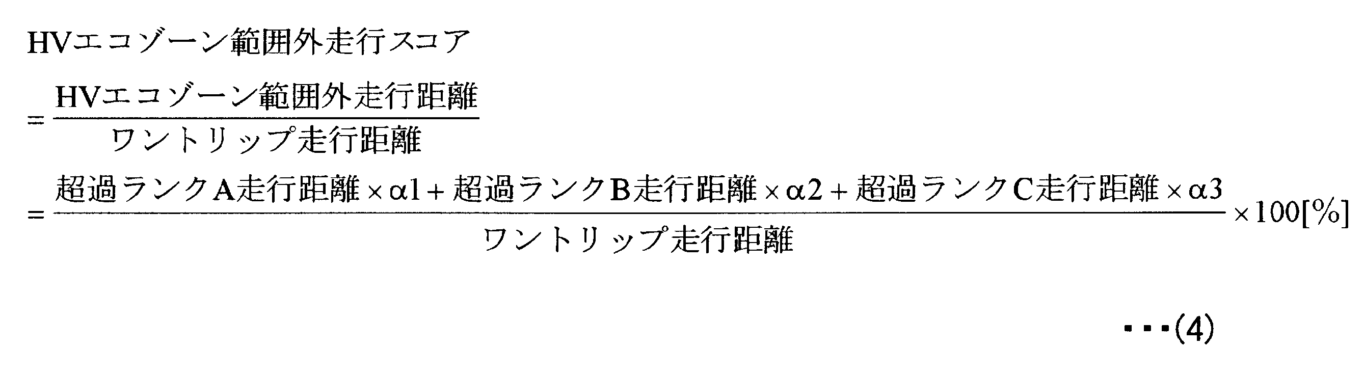
エコランプ点灯走行スコア及びHVエコゾーン範囲内走行スコアは、運転者が省燃費運転を行ったことを評価する“良い”スコアである。一方、HVエコゾーン範囲外走行スコアは、運転者が省燃費運転を怠ったことを量る“悪い”スコアである。
The eco lamp lighting running score and the running score within the HV eco zone range are “good” scores for evaluating that the driver has performed fuel-saving driving. On the other hand, the HV eco-zone out-of-range driving score is a “bad” score that measures that the driver has neglected fuel-saving driving.
そして、省燃費運転採点部12は、図14に例示するように、エコランプ点灯走行スコア、HVエコゾーン範囲内走行スコア及びHVエコゾーン範囲外走行スコアを表示部16cに表示させる。なお、“良い”スコアを加点材料とし、“悪い”スコアを減点材料して総合得点を算出する様にしてもよい。
Then, as shown in FIG. 14, the fuel-saving driving scoring unit 12 causes the display unit 16c to display the eco lamp lighting travel score, the travel score within the HV eco zone range, and the travel score outside the HV eco zone range. Note that the total score may be calculated by using a “good” score as a scoring material and a “bad” score as a scoring material.
以上のように、各走行距離に基づいて各スコアを算出して運転者の省燃費運転度を採点することによって、公平かつ明瞭で納得性の高い採点結果を運転者に提示することができる。
As described above, by calculating each score based on each mileage and scoring the driver's fuel-saving driving degree, it is possible to present the driver with a fair, clear and highly satisfactory scoring result.
省燃費運転診断装置10aの省燃費運転アドバイス生成部13は、エコランプ点灯走行スコア及びHVエコゾーン範囲内走行スコアに応じて、図8に例示する省燃費運転アドバイスを表示部16cに表示させる。また、省燃費運転アドバイス生成部13は、HVエコゾーン範囲外走行スコアに応じて、図9に例示する省燃費運転アドバイスを表示部16cに表示させる。なお、図15及び図16は、表示部16cに省燃費運転アドバイスを表示させた表示態様の一例を示す図である。
The fuel-saving driving advice generation unit 13 of the fuel-saving driving diagnosis device 10a displays the fuel-saving driving advice illustrated in FIG. 8 on the display unit 16c according to the eco lamp lighting driving score and the driving score within the HV eco zone range. Further, the fuel-saving driving advice generation unit 13 displays the fuel-saving driving advice illustrated in FIG. 9 on the display unit 16c according to the HV eco-zone out-of-range driving score. 15 and 16 are diagrams illustrating an example of a display mode in which fuel-saving driving advice is displayed on the display unit 16c.
若しくは、省燃費運転アドバイス生成部13は、エコランプ点灯走行スコア、HVエコゾーン範囲内走行スコア及びHVエコゾーン範囲外走行スコアに応じて、テンプレートメッセージから各スコアに即応したメッセージを生成することとしてもよい。
Alternatively, the fuel-saving driving advice generation unit 13 may generate a message that immediately responds to each score from the template message according to the eco lamp lighting running score, the running score within the HV eco zone range, and the running score outside the HV eco zone range.
次に、省燃費運転診断装置10aの省燃費運転診断部11で実行される省燃費運転診断処理について説明する。図10は、省燃費運転診断処理手順を示すフローチャートである。なお、本処理は、例えば100ミリ秒毎に実行される処理である。同図に示すように、先ず、診断条件管理部11aは、HV走行制御装置20aから、車速、車速パルスセンサ積算値、アクセル開度、シフトレバー位置及びシフトモード状態、要求トルク及びHVエコゾーン情報を取得する(ステップS101)。
Next, the fuel-saving driving diagnosis process executed by the fuel-saving driving diagnosis unit 11 of the fuel-saving driving diagnosis device 10a will be described. FIG. 10 is a flowchart showing a fuel-saving driving diagnosis processing procedure. This process is a process executed every 100 milliseconds, for example. As shown in the figure, first, the diagnostic condition management unit 11a obtains vehicle speed, vehicle speed pulse sensor integrated value, accelerator opening, shift lever position and shift mode state, required torque, and HV eco-zone information from the HV travel control device 20a. Obtain (step S101).
続いて、走行距離積算部11eは、前回取得の車速パルスセンサ積算値と、今回取得の車速パルスセンサ積算値との差分から、100msec走行距離を算出する(ステップS102)。続いて、走行距離積算部11eは、ワントリップ走行距離に、ステップS102で算出された100msec走行距離を加算する(ステップS103)。
Subsequently, the travel distance integrating unit 11e calculates a 100 msec travel distance from the difference between the previously acquired vehicle speed pulse sensor integrated value and the currently acquired vehicle speed pulse sensor integrated value (step S102). Subsequently, the travel distance integrating unit 11e adds the 100 msec travel distance calculated in step S102 to the one-trip travel distance (step S103).
続いて、エコゾーン情報算出部11bは、車種情報に基づき車速毎のエコゾーン情報を算出する(ステップS104)。続いて、診断条件管理部11aは、地図情報DB17aから地図情報を取得する(ステップS105)。
Subsequently, the eco zone information calculation unit 11b calculates the eco zone information for each vehicle speed based on the vehicle type information (step S104). Subsequently, the diagnostic condition management unit 11a acquires map information from the map information DB 17a (step S105).
続いて、診断条件管理部11aは、取得した地図情報に基づいて、車両の現在位置は診断条件を変更する必要がある地点であるか否かを判定する(ステップS106)。診断条件を変更する必要がある地点であると判定された場合に(ステップS106肯定)、ステップS107へ移り、診断条件を変更する必要がある地点であると判定されなかった場合に(ステップS106否定)、ステップS108へ移る。
Subsequently, based on the acquired map information, the diagnosis condition management unit 11a determines whether or not the current position of the vehicle is a point where the diagnosis condition needs to be changed (step S106). When it is determined that the point needs to be changed (Yes in Step S106), the process proceeds to Step S107, and when it is not determined that the point needs to be changed (No in Step S106). ), The process proceeds to step S108.
ステップS107では、診断条件管理部11aは、取得した地図情報に基づいて、省燃費運転の診断条件を変更する。続いて、ステップS108では、車両パワー表示状態量算出判定部11cは、車両パワー表示状態量を算出し、車両パワー表示状態量表示部16aに表示する。
In step S107, the diagnostic condition management unit 11a changes the diagnostic conditions for fuel-saving driving based on the acquired map information. Subsequently, in step S108, the vehicle power display state quantity calculation determination unit 11c calculates a vehicle power display state quantity and displays it on the vehicle power display state quantity display unit 16a.
続いて、エコランプ点灯判定部11dは、エコランプ点灯判定処理を実行する(ステップS109)。エコランプ点灯判定処理の詳細は、図11を参照して後述する。
Subsequently, the eco lamp lighting determination unit 11d executes an eco lamp lighting determination process (step S109). Details of the eco lamp lighting determination process will be described later with reference to FIG.
続いて、車両パワー表示状態量算出判定部11cは、エコランプ16bが点灯、かつ、車両パワー表示状態量がHVエコゾーンの範囲内であるか否かを判定する(ステップS110)。エコランプ16bが点灯、かつ、車両パワー表示状態量がHVエコゾーンの範囲内であると判定された場合に(ステップS110肯定)、ステップS111へ移り、エコランプ16bが点灯、かつ、車両パワー表示状態量がHVエコゾーンの範囲内であると判定されなかった場合に(ステップS110否定)、ステップS112へ移る。
Subsequently, the vehicle power display state quantity calculation determination unit 11c determines whether or not the eco lamp 16b is turned on and the vehicle power display state quantity is within the range of the HV eco zone (step S110). When it is determined that the eco lamp 16b is lit and the vehicle power display state quantity is within the range of the HV eco zone (Yes in step S110), the process proceeds to step S111, the eco lamp 16b is lit, and the vehicle power display state quantity is When it is not determined that it is within the range of the HV eco-zone (No at Step S110), the process proceeds to Step S112.
ステップS111では、走行距離積算部11eは、HVエコゾーン範囲内走行距離に、ステップS102で算出した100msec走行距離を加算する。この処理が終了すると、省燃費運転診断処理は終了する。
In step S111, the travel distance integrating unit 11e adds the travel distance calculated in step S102 to the travel distance within the HV eco-zone range. When this process ends, the fuel-saving driving diagnosis process ends.
ステップS112では、車両パワー表示状態量算出判定部11cは、車両パワー表示状態量がHVエコゾーンの範囲内であるか否かを判定する。車両パワー表示状態量がHVエコゾーンの範囲内であると判定された場合に(ステップS112肯定)、省燃費運転診断処理は終了する。車両パワー表示状態量がHVエコゾーンの範囲内であると判定されなかった場合に(ステップS112否定)、HVエコゾーン範囲外走行距離に、ステップS102で算出した100msec走行距離を加算する(ステップS113)。この処理が終了すると、省燃費運転診断処理は終了する。
In step S112, the vehicle power display state quantity calculation determination unit 11c determines whether or not the vehicle power display state quantity is within the range of the HV eco zone. When it is determined that the vehicle power display state quantity is within the range of the HV eco zone (Yes at step S112), the fuel-saving driving diagnosis process ends. When it is not determined that the vehicle power display state quantity is within the range of the HV eco zone (No at step S112), the 100 msec travel distance calculated at step S102 is added to the travel distance outside the HV eco zone (step S113). When this process ends, the fuel-saving driving diagnosis process ends.
次に、図10のステップS109で示したエコランプ点灯判定処理について説明する。図11は、エコランプ点灯判定処理手順を示すフローチャートである。同図に示すように、先ず、エコランプ点灯判定部11dは、エコランプ点灯フラグをオンに初期化する(ステップS121)。
Next, the eco lamp lighting determination process shown in step S109 of FIG. 10 will be described. FIG. 11 is a flowchart showing an eco lamp lighting determination processing procedure. As shown in the figure, first, the eco lamp lighting determining unit 11d initializes the eco lamp lighting flag to on (step S121).
続いて、エコランプ点灯判定部11dは、車速は診断条件値の範囲内か否かを判定する(ステップS122)。車速は診断条件値の範囲内であると判定された場合に(ステップS122肯定)、ステップS123へ移り、車速は診断条件値の範囲内であると判定されなかった場合に(ステップS122否定)、ステップS126へ移る。
Subsequently, the eco lamp lighting determining unit 11d determines whether or not the vehicle speed is within the range of the diagnostic condition value (step S122). When it is determined that the vehicle speed is within the range of the diagnostic condition value (Yes at Step S122), the process proceeds to Step S123. When the vehicle speed is not determined to be within the range of the diagnostic condition value (No at Step S122), Control goes to step S126.
続いて、エコランプ点灯判定部11dは、アクセル開度は診断条件値の範囲内か否かを判定する(ステップS123)。アクセル開度は診断条件値の範囲内であると判定された場合に(ステップS123肯定)、ステップS124へ移り、アクセル開度は診断条件値の範囲内であると判定されなかった場合に(ステップS123否定)、ステップS126へ移る。
Subsequently, the eco lamp lighting determination unit 11d determines whether or not the accelerator opening is within the range of the diagnostic condition value (step S123). When it is determined that the accelerator opening is within the range of the diagnostic condition value (Yes at Step S123), the process proceeds to Step S124, and when the accelerator opening is not determined to be within the range of the diagnostic condition value (Step S123). (No in S123), the process proceeds to step S126.
続いて、エコランプ点灯判定部11dは、シフトレバー位置は診断条件値を充足するか否かを判定する(ステップS124)。シフトレバー位置は診断条件値を充足すると判定された場合に(ステップS124肯定)、ステップS125へ移り、シフトレバー位置は診断条件値を充足すると判定されなかった場合に(ステップS124否定)、ステップS126へ移る。
Subsequently, the eco lamp lighting determining unit 11d determines whether or not the shift lever position satisfies the diagnostic condition value (step S124). If it is determined that the shift lever position satisfies the diagnostic condition value (Yes at Step S124), the process proceeds to Step S125. If the shift lever position is not determined to satisfy the diagnostic condition value (No at Step S124), Step S126 is performed. Move on.
続いて、エコランプ点灯判定部11dは、シフトモード状態は診断条件値を充足するか否かを判定する(ステップS125)。シフトモード状態は診断条件値を充足すると判定された場合に(ステップS125肯定)、ステップS127へ移り、シフトレバー位置は診断条件値を充足すると判定されなかった場合に(ステップS125否定)、ステップS126へ移る。
Subsequently, the eco lamp lighting determining unit 11d determines whether or not the shift mode state satisfies the diagnostic condition value (step S125). If it is determined that the shift mode state satisfies the diagnostic condition value (Yes at Step S125), the process proceeds to Step S127. If the shift lever position is not determined to satisfy the diagnostic condition value (No at Step S125), Step S126 is performed. Move on.
ステップS126では、エコランプ点灯判定部11dは、エコランプ点灯フラグをオフにする。続いて、ステップS127では、エコランプ点灯判定部11dは、エコランプ点灯フラグはオンか否かを判定する。エコランプ点灯フラグはオンであると判定された場合に(ステップS127肯定)、エコランプ点灯判定部11dは、エコランプ16bを点灯し(ステップS128)、エコランプ点灯走行距離に、図10のステップS102で算出された100msec走行距離を加算する(ステップS129)。
In step S126, the eco lamp lighting determining unit 11d turns off the eco lamp lighting flag. Subsequently, in step S127, the eco lamp lighting determining unit 11d determines whether or not the eco lamp lighting flag is on. When it is determined that the eco lamp lighting flag is on (Yes at step S127), the eco lamp lighting determining unit 11d lights the eco lamp 16b (step S128), and the eco lamp lighting travel distance is calculated in step S102 of FIG. The 100 msec travel distance is added (step S129).
なお、エコランプ点灯フラグはオンであると判定されなかった場合に(ステップS127否定)、エコランプ点灯判定処理は終了する。
If it is not determined that the eco lamp lighting flag is on (No at step S127), the eco lamp lighting determination process ends.
なお、図10に示した省燃費運転診断処理では、車両の現在位置が診断条件を変更する必要がある地点では診断条件を変更して省燃費運転診断を行うものである。一方、同一の処理には同一のステップ番号を付与することとして、図12に示すように、ステップS102の次にステップS104を実行し、ステップS103は、ステップS106の判定が肯定の場合に実行されることとしてもよい。ステップS103の実行以降は、ステップS108~ステップS113が実行される。また、ステップS106の判定が否定の場合は、直ちに省燃費運転診断処理する。
In the fuel-saving driving diagnosis process shown in FIG. 10, the fuel-saving driving diagnosis is performed by changing the diagnostic condition at a point where the current position of the vehicle needs to change the diagnostic condition. On the other hand, the same step number is assigned to the same process, and as shown in FIG. 12, step S104 is executed after step S102, and step S103 is executed when the determination in step S106 is affirmative. It is also good to do. After execution of step S103, steps S108 to S113 are executed. If the determination in step S106 is negative, the fuel-saving driving diagnosis process is immediately performed.
すなわち、図12に示す省燃費運転診断処理では、車両の現在位置が診断条件を変更する必要がある地点では診断自体を行わず、ワントリップ走行距離及びHVエコゾーン範囲内走行距離のいずれにも100msec走行距離を加算しない。このようにしても、車両1aの走行条件や交通状況を加味した公平な省燃費運転診断を行うことができる。
That is, in the fuel-saving driving diagnosis process shown in FIG. 12, the diagnosis itself is not performed at the point where the current position of the vehicle needs to change the diagnosis condition, and both the one-trip travel distance and the travel distance within the HV eco-zone range are 100 msec. Do not add mileage. Even in this way, it is possible to perform a fair fuel-saving driving diagnosis in consideration of the traveling conditions and traffic conditions of the vehicle 1a.
次に、省燃費運転診断装置10aの省燃費運転採点部12及び省燃費運転アドバイス生成部13で実行される省燃費運転採点結果アドバイス通知処理について説明する。図13は、省燃費運転採点結果アドバイス通知処理手順を示すフローチャートである。同図に示すように、先ず、省燃費運転採点部12は、ワントリップ走行終了か否かを判定する(ステップS201)。ワントリップ走行終了と判定された場合に(ステップS201肯定)、ステップS202へ移り、ワントリップ走行終了と判定されなかった場合(ステップS201否定)にステップS201を繰り返す。
Next, the fuel-saving driving scoring result advice notification process executed by the fuel-saving driving scoring unit 12 and the fuel-saving driving advice generating unit 13 of the fuel-saving driving diagnostic device 10a will be described. FIG. 13 is a flowchart showing a fuel-saving driving scoring result advice notification processing procedure. As shown in the figure, first, the fuel-saving driving scoring unit 12 determines whether or not the one-trip running is finished (step S201). When it is determined that the one-trip travel is finished (Yes at Step S201), the process proceeds to Step S202, and when it is not determined that the one-trip travel is finished (No at Step S201), Step S201 is repeated.
ステップS202では、省燃費運転採点部12は、エコランプ点灯スコア、HVエコゾーン範囲内走行スコア及びHVエコゾーン範囲外走行スコアを、上記(2)~(4)式に基づいてそれぞれ算出する。
In step S202, the fuel-saving driving scoring unit 12 calculates the eco lamp lighting score, the HV eco-zone range running score, and the HV eco-zone range running score based on the above equations (2) to (4), respectively.
続いて、省燃費運転採点部12は、ステップS202の処理によって算出された各スコアを表示部16cに表示させる(ステップS203)。続いて、省燃費運転アドバイス生成部13は、エコランプ点灯スコア、HVエコゾーン範囲内走行スコア、HVエコゾーン範囲外走行スコアそれぞれに対応する省燃費運転の意識向上を促すアドバイスメッセージを表示部16cに表示させる(ステップS204)。この処理が終了すると、省燃費運転採点結果アドバイス通知処理は終了する。
Subsequently, the fuel-saving driving scoring unit 12 displays each score calculated by the process of step S202 on the display unit 16c (step S203). Subsequently, the fuel-saving driving advice generation unit 13 causes the display unit 16c to display an advice message for promoting awareness of fuel-saving driving corresponding to each of the eco lamp lighting score, the HV eco-zone range running score, and the HV eco-zone range running score. (Step S204). When this process ends, the fuel-saving driving scoring result advice notification process ends.
以上の様に、運転者に対して採点結果及び省燃費運転アドバイスを表示することによって、省燃費運転を心がける意識の喚起と向上とを図ることができ、延いてはハイブリッドカーが有する環境性能を十分に引き出す運転を行わせることができる。
As described above, by displaying scoring results and fuel-saving driving advice to the driver, it is possible to raise awareness and improve fuel-saving driving, and to improve the environmental performance of hybrid cars. It is possible to perform a driving operation sufficiently.
なお、図17に車両1bの省燃費運転診断装置10b及びHV走行制御装置20bの構成を示すように、図3に示した車両1aの省燃費運転診断装置10aの省燃費運転診断部11を有する構成に代えて、HV走行制御装置20bが省燃費運転診断部22を有する構成であってもよい。この場合、省燃費運転診断装置及びHV走行制御装置の構成が変わるのみで、他は上記実施形態の一例と同様である。このような構成にすると、省燃費運転診断装置10bの構成を簡略化し、処理負担を軽減することができる。
In addition, as shown in FIG. 17, the fuel-saving driving diagnosis device 10 b and the HV traveling control device 20 b of the vehicle 1 b have the fuel-saving driving diagnosis unit 11 of the fuel-saving driving diagnosis device 10 a of the vehicle 1 a shown in FIG. 3. Instead of the configuration, the HV traveling control device 20b may have a fuel-saving driving diagnosis unit 22. In this case, only the configurations of the fuel-saving driving diagnosis device and the HV traveling control device are changed, and the rest is the same as the example of the embodiment. With such a configuration, the configuration of the fuel-saving driving diagnosis device 10b can be simplified and the processing load can be reduced.
なお、省燃費運転診断部22が有する診断条件管理部22a、エコゾーン情報算出部22b、車両パワー表示状態量算出判定部22c、エコランプ点灯判定部22d、走行距離積算部22eは、省燃費診断部11が有する診断条件管理部11a、エコゾーン情報算出部11b、車両パワー表示状態量算出判定部11c、エコランプ点灯判定部11d、走行距離積算部11eとそれぞれ同一の機能構成である。なお、エコランプ点灯判定部22d及び/又は走行距離積算部22eは、省燃費運転診断部22ではなく省燃費運転診断装置10bに含まれる構成であってもよい。
The fuel-saving driving diagnosis unit 22 includes a diagnosis condition management unit 22a, an eco-zone information calculation unit 22b, a vehicle power display state quantity calculation determination unit 22c, an eco-lamp lighting determination unit 22d, and a travel distance integration unit 22e. Have the same functional configuration as the diagnostic condition management unit 11a, eco zone information calculation unit 11b, vehicle power display state quantity calculation determination unit 11c, eco lamp lighting determination unit 11d, and travel distance integration unit 11e. The eco lamp lighting determining unit 22d and / or the travel distance integrating unit 22e may be included in the fuel-saving driving diagnosis device 10b instead of the fuel-saving driving diagnosis unit 22.
以上、本発明の実施形態の一例を説明したが、本発明は、これに限られるものではなく、特許請求の範囲に記載した技術的思想の範囲内で、更に種々の異なる実施形態で実施されてもよいものである。また、実施形態の一例に記載した効果は、これに限定されるものではない。
Although an example of the embodiment of the present invention has been described above, the present invention is not limited to this, and can be implemented in various different embodiments within the scope of the technical idea described in the claims. It may be. Moreover, the effect described in an example of embodiment is not limited to this.
具体的には、エコランプ16bの点灯を前提とせず、車両パワー表示状態量の診断及び採点を行うこととしてもよい。また、登坂又は下阪走行に際し、平地走行より車両1aにより多くかかる重力に関してのみ車両パワー表示状態量の診断条件を変更するのみでよいとすれば、地図情報DB17aに代えて重力センサを採用することができる。
Specifically, diagnosis and scoring of the vehicle power display state quantity may be performed without assuming that the eco lamp 16b is turned on. In addition, when traveling uphill or downhill, if it is only necessary to change the diagnostic condition of the vehicle power display state quantity for the gravity applied to the vehicle 1a more than the flat ground traveling, a gravity sensor is employed instead of the map information DB 17a. Can do.
また、車両への乗車人数による重量、積載貨物重量等を加味して車両パワー表示状態量の診断条件値を変更して車両パワー表示状態量の診断及び採点を行うこととしてもよい。
In addition, diagnosis and scoring of the vehicle power display state quantity may be performed by changing the diagnosis condition value of the vehicle power display state quantity in consideration of the weight depending on the number of passengers in the vehicle, the loaded cargo weight, and the like.
また、充電電力だけを使用して要求トルクがHVエコゾーン範囲内の走行を行った場合に、スコアを上乗せして採点を行うようにしてもよい。また、要求トルク発生に係る充電電力の使用割合に応じてスコアの重み付けを変化させて採点するようにしてもよい。
Further, when the required torque is traveled within the HV eco-zone range using only the charging power, the score may be added and the scoring may be performed. Further, scoring may be performed by changing the weighting of the score in accordance with the usage rate of the charging power related to the required torque generation.
また、車両の運転者に採点結果やアドバイスを通知する通知方法は、表示部16cへの表示に限らず、音響や音声を使用する通知方法であってもよい。
Further, the notification method for notifying the driver of the vehicle of the scoring result and advice is not limited to the display on the display unit 16c, and may be a notification method using sound or voice.
上記実施形態の一例によれば、省燃費運転診断の診断条件を、車両の走行条件を加味して緩和したり厳格化したりするので、省燃費運転診断の診断精度を高め、延いては省燃費運転の採点の精度を高めることができる。
According to an example of the above-described embodiment, the diagnosis conditions for the fuel-saving driving diagnosis are relaxed or tightened in consideration of the driving conditions of the vehicle. The accuracy of driving scoring can be increased.
また、上記実施形態の一例では、予め定められている省燃費運転診断条件を道路状況、交通状況、路面状況又は気象条件等に基づいて条件緩和又は条件厳格化を行って公正な省燃費運転診断を行うこととした。しかし、これに限らず、道路状況、交通状況、路面状況又は気象条件等に基づいて省燃費運転診断条件を生成し、生成された省燃費運転診条件に基づいて省燃費運転診断を行うこととしてもよい。また、さらに生成された省燃費運転診条件から適切な省燃費運転診条件を選択して、選択された省燃費運転診条件に基づいて省燃費運転診断を行うこととしてもよい。これによって、固定的な省燃費運転診条件ではなく、状況に応じた柔軟な省燃費運転診条件に基づいて、より公正な省燃費運転診断を行うことが可能になる。
In one example of the above-described embodiment, the fuel-saving driving diagnosis conditions that have been determined in advance are relaxed or stricter based on road conditions, traffic conditions, road surface conditions, weather conditions, etc. It was decided to do. However, the present invention is not limited thereto, and fuel-saving driving diagnosis conditions are generated based on road conditions, traffic conditions, road surface conditions, weather conditions, etc., and fuel-saving driving diagnosis is performed based on the generated fuel-saving driving diagnosis conditions. Also good. Further, an appropriate fuel-saving driving diagnosis condition may be selected from the generated fuel-saving driving diagnosis conditions, and fuel-saving driving diagnosis may be performed based on the selected fuel-saving driving diagnosis conditions. This makes it possible to perform a more fair fuel-saving driving diagnosis based on the flexible fuel-saving driving diagnosis conditions according to the situation rather than the fixed fuel-saving driving diagnosis conditions.
上記実施形態の一例において説明した各処理のうち、自動的におこなわれるものとして説明した処理の全部又は一部を手動的におこなうこともでき、或いは、手動的におこなわれるものとして説明した処理の全部又は一部を公知の方法で自動的におこなうこともできる。この他、上記実施形態の一例で示した処理手順、制御手順、具体的名称、各種のデータやパラメータを含む情報については、特記する場合を除いて任意に変更することが可能である。
Among the processes described in the example of the embodiment, all or part of the processes described as being automatically performed can be manually performed, or the processes described as being manually performed can be performed. All or a part can be automatically performed by a known method. In addition, the processing procedure, control procedure, specific name, and information including various data and parameters shown in the example of the above embodiment can be arbitrarily changed unless otherwise specified.
また、図示した各装置の各構成要素は機能概念的なものであり、必ずしも物理的に図示のように構成されていることを要しない。すなわち、各装置の分散又は統合の具体的形態は図示のものに限られず、その全部または一部を、各種の負荷や使用状況などに応じて、任意の単位で機能的若しくは物理的に分散又は統合して構成することができる。
Further, each component of each illustrated apparatus is functionally conceptual and does not necessarily need to be physically configured as illustrated. In other words, the specific form of distribution or integration of each device is not limited to that shown in the figure, and all or a part thereof may be functionally or physically distributed or arbitrarily distributed in arbitrary units according to various loads or usage conditions. Can be integrated and configured.
さらに、各装置にて行なわれる各処理機能は、その全部又は任意の一部が、CPU(Central Processing Unit)(若しくはMPU(Micro Processing Unit)、MCU(Micro Controller Unit)等のマイクロ・コンピュータ)及びCPU(若しくはMPU、MCU等のマイクロ・コンピュータ)にて解析実行されるプログラムにて実現され、或いは、ワイヤードロジックによるハードウェアとして実現されてもよい。
Furthermore, all or any part of each processing function performed by each device is a CPU (Central Processing Unit) (or a microcomputer such as an MPU (Micro Processing Unit) or MCU (Micro Controller Unit)) and It may be realized by a program that is analyzed and executed by a CPU (or a microcomputer such as an MPU or MCU), or may be realized as hardware by wired logic.
開示の省燃費運転診断装置、省燃費運転診断システム及び省燃費運転診断方法は、車両の運転者の運転がどれだけエコ的であるかを診断し、診断結果に基づいて採点し、採点結果及び採点結果に基づく省燃費運転アドバイスを運転者にフィードバックすることによって、運転者の省燃費運転意識の向上、特に加減速が省燃費運転となる様に意識を向上させたい場合に有用である。
The disclosed fuel-saving driving diagnosis device, fuel-saving driving diagnosis system, and fuel-saving driving diagnosis method diagnose how ecologically the driving of a vehicle driver is, scoring based on the diagnosis result, scoring result and This is useful for improving the driver's awareness of fuel-saving driving, particularly when he / she wants to raise his / her consciousness so that acceleration / deceleration becomes fuel-saving driving by feeding the driver fuel-saving driving advice based on the scoring results.
1a、1b 車両
10a、10b 省燃費運転診断装置
11 省燃費運転診断部
11a 診断条件管理部
11b エコゾーン情報算出部
11c 車両パワー表示状態量算出判定部
11d エコランプ点灯判定部
11e 走行距離積算部
12 省燃費運転採点部
13 省燃費運転アドバイス生成部
14 車載ネットワークインターフェース部
15 出力インターフェース部
16a 車両パワー表示状態量表示部
16b エコランプ
16c 表示部
17 カーナビゲーション装置
17a 地図情報DB
18 道路情報受信装置
20a、20b HV走行制御装置
21a 要求トルク算出部
21b HVエコゾーン情報算出部
21c モータ特性情報管理部
21d 車種情報管理部
22 省燃費運転診断部
22a 診断条件管理部
22b エコゾーン情報算出部
22c 車両パワー表示状態量算出判定部
22d エコランプ点灯判定部
22e 走行距離積算部
23 電池監視装置
24a エンジン制御装置
24b モータ制御装置
25 ブレーキ制御装置
26 車速センサ
27 アクセル操作量センサ
28 シフトセンサ
29 車速パルス信号積算値格納部
100 車載ネットワーク
501 エコゾーン
502 HVエコゾーン
503 最大表示状態量
504 車両パワー表示状態量非エコゾーン
505 車両パワー表示状態量 1a, 1b Vehicles 10a, 10b Fuel saving driving diagnosis device 11 Fuel saving driving diagnosis unit 11a Diagnosis condition management unit 11b Eco zone information calculation unit 11c Vehicle power display state quantity calculation determination unit 11d Eco lamp lighting determination unit 11e Travel distance integration unit 12 Fuel consumption saving Driving scoring unit 13 Fuel-saving driving advice generating unit 14 In-vehicle network interface unit 15 Output interface unit 16a Vehicle power display state quantity display unit 16b Eco lamp 16c Display unit 17 Car navigation device 17a Map information DB
18 Road information receiving device 20a, 20b HV travel control device 21a Required torque calculation unit 21b HV eco zone information calculation unit 21c Motor characteristic information management unit 21d Vehicle type information management unit 22 Fuel-saving driving diagnosis unit 22a Diagnosis condition management unit 22b Eco zone information calculation unit 22c Vehicle power display state quantity calculation determination unit 22d Eco lamp lighting determination unit 22e Travel distance integration unit 23 Battery monitoring device 24a Engine control device 24b Motor control device 25 Brake control device 26 Vehicle speed sensor 27 Accelerator operation amount sensor 28 Shift sensor 29 Vehicle speed pulse signal Integrated value storage unit 100 In-vehicle network 501 Eco zone 502 HV eco zone 503 Maximum display state quantity 504 Vehicle power display state quantity Non-eco zone 505 Vehicle power display state quantity
10a、10b 省燃費運転診断装置
11 省燃費運転診断部
11a 診断条件管理部
11b エコゾーン情報算出部
11c 車両パワー表示状態量算出判定部
11d エコランプ点灯判定部
11e 走行距離積算部
12 省燃費運転採点部
13 省燃費運転アドバイス生成部
14 車載ネットワークインターフェース部
15 出力インターフェース部
16a 車両パワー表示状態量表示部
16b エコランプ
16c 表示部
17 カーナビゲーション装置
17a 地図情報DB
18 道路情報受信装置
20a、20b HV走行制御装置
21a 要求トルク算出部
21b HVエコゾーン情報算出部
21c モータ特性情報管理部
21d 車種情報管理部
22 省燃費運転診断部
22a 診断条件管理部
22b エコゾーン情報算出部
22c 車両パワー表示状態量算出判定部
22d エコランプ点灯判定部
22e 走行距離積算部
23 電池監視装置
24a エンジン制御装置
24b モータ制御装置
25 ブレーキ制御装置
26 車速センサ
27 アクセル操作量センサ
28 シフトセンサ
29 車速パルス信号積算値格納部
100 車載ネットワーク
501 エコゾーン
502 HVエコゾーン
503 最大表示状態量
504 車両パワー表示状態量非エコゾーン
505 車両パワー表示状態量 1a,
18 Road
Claims (12)
- 電気をエネルギーとして車両を駆動する電気駆動装置を有する車両の省燃費運転を診断する省燃費運転診断装置であって、
前記電気駆動装置の車両走行に関する制御値で求められる省燃費運転条件を、前記電気駆動装置の性能特性と前記車両の車速とに基づいて算出する省燃費運転条件算出部と、
前記電気駆動装置の車両走行に関する制御値を取得する制御値取得部と、
前記制御値取得部により取得された制御値が前記省燃費運転条件算出部により算出された省燃費運転条件を充足するか否かを判定する省燃費運転判定部と
を有することを特徴とする省燃費運転診断装置。 A fuel-saving driving diagnosis device that diagnoses fuel-saving driving of a vehicle having an electric drive device that drives the vehicle using electricity as energy,
A fuel-saving driving condition calculation unit that calculates a fuel-saving driving condition determined by a control value related to vehicle travel of the electric drive device based on performance characteristics of the electric drive device and a vehicle speed of the vehicle;
A control value acquisition unit for acquiring a control value related to vehicle travel of the electric drive device;
A fuel-saving driving determination unit that determines whether or not the control value acquired by the control value acquisition unit satisfies the fuel-saving driving condition calculated by the fuel-saving driving condition calculation unit. Fuel consumption diagnosis system. - 前記省燃費運転条件算出部は、道路状況又は交通状況を取得する道路交通状況取得装置により取得された前記道路状況又は前記交通状況に応じて前記省燃費運転条件を変更することを特徴とする請求項1記載の省燃費運転診断装置。 The fuel-saving driving condition calculation unit changes the fuel-saving driving condition according to the road condition or the traffic condition acquired by a road traffic condition acquisition device that acquires a road condition or a traffic condition. Item 1. The fuel-saving driving diagnosis device according to Item 1.
- 前記省燃費運転判定部は、道路状況又は交通状況を取得する道路交通状況取得装置により取得された前記道路状況又は前記交通状況に応じて、前記制御値取得部により取得された制御値が前記省燃費運転条件算出部により算出された省燃費運転条件を充足するか否かの判定をキャンセルすることを特徴とする請求項1記載の省燃費運転診断装置。 The fuel-saving driving determination unit determines whether the control value acquired by the control value acquisition unit is the saving value according to the road condition or the traffic condition acquired by a road traffic condition acquisition device that acquires a road condition or a traffic condition. The fuel-saving driving diagnosis apparatus according to claim 1, wherein the determination as to whether or not the fuel-saving driving condition calculated by the fuel-saving driving condition calculation unit is satisfied is cancelled.
- 前記制御値が前記省燃費運転条件を充足するか否かを判定する対象である前記車両の判定対象走行距離と、該判定対象走行距離のうち前記省燃費運転判定部により前記省燃費運転条件を充足すると判定された走行距離とに基づいて省燃費運転を採点する省燃費運転採点部を有することを特徴とする請求項1、2又は3記載の省燃費運転診断装置。 The determination target travel distance of the vehicle, which is a target for determining whether or not the control value satisfies the fuel-saving driving condition, and the fuel-saving driving determination unit out of the determination target travel distance, 4. The fuel-saving driving diagnosing device according to claim 1, further comprising a fuel-saving driving scoring unit for scoring fuel-saving driving based on a travel distance determined to be satisfied.
- 前記省燃費運転採点部による採点結果に基づいて省燃費運転アドバイスを生成するアドバイス生成部を有することを特徴とする請求項4記載の省燃費運転診断装置。 The fuel-saving driving diagnosis apparatus according to claim 4, further comprising an advice generation unit that generates fuel-saving driving advice based on a scoring result by the fuel-saving driving scoring unit.
- 前記省燃費運転採点部による採点結果又は前記アドバイス生成部により生成された省燃費運転アドバイスを運転者に通知する通知部を有することを特徴とする請求項5記載の省燃費運転診断装置。 6. The fuel-saving driving diagnosis apparatus according to claim 5, further comprising a notifying unit that notifies a driver of a scoring result by the fuel-saving driving scoring unit or a fuel-saving driving advice generated by the advice generating unit.
- 電気をエネルギーとして車両を駆動する電気駆動装置を有する車両の省燃費運転を診断する省燃費運転診断システムであって、
前記電気駆動装置の車両走行に関する制御値で求められる省燃費運転条件を、前記電気駆動装置の性能特性と前記車両の車速とに基づいて算出する省燃費運転条件算出部と、前記電気駆動装置の車両走行に関する制御値を取得する制御値取得部と、前記制御値取得部により取得された制御値が前記省燃費運転条件算出部により算出された省燃費運転条件を充足するか否かを判定する省燃費運転判定部とを有する前記電気駆動装置の制御装置と、
前記制御値が前記省燃費運転条件を充足するか否かを判定する対象である前記車両の判定対象走行距離と、該判定対象走行距離のうち前記省燃費運転判定部により前記省燃費運転条件を充足すると判定された走行距離とに基づいて省燃費運転を採点する省燃費運転採点部を有する省燃費運転採点装置と
を含むことを特徴とする省燃費運転診断システム。 A fuel-saving driving diagnosis system that diagnoses fuel-saving driving of a vehicle having an electric drive device that drives the vehicle using electricity as energy,
A fuel-saving driving condition calculation unit that calculates a fuel-saving driving condition determined by a control value related to vehicle travel of the electric drive device based on performance characteristics of the electric drive device and a vehicle speed of the vehicle; and A control value acquisition unit that acquires a control value related to vehicle traveling, and determines whether or not the control value acquired by the control value acquisition unit satisfies the fuel-saving driving condition calculated by the fuel-saving driving condition calculation unit A control device for the electric drive device having a fuel-saving drive determination unit;
The determination target travel distance of the vehicle, which is a target for determining whether or not the control value satisfies the fuel-saving driving condition, and the fuel-saving driving determination unit out of the determination target travel distance, A fuel-saving driving scoring system comprising: a fuel-saving driving scoring unit having a fuel-saving driving scoring unit that scores fuel-saving driving based on a travel distance determined to be satisfied. - 前記省燃費運転条件算出部は、道路状況又は交通状況を取得する道路交通状況取得装置により取得された前記道路状況又は前記交通状況に応じて前記省燃費運転条件を変更することを特徴とする請求項7記載の省燃費運転診断システム。 The fuel-saving driving condition calculation unit changes the fuel-saving driving condition according to the road condition or the traffic condition acquired by a road traffic condition acquisition device that acquires a road condition or a traffic condition. Item 8. The fuel-saving driving diagnosis system according to Item 7.
- 前記省燃費運転判定部は、道路状況又は交通状況を取得する道路交通状況取得装置により取得された前記道路状況又は前記交通状況に応じて、前記制御値取得部により取得された制御値が前記省燃費運転条件算出部により算出された省燃費運転条件を充足するか否かの判定をキャンセルすることを特徴とする請求項7記載の省燃費運転診断システム。 The fuel-saving driving determination unit determines whether the control value acquired by the control value acquisition unit is the saving value according to the road condition or the traffic condition acquired by a road traffic condition acquisition device that acquires a road condition or a traffic condition. 8. The fuel-saving driving diagnosis system according to claim 7, wherein the determination as to whether or not the fuel-saving driving condition calculated by the fuel consumption driving condition calculation unit is satisfied is canceled.
- 電気をエネルギーとして車両を駆動する電気駆動装置を制御するとともに車両の省燃費運転を診断する前記電気駆動装置の制御装置であって、
前記電気駆動装置の車両走行に関する制御値で求められる省燃費運転条件を、前記電気駆動装置の性能特性と前記車両の車速とに基づいて算出する省燃費運転条件算出部と、
前記電気駆動装置の車両走行に関する制御値を取得する制御値取得部と、
前記制御値取得部により取得された制御値が前記省燃費運転条件算出部により算出された省燃費運転条件を充足するか否かを判定する省燃費運転判定部と
を有することを特徴とする電気駆動装置の制御装置。 A control device for the electric drive device that controls an electric drive device that drives a vehicle using electricity as energy and diagnoses fuel-saving driving of the vehicle,
A fuel-saving driving condition calculation unit that calculates a fuel-saving driving condition determined by a control value related to vehicle travel of the electric drive device based on performance characteristics of the electric drive device and a vehicle speed of the vehicle;
A control value acquisition unit for acquiring a control value related to vehicle travel of the electric drive device;
A fuel-saving driving determination unit that determines whether or not the control value acquired by the control value acquisition unit satisfies the fuel-saving driving condition calculated by the fuel-saving driving condition calculation unit. Control device for driving device. - 電気をエネルギーとして車両を駆動する電気駆動装置を有する車両の省燃費運転を採点する省燃費運転採点装置であって、
省燃費運転を診断する省燃費運転診断装置から取得した前記車両の省燃費運転診断結果に応じて、省燃費運転診断対象走行距離と、該省燃費運転診断対象走行距離のうち前記省燃費運転診断装置により省燃費運転であると診断された走行距離とに基づいて省燃費運転を採点する省燃費運転採点部と、
前記省燃費運転採点部による採点結果に基づいて省燃費運転アドバイスを生成するアドバイス生成部と、
前記省燃費運転採点部による採点結果又は前記アドバイス生成部によって生成された省燃費運転アドバイスを運転者に通知する通知部と
を有することを特徴とする省燃費運転採点装置。 A fuel-saving driving scoring device for scoring fuel-saving driving of a vehicle having an electric drive device that drives the vehicle using electricity as energy,
According to the fuel-saving driving diagnosis result of the vehicle acquired from the fuel-saving driving diagnosis device that diagnoses fuel-saving driving, the fuel-saving driving diagnosis target travel distance and the fuel-saving driving diagnosis among the fuel-saving driving diagnosis target travel distances A fuel-saving driving scoring unit for scoring fuel-saving driving based on the mileage diagnosed as fuel-saving driving by the device;
An advice generating unit that generates fuel-saving driving advice based on the scoring result by the fuel-saving driving scoring unit;
A fuel-saving driving scoring device, comprising: a notifying unit that notifies a driver of a scoring result by the fuel-saving driving scoring unit or a fuel-saving driving advice generated by the advice generating unit. - 電気をエネルギーとして車両を駆動する電気駆動装置を有する車両の省燃費運転の診断を省燃費運転診断システムが行う省燃費運転診断方法であって、
前記電気駆動装置の車両走行に関する制御値で求められる省燃費運転条件を、前記電気駆動装置の性能特性と前記車両の車速とに基づいて算出する省燃費運転条件算出ステップと、
前記電気駆動装置の車両走行に関する制御値を取得する制御値取得ステップと、
前記制御値取得ステップにより取得された制御値が前記省燃費運転条件算出ステップにより算出された省燃費運転条件を充足するか否かを判定する省燃費運転判定ステップと
道路状況又は交通状況を取得する道路交通状況取得ステップと、
前記道路交通状況取得ステップにより取得された道路状況又は交通状況に応じて、前記制御値取得ステップにより取得された制御値が前記省燃費運転条件算出ステップにより算出された省燃費運転条件を充足するか否かを判定する省燃費運転判定ステップと、
前記制御値が前記省燃費運転条件を充足するか否かを判定する対象である前記車両の判定対象走行距離と、該判定対象走行距離のうち前記省燃費運転判定ステップにより前記省燃費運転条件を充足すると判定された走行距離とに基づいて省燃費運転を採点する省燃費運転採点ステップと、
前記省燃費運転採点ステップによる採点結果に基づいて省燃費運転アドバイスを生成するアドバイス生成ステップと、
前記省燃費運転採点ステップによる採点結果及び前記アドバイス生成ステップにより生成された省燃費運転アドバイスを運転者に通知する通知ステップと
を含むことを特徴とする省燃費運転診断方法。 A fuel-saving driving diagnosis method in which a fuel-saving driving diagnosis system diagnoses a fuel-saving driving of a vehicle having an electric drive device that drives the vehicle using electricity as energy,
A fuel-saving driving condition calculating step of calculating a fuel-saving driving condition determined by a control value related to vehicle travel of the electric drive device based on performance characteristics of the electric drive device and a vehicle speed of the vehicle;
A control value acquisition step of acquiring a control value related to vehicle travel of the electric drive device;
A fuel-saving driving determination step for determining whether or not the control value acquired in the control value acquisition step satisfies the fuel-saving driving condition calculated in the fuel-saving driving condition calculation step and a road condition or a traffic condition are acquired. Road traffic status acquisition step;
Whether the control value acquired by the control value acquisition step satisfies the fuel-saving driving condition calculated by the fuel-saving driving condition calculation step according to the road condition or traffic condition acquired by the road traffic condition acquisition step A fuel-saving driving determination step for determining whether or not,
The determination target travel distance of the vehicle, which is a target for determining whether or not the control value satisfies the fuel saving driving condition, and the fuel saving driving condition is determined by the fuel saving driving determination step of the determination target traveling distance. A fuel-saving driving scoring step for scoring fuel-saving driving based on the travel distance determined to be satisfied;
An advice generating step for generating fuel-saving driving advice based on the scoring result of the fuel-saving driving scoring step;
A fuel-saving driving diagnosis method, comprising: a notifying step of notifying a driver of a scoring result of the fuel-saving driving scoring step and a fuel-saving driving advice generated by the advice generating step.
Priority Applications (3)
| Application Number | Priority Date | Filing Date | Title |
|---|---|---|---|
| US13/002,233 US8655527B2 (en) | 2008-07-31 | 2009-07-21 | Fuel-saving driving diagnostic device, fuel-saving driving diagnostic system, control device of electric drive device, fuel-saving driving rating device, and fuel-saving driving diagnostic method |
| CN200980129275.2A CN102105324B (en) | 2008-07-31 | 2009-07-21 | Low fuel consumption driving diagnostic device, low fuel consumption driving diagnostic system, controller for electrical drive device, low fuel consumption driving scoring device, and low fuel consumption driving diagnostic method |
| EP09802860.8A EP2311683B1 (en) | 2008-07-31 | 2009-07-21 | Low fuel consumption driving diagnostic device, low fuel consumption driving diagnostic system, controller for electrical drive device, low fuel consumption driving scoring device, and low fuel consumption driving diagnostic method |
Applications Claiming Priority (2)
| Application Number | Priority Date | Filing Date | Title |
|---|---|---|---|
| JP2008-198382 | 2008-07-31 | ||
| JP2008198382A JP4495234B2 (en) | 2008-07-31 | 2008-07-31 | Fuel saving driving diagnosis device, fuel saving driving diagnosis system and fuel saving driving diagnosis method |
Publications (1)
| Publication Number | Publication Date |
|---|---|
| WO2010013617A1 true WO2010013617A1 (en) | 2010-02-04 |
Family
ID=41610317
Family Applications (1)
| Application Number | Title | Priority Date | Filing Date |
|---|---|---|---|
| PCT/JP2009/063047 WO2010013617A1 (en) | 2008-07-31 | 2009-07-21 | Low fuel consumption driving diagnostic device, low fuel consumption driving diagnostic system, controller for electrical drive device, low fuel consumption driving scoring device, and low fuel consumption driving diagnostic method |
Country Status (5)
| Country | Link |
|---|---|
| US (1) | US8655527B2 (en) |
| EP (1) | EP2311683B1 (en) |
| JP (1) | JP4495234B2 (en) |
| CN (1) | CN102105324B (en) |
| WO (1) | WO2010013617A1 (en) |
Cited By (10)
| Publication number | Priority date | Publication date | Assignee | Title |
|---|---|---|---|---|
| US20100204863A1 (en) * | 2009-02-04 | 2010-08-12 | Denso Corporation | Vehicle drive power generation control apparatus |
| CN102189932A (en) * | 2010-03-17 | 2011-09-21 | 福特全球技术公司 | Vehicle information display and method |
| CN102529974A (en) * | 2010-10-13 | 2012-07-04 | 曼卡车和巴士股份公司 | Driver assistance system and operating method for displaying or communicating a fuel saving situation to reduce the fuel consumption of a motor vehicle |
| CN102673568A (en) * | 2011-03-10 | 2012-09-19 | 株式会社电装 | Fuel-cost-saving driving evaluation system and method, and storage medium |
| CN102673567A (en) * | 2011-03-10 | 2012-09-19 | 株式会社电装 | Fuel-cost-saving driving support system |
| GB2489558A (en) * | 2011-03-30 | 2012-10-03 | Gm Global Tech Operations Inc | Evaluating driver behavior by classifying pairs of speed and acceleration into quality ranges |
| WO2012164784A1 (en) * | 2011-05-27 | 2012-12-06 | 日産自動車株式会社 | Deceleration information transmission device and deceleration information transmission method |
| WO2014122785A1 (en) * | 2013-02-08 | 2014-08-14 | トヨタ自動車株式会社 | Display device |
| GB2519786A (en) * | 2013-10-30 | 2015-05-06 | Sergej Michailovic Kiprijanov | Multivalent antigen-binding protein molecules |
| CN115782788A (en) * | 2022-12-11 | 2023-03-14 | 中国重汽集团济南动力有限公司 | Method and system for coordinately controlling required torque in whole vehicle |
Families Citing this family (48)
| Publication number | Priority date | Publication date | Assignee | Title |
|---|---|---|---|---|
| DE102008028424A1 (en) * | 2008-06-17 | 2009-12-24 | Continental Automotive Gmbh | Method for operating a control device of a motor vehicle and control device of a motor vehicle for carrying out the method |
| JP5300512B2 (en) * | 2009-02-02 | 2013-09-25 | 矢崎総業株式会社 | Mileage calculation method |
| JP4670978B2 (en) * | 2009-03-11 | 2011-04-13 | 株式会社デンソー | Fuel-saving driving support device, program |
| DE112009005220B4 (en) * | 2009-09-11 | 2018-07-26 | Toyota Jidosha Kabushiki Kaisha | Hybrid vehicle and a parameter display method for a hybrid vehicle |
| JP5440101B2 (en) * | 2009-11-04 | 2014-03-12 | アイシン・エィ・ダブリュ株式会社 | GUIDANCE CONTROL DEVICE, GUIDANCE CONTROL METHOD, AND GUIDANCE CONTROL PROGRAM |
| WO2011092729A1 (en) * | 2010-01-26 | 2011-08-04 | 三菱電機株式会社 | Navigation apparatus, vehicle information display apparatus, and vehicle information display system |
| US8786418B2 (en) * | 2010-03-17 | 2014-07-22 | Ford Global Technologies, Llc | Ambient lighting to reflect changes in vehicle operating parameters |
| JP5316466B2 (en) * | 2010-04-05 | 2013-10-16 | 三菱自動車工業株式会社 | Display device |
| KR101664489B1 (en) * | 2010-06-07 | 2016-10-12 | 현대모비스 주식회사 | Hybrid transform display apparatus and method of recognizing hybrid vehicle |
| JP5273121B2 (en) * | 2010-10-19 | 2013-08-28 | 株式会社デンソー | Start support device |
| US20120179314A1 (en) * | 2011-01-06 | 2012-07-12 | Ford Global Technologies, Llc | Vehicle Range Surplus Display And Method |
| FR2972412B1 (en) * | 2011-03-10 | 2016-01-01 | Renault Sas | METHOD FOR AIDING THE ECONOMICAL CONDUCT OF ENERGY OF A MOTOR VEHICLE |
| JP5206902B1 (en) * | 2011-04-26 | 2013-06-12 | トヨタ自動車株式会社 | Vehicle control device |
| US9146131B2 (en) * | 2011-07-05 | 2015-09-29 | Aisin Aw Co., Ltd. | Evaluation indication system, evaluation indication method and computer-readable storage medium |
| US20130041552A1 (en) * | 2011-08-11 | 2013-02-14 | Ford Global Technologies, Llc | Methods and Apparatus for Estimating Power Usage |
| JP5725659B2 (en) * | 2011-08-29 | 2015-05-27 | 本田技研工業株式会社 | Instantaneous fuel consumption display device for vehicles |
| FR2985235B1 (en) * | 2012-01-02 | 2014-03-14 | Peugeot Citroen Automobiles Sa | DRIVING ASSISTING METHOD FOR A HYBRID VEHICLE |
| US20130173136A1 (en) * | 2012-01-04 | 2013-07-04 | Samsung Electronics Co., Ltd. | Apparatus and method for displaying vehicle-driving information in mobile terminal |
| CN103247091B (en) * | 2012-02-07 | 2016-01-20 | 厦门金龙联合汽车工业有限公司 | A kind of driving evaluation system and method |
| CN102849106B (en) * | 2012-04-19 | 2014-10-29 | 北京理工大学 | Bilateral motor-drive tracked vehicle steering system |
| DE102012008688B4 (en) * | 2012-04-28 | 2020-08-13 | Audi Ag | Method for determining an expected consumption value of a motor vehicle |
| FR2994923B1 (en) | 2012-08-31 | 2015-11-27 | IFP Energies Nouvelles | METHOD FOR DETERMINING AN ENERGY INDICATOR OF A MOVEMENT OF A VEHICLE |
| WO2014097408A1 (en) * | 2012-12-18 | 2014-06-26 | トヨタ自動車株式会社 | Display device |
| JP5887288B2 (en) * | 2013-02-04 | 2016-03-16 | 日立建機株式会社 | Wheel loader |
| US9074894B2 (en) * | 2013-07-08 | 2015-07-07 | GM Global Technology Operations LLC | Vehicle range projection estimation |
| JP5913248B2 (en) | 2013-10-10 | 2016-04-27 | 富士重工業株式会社 | In-vehicle display device |
| FR3013643B1 (en) * | 2013-11-27 | 2017-03-03 | Technoboost | DISPLAY DEVICE FOR A HYBRID VEHICLE COMPRISING AN INTERNAL COMBUSTION ENGINE AND AT LEAST ONE HYBRIDIZING MOTOR POWER SOURCE |
| US9824505B2 (en) * | 2014-02-25 | 2017-11-21 | Ford Global Technologies, Llc | Method for triggering a vehicle system monitor |
| DE102014006321A1 (en) * | 2014-04-30 | 2015-11-05 | Avl List Gmbh | System and method for analyzing the energy efficiency of a motor vehicle, in particular a device of the motor vehicle |
| US20160089954A1 (en) * | 2014-09-30 | 2016-03-31 | Continental Automotive Systems Inc. | System and method for setting an environmental condition in or around a vehicle in response to a determined mood |
| JP2016089716A (en) * | 2014-11-05 | 2016-05-23 | ヤマハ発動機株式会社 | Saddle-riding type vehicle |
| CN104442556B (en) * | 2014-11-18 | 2016-11-02 | 观致汽车有限公司 | A kind of with vehicle display packing for information about |
| JP6024734B2 (en) * | 2014-12-18 | 2016-11-16 | トヨタ自動車株式会社 | Driving assistance device |
| US20170088119A1 (en) * | 2015-09-25 | 2017-03-30 | Parker-Hannifin Corporation | Adaptive power management for hybrid vehicles |
| DE102016207790A1 (en) | 2016-05-04 | 2017-11-09 | Volkswagen Aktiengesellschaft | Output device of a motor vehicle and associated operating method |
| CN106240571B (en) * | 2016-08-03 | 2019-01-25 | 东软集团股份有限公司 | Driving behavior analysis method and apparatus |
| US10137898B2 (en) * | 2016-11-03 | 2018-11-27 | Ford Global Technologies, Llc | Vehicle operator notification system |
| KR102638974B1 (en) * | 2016-12-22 | 2024-02-22 | 현대자동차주식회사 | Fuel efficiency measuring apparatus and controlling method thereof |
| DE102017202638B4 (en) * | 2017-02-20 | 2022-04-28 | Ford Global Technologies, Llc | Predictive thermal management for motor vehicles |
| CN106740270B (en) * | 2017-02-24 | 2019-04-09 | 北京新能源汽车股份有限公司 | A kind of display methods, device and the electric car of output power of motor percentage |
| US11505070B2 (en) * | 2017-12-15 | 2022-11-22 | Nissan Motor Co., Ltd. | Operating state display method and operating state display system |
| RU2742068C1 (en) * | 2017-12-15 | 2021-02-02 | Ниссан Мотор Ко., Лтд. | Method of controlling fuel flow display and fuel consumption display control system |
| GB2571335B (en) * | 2018-02-26 | 2020-09-02 | Jaguar Land Rover Ltd | A controller for a vehicle display system |
| EP3758968A1 (en) * | 2018-02-26 | 2021-01-06 | Jaguar Land Rover Limited | A controller for a vehicle display system |
| GB2572743B (en) * | 2018-02-26 | 2020-09-02 | Jaguar Land Rover Ltd | A controller for a vehicle display system |
| CN108973982B (en) * | 2018-06-28 | 2020-06-23 | 浙江吉利控股集团有限公司 | Drive mode switching system for hybrid vehicle model |
| CN111497854B (en) * | 2019-01-29 | 2022-01-14 | 长城汽车股份有限公司 | Method and device for evaluating driving condition of driver and machine-readable storage medium |
| JP2021046077A (en) * | 2019-09-18 | 2021-03-25 | トヨタ自動車株式会社 | Hybrid vehicle |
Citations (6)
| Publication number | Priority date | Publication date | Assignee | Title |
|---|---|---|---|---|
| JPH05189698A (en) * | 1992-01-13 | 1993-07-30 | Toyota Motor Corp | Device for changing vehicle traveling characteristic |
| JP2007210487A (en) | 2006-02-10 | 2007-08-23 | Toyota Motor Corp | Driving operation evaluation device for hybrid vehicle |
| JP2007256158A (en) | 2006-03-24 | 2007-10-04 | Toyota Motor Corp | Fuel consumption indicator |
| JP2007253727A (en) | 2006-03-22 | 2007-10-04 | Denso Corp | Display device and computing method of calculating travelling efficiency displayed by display device |
| JP2008055963A (en) | 2006-08-29 | 2008-03-13 | Denso Corp | Display device for vehicle |
| JP2008105559A (en) * | 2006-10-25 | 2008-05-08 | Toyota Motor Corp | Accelerator opening display device |
Family Cites Families (23)
| Publication number | Priority date | Publication date | Assignee | Title |
|---|---|---|---|---|
| JP3401181B2 (en) * | 1998-02-17 | 2003-04-28 | トヨタ自動車株式会社 | Drive control device for hybrid vehicle |
| JP2001231102A (en) * | 2000-02-16 | 2001-08-24 | Mitsubishi Motors Corp | Motor efficiency indicating device for electric vehicle |
| US6600413B1 (en) * | 2002-03-04 | 2003-07-29 | Jui-Yang Lo | Automobile efficiency meter |
| JP3915592B2 (en) * | 2002-05-10 | 2007-05-16 | いすゞ自動車株式会社 | Fuel saving driving evaluation apparatus and method |
| EP1758756A1 (en) * | 2004-06-30 | 2007-03-07 | Ford Motor Company | Information display and method of displaying information for a vehicle |
| US20070143002A1 (en) * | 2005-12-21 | 2007-06-21 | Crowell Thomas J | System for evaluating and improving driving performance and fuel efficiency |
| DE102006017176A1 (en) * | 2006-04-12 | 2007-10-18 | Robert Bosch Gmbh | Speed control device and motor vehicle with such a speed control device |
| CN102358189B (en) * | 2006-10-25 | 2014-05-07 | 丰田自动车株式会社 | Accelerator level display device |
| JP4251210B2 (en) * | 2006-11-07 | 2009-04-08 | トヨタ自動車株式会社 | Display device for hybrid vehicle |
| JP4241837B2 (en) * | 2007-01-15 | 2009-03-18 | トヨタ自動車株式会社 | Vehicle and control method thereof |
| JP4311451B2 (en) * | 2007-01-16 | 2009-08-12 | トヨタ自動車株式会社 | Vehicle and control method thereof |
| JP2008174100A (en) * | 2007-01-18 | 2008-07-31 | Toyota Motor Corp | Operating state display device for hybrid vehicle |
| JP4345819B2 (en) * | 2007-01-19 | 2009-10-14 | トヨタ自動車株式会社 | Eco-drive support device, eco-drive support method |
| JP4997986B2 (en) * | 2007-01-19 | 2012-08-15 | トヨタ自動車株式会社 | Control device for hybrid vehicle |
| JP5032180B2 (en) * | 2007-03-31 | 2012-09-26 | 渉 堀川 | Eco-drive support device, car navigation system and eco-drive support program |
| JP4396723B2 (en) * | 2007-04-03 | 2010-01-13 | トヨタ自動車株式会社 | Energy saving operation promotion device |
| JP2009120092A (en) * | 2007-11-16 | 2009-06-04 | Toyoda Gosei Co Ltd | Ecological driving indicator |
| JP2009126246A (en) * | 2007-11-20 | 2009-06-11 | Toyota Motor Corp | Eco-friendly driving support system, eco-friendly driving support device configuring the system and privilege granting device |
| JP4456630B2 (en) * | 2007-12-17 | 2010-04-28 | 富士通テン株式会社 | Eco operation status display device |
| JP4456631B2 (en) * | 2007-12-17 | 2010-04-28 | 富士通テン株式会社 | Eco driving support device |
| JP5143540B2 (en) * | 2007-12-18 | 2013-02-13 | 富士通テン株式会社 | Eco driving support device |
| JP2009156132A (en) * | 2007-12-26 | 2009-07-16 | Fujitsu Ten Ltd | Eco drive assist device |
| US7898405B2 (en) * | 2008-03-25 | 2011-03-01 | Ford Global Technologies, Llc | Vehicle information display and method |
-
2008
- 2008-07-31 JP JP2008198382A patent/JP4495234B2/en active Active
-
2009
- 2009-07-21 WO PCT/JP2009/063047 patent/WO2010013617A1/en active Application Filing
- 2009-07-21 US US13/002,233 patent/US8655527B2/en active Active
- 2009-07-21 CN CN200980129275.2A patent/CN102105324B/en active Active
- 2009-07-21 EP EP09802860.8A patent/EP2311683B1/en active Active
Patent Citations (6)
| Publication number | Priority date | Publication date | Assignee | Title |
|---|---|---|---|---|
| JPH05189698A (en) * | 1992-01-13 | 1993-07-30 | Toyota Motor Corp | Device for changing vehicle traveling characteristic |
| JP2007210487A (en) | 2006-02-10 | 2007-08-23 | Toyota Motor Corp | Driving operation evaluation device for hybrid vehicle |
| JP2007253727A (en) | 2006-03-22 | 2007-10-04 | Denso Corp | Display device and computing method of calculating travelling efficiency displayed by display device |
| JP2007256158A (en) | 2006-03-24 | 2007-10-04 | Toyota Motor Corp | Fuel consumption indicator |
| JP2008055963A (en) | 2006-08-29 | 2008-03-13 | Denso Corp | Display device for vehicle |
| JP2008105559A (en) * | 2006-10-25 | 2008-05-08 | Toyota Motor Corp | Accelerator opening display device |
Non-Patent Citations (1)
| Title |
|---|
| See also references of EP2311683A4 |
Cited By (20)
| Publication number | Priority date | Publication date | Assignee | Title |
|---|---|---|---|---|
| US20100204863A1 (en) * | 2009-02-04 | 2010-08-12 | Denso Corporation | Vehicle drive power generation control apparatus |
| US8229615B2 (en) * | 2009-02-04 | 2012-07-24 | Denso Corporation | Vehicle drive power generation control apparatus |
| CN102189932A (en) * | 2010-03-17 | 2011-09-21 | 福特全球技术公司 | Vehicle information display and method |
| DE102011005609B4 (en) | 2010-03-17 | 2022-01-13 | Ford Global Technologies, Llc | Vehicle information display and procedures |
| CN102529974A (en) * | 2010-10-13 | 2012-07-04 | 曼卡车和巴士股份公司 | Driver assistance system and operating method for displaying or communicating a fuel saving situation to reduce the fuel consumption of a motor vehicle |
| CN102529974B (en) * | 2010-10-13 | 2016-06-15 | 曼卡车和巴士股份公司 | The driver assistance system of display or notice conservation of fuel situation and working method |
| CN102673568A (en) * | 2011-03-10 | 2012-09-19 | 株式会社电装 | Fuel-cost-saving driving evaluation system and method, and storage medium |
| CN102673567A (en) * | 2011-03-10 | 2012-09-19 | 株式会社电装 | Fuel-cost-saving driving support system |
| GB2489558A (en) * | 2011-03-30 | 2012-10-03 | Gm Global Tech Operations Inc | Evaluating driver behavior by classifying pairs of speed and acceleration into quality ranges |
| DE102011015528A1 (en) * | 2011-03-30 | 2012-10-04 | GM Global Technology Operations LLC (n. d. Gesetzen des Staates Delaware) | Method and device for assessing driving behavior |
| JP2012245903A (en) * | 2011-05-27 | 2012-12-13 | Nissan Motor Co Ltd | Deceleration information transmission device, and deceleration information transmission method |
| WO2012164784A1 (en) * | 2011-05-27 | 2012-12-06 | 日産自動車株式会社 | Deceleration information transmission device and deceleration information transmission method |
| US9229022B2 (en) | 2011-05-27 | 2016-01-05 | Nissan Motor Co., Ltd. | Deceleration information notification device and deceleration information notification method |
| WO2014122785A1 (en) * | 2013-02-08 | 2014-08-14 | トヨタ自動車株式会社 | Display device |
| KR20150105422A (en) * | 2013-02-08 | 2015-09-16 | 도요타 지도샤(주) | Display device |
| JP5991387B2 (en) * | 2013-02-08 | 2016-09-14 | トヨタ自動車株式会社 | Display device |
| KR101661593B1 (en) | 2013-02-08 | 2016-09-30 | 도요타 지도샤(주) | Display device |
| GB2519786A (en) * | 2013-10-30 | 2015-05-06 | Sergej Michailovic Kiprijanov | Multivalent antigen-binding protein molecules |
| CN115782788A (en) * | 2022-12-11 | 2023-03-14 | 中国重汽集团济南动力有限公司 | Method and system for coordinately controlling required torque in whole vehicle |
| CN115782788B (en) * | 2022-12-11 | 2024-04-12 | 中国重汽集团济南动力有限公司 | Method and system for controlling coordination of internal demand torque of whole vehicle |
Also Published As
| Publication number | Publication date |
|---|---|
| JP2010041750A (en) | 2010-02-18 |
| EP2311683B1 (en) | 2021-01-06 |
| US8655527B2 (en) | 2014-02-18 |
| JP4495234B2 (en) | 2010-06-30 |
| US20110125357A1 (en) | 2011-05-26 |
| CN102105324B (en) | 2014-04-16 |
| CN102105324A (en) | 2011-06-22 |
| EP2311683A4 (en) | 2017-03-29 |
| EP2311683A1 (en) | 2011-04-20 |
Similar Documents
| Publication | Publication Date | Title |
|---|---|---|
| JP4495234B2 (en) | Fuel saving driving diagnosis device, fuel saving driving diagnosis system and fuel saving driving diagnosis method | |
| JP4906808B2 (en) | Fuel saving driving diagnosis device, fuel saving driving diagnosis system, vehicle travel control device, and fuel saving driving diagnosis method | |
| JP5095549B2 (en) | Fuel saving driving diagnosis device, fuel saving driving diagnosis system, travel control device, fuel saving driving scoring device, and fuel saving driving diagnosis method | |
| US8248221B2 (en) | Method and system for displaying recovered energy for a hybrid electric vehicle | |
| JP4689708B2 (en) | Fuel saving driving diagnosis device, motor control device and fuel saving driving diagnosis method | |
| US9102320B2 (en) | Predictive aftertreatment scheduling for a vehicle | |
| JP5549726B2 (en) | Cruising range calculation device | |
| JP2011102801A (en) | Method of estimating travelable distance of motor vehicle | |
| US9283953B2 (en) | Travel control device | |
| US8190325B2 (en) | System and method for displaying an instantaneous fuel economy of a vehicle | |
| US8909404B2 (en) | Information display system and method | |
| US10913443B2 (en) | Powertrain control based on auxiliary battery characteristics | |
| US9205843B2 (en) | Deceleration factor estimating device and drive assisting device | |
| US10730504B2 (en) | Vehicle and method for controlling the vehicle | |
| WO2007114410A1 (en) | Hybrid vehicle battery information display device | |
| CA2722467A1 (en) | System and method for displaying power status of hybrid vehicle | |
| US9817018B2 (en) | Deceleration factor estimation apparatus | |
| JP5408921B2 (en) | Fuel saving driving diagnosis device, fuel saving driving diagnosis system, travel control device, fuel saving driving scoring device, and fuel saving driving diagnosis method | |
| JP5408920B2 (en) | Fuel saving driving diagnosis device, fuel saving driving diagnosis system, travel control device, fuel saving driving scoring device, and fuel saving driving diagnosis method | |
| JP2014097762A (en) | Travel control unit | |
| JP4456630B2 (en) | Eco operation status display device |
Legal Events
| Date | Code | Title | Description |
|---|---|---|---|
| WWE | Wipo information: entry into national phase |
Ref document number: 200980129275.2 Country of ref document: CN |
|
| 121 | Ep: the epo has been informed by wipo that ep was designated in this application |
Ref document number: 09802860 Country of ref document: EP Kind code of ref document: A1 |
|
| DPE1 | Request for preliminary examination filed after expiration of 19th month from priority date (pct application filed from 20040101) | ||
| WWE | Wipo information: entry into national phase |
Ref document number: 13002233 Country of ref document: US |
|
| WWE | Wipo information: entry into national phase |
Ref document number: 2009802860 Country of ref document: EP |
|
| NENP | Non-entry into the national phase |
Ref country code: DE |