JP2009156132A - Eco drive assist device - Google Patents
Eco drive assist device Download PDFInfo
- Publication number
- JP2009156132A JP2009156132A JP2007334214A JP2007334214A JP2009156132A JP 2009156132 A JP2009156132 A JP 2009156132A JP 2007334214 A JP2007334214 A JP 2007334214A JP 2007334214 A JP2007334214 A JP 2007334214A JP 2009156132 A JP2009156132 A JP 2009156132A
- Authority
- JP
- Japan
- Prior art keywords
- eco
- driving
- state
- vehicle
- determination
- Prior art date
- Legal status (The legal status is an assumption and is not a legal conclusion. Google has not performed a legal analysis and makes no representation as to the accuracy of the status listed.)
- Pending
Links
- 230000002401 inhibitory effect Effects 0.000 abstract 1
- 239000000446 fuel Substances 0.000 description 62
- 238000000034 method Methods 0.000 description 48
- 230000001133 acceleration Effects 0.000 description 21
- 238000012549 training Methods 0.000 description 20
- 238000012545 processing Methods 0.000 description 13
- 238000005259 measurement Methods 0.000 description 11
- 238000010586 diagram Methods 0.000 description 10
- 230000001172 regenerating effect Effects 0.000 description 9
- 238000000137 annealing Methods 0.000 description 6
- 238000005516 engineering process Methods 0.000 description 6
- 238000004364 calculation method Methods 0.000 description 5
- 238000004458 analytical method Methods 0.000 description 4
- 230000006870 function Effects 0.000 description 4
- 238000012935 Averaging Methods 0.000 description 3
- 230000005540 biological transmission Effects 0.000 description 3
- CURLTUGMZLYLDI-UHFFFAOYSA-N Carbon dioxide Chemical compound O=C=O CURLTUGMZLYLDI-UHFFFAOYSA-N 0.000 description 2
- 238000004891 communication Methods 0.000 description 2
- 239000002803 fossil fuel Substances 0.000 description 2
- 239000000543 intermediate Substances 0.000 description 2
- 238000012067 mathematical method Methods 0.000 description 2
- 125000002066 L-histidyl group Chemical group [H]N1C([H])=NC(C([H])([H])[C@](C(=O)[*])([H])N([H])[H])=C1[H] 0.000 description 1
- 230000005856 abnormality Effects 0.000 description 1
- 238000013459 approach Methods 0.000 description 1
- 239000001569 carbon dioxide Substances 0.000 description 1
- 229910002092 carbon dioxide Inorganic materials 0.000 description 1
- 238000002485 combustion reaction Methods 0.000 description 1
- 230000003247 decreasing effect Effects 0.000 description 1
- 230000000994 depressogenic effect Effects 0.000 description 1
- 230000000694 effects Effects 0.000 description 1
- 230000007613 environmental effect Effects 0.000 description 1
- 238000011156 evaluation Methods 0.000 description 1
- 230000007717 exclusion Effects 0.000 description 1
- 238000009499 grossing Methods 0.000 description 1
- 238000002347 injection Methods 0.000 description 1
- 239000007924 injection Substances 0.000 description 1
- 238000012986 modification Methods 0.000 description 1
- 230000004048 modification Effects 0.000 description 1
- 230000003068 static effect Effects 0.000 description 1
- 238000007619 statistical method Methods 0.000 description 1
- 239000000126 substance Substances 0.000 description 1
- 230000001360 synchronised effect Effects 0.000 description 1
Images


Classifications
-
- B—PERFORMING OPERATIONS; TRANSPORTING
- B60—VEHICLES IN GENERAL
- B60K—ARRANGEMENT OR MOUNTING OF PROPULSION UNITS OR OF TRANSMISSIONS IN VEHICLES; ARRANGEMENT OR MOUNTING OF PLURAL DIVERSE PRIME-MOVERS IN VEHICLES; AUXILIARY DRIVES FOR VEHICLES; INSTRUMENTATION OR DASHBOARDS FOR VEHICLES; ARRANGEMENTS IN CONNECTION WITH COOLING, AIR INTAKE, GAS EXHAUST OR FUEL SUPPLY OF PROPULSION UNITS IN VEHICLES
- B60K35/00—Instruments specially adapted for vehicles; Arrangement of instruments in or on vehicles
- B60K35/20—Output arrangements, i.e. from vehicle to user, associated with vehicle functions or specially adapted therefor
- B60K35/28—Output arrangements, i.e. from vehicle to user, associated with vehicle functions or specially adapted therefor characterised by the type of the output information, e.g. video entertainment or vehicle dynamics information; characterised by the purpose of the output information, e.g. for attracting the attention of the driver
-
- B—PERFORMING OPERATIONS; TRANSPORTING
- B60—VEHICLES IN GENERAL
- B60K—ARRANGEMENT OR MOUNTING OF PROPULSION UNITS OR OF TRANSMISSIONS IN VEHICLES; ARRANGEMENT OR MOUNTING OF PLURAL DIVERSE PRIME-MOVERS IN VEHICLES; AUXILIARY DRIVES FOR VEHICLES; INSTRUMENTATION OR DASHBOARDS FOR VEHICLES; ARRANGEMENTS IN CONNECTION WITH COOLING, AIR INTAKE, GAS EXHAUST OR FUEL SUPPLY OF PROPULSION UNITS IN VEHICLES
- B60K2360/00—Indexing scheme associated with groups B60K35/00 or B60K37/00 relating to details of instruments or dashboards
- B60K2360/16—Type of output information
- B60K2360/172—Driving mode indication
-
- B—PERFORMING OPERATIONS; TRANSPORTING
- B60—VEHICLES IN GENERAL
- B60K—ARRANGEMENT OR MOUNTING OF PROPULSION UNITS OR OF TRANSMISSIONS IN VEHICLES; ARRANGEMENT OR MOUNTING OF PLURAL DIVERSE PRIME-MOVERS IN VEHICLES; AUXILIARY DRIVES FOR VEHICLES; INSTRUMENTATION OR DASHBOARDS FOR VEHICLES; ARRANGEMENTS IN CONNECTION WITH COOLING, AIR INTAKE, GAS EXHAUST OR FUEL SUPPLY OF PROPULSION UNITS IN VEHICLES
- B60K2360/00—Indexing scheme associated with groups B60K35/00 or B60K37/00 relating to details of instruments or dashboards
- B60K2360/16—Type of output information
- B60K2360/174—Economic driving
-
- B—PERFORMING OPERATIONS; TRANSPORTING
- B60—VEHICLES IN GENERAL
- B60L—PROPULSION OF ELECTRICALLY-PROPELLED VEHICLES; SUPPLYING ELECTRIC POWER FOR AUXILIARY EQUIPMENT OF ELECTRICALLY-PROPELLED VEHICLES; ELECTRODYNAMIC BRAKE SYSTEMS FOR VEHICLES IN GENERAL; MAGNETIC SUSPENSION OR LEVITATION FOR VEHICLES; MONITORING OPERATING VARIABLES OF ELECTRICALLY-PROPELLED VEHICLES; ELECTRIC SAFETY DEVICES FOR ELECTRICALLY-PROPELLED VEHICLES
- B60L2250/00—Driver interactions
- B60L2250/16—Driver interactions by display
-
- Y—GENERAL TAGGING OF NEW TECHNOLOGICAL DEVELOPMENTS; GENERAL TAGGING OF CROSS-SECTIONAL TECHNOLOGIES SPANNING OVER SEVERAL SECTIONS OF THE IPC; TECHNICAL SUBJECTS COVERED BY FORMER USPC CROSS-REFERENCE ART COLLECTIONS [XRACs] AND DIGESTS
- Y02—TECHNOLOGIES OR APPLICATIONS FOR MITIGATION OR ADAPTATION AGAINST CLIMATE CHANGE
- Y02T—CLIMATE CHANGE MITIGATION TECHNOLOGIES RELATED TO TRANSPORTATION
- Y02T10/00—Road transport of goods or passengers
- Y02T10/80—Technologies aiming to reduce greenhouse gasses emissions common to all road transportation technologies
- Y02T10/84—Data processing systems or methods, management, administration
Landscapes
- Engineering & Computer Science (AREA)
- Chemical & Material Sciences (AREA)
- Combustion & Propulsion (AREA)
- Transportation (AREA)
- Mechanical Engineering (AREA)
- Combined Controls Of Internal Combustion Engines (AREA)
- Control Of Vehicle Engines Or Engines For Specific Uses (AREA)
Abstract
Description
本発明は、運転者のエコ運転を支援する技術に関する。 The present invention relates to a technology for supporting a driver's eco-driving.
近年、環境保護の観点から運転者(以下、ドライバーという。)のエコ運転を支援するエコ運転支援装置が車両に搭載されるようになってきている。例えば、アクセルの踏み込み量やエンジンの効率、さらには走行速度や加速度などから車両が燃費のよい走行状態にあるか否かを判定し、燃費がよいと判定される場合には、LED(Light Emitting Diode)を点灯させ、エコ運転である旨をドライバーに認識させる技術が提案されている。 In recent years, from the viewpoint of environmental protection, eco-driving support devices that support the eco-driving of drivers (hereinafter referred to as drivers) have been mounted on vehicles. For example, it is determined whether or not the vehicle is in a driving state with good fuel efficiency from the amount of depression of the accelerator, the engine efficiency, and the traveling speed and acceleration. A technology has been proposed that turns on a diode and recognizes that the vehicle is eco-friendly.
例えば、特許文献1〜3では、ドライバーに対しエコ運転を支援すべく、エンジンの駆動状態に基づいて、燃費マップの学習を行い、学習結果としての燃費マップに基づいてエコ運転の判断を行う技術が開示されている。また、特許文献4では、エコ運転でない場合(以下、非エコ運転という。)に警告を出すが、その際の条件を手動で変更する技術が開示されている。さらに、特許文献5では、燃費率の経年変化に基づいて、燃費率を補正する技術、特許文献6では、ドライバーの運転特性の区分を抽出して燃費マップを変更する技術が開示されている。
For example, in
ところで、上述した燃費マップは、予め一定に保たれており、エコ運転に対する意識や技術が低いドライバーの場合、エコ運転である旨が出力されない可能性がある。ドライバーによっては、これを煩わしく感じ、エコ運転支援装置自体の利用を控える可能性がある。 By the way, the above-described fuel efficiency map is kept constant in advance, and there is a possibility that eco-driving is not output in the case of a driver who has low awareness and technology for eco-driving. Some drivers feel this annoying and may refrain from using the eco-driving support device itself.
本発明はこのような事情に鑑みてなされたものであり、ドライバーの運転特性等によってエコ運転である旨が出力されにくい状態を抑制し得るエコ運転支援装置を提供することを目的とする。 The present invention has been made in view of such circumstances, and an object of the present invention is to provide an eco-driving support device that can suppress a state in which it is difficult to output that eco-driving is performed due to the driving characteristics of the driver.
かかる目的を達成するために本発明は、車両の運転状態がエコ状態であるか否かの判定を判定しきい値に基づいて判定するエコ状態判定手段と、エコ状態判定手段の判定結果に基づいて、車両の運転状態のエコ度合いを報知するように制御する報知制御手段と、判定しきい値を、初期の判定しきい値からエコ状態であると判定されにくい判定しきい値に、徐々に変化させる判定しきい値変更手段と、を有することを特徴とするエコ運転支援装置である。
この構成によれば、初期の判定しきい値がエコ状態であると判定されにくい判定しきい値に、徐々に変化する。
In order to achieve such an object, the present invention is based on an eco state determination unit that determines whether or not the driving state of a vehicle is an eco state based on a determination threshold, and a determination result of the eco state determination unit. The notification control means for controlling so as to notify the eco degree of the driving state of the vehicle and the determination threshold value are gradually changed from the initial determination threshold value to a determination threshold value that is difficult to determine that the vehicle is in the eco state. An eco-driving support device comprising: a determination threshold value changing means for changing.
According to this configuration, the initial determination threshold value gradually changes to a determination threshold value that is difficult to determine as being in the eco state.
上記エコ運転支援装置において、初期の判定しきい値は、運転者の運転特性に基づいて設定されることを特徴とする。 In the eco-driving support device, the initial determination threshold value is set based on a driving characteristic of the driver.
上記エコ運転支援装置において、判定しきい値変更手段は、車両の走行距離、走行時間、運転者のエコ運転に関する熟練度、の少なくとも1つに基づいて、判定しきい値を変化させることを特徴とする。 In the eco-driving support device, the determination threshold value changing unit changes the determination threshold value based on at least one of a travel distance of the vehicle, a travel time, and a skill level of the driver regarding eco-drive. And
上記エコ運転支援装置において、運転者のエコ運転に関する熟練度は、エコ状態判定手段によって、エコ状態であると判定される頻度に基づいて判断することを特徴とする。 The eco-driving support apparatus is characterized in that the skill level of the driver regarding eco-driving is determined based on the frequency at which the eco-state determining means determines that the vehicle is in the eco-state.
本発明によれば、エコ運転に関するドライバーの熟練度等によってエコ運転である旨が出力されにくい状態を抑制することができる。また、学習結果に基づいて設定されたエコ運転の判定しきい値が、車両の走行距離や走行時間等に応じてエコ状態であると判定されにくい判定しきい値に近づき、ドライバーのエコ運転に対する熟練度や意識が上がるにつれて、エコ運転に望ましい判定しきい値が設定される。 According to the present invention, it is possible to suppress a state in which it is difficult to output that the vehicle is eco-driving depending on the skill level of the driver regarding eco-driving. In addition, the eco-driving judgment threshold set based on the learning result approaches a judgment threshold that is difficult to judge as being in the eco state according to the travel distance or running time of the vehicle, and the driver's eco-driving As the skill level and consciousness increase, a judgment threshold desirable for eco-driving is set.
(第1実施形態)
以下、本発明の第1実施形態について、図面を参照して具体的に説明する。なお、本明細書におけるエコの定義として、エコノミーとエコロジーの両方、又は、いずれか一方の意味を持つものとする。
エコノミーとは、燃料の消費を抑えて燃料を節約(省燃費)することを意味する。また、エコロジーとは、化石燃料の消費を抑えたり、又、化石燃料の燃焼などによって生じる有害物質や二酸化炭素の発生、排出を抑えたりすることを意味する。
図1は本発明の実施形態に係るエコ運転支援システムの構成図、図2はパワートレインECU10やメーターECU20のハードウェア構成を示す機能ブロック図である。
(First embodiment)
Hereinafter, a first embodiment of the present invention will be specifically described with reference to the drawings. In addition, as the definition of eco in this specification, it shall have the meaning of both economy and ecology, or any one.
Economy means saving fuel (saving fuel) by reducing fuel consumption. Ecology means that the consumption of fossil fuels is suppressed, and the generation and emission of harmful substances and carbon dioxide caused by the combustion of fossil fuels is suppressed.
FIG. 1 is a configuration diagram of an eco-driving support system according to an embodiment of the present invention, and FIG. 2 is a functional block diagram showing a hardware configuration of a
エコ運転支援システムは、図1に示すように、パワートレインECU10、メーターECU20等から構成される。これらの各ECU(electronic control unit:電子制御ユニット)10,20は、車載LAN等のネットワーク30で互いに接続されており、例えば、CAN(Controller Area Network)等のプロトコルが使用される。尚、本実施形態では、パワートレインECU10及びメーターECU20にエコ運転支援装置としての機能を持たせている。
As shown in FIG. 1, the eco-driving support system includes a
パワートレインECU10は、エンジンの制御を行うエンジン制御部11、トランスミッションの制御を行うトランスミッション制御部12等を備え、各種センサ50から吸入空気量や空燃比等の測定データを取得し、これらの測定データに基づいて燃料噴射量、点火時期、変速タイミング等の制御指令値の演算を行い、この演算結果に基づいてインジェクタや点火コイル等のアクチュエータ60を制御する。
The powertrain ECU 10 includes an
また、パワートレインECU10は、本発明のエコ状態判定手段及び判定しきい値変更手段としてのエコ判断部13を備え、エコ判断部13は、車両の運転状態がエコ運転であるか否かを判断する。尚、エコ運転とは、例えば、燃費のよい運転であることを意味する。エコ運転であるか否かは、測定データ等から算出された算出値と所定の判定しきい値とを比較することによって判断される。したがって、当該判定しきい値がエコ運転であるか否かを判断する判断基準となる。エコ判断部13の動作の詳細については後述する。
Further, the
メーターECU20は、本発明の報知制御手段としての通知制御部21を備え、通知制御部21は、車両に搭載されるインジケータパネル40内の各種インジケータランプやエコ表示部41を制御する。エコ表示部41は、エコ運転の度合いを示す棒グラフ(以下、エコバーという。)、エコ運転である場合に点灯するランプ(以下、エコランプという。)等により構成される。
The
尚、上述した各ECU10,20は、いわゆるコンピュータ、すなわち、図2に示すように、CPU等の処理装置10a、SRAM(Static Random Access Memory)、DRAM(Dynamic RAM)やSDRAM(Synchronous DRAM)、NVRAM(Non Volatile RAM)等のRAM10b、フラッシュメモリ等のROM(Read Only Memory)10c、お互いの通信における入出力を制御するI/F10dがバス10eにより接続されたハードウェア構成により実現される。
The
したがって、CPU10aがROM10c等に格納された所要のプログラムを読み込み、当該プログラムに従った演算を行うことにより、各ECU10,20内の各機能が実現される。尚、このようなプログラムとしては後述するフローチャートに応じたプログラムとすることができる。
Therefore, the
続いて、エコ運転支援システムの動作について説明する。
まず、パワートレインECU10内のエコ判断部13の処理手順について図3から図7を参照して説明する。
図3はエコ判断部13の処理手順の一例を示すフローチャート、図4は車速からアクセル開度の判定しきい値を算出する燃費マップの一例を示す図、図5はガード処理を説明するためのグラフ、図6はガード処理後のエコ運転状態量を示すグラフ、図7はなまし処理後のエコ運転状態量を示すグラフである。
Next, the operation of the eco driving support system will be described.
First, the processing procedure of the eco judgment unit 13 in the
FIG. 3 is a flowchart showing an example of the processing procedure of the eco judgment unit 13, FIG. 4 is a diagram showing an example of a fuel consumption map for calculating a determination threshold value of the accelerator opening from the vehicle speed, and FIG. 5 is a diagram for explaining the guard process. FIG. 6 is a graph showing the eco-driving state quantity after the guard process, and FIG. 7 is a graph showing the eco-driving state quantity after the annealing process.
エコ判断部13は、図3に示すように、各種センサ50から各種測定データが入力されると、まず、入力された測定データが正常であるか否かを判定する(ステップS1)。この判定処理は、例えば、所定の時間内において同一測定データが継続して入力されたかによって行われ、同一測定データが継続して入力された場合には、測定データが正常でないと判定する。この場合、各種センサ50に固着異常等が発生したと判断できる。
As shown in FIG. 3, when the various measurement data is input from the
エコ判断部13は、測定データが正常であると判定した場合には、次いで、省燃費アドバイスの提供をしてもよいか否か、すなわち、車両状態のエコ運転の表示、例えば、エコバーによる表示やエコランプによる表示をドライバーに提供できる状態にあるか否かを判定する(ステップS2)。この判定処理は、例えば、シフトレバーがバックやパーキングの位置にあったり、エコ運転支援システムのパワースイッチをオンとする信号が入力されていたりするか否かによって行われ、このような場合には、エコ運転の表示が可能でない状態と判定する。逆にシフトレバーがドライブレンジの位置にある場合には、エコ運転の表示が可能な状態であると判定する。 If it is determined that the measurement data is normal, the eco judgment unit 13 then determines whether or not to provide fuel saving advice, that is, an indication of an eco-driving of the vehicle state, for example, an indication by an eco bar. It is determined whether or not a display with an eco lamp can be provided to the driver (step S2). This determination process is performed, for example, depending on whether the shift lever is at the back or parking position or a signal for turning on the power switch of the eco-driving support system is input. It is determined that eco-drive display is not possible. Conversely, when the shift lever is in the drive range position, it is determined that eco-drive display is possible.
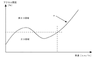
エコ判断部13は、さらに、エコ運転の表示が可能であると判定した場合には、次いで、エコ運転を判断するための判定しきい値を算出する(ステップS3)。判定しきい値の算出は、例えば、図4に示す燃費マップを参照して行われる。当該燃費マップには、車速と、その車速の時にエコ運転であるか否かを判断するためのアクセル開度の判定しきい値との関係が記録されている。当該燃費マップ上の曲線aは、エコ領域と非エコ領域とを分ける境界線であって、境界線上の値がその車速における判定しきい値を示す。エコ判断部13は、このような燃費マップを保持しており、各種センサ50で測定された車速からアクセル開度の判定しきい値を算出する。
If it is determined that the eco driving can be displayed, the eco determination unit 13 then calculates a determination threshold value for determining the eco driving (step S3). For example, the determination threshold value is calculated with reference to a fuel consumption map shown in FIG. In the fuel consumption map, the relationship between the vehicle speed and a determination threshold value of the accelerator opening for determining whether or not the eco-driving is performed at the vehicle speed is recorded. A curve a on the fuel consumption map is a boundary line that separates the eco region and the non-eco region, and a value on the boundary line indicates a determination threshold value at the vehicle speed. The eco determination unit 13 holds such a fuel consumption map, and calculates a determination threshold value of the accelerator opening from the vehicle speed measured by the
エコ判断部13は、次いで、ステップS3の処理で算出された判定しきい値と、各種センサ50の測定データ等から求めた現在のアクセル開度と、からエコ運転状態量を算出するとともに、その算出値からエコランプの表示態様、例えば点灯又は消灯、点滅等を決定する(ステップS4)。このエコ運転状態量は、
エコ運転状態量=((現在のアクセル開度)/判定しきい値)×100
により算出できる。また、エコランプの点灯等については、例えば、エコ運転状態量が100%以下であれば、エコ運転状態であると判定し、エコランプを点灯する決定をし、逆に、エコ運転状態量が100%より大きければ、非エコ運転状態であると判定し、エコランプを消灯する決定をする。
Next, the eco judgment unit 13 calculates the eco driving state amount from the judgment threshold value calculated in the process of step S3 and the current accelerator opening obtained from the measurement data of the
Eco-drive state quantity = ((current accelerator opening) / judgment threshold) x 100
Can be calculated. As for the lighting of the eco lamp, for example, if the eco driving state amount is 100% or less, it is determined that the eco driving state is in effect and the eco lamp is turned on, and conversely, the eco driving state amount is 100%. If it is larger, it is determined that the vehicle is in the non-eco driving state, and the eco lamp is turned off.
エコ判断部13は、次いで、ガード処理を実施する(ステップS5)。ガード処理とは、エコランプの表示と、エコバーの表示とにずれが生じないようにするための処理である。 Next, the eco judgment unit 13 performs a guard process (step S5). The guard process is a process for preventing a deviation between the display of the eco lamp and the display of the eco bar.
ここで、ガード処理について図5及び図6を参照して簡単に説明する。
エコ判断部13は、図5に示すように、判定しきい値に所定値を加算してガード用しきい値を算出する。エコ運転状態量が上昇しているときには、エコ運転状態量がガード用しきい値を超えてからの所定時間をガード時間とする。また、エコ運転状態量が降下しているときには、エコ運転状態量が上限しきい値を下回ってからの所定時間をガード時間とする。
Here, the guard process will be briefly described with reference to FIGS.
As shown in FIG. 5, the eco determination unit 13 adds a predetermined value to the determination threshold value to calculate a guard threshold value. When the eco-driving state quantity is increasing, a predetermined time after the eco-driving state quantity exceeds the guard threshold is defined as a guard time. Further, when the eco-driving state quantity is decreasing, a predetermined time after the eco-driving state quantity falls below the upper limit threshold is set as the guard time.
このガード時間内では、エコ運転状態量に変動が生じないようにエコ運転状態量を変更する。すなわち、ガード時間の間はエコ運転状態量を100%維持する。これにより、図6に示すようなガード処理後のエコ運転状態量を得ることができる。 Within this guard time, the eco-driving state quantity is changed so that the eco-driving state quantity does not change. That is, the eco-driving state amount is maintained 100% during the guard time. Thereby, the eco-drive state quantity after the guard process as shown in FIG. 6 can be obtained.
エコ判断部13は、次いで、なまし処理を実施する(ステップS6)。エコ運転状態量がノイズ等によって一時的に変化したり、エコ運転状態量が急激に変化したりするのを抑制するために、以下に示す式に従ってなまし処理を実施する。
P(n)=(1−D)P(n−1)+D×P
なお、Pはエコ運転状態量を表し、P(n)はエコ運転状態量のなまし処理された今回の値、P(n−1)はエコ運転状態量の前回の値である。また、Dはなまし定数である。
この他に、各種センサ2から測定データを入力するごとに生成されるエコ運転状態量を所定回分加算して平均を求めた移動平均や、レートリミット、出力値フィルタ(ローパスフィルタ)処理のような処理を行ってもよい。
Next, the eco judgment unit 13 performs an annealing process (step S6). In order to prevent the eco-driving state quantity from temporarily changing due to noise or the like, or the eco-driving state quantity from changing suddenly, a smoothing process is performed according to the following equation.
P (n) = (1-D) P (n-1) + D * P
Note that P represents an eco-driving state quantity, P (n) is the current value after the eco-driving state quantity is smoothed, and P (n-1) is the previous value of the eco-driving state quantity. D is an annealing constant.
In addition to this, a moving average obtained by adding a predetermined number of eco-driving state quantities generated each time measurement data is input from
エコ判断部13は、次いで、なまし処理を施したエコ運転状態量と、エコランプの表示状態との不整合を取り除く処理を行う(ステップS7)。すなわち、図7に示すように、なまし処理後のエコ運転状態量が100%となるタイミングに合わせて、エコランプの点灯と消灯とを切替える。 Next, the eco judgment unit 13 performs a process of removing the mismatch between the eco driving state quantity subjected to the annealing process and the display state of the eco lamp (step S7). That is, as shown in FIG. 7, the eco lamp is switched on and off in accordance with the timing at which the eco operation state amount after the annealing process becomes 100%.
エコ判断部13は、次いで、車両が現在停車状態にあるか否かを判定する(ステップS8)。当該処理は、各種センサ50から入力された車速に基づいて、車両が停車状態にあるか否かによって行われる。例えば、車速が2km/hを下回った場合には、車両が停車状態にあると判定し、車速が4km/hを上回った場合には、車両が走行状態にあると判定する。また、車速が2km/hと4km/hとの間にある場合には、停車判定をただちに行わずに、その後、車速の変化があるまで待機する。
Next, the eco judgment unit 13 determines whether or not the vehicle is currently stopped (step S8). The process is performed based on whether or not the vehicle is stopped based on the vehicle speed input from the
エコ判断部13は、ここで、車両が停止状態でないと判定した場合、例えば走行状態であると判定した場合には、算出したエコ運転状態量と、エコランプの表示状態を示す情報とをエコ状態信号としてメーターECU20に通知し(ステップS9)、処理を終了する。
Here, when the eco determination unit 13 determines that the vehicle is not in a stopped state, for example, when it is determined that the vehicle is in a traveling state, the eco state is calculated by using the calculated eco driving state amount and information indicating the display state of the eco lamp. The
尚、上述したステップS1の処理において、エコ判断部13が、入力された測定データが正常でないと判定した場合には、各種センサ50のフェール時のエコ運転状態量として0%を算出する(ステップS10)。また、ステップS2の処理において、エコ判断部13が、エコ運転表示が可能な状態ではないと判定した場合には、除外時のエコ運転状態量として0%を算出する(ステップS11)。さらに、ステップ8の処理において、車両が停止状態であると判定した場合には、車両停止時のエコ運転状態量として0%を算出する(ステップS12)。
In the process of step S1 described above, when the eco determination unit 13 determines that the input measurement data is not normal, 0% is calculated as the eco driving state amount at the time of failure of the various sensors 50 (step S1). S10). In the process of step S2, when the eco determination unit 13 determines that the eco driving display is not possible, 0% is calculated as the eco driving state amount at the time of exclusion (step S11). Furthermore, if it is determined in
次に、メーターECU20内の通知制御部21の処理手順について図8及び図9を参照して説明する。
図8は通知制御部21の処理手順の一例を示すフローチャート、図9はエコ表示部41の表示例である。
Next, the processing procedure of the
FIG. 8 is a flowchart illustrating an example of a processing procedure of the
通知制御部21は、図8に示すように、パワートレインECU10からエコ状態信号を受信するまで待機状態を続け(ステップS21)、エコ状態信号を受信したと判定した場合には、当該エコ状態信号に基づき、インジケータパネル40のエコ表示部41の表示を制御する(ステップS22)。エコ表示部41の表示の制御には、例えば、エコランプの点灯やエコバーの表示等がある。
As shown in FIG. 8, the
このように、エコ運転支援システムは、パワートレインECU10及びメーターECU20の各機能により、インジケータパネル40にエコ運転状態量をエコバーとして表示し、また、エコランプを点灯等する。
As described above, the eco-driving support system displays the eco-driving state quantity as the eco bar on the
例えば、図9(a)に示すように、エコ運転である場合には、0%から100%の間のエコ運転領域41aにエコバーが表示され、エコバーが100%に達するまでは操作余量として示される。この場合には、エコランプ41dが点灯する。 For example, as shown in FIG. 9A, in the case of eco driving, an eco bar is displayed in the eco driving area 41a between 0% and 100%, and as an operation surplus amount until the eco bar reaches 100%. Indicated. In this case, the eco lamp 41d is turned on.
一方、同図(b)に示すように、非エコ運転である場合には、100%を超える非エコ運転領域41bにまでエコバーが表示され、100%超過分は操作逸脱量として示される。この場合には、エコランプ41dが消灯する。 On the other hand, as shown in FIG. 5B, in the case of non-eco-driving, an eco-bar is displayed up to the non-eco-driving region 41b exceeding 100%, and an excess of 100% is indicated as an operation deviation amount. In this case, the eco lamp 41d is turned off.
この基準となる100%はエコ運転領域の判定しきい値を示している。これにより、ドライバーはエコ運転を視覚により認識することができる。尚、エコバーが上限しきい値100%からプラスマイナス5%未満の範囲にある場合に、エコランプ41dを点滅させるようにしてもよい。これにより、ドライバーに対しエコ運転に対する注意喚起となる。
The
次に、上述したステップS3の処理における判定しきい値の算出形態について図10から図12等を参照して説明する。
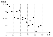
図10は判定しきい値算出処理の一例を示すフローチャート、図11は各速度域における加速度分布図、図12は各速度域に含まれる加速度を示す表である。
Next, the calculation form of the determination threshold value in the process of step S3 described above will be described with reference to FIGS.
FIG. 10 is a flowchart showing an example of the determination threshold value calculation process, FIG. 11 is an acceleration distribution diagram in each speed range, and FIG. 12 is a table showing acceleration included in each speed range.
エコ判断部13は、図10に示すように、まず、入力情報を受け付ける(ステップS31)。入力情報の受付は、例えば、エコ運転支援システムに対するスイッチを入れること等によって行われる。これにより、以後の走行状態等が燃費の学習用として記憶されていく。 As shown in FIG. 10, the eco judgment unit 13 first receives input information (step S31). The input information is received, for example, by turning on the eco-driving support system. As a result, subsequent driving conditions and the like are stored for fuel consumption learning.
エコ判断部13は、次いで、速度域判定を行う(ステップS32)。速度域判定とは、所定の速度域(例えば120km/h)を分割して走行中にある車両の車速が現在何km/hの領域にあるか否かを判定する。そして、分割によって生成された各速度域における加速度を抽出していき(ステップS33)、速度域別の加速度を記憶していく(ステップS34)。尚、速度域の分割は5分割、10分割等、任意に設定できる。 Next, the eco determination unit 13 performs speed range determination (step S32). In the speed range determination, a predetermined speed range (for example, 120 km / h) is divided to determine how many km / h the vehicle speed of the vehicle currently traveling is currently in. Then, the acceleration in each speed range generated by the division is extracted (step S33), and the acceleration for each speed range is stored (step S34). Note that the division of the speed range can be arbitrarily set such as 5 divisions and 10 divisions.
上述したステップS32〜S34の処理について図11及び図12を参照して具体的に説明する。図11に示す加速度分布図は、X軸方向を車両の速度(km/h)、Y軸方向を車両の加速度(km/h2)として表した図である。例えば、0〜23km/hの領域においては、同図に示すように、11km/h2、12km/h2、14km/h2、16km/h2の加速度が分布している。したがって、図12に示すように、0〜23km/hの領域においては、これらの加速度が記憶されていく。尚、他の速度域についても同様の手法により加速度が記憶されていく。 The processing of steps S32 to S34 described above will be specifically described with reference to FIGS. The acceleration distribution diagram shown in FIG. 11 is a diagram in which the X-axis direction is represented as the vehicle speed (km / h) and the Y-axis direction is represented as the vehicle acceleration (km / h 2 ). For example, in the region of 0 to 23 km / h, as shown in the figure, accelerations of 11 km / h 2 , 12 km / h 2 , 14 km / h 2 , and 16 km / h 2 are distributed. Therefore, as shown in FIG. 12, these accelerations are stored in the region of 0 to 23 km / h. In addition, acceleration is memorize | stored by the same method also about another speed range.
エコ判断部13は、次いで、分析期間判定を行う(ステップS35)。分析期間判定は、例えば、エコ運転支援システムのスイッチが入ってから所定の時間(例えば5時間)を経過しているか否かによって行われる。ここで、エコ判断部13は、まだ所定の時間を経過していないと判断した場合には、ドライバーの運転特性を分析中であるとして、上述したステップS32〜S34の処理を繰り返し、各速度域における加速度を記憶していく。 Next, the eco judgment unit 13 performs analysis period determination (step S35). The analysis period determination is performed based on, for example, whether or not a predetermined time (for example, 5 hours) has elapsed since the switch of the eco-driving support system was turned on. Here, when it is determined that the predetermined time has not yet elapsed, the eco determination unit 13 determines that the driving characteristics of the driver are being analyzed, and repeats the processing of steps S32 to S34 described above to determine each speed range. The acceleration at is memorized.
一方、エコ判断部13は、所定の時間が経過した場合には、分析期間が経過したと判断し、分析を止め、各速度域における加速度に対し平均化処理を行う(ステップS36)。平均化処理は、相加平均、相乗平均や調和平均等、種々の数学的・統計的手法を用いることができるが、処理の複雑さを回避するためにも相加平均であることが望ましい。必要に応じて、その加速度を記録した際の速度を重み付けに用いてもよい。また、平均化処理を行う際、平均値を求める際の各対象値のうち、最大値と最小値を除去してから処理を行うようにしてもよい。 On the other hand, when the predetermined time has elapsed, the eco determination unit 13 determines that the analysis period has elapsed, stops the analysis, and performs an averaging process on the acceleration in each speed range (step S36). As the averaging process, various mathematical / statistical methods such as an arithmetic average, a geometric average, and a harmonic average can be used. In order to avoid processing complexity, it is desirable to use an arithmetic average. If necessary, the speed when the acceleration is recorded may be used for weighting. Further, when performing the averaging process, the processing may be performed after removing the maximum value and the minimum value from the respective target values for obtaining the average value.
エコ判断部13は、次いで、補間処理を行う(ステップS37)。補間処理は、ステップS35の処理において平均化された加速度間を補間するための処理である。 Next, the eco judgment unit 13 performs an interpolation process (step S37). The interpolation process is a process for interpolating between the accelerations averaged in the process of step S35.
この補間処理について図13を参照して具体的に説明する。図13は補間処理の一例を示すグラフである。同図に示すグラフは、X軸方向を車両の速度、Y軸方向を車両の加速度として表したグラフである。各速度域における加速度は、その速度域の平均値における加速度の平均値を示している。補間処理は、例えば、各平均速度における平均加速度を直線(線分)で結ぶことによって行われる。これにより、各速度間の加速度についてもエコ運転/非エコ運転の判断が可能となる。尚、図14は図13に示すグラフをスプライン補間したグラフである。このように、スプライン補間を施すことにより、グラフは滑らかとなり、エコ運転/非エコ運転の唐突な判断が抑制される。尚、補間手法は既知の数学的手法を使用できる。 This interpolation processing will be specifically described with reference to FIG. FIG. 13 is a graph showing an example of interpolation processing. The graph shown in the figure is a graph in which the X-axis direction is the vehicle speed and the Y-axis direction is the vehicle acceleration. The acceleration in each speed range indicates the average value of the acceleration in the average value of the speed range. The interpolation process is performed, for example, by connecting the average acceleration at each average speed with a straight line (line segment). As a result, it is possible to determine eco-driving / non-eco-driving for the acceleration between the speeds. FIG. 14 is a graph obtained by performing spline interpolation on the graph shown in FIG. In this way, by performing spline interpolation, the graph becomes smooth, and abrupt judgment of eco / non-eco operation is suppressed. As the interpolation method, a known mathematical method can be used.
エコ判断部13は、次いで、ステップS37の処理によって生成されたグラフに基づき、燃費マップを生成する(ステップS38)。燃費マップの生成は、要求トルクマップ等を用い、上述したグラフをアクセル開度や車両パワーに変換して行われる。このように生成された燃費マップは、例えば図4に示したような燃費マップとなる。そして、このステップで生成された燃費マップは、ドライバーの熟練度等の運転特性が反映された初期の燃費マップとなる。以下の説明において、当該燃費マップを調教用燃費マップという。 Next, the eco judgment unit 13 generates a fuel consumption map based on the graph generated by the process of step S37 (step S38). The fuel consumption map is generated by using the required torque map or the like and converting the graph described above into the accelerator opening or the vehicle power. The fuel consumption map generated in this way is, for example, a fuel consumption map as shown in FIG. The fuel consumption map generated in this step is an initial fuel consumption map that reflects driving characteristics such as the skill level of the driver. In the following description, the fuel consumption map is referred to as a training fuel consumption map.
エコ判断部13は、次いで、自身が保持する正規の燃費マップ(デフォルト燃費マップという。)に基づいて、デフォルト燃費マップと、調教用燃費マップとの乖離量を算出する(ステップS39)。尚、デフォルト燃費マップは、製造者が製品の出荷時に提供する、エコ運転を判断するための最適な燃費マップである。 Next, the eco judgment unit 13 calculates a deviation amount between the default fuel consumption map and the training fuel consumption map based on a regular fuel consumption map (referred to as a default fuel consumption map) held by itself (step S39). The default fuel consumption map is an optimal fuel consumption map provided by the manufacturer at the time of product shipment to judge eco-driving.
エコ判断部13は、次いで、上述した乖離量を所定の分割割合(例えば5分割)により分割し、分割結果を調教用燃費マップの更新ステップとして設定する(ステップS40)。この更新ステップは、調教用燃費マップをデフォルト燃費マップに近づける際の刻みとなるパラメーターである。このように、ステップS31からS40の処理によって、ドライバーの運転特性が判断され、その判断に応じた調教用燃費マップが設定され、また、調教用燃費マップを正規の燃費マップに近づけるための刻みとなる更新ステップが設定される。 Next, the eco judgment unit 13 divides the above-described divergence amount by a predetermined division ratio (for example, 5 divisions), and sets the division result as a training fuel consumption map update step (step S40). This update step is a parameter that becomes a step when bringing the training fuel consumption map closer to the default fuel consumption map. As described above, the driving characteristics of the driver are determined by the processing of steps S31 to S40, a training fuel consumption map is set according to the determination, and the training fuel map is made to be closer to the regular fuel consumption map. An update step is set.
エコ判断部13は、調教用燃費マップや更新ステップが設定されると、走行中に更新タイミングに到達したか否かを判断する(ステップS41)。この更新タイミングは、例えば、車両の走行距離、走行時間、ドライバーのエコ運転に関する熟練度等によって判断される。 When the training fuel consumption map and the update step are set, the eco determination unit 13 determines whether or not the update timing has been reached during traveling (step S41). This update timing is determined based on, for example, the travel distance of the vehicle, the travel time, the skill level of the driver on eco driving, and the like.
例えば走行距離や走行時間によって更新タイミングを判断する場合には、上述した調教用燃費マップ等の設定がされてから走行した距離や時間を計測し、所定の距離や時間を越えたと判断した場合に、調教用燃費マップを更新ステップに基づいてデフォルト燃費マップに向けて変更していく。 For example, when the update timing is determined based on the travel distance or travel time, the distance traveled and the time traveled after the setting of the fuel consumption map for training described above is measured, and it is determined that the predetermined distance or time has been exceeded. The training fuel consumption map is changed to the default fuel consumption map based on the update step.
また、エコ運転率によって更新タイミングを判断する場合には、車両が走行している際に、調教用燃費マップ等の設定がされてからの走行時間のうち、エコ運転となった時間を計測していき、その割合が所定の割合(例えば70%)を越えたと判断した場合に、調教用マップを更新ステップに基づいてデフォルトマップに近づけるようにする。エコ運転率による更新タイミングの判断は、走行距離によって行ってもよい。 In addition, when judging the update timing based on the eco-driving rate, when the vehicle is traveling, the time when the vehicle has been eco-driving is measured out of the traveling time since the setting of the fuel consumption map for training, etc. Then, when it is determined that the ratio exceeds a predetermined ratio (for example, 70%), the training map is brought closer to the default map based on the update step. The determination of the update timing based on the eco-driving rate may be performed based on the travel distance.
さらに、ドライバーの熟練度等の運転特性によって更新タイミングを判断する場合には、ドライバーを初心者、中級者、上級者等に分け、ドライバーが初心者から中級者に変更された場合に、調教用燃費マップを更新ステップに基づいてデフォルト燃費マップに近づけるようにする。尚、ドライバーの運転特性を評価する場合には、特許文献6に記載の評価手段等を用いてもよい。エコ運転に関する熟練度は、エコ状態であると判定される頻度に基づいて判断するようにしてもよい。
Furthermore, when judging the update timing based on driving characteristics such as the driver's skill level, the driver is divided into beginners, intermediates, advanced, etc., and when the driver is changed from beginners to intermediates, the fuel consumption map for training Is made closer to the default fuel consumption map based on the update step. When evaluating the driving characteristics of the driver, the evaluation means described in
このように、エコ運転の意識や技術等が低いドライバーであっても、走行当初のうちは、ドライバーの運転特性に応じた調教用燃費マップがエコ運転支援システムに設定される。したがって、例えば、エコ運転である旨が出力されない状態からエコ運転である旨とない旨とが交互に出力されたり、エコ運転である旨の頻度が上がったりする可能性がある。これにより、ドライバーは、自身の運転がエコ運転であると認識でき、前者の煩わしさから解放され易くなる。 As described above, even if the driver has low eco-consciousness, skill, etc., the training fuel consumption map corresponding to the driving characteristics of the driver is set in the eco-driving support system at the beginning of driving. Therefore, for example, there is a possibility that the state of eco-driving is not output from the state where eco-driving is not output, and that the frequency of eco-driving is increased. As a result, the driver can recognize that his / her driving is eco-friendly, and is easily relieved from the troublesomeness of the former.
また、このような状態において、エコ運転の意識や技術等が上がると、エコ運転である旨が出力され続けるようになる。エコ運転支援システムは、ドライバーのエコ運転の意識や熟練度等が上がったと判断した場合には、図16に示すように、判定用しきい値aを更新ステップに基づいて段階的にデフォルト燃費マップ(判定しきい値)bに向けて徐々に変更していく。図15に示すように、一度に近づける場合に比べて、ドライバーのエコ運転の度合いを細かく設定できる。最終的に、調教用燃費マップaをデフォルト燃費マップbに重ねてもよい。これにより、走行当初のエコ運転より厳しいエコ運転の判断がなされ、ドライバーは、エコ運転をさらに行おうとする意識が働く可能性が高い。 Further, in such a state, when the awareness, technology, etc. of eco-driving increase, the fact that it is eco-driving continues to be output. When the eco-driving support system determines that the driver's awareness of eco-driving, skill level, etc. has increased, as shown in FIG. 16, the default fuel consumption map is gradually set based on the update threshold a for determination. (Determination threshold) Gradually change toward b. As shown in FIG. 15, the degree of eco-driving of the driver can be set more finely than when approaching at once. Finally, the training fuel consumption map a may be superimposed on the default fuel consumption map b. As a result, the judgment of eco-driving which is stricter than the initial eco-driving is made, and the driver is likely to be conscious of further eco-driving.
尚、上述した第1実施形態では、エコ判断部13をパワートレインECU10内に構成したが、図17に示すように、メーターECU20に構成するようにしてもよい。ドライバーのエコ運転の技術をレベル別に車室内の表示装置などに表示させたり、音声により出力させたりするようにしてもよい。
In the first embodiment described above, the eco judgment unit 13 is configured in the
また、ナビゲーション装置(いわゆるカーナビ)の制御を行うナビ用のECUに、上述したエコ判断部13の機能を設け、ナビゲーション装置のディスプレイ上に上述したエコバー表示を表示させることもできる。エコ判断部13をドライブレコーダー用のECUに設けるようにしてもよい。 In addition, the navigation ECU that controls the navigation device (so-called car navigation) can be provided with the function of the eco-determining unit 13 described above to display the eco-bar display described above on the display of the navigation device. The eco judgment unit 13 may be provided in the drive recorder ECU.
(第2実施形態)
上述した第1実施形態は、エンジンのみを搭載した車両にエコ運転支援情報を表示させるシステム構成について説明した。本実施形態は、エンジンとモータとを搭載したハイブリッド車両(以下、ハイブリッドをHVと略記する)に搭載されるエコ運転支援システムについて説明する。
(Second Embodiment)
1st Embodiment mentioned above demonstrated the system structure which displays eco-driving assistance information on the vehicle carrying only an engine. In the present embodiment, an eco-driving support system mounted on a hybrid vehicle (hereinafter, a hybrid is abbreviated as HV) mounted with an engine and a motor will be described.
図18には、上述したエコ判断部13と同様の構成となるエコ判断部72を、HV−ECU70に設けたエコ運転支援システムの構成を示す。
HV−ECU70は、不図示のバッテリECU、エンジンECUや、モータ・ジェネレータECU80等を相互に管理制御して、ハイブリッド車両が最も効率よく運行できるようにハイブリッドシステムの全体を制御する。
FIG. 18 shows a configuration of an eco driving support system in which an HV-
The HV-
HV−ECU70には、図18に示すようにHV制御部71と、エコ判断部72とが設けられている。
HV制御部71は、各種センサ50によって測定されたセンサ信号や、他のEUCからの信号を入力して、ハイブリッドシステムを制御する制御信号を生成する。また、HV制御部71は、エコ判断部72にHVシステムの状態を示すHV状態信号を出力する。このHV状態信号には、車両パワー、車両の限界出力パワー、バッテリの充電許可電力などが含まれる。
The HV-
The
エコ判断部72は、HV制御部71から出力されるHV状態信号と、各種センサ50から出力されるセンサ信号とを入力して、エコ運転の状態を表すエコ運転状態量を算出する。
The
ここで、エコ判断部72で生成されるエコ運転状態量について説明する。
本実施形態で生成されるエコ運転状態量は、車両パワーに基づいて算出される。車両パワーは、電力量や仕事率と表現され、エンジンのトルクとエンジン回転数との積と、モータのトルクとモータの回転数との積との和で求めることができる。
ハイブリッド車両においては、電力で駆動されるモータと、エンジンとが設けられているので、モータとエンジンの双方で発生するエネルギーを1つの基準で表すために車両パワーを用いている。
Here, the eco-driving state quantity generated by the
The eco-driving state quantity generated in the present embodiment is calculated based on the vehicle power. The vehicle power is expressed as the amount of electric power and the power, and can be obtained by the sum of the product of the engine torque and the engine speed and the product of the motor torque and the motor speed.
In a hybrid vehicle, since a motor driven by electric power and an engine are provided, vehicle power is used to express energy generated by both the motor and the engine by one reference.
エコ判断部72は、各種センサ50から車速を取得すると共に、HV制御部71から車両の現在の車両パワーを取得する。次に、図19に示す燃費マップを参照して、現在の車速でエコ運転状態と判定できる車両パワーの判定しきい値aを算出する。
The
燃費マップには、車速と、エコ運転状態であると判定できる車両パワーの上限値(判定しきい値)が示されている。図19に示す燃費マップを参照して車両パワーの判定しきい値を求めると、エコ判断部72は、以下の式に従ってHV制御部71から取得した現在の車両パワーを判定しきい値で除算し、除算した値に100を積算して、エコ運転状態量を算出する。
エコ運転状態量=((現在の車両パワー/判定しきい値)×100)(%)
The fuel efficiency map shows the vehicle speed and the upper limit value (determination threshold) of vehicle power that can be determined to be in the eco-driving state. When the vehicle power determination threshold value is obtained with reference to the fuel consumption map shown in FIG. 19, the
Eco-drive state quantity = ((current vehicle power / judgment threshold) x 100) (%)
図20には、インジケータパネル40のエコ表示部41に表示される表示例を示す。
本実施形態では、図20に示すように車両が回生運転状態にあると判定できる回生運転領域41cと、HVエコゾーン41eの表示とをさらに追加表示している。
FIG. 20 shows a display example displayed on the
In the present embodiment, as shown in FIG. 20, a regenerative operation area 41c where the vehicle can be determined to be in a regenerative operation state and a display of the HV eco zone 41e are additionally displayed.
図20に示す回生運転領域41cは、ハイブリッド車両用に用意された領域であり、回生ブレーキの操作によって車両の運転状態が回生状態にあることを示している。
また、HVエコゾーン41eは、エコ運転状態量がHVエコゾーン41e内にあれば、車両がモータだけで駆動されていることを示している。
A regenerative operation area 41c shown in FIG. 20 is an area prepared for a hybrid vehicle, and indicates that the driving state of the vehicle is in a regenerative state by operating a regenerative brake.
The HV eco-zone 41e indicates that the vehicle is driven only by the motor if the eco-drive state quantity is within the HV eco-zone 41e.
本実施形態においても、車両のエコ運転度合いを示すエコ運転状態量が判るので、エコ運転のための操作の指針を提供することができる。すなわち、エコ運転をするために、どの程度運転操作を改善すればよいのか、又はエコ運転状態でいるために、あとどの程度アクセルを踏み込んでもよいのかを示すことができる。 Also in this embodiment, since the eco-driving state quantity indicating the eco-driving degree of the vehicle is known, it is possible to provide an operation guideline for eco-driving. That is, it is possible to indicate how much the driving operation should be improved in order to perform eco-driving, or how much the accelerator can be further depressed in order to be in the eco-driving state.
以上、本発明の好ましい実施形態について詳述したが、本発明に係る特定の実施形態に限定されるものではなく、特許請求の範囲に記載された本発明の要旨の範囲内において、種々の変形・変更が可能である。例えば、本発明のプログラムを通信手段により提供することはもちろん、CD−ROM等の記録媒体に格納して提供することも可能である。 The preferred embodiments of the present invention have been described in detail above, but the present invention is not limited to the specific embodiments according to the present invention, and various modifications are possible within the scope of the gist of the present invention described in the claims.・ Change is possible. For example, the program of the present invention can be provided not only by communication means but also stored in a recording medium such as a CD-ROM.
例えば、エンジンのみを搭載した車両、ハイブリッド車両ともにエコ表示部13にエコランプ41dは設けても、設けなくてもよい。
また、エンジンのみを搭載した車両、ハイブリッド車両ともに非エコ運転領域41bの表示をエコバー表示ではなく、LED等のオン/オフ点灯制御で表示させてもよい(図21(a)参照)。エコ運転状態量が100%を超えると、非エコ運転領域41bをオン(点灯)させる。
For example, the eco lamp 41d may or may not be provided in the eco display unit 13 for both a vehicle equipped with only an engine and a hybrid vehicle.
In addition, the display of the non-eco-operation area 41b may be displayed by on / off lighting control such as an LED instead of the eco-bar display in both the vehicle equipped with only the engine and the hybrid vehicle (see FIG. 21A). When the amount of eco-drive state exceeds 100%, the non-eco-drive region 41b is turned on (lighted).
また、ハイブリッド車両のエコ表示部31において、回生運転領域41cの表示をエコバー表示にしてもよいし、LEDのオン/オフ点灯制御を行ってもよい。
また、図21(b)に示す例は、ハイブリッド車両用のエコバー表示であるが、回生運転領域41cの他に、回生ブレーキ以外の電力の回収ができないブレーキが作動された領域41fとを表示させてもよい。
Further, in the eco display unit 31 of the hybrid vehicle, the display of the regenerative operation area 41c may be an eco bar display, or LED on / off lighting control may be performed.
The example shown in FIG. 21B is an eco bar display for a hybrid vehicle. In addition to the regenerative operation area 41c, an area 41f in which a brake other than the regenerative brake that cannot collect power is activated is displayed. May be.
また、ハイブリッド車両のエコ表示部72において、エコ運転状態量が0%以上の領域を、HVエコゾーン41dの領域と、それ以外の領域とに分割してもよいし、HVエコゾーン41dを設けない構成であってもよい。
Further, in the
また、エンジンのみを搭載した車両とハイブリッド車両とのエコ表示部13,72において、エコバー表示ではなく、図21(c)に示すスピードメータのような円表示を採用してもよい。
Further, in the
また、上述した実施形態では、車速等に基づいて車両のエコ運転状態量を求めて、リアルタイムにこれを表示しているが、例えば、エコ判断部で求めた車速とエコ運転状態量を記録媒体等に記録しておき、降車後にコンピュータ装置に記録媒体の記録内容を読み込んで、エコ運転状態量の経時的な変化を表示させるようにしてもよい。 In the above-described embodiment, the eco-driving state quantity of the vehicle is obtained based on the vehicle speed or the like and displayed in real time. For example, the vehicle speed and the eco-driving state quantity obtained by the eco judgment unit are recorded on the recording medium. For example, the recorded contents of the recording medium may be read into the computer device after getting off and the change in the eco-driving state amount with time may be displayed.
また、図1,17,18に示したようにエコ判断部13,72から表示制御を行う車載ECU(メーターECU、ナビECU等)を介してエコ表示を行うように構成してもよいし、エコ判断部13,72で直接、エコ表示部41の表示制御を行うようにしてもよい。
In addition, as shown in FIGS. 1, 17, and 18, eco-display may be performed via an in-vehicle ECU (meter ECU, navigation ECU, etc.) that performs display control from the
また、上述した実施形態では、調教用燃費マップを生成し、走行距離等が所定の条件に到達した場合に、決定された更新ステップに基づいて調教用マップを切り替えていくようにしたが、更新ステップに応じたすべての調教用マップを更新ステップ決定後に生成しておき、走行距離等が所定の条件に到達した場合に、調教用燃費マップを切り替えるようにしてもよい。 In the above-described embodiment, the training fuel consumption map is generated, and when the travel distance or the like reaches a predetermined condition, the training map is switched based on the determined update step. All the training maps corresponding to the steps may be generated after the update step is determined, and the training fuel consumption map may be switched when the travel distance or the like reaches a predetermined condition.
10 パワートレインECU
11 エンジン制御部
12 トランスミッション制御部
13 エコ判断部
20 メーターECU
21 通知制御部
30 ネットワーク
40 インジケータパネル
41 エコ表示部
41a エコ運転領域
41b 非エコ運転領域
41c 回生運転領域
41d エコランプ
41e HVエコゾーン
50 センサ
60 アクチュエータ
70 HV−ECU
71 HV制御部
72 エコ判断部
80 モータ・ジェネレータECU
10 Powertrain ECU
11
DESCRIPTION OF
71
Claims (4)
前記エコ状態判定手段の判定結果に基づいて、車両の運転状態のエコ度合いを報知するように制御する報知制御手段と、
前記判定しきい値を、初期の判定しきい値からエコ状態であると判定されにくい判定しきい値に、徐々に変化させる判定しきい値変更手段と、を有することを特徴とするエコ運転支援装置。 Eco state determination means for determining whether or not the driving state of the vehicle is in an eco state based on a determination threshold;
Based on the determination result of the eco state determination unit, a notification control unit that controls to notify the eco degree of the driving state of the vehicle;
An eco-driving support comprising: a judgment threshold value changing means for gradually changing the judgment threshold value from an initial judgment threshold value to a judgment threshold value that is difficult to judge as being in an eco state apparatus.
The eco-driving support apparatus according to claim 3, wherein the skill level of the driver regarding eco-driving is determined based on a frequency at which the eco-state determining unit determines that the driver is in an eco-state.
Priority Applications (1)
| Application Number | Priority Date | Filing Date | Title |
|---|---|---|---|
| JP2007334214A JP2009156132A (en) | 2007-12-26 | 2007-12-26 | Eco drive assist device |
Applications Claiming Priority (1)
| Application Number | Priority Date | Filing Date | Title |
|---|---|---|---|
| JP2007334214A JP2009156132A (en) | 2007-12-26 | 2007-12-26 | Eco drive assist device |
Publications (2)
| Publication Number | Publication Date |
|---|---|
| JP2009156132A true JP2009156132A (en) | 2009-07-16 |
| JP2009156132A5 JP2009156132A5 (en) | 2011-09-01 |
Family
ID=40960409
Family Applications (1)
| Application Number | Title | Priority Date | Filing Date |
|---|---|---|---|
| JP2007334214A Pending JP2009156132A (en) | 2007-12-26 | 2007-12-26 | Eco drive assist device |
Country Status (1)
| Country | Link |
|---|---|
| JP (1) | JP2009156132A (en) |
Cited By (4)
| Publication number | Priority date | Publication date | Assignee | Title |
|---|---|---|---|---|
| JP2010041750A (en) * | 2008-07-31 | 2010-02-18 | Fujitsu Ten Ltd | Fuel-saving drive diagnosis device, fuel-saving drive diagnosis system and fuel-saving drive diagnosis method |
| WO2012014638A1 (en) * | 2010-07-30 | 2012-02-02 | 日産自動車株式会社 | Vehicle driving assistance device |
| EP3018326A1 (en) | 2014-11-05 | 2016-05-11 | Yamaha Hatsudoki Kabushiki Kaisha | Straddle-type vehicle |
| JP2016205898A (en) * | 2015-04-17 | 2016-12-08 | 株式会社豊田中央研究所 | Torque vibration estimation device and torque vibration estimation program |
Citations (2)
| Publication number | Priority date | Publication date | Assignee | Title |
|---|---|---|---|---|
| JP2002362185A (en) * | 2001-06-05 | 2002-12-18 | Miyama Kk | Vehicle driving state evaluation system |
| JP2007284049A (en) * | 2007-03-31 | 2007-11-01 | Wataru Horikawa | Economical drive support device, car-navigation system, and economical drive support program |
-
2007
- 2007-12-26 JP JP2007334214A patent/JP2009156132A/en active Pending
Patent Citations (2)
| Publication number | Priority date | Publication date | Assignee | Title |
|---|---|---|---|---|
| JP2002362185A (en) * | 2001-06-05 | 2002-12-18 | Miyama Kk | Vehicle driving state evaluation system |
| JP2007284049A (en) * | 2007-03-31 | 2007-11-01 | Wataru Horikawa | Economical drive support device, car-navigation system, and economical drive support program |
Cited By (7)
| Publication number | Priority date | Publication date | Assignee | Title |
|---|---|---|---|---|
| JP2010041750A (en) * | 2008-07-31 | 2010-02-18 | Fujitsu Ten Ltd | Fuel-saving drive diagnosis device, fuel-saving drive diagnosis system and fuel-saving drive diagnosis method |
| JP4495234B2 (en) * | 2008-07-31 | 2010-06-30 | 富士通テン株式会社 | Fuel saving driving diagnosis device, fuel saving driving diagnosis system and fuel saving driving diagnosis method |
| WO2012014638A1 (en) * | 2010-07-30 | 2012-02-02 | 日産自動車株式会社 | Vehicle driving assistance device |
| JP2012030675A (en) * | 2010-07-30 | 2012-02-16 | Nissan Motor Co Ltd | Vehicle driving assistance device |
| US8878662B2 (en) | 2010-07-30 | 2014-11-04 | Nissan Motor Co., Ltd. | Vehicle driving assistance device |
| EP3018326A1 (en) | 2014-11-05 | 2016-05-11 | Yamaha Hatsudoki Kabushiki Kaisha | Straddle-type vehicle |
| JP2016205898A (en) * | 2015-04-17 | 2016-12-08 | 株式会社豊田中央研究所 | Torque vibration estimation device and torque vibration estimation program |
Similar Documents
| Publication | Publication Date | Title |
|---|---|---|
| JP5086201B2 (en) | Eco driving support device and method | |
| CN102105324B (en) | Low fuel consumption driving diagnostic device, low fuel consumption driving diagnostic system, controller for electrical drive device, low fuel consumption driving scoring device, and low fuel consumption driving diagnostic method | |
| EP3360718B1 (en) | Eco-drive assist apparatus, eco-drive assist information generating apparatus, eco-drive assist information calculation apparatus, eco-drive state display apparatus, eco-drive assist system, and eco-drive assist information calculation method | |
| US8290697B2 (en) | Haptic apparatus and coaching method for improving vehicle fuel economy | |
| US8249767B2 (en) | Eco-drive assist apparatus and method | |
| EP2320052A1 (en) | Fuel saving driving diagnostic equipment, in-vehicle system, drive control apparatus, and fuel saving driving diagnostic program | |
| US20110148618A1 (en) | Fuel-saving driving diagnostic device, fuel-saving driving diagnostic system, travel control device, fuel-saving driving rating device, and fuel-saving driving diagnostic method | |
| JP2010037953A (en) | Fuel saving operation diagnosis device, fuel saving operation diagnosis system, and fuel saving operation diagnosis method | |
| JP5296449B2 (en) | Eco driving support device | |
| US9079588B2 (en) | Method and device for outputting driving information indicating an acceleration option that is optimal in terms of power consumption in a motor vehicle | |
| JP5143540B2 (en) | Eco driving support device | |
| US20140324317A1 (en) | Display device and method for presenting vehicle variables for a motor vehicle | |
| JP2011126341A (en) | Vehicular information display device | |
| JP2009156132A (en) | Eco drive assist device | |
| JP5337501B2 (en) | Eco driving support device | |
| JP4456630B2 (en) | Eco operation status display device | |
| JP4456631B2 (en) | Eco driving support device | |
| US20110112749A1 (en) | Fuel-saving driving diagnosis apparatus, in-vehicle system, drive control apparatus, and fuel-saving driving diagnosis program | |
| JP5408920B2 (en) | Fuel saving driving diagnosis device, fuel saving driving diagnosis system, travel control device, fuel saving driving scoring device, and fuel saving driving diagnosis method | |
| WO2010013652A1 (en) | Fuel saving driving diagnostic equipment, in-vehicle system, drive control apparatus, and fuel saving driving diagnostic program | |
| JP5460896B2 (en) | Eco driving support device and method | |
| JP5010488B2 (en) | Fuel consumption appropriateness judgment system | |
| JP4376935B2 (en) | Eco driving support device | |
| JP2018030416A (en) | Vehicular control device and information provision method | |
| JP5882596B2 (en) | Environmental load display method for vehicles |
Legal Events
| Date | Code | Title | Description |
|---|---|---|---|
| A621 | Written request for application examination |
Free format text: JAPANESE INTERMEDIATE CODE: A621 Effective date: 20100625 |
|
| A521 | Request for written amendment filed |
Free format text: JAPANESE INTERMEDIATE CODE: A523 Effective date: 20110719 |
|
| A977 | Report on retrieval |
Free format text: JAPANESE INTERMEDIATE CODE: A971007 Effective date: 20110930 |
|
| A131 | Notification of reasons for refusal |
Free format text: JAPANESE INTERMEDIATE CODE: A131 Effective date: 20111004 |
|
| A711 | Notification of change in applicant |
Free format text: JAPANESE INTERMEDIATE CODE: A711 Effective date: 20111125 |
|
| A521 | Request for written amendment filed |
Free format text: JAPANESE INTERMEDIATE CODE: A523 Effective date: 20111128 |
|
| A521 | Request for written amendment filed |
Free format text: JAPANESE INTERMEDIATE CODE: A821 Effective date: 20111125 |
|
| A131 | Notification of reasons for refusal |
Free format text: JAPANESE INTERMEDIATE CODE: A131 Effective date: 20120117 |
|
| A521 | Request for written amendment filed |
Free format text: JAPANESE INTERMEDIATE CODE: A523 Effective date: 20120220 |
|
| A02 | Decision of refusal |
Free format text: JAPANESE INTERMEDIATE CODE: A02 Effective date: 20120313 |
|
| A521 | Request for written amendment filed |
Free format text: JAPANESE INTERMEDIATE CODE: A523 Effective date: 20120607 |
|
| A911 | Transfer to examiner for re-examination before appeal (zenchi) |
Free format text: JAPANESE INTERMEDIATE CODE: A911 Effective date: 20120614 |
|
| A912 | Re-examination (zenchi) completed and case transferred to appeal board |
Free format text: JAPANESE INTERMEDIATE CODE: A912 Effective date: 20120629 |