JP5460896B2 - Eco driving support device and method - Google Patents
Eco driving support device and method Download PDFInfo
- Publication number
- JP5460896B2 JP5460896B2 JP2013004648A JP2013004648A JP5460896B2 JP 5460896 B2 JP5460896 B2 JP 5460896B2 JP 2013004648 A JP2013004648 A JP 2013004648A JP 2013004648 A JP2013004648 A JP 2013004648A JP 5460896 B2 JP5460896 B2 JP 5460896B2
- Authority
- JP
- Japan
- Prior art keywords
- eco
- driving
- state
- engine
- driving state
- Prior art date
- Legal status (The legal status is an assumption and is not a legal conclusion. Google has not performed a legal analysis and makes no representation as to the accuracy of the status listed.)
- Active
Links
- 238000000034 method Methods 0.000 title claims description 17
- 230000001172 regenerating effect Effects 0.000 claims description 13
- 239000000446 fuel Substances 0.000 description 12
- 238000012545 processing Methods 0.000 description 6
- 230000008859 change Effects 0.000 description 5
- 230000008569 process Effects 0.000 description 5
- 230000008929 regeneration Effects 0.000 description 5
- 238000011069 regeneration method Methods 0.000 description 5
- 238000005259 measurement Methods 0.000 description 4
- 238000004891 communication Methods 0.000 description 3
- CURLTUGMZLYLDI-UHFFFAOYSA-N Carbon dioxide Chemical compound O=C=O CURLTUGMZLYLDI-UHFFFAOYSA-N 0.000 description 2
- 230000005540 biological transmission Effects 0.000 description 2
- 239000002803 fossil fuel Substances 0.000 description 2
- 238000010248 power generation Methods 0.000 description 2
- 125000002066 L-histidyl group Chemical group [H]N1C([H])=NC(C([H])([H])[C@](C(=O)[*])([H])N([H])[H])=C1[H] 0.000 description 1
- 230000005856 abnormality Effects 0.000 description 1
- 230000001133 acceleration Effects 0.000 description 1
- 230000006978 adaptation Effects 0.000 description 1
- 230000008901 benefit Effects 0.000 description 1
- 239000001569 carbon dioxide Substances 0.000 description 1
- 229910002092 carbon dioxide Inorganic materials 0.000 description 1
- 238000002485 combustion reaction Methods 0.000 description 1
- 230000000881 depressing effect Effects 0.000 description 1
- 238000010586 diagram Methods 0.000 description 1
- 238000005516 engineering process Methods 0.000 description 1
- 230000007613 environmental effect Effects 0.000 description 1
- 230000007717 exclusion Effects 0.000 description 1
- 230000006870 function Effects 0.000 description 1
- 238000002347 injection Methods 0.000 description 1
- 239000007924 injection Substances 0.000 description 1
- 238000012986 modification Methods 0.000 description 1
- 230000004048 modification Effects 0.000 description 1
- 239000000126 substance Substances 0.000 description 1
Images


Classifications
-
- Y—GENERAL TAGGING OF NEW TECHNOLOGICAL DEVELOPMENTS; GENERAL TAGGING OF CROSS-SECTIONAL TECHNOLOGIES SPANNING OVER SEVERAL SECTIONS OF THE IPC; TECHNICAL SUBJECTS COVERED BY FORMER USPC CROSS-REFERENCE ART COLLECTIONS [XRACs] AND DIGESTS
- Y02—TECHNOLOGIES OR APPLICATIONS FOR MITIGATION OR ADAPTATION AGAINST CLIMATE CHANGE
- Y02T—CLIMATE CHANGE MITIGATION TECHNOLOGIES RELATED TO TRANSPORTATION
- Y02T10/00—Road transport of goods or passengers
- Y02T10/80—Technologies aiming to reduce greenhouse gasses emissions common to all road transportation technologies
- Y02T10/84—Data processing systems or methods, management, administration
Landscapes
- Hybrid Electric Vehicles (AREA)
- Instrument Panels (AREA)
- Control Of Vehicle Engines Or Engines For Specific Uses (AREA)
- Combined Controls Of Internal Combustion Engines (AREA)
Description
本発明は、ドライバのエコ運転を支援する技術に関する。 The present invention relates to a technology for supporting a driver's eco-driving.
近年、環境保護の観点からドライバのエコ運転を支援するエコ運転支援装置が車両に搭載されるようになってきた。エコ運転支援装置では、例えば、アクセルの踏み込み量やエンジンとトランスミッションの効率、さらには走行速度や加速度などから燃費のよい走行状態(以下、燃費のよい走行状態のことをエコ運転状態と呼ぶ)にあるか否かを判定している。エコ運転状態にあると判定される場合には、LED(Light Emitting Diode)等を点灯させている。また、車両が走行中のある瞬間での燃料消費率を計算して、瞬間燃費として表示する技術も知られている。 In recent years, an eco-driving support device that supports a driver's eco-driving from the viewpoint of environmental protection has been mounted on vehicles. In the eco-driving support device, for example, in a driving state with good fuel consumption (hereinafter referred to as an eco-driving state), the amount of accelerator depression, the efficiency of the engine and transmission, and the driving speed and acceleration, etc. It is determined whether or not there is. When it is determined that the vehicle is in the eco-drive state, an LED (Light Emitting Diode) or the like is lit. There is also known a technique for calculating a fuel consumption rate at a certain moment while the vehicle is traveling and displaying it as an instantaneous fuel consumption.
また、特許文献1では、マークで表示される目標燃費と、バーグラフで表示される瞬間燃費とを共通の指標で示し、目標燃費に対する瞬間燃費の良否を瞬時に判断できるようにしている。
また、特許文献2では、アクセル操作量に基づいて、アクセル操作量の時間変化率を所定時間おきに算出して、変化率が規定値以下である場合にエコ表示を表示させている。
Further, in
Further, in Patent Document 2, the time change rate of the accelerator operation amount is calculated every predetermined time based on the accelerator operation amount, and the eco display is displayed when the change rate is equal to or less than a specified value.
ハイブリッド車両においては、高速走行時のエコ運転情報の表示に工夫を施さないと、ユーザの運転操作とは異なるエコ運転情報が表示され、ユーザに違和感を与えてしまう問題がある。
例えば、ハイブリッド車両においては、車両が高速走行になるとエンジンは常に始動している。つまり、走行中にユーザがアクセルペダルから足を離してもエンジンは始動状態にある。ユーザはアクセルペダルを踏んでいないのにエンジンは始動状態にあるので、エンジンが運転状態であることを表す情報が表示部に表示されてしまう。
In a hybrid vehicle, if the display of eco-driving information at high speed is not devised, eco-driving information different from the user's driving operation is displayed, which gives the user a sense of incongruity.
For example, in a hybrid vehicle, the engine is always started when the vehicle runs at a high speed. That is, the engine is in a starting state even if the user removes his / her foot from the accelerator pedal while traveling. Since the user is not stepping on the accelerator pedal but the engine is in a starting state, information indicating that the engine is in an operating state is displayed on the display unit.
本発明は上記事情に鑑みてなされたものであり、ユーザの運転操作と、表示手段に表示されるエコ運転の状態量との表示のずれを軽減することができるエコ運転支援装置及び方法を提供することを目的とする。 The present invention has been made in view of the above circumstances, and provides an eco-driving support apparatus and method that can reduce a display deviation between a user's driving operation and an eco-driving state quantity displayed on a display unit. The purpose is to do.
かかる目的を達成するために本発明のエコ運転支援装置は、エンジンとモータとを駆動源として備えるハイブリッド車両における運転状態のエコ度合いを表すエコ運転状態量を表示するエコ運転支援装置であって、車両で発生する車両パワーに基づいて前記エコ運転状態量を算出するエコ運転状態量算出手段と、前記エコ運転状態量を、前記エンジンを始動させる車両パワーを示す始動しきい値に対する相対量で図形表示させるものであり、前記エンジンが作動している状態にあるときには、前記エコ運転状態量が前記始動しきい値の境界上、もしくは前記エコ運転状態量が前記始動しきい値よりもエコ度合いが悪い側に位置するように表示を制御する表示制御手段と、を備え、前記表示制御手段は、前記エンジンは作動している状態にあるが、ユーザによる運転操作が車両パワーを要求しない操作状態にあるときには、前記エコ運転状態量を前記始動しきい値よりもエコ度合いが良い側に位置するように表示させることを特徴とする。 In order to achieve such an object, the eco-driving support device of the present invention is an eco-driving support device that displays an eco-driving state amount representing an eco-level of a driving state in a hybrid vehicle including an engine and a motor as drive sources, An eco-driving state quantity calculating means for calculating the eco-driving state quantity based on vehicle power generated in the vehicle, and the eco-driving state quantity in a figure relative to a starting threshold value indicating a vehicle power for starting the engine; When the engine is in an operating state, the eco-driving state quantity is on the boundary of the starting threshold value, or the eco-driving state quantity is more eco-friendly than the starting threshold value. Display control means for controlling the display so as to be positioned on the bad side, and the display control means is in a state where the engine is operating. When the driving operation by the user on the operation state not requiring the vehicle power is characterized by displaying the eco-drive state quantity so as to be located in the eco degree better side than the starting threshold.
本発明のエコ運転支援装置は、エンジンとモータとを駆動源として備えるハイブリッド車両における運転状態のエコ度合いを表すエコ運転状態量を表示するエコ運転支援装置であって、車両で発生する車両パワーに基づいて前記エコ運転状態量を算出するエコ運転状態量算出手段と、前記エコ運転状態量を、前記エンジンを始動させる車両パワーを示す始動しきい値に対する相対量で図形表示させるものであり、前記エンジンが作動している状態にあるときには、前記エコ運転状態量が前記始動しきい値の境界上、もしくは、前記エコ運転状態量が前記始動しきい値よりもエコ度合いが悪い側に位置するように表示を制御する表示制御手段と、を備え、前記表示制御手段は、前記始動しきい値を固定位置に表示するが、前記エンジンが作動している状態で、かつ、ユーザによる運転操作が車両パワーを要求しない操作状態にあるときには、前記エコ運転状態量を前記始動しきい値よりもエコ度合いが良い側に位置するように表示させることを特徴とする。 An eco-driving support device according to the present invention is an eco-driving support device that displays an eco-driving state quantity that represents an eco-level of a driving state in a hybrid vehicle including an engine and a motor as drive sources, and the vehicle driving power that is generated in the vehicle. and eco operation state quantity calculating means for calculating the eco operation state quantity based on the eco-drive state quantity, also because Ru is graphically displayed in relative amounts of vehicle power for starting the engine with respect shown to startup threshold Yes, when the engine is operating, the eco-drive state quantity is on the boundary of the start threshold value, or the eco-drive state quantity is on the side where the eco degree is worse than the start threshold value. and a display control means for controlling the Viewing to be located, the display control means is displaying the startup threshold value in a fixed position, the engine is operated When the driving operation by the user is in an operation state that does not require vehicle power, the eco-driving state amount is displayed so as to be positioned on the side where the eco degree is better than the starting threshold value. And
上記エコ運転支援装置において、前記表示制御手段は、前記エンジンは作動している状態にあるが、ユーザによるアクセル操作がアイドル操作状態にあるときには、前記エコ運転状態量が前記始動しきい値よりもエコ度合いが良い側に位置するように表示を制御することを特徴とする。 In the eco-drive assist apparatus, wherein the display control unit, the engine is in a state it is operating, when the accelerator operation by the user is in an idle operation state, than threshold the eco-drive amount is the startup Further, the display is controlled so as to be positioned on the side where the eco degree is good.
上記エコ運転支援装置において、前記表示制御手段は、前記エンジンは作動している状態にあるが、ユーザによる運転操作が車両パワーを要求しない操作状態にあるときには、前記運転状態が回生運転状態にあるときを除き前記エコ運転状態量が最もエコ度合いが良い状態であることを示すように表示を制御することを特徴とする。 In the eco-driving support device, the display control means is in a state where the engine is operating, but the driving state is in a regenerative driving state when the driving operation by the user is in an operating state not requiring vehicle power. the eco operation state quantity except when it and controls the display to indicate that the most eco degree is in good condition.
本発明のエコ運転支援方法は、エンジンとモータとを駆動源として備えるハイブリッド車両において、運転状態のエコ度合いを表すエコ運転状態量を表示手段に表示して、運転者の運転操作を支援するエコ運転支援方法であって、車両で発生する車両パワーに基づいて前記エコ運転状態量を算出するステップと、前記エコ運転状態量を、前記エンジンを始動させる車両パワーを示す始動しきい値に対する相対量で表示手段に図形表示させるものであり、前記エンジンが作動している状態にあるときには、前記エコ運転状態量が前記始動しきい値の境界上、もしくは前記エコ運転状態量が前記始動しきい値よりもエコ度合いが悪い側に位置するように前記表示手段に表示させるステップと、前記エンジンは作動している状態にあるが、ユーザによる運転操作が車両パワーを要求しない操作状態にあるときには、前記エコ運転状態量を前記始動しきい値よりもエコ度合いが良い側に位置するように前記表示手段に表示させるステップと、を有することを特徴とする。 The eco-driving support method of the present invention is an eco-drive assisting method for driving a driver in a hybrid vehicle having an engine and a motor as driving sources, by displaying an eco-driving state quantity indicating the eco-degree of the driving state on the display means. A driving support method, the step of calculating the eco-driving state quantity based on vehicle power generated in a vehicle, and the eco-driving state quantity relative to a starting threshold value indicating vehicle power for starting the engine When the engine is operating, the eco-drive state quantity is on the boundary of the start threshold value, or the eco-drive state quantity is the start threshold value. A step of displaying on the display means so as to be positioned on the side where the eco degree is worse than that, and the engine is in an operating state. When the driving operation is in an operation state that does not require vehicle power, the display means displays the eco-driving state amount so as to be positioned on the side where the eco degree is better than the starting threshold value. It is characterized by.
本発明によれば、ユーザの運転操作と、表示手段に表示されるエコ運転の状態量との表示のずれを軽減することができる。 ADVANTAGE OF THE INVENTION According to this invention, the shift | offset | difference of a display with a user's driving operation and the state quantity of the eco-drive displayed on a display means can be reduced.
添付図面を参照しながら実施例を説明する。 Embodiments will be described with reference to the accompanying drawings.
まず、図1を参照しながら本実施例の構成を説明する。図1には、エコ運転を支援するエコ運転支援システム1Aの構成を示す。なお、本明細書におけるエコの定義として、エコノミーとエコロジーの両方、又は何れか一方の意味を持つものとする。
エコノミーとは、燃料の消費を抑えて燃料を節約(省燃費)することを意味する。また、エコロジーとは、化石燃料の消費を抑えたり、又は化石燃料の燃焼などによって生じる有害物質や二酸化炭素の発生、排出を抑えることを意味する。
First, the configuration of the present embodiment will be described with reference to FIG. FIG. 1 shows the configuration of an eco-driving support system 1A that supports eco-driving. Note that the definition of eco in this specification has both economy and ecology meanings.
Economy means saving fuel (saving fuel) by reducing fuel consumption. Ecology means that consumption of fossil fuels is suppressed, or generation and emission of harmful substances and carbon dioxide caused by combustion of fossil fuels are suppressed.
図1に示すエコ運転支援システム1Aは、エンジン及びトランスミッションの制御を行うパワートレインECU(Electronic Control Unit)10と、ハイブリッドシステムの制御を行うハイブリッドECU(以下、HV−ECUと表示する)20と、インジケータパネル40の表示を制御するメータECU30と、モータ・ジェネレータの制御を行うモータ・ジェネレータECU50とを車内通信バスによって接続したシステム構成を有している。なお、ハイブリッドシステムとは、ハイブリッド車両が最も効率よく運行できるようにエンジンとモータとを駆動制御するシステムであって、図1に示すHV−ECU20、パワートレインECU10やモータ・ジェネレータECU50等がこれに含まれる。
また、図1には、車内通信バスに接続するECUとしてパワートレインECU10と、HV−ECU20と、メータECU30と、モータ・ジェネレータECU50とを図示しているが、車内通信バスには、その他複数のECUが接続された構成であってもよい。
また、図1に実線で示す矢印は、信号の物理的な接続状態を表しており、図1に点線で示す矢印は、データの流れを表している。
An eco-driving support system 1A shown in FIG. 1 includes a powertrain ECU (Electronic Control Unit) 10 that controls an engine and a transmission, a hybrid ECU (hereinafter referred to as HV-ECU) 20 that controls a hybrid system, It has a system configuration in which a
1 shows a
In addition, an arrow indicated by a solid line in FIG. 1 represents a physical connection state of signals, and an arrow indicated by a dotted line in FIG. 1 represents a data flow.
パワートレインECU10は、各種センサ2から吸入空気量や空燃比等を表すセンサ信号を取得して、取得したセンサ信号に基づいて燃料噴射量、点火時期、変速タイミング等の制御指令値の演算を行う。また、この演算結果に基づいてインジェクタや点火コイル等のアクチュエータを制御する。
The
HV−ECU20は、不図示のバッテリECU、エンジンECUや、モータ・ジェネレータECU50等を相互に管理制御して、ハイブリッド車両が最も効率よく運行できるようにハイブリッドシステムの全体を制御する。本実施例では、HV−ECU20がエコ運転支援装置としての機能を有しており、HV−ECU20にはHV制御部21の他に、エコ判断部22が設けられている。
The HV-ECU 20 controls the overall hybrid system so that the hybrid vehicle can operate most efficiently by mutually managing and controlling a battery ECU (not shown), an engine ECU, a motor /
HV制御部21は、各種センサ2によって測定されたセンサ信号や、他のECUから出力された信号を入力して、ハイブリッドシステムを制御する制御信号を生成する。生成した制御信号は、パワートレインECU10やモータ・ジェネレータECU50に出力される。
また、HV制御部21は、エコ判断部22にハイブリッドシステムの状態を示すHV状態信号を出力する。このHV状態信号には、車両パワー、車両の限界出力パワー、バッテリの充電許可電力などが含まれる。
The HV control unit 21 receives sensor signals measured by the various sensors 2 and signals output from other ECUs, and generates a control signal for controlling the hybrid system. The generated control signal is output to the
Further, the HV control unit 21 outputs an HV state signal indicating the state of the hybrid system to the
エコ判断部22は、HV制御部21から出力されるHV状態信号と、各種センサ2によって測定されたセンサ信号とを入力する。エコ判断部22に入力されるセンサ信号には、アクセル開度センサ(不図示)によって測定されるアクセル開度、車速センサ(不図示)によって測定される車速、シフトポジションセンサ(不図示)によって検出されるシフト位置、車両の制御モード(パワーモード、スポーツモード等)を切り替えるスイッチの状態などが挙げられる。
エコ判断部22は、入力したHV状態信号とセンサ信号とをもとに車両の運転状態のエコ度合いを表すエコ運転状態量を算出する。エコ運転状態量の詳細については後述する。
また、エコ判断部22は、算出したエコ運転状態量に基づいて、車両の運転状態がエコ運転状態にあるのか、非エコ運転状態にあるのかを判定する。この処理の詳細についても後述する。
エコ判断部22は、エコ運転状態量や、車両が現在エコ運転状態にあるか否かを判定した判定結果等を示すエコ状態信号をメータECU30の通知制御部31に出力する。
The
The
In addition, the
The
メータECU30は、インジケータパネル40の表示を制御するECUである。本実施例では、メータECU30は、エコ判断部22からエコ状態信号を取得して、インジケータパネル40のエコ表示部41にエコ状態信号に基づいて生成したエコ運転の状態を表す表示をリアルタイムに表示させる。
インジケータパネル40には、車両がエコ運転状態にあるか否かを表示するエコ表示部41が設けられている。エコ表示部41は、通知制御部31の制御に基づいて、エコ運転の状態をリアルタイムに表示する。エコ表示部41の具体的な表示内容については後述する。
The
The
モータ・ジェネレータECU50は、HV−ECU20から出力される各種状態信号や各種制御信号に従って、モータ・ジェネレータの駆動を制御する。
The motor /
図2には、HV−ECU20、パワートレインECU10、メータECU30やモータ・ジェネレータECU50のハードウェア構成を示す。これらのECU20、10、30、50には、ECUによる制御処理を実現するためのプログラムや、特に、HV−ECU20においては後述するエコ判断のためのプログラムなどが格納されたROM26と、ROM26に格納されたプログラムを読み込んで処理を実行する中央処理装置(CPU)25と、演算時に使用する一時的なデータを保存するRAM28と、データの入出力部27などを有している。
FIG. 2 shows a hardware configuration of the HV-
次に、エコ判断部22で生成されるエコ運転状態量について説明する。
本実施例ではエコ運転状態量を車両パワーに基づいて算出する。ハイブリッド車両においては、電力で駆動されるモータと、エンジンとが設けられているので、モータとエンジンの双方で発生するエネルギーを1つの基準で表すために車両パワーを用いる。車両パワーは、電力量や仕事率と表現され、エンジンのトルクとエンジン回転数との積と、モータのトルクとモータの回転数との積との和で求めることができる。
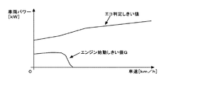
エコ判断部22は、まず、各種センサ2から車速を取得すると共に、HV制御部21から車両パワーを取得する。次に、図3に示すエコ判定しきい値マップを参照して、現在の車速において、車両がエコ運転状態にあると判定できる車両パワーの上限値(以下、この値をエコ判定しきい値と呼ぶ)を求める。このエコ判定しきい値マップには、車速に応じて設定されたエコ判定しきい値が記録されている。また、このエコ判定しきい値マップには、車速に応じて設定された、エンジンの始動が必要な車両パワー(以下、エンジン始動しきい値Gと呼ぶ)も記録されている。
エコ判断部22は、図3に示すエコ判定しきい値マップを参照して、車両パワーのエコ判定しきい値とエンジン始動しきい値とを求めると、これらの値とHV制御部21から取得した現在の車両パワーとに基づいてエコ運転状態量を算出する。エコ運転状態量の具体的な算出方法については、図4を参照しながら説明する。
Next, the amount of eco-driving state generated by the
In this embodiment, the eco-driving state quantity is calculated based on the vehicle power. In a hybrid vehicle, since a motor driven by electric power and an engine are provided, vehicle power is used to express energy generated by both the motor and the engine on one basis. The vehicle power is expressed as the amount of electric power and the power, and can be obtained by the sum of the product of the engine torque and the engine speed and the product of the motor torque and the motor speed.
The
The
図4には、インジケータパネル40のエコ表示部41に表示されるエコバー表示60の一例を示す。
なお、このエコバー表示60は、エコ判断部22から通知されるエコ状態信号等に基づいて、メータECU30の通知制御部31で表示画像を作成することで、エコ表示部41に表示される。
エコバー表示60は、エコ運転状態量をエコ判定しきい値に対する相対量で図形表示するものである。また、エコ運転状態量をエンジン始動しきい値Gに対する相対量で図形表示するものである。
FIG. 4 shows an example of the eco bar display 60 displayed on the
The eco bar display 60 is displayed on the
The eco bar display 60 graphically displays the eco driving state quantity as a relative quantity with respect to the eco judgment threshold value. Further, the eco-driving state quantity is graphically displayed as a relative quantity with respect to the engine start threshold value G.
エコバー表示60には、図4(A),(B),(C),(D)に示すように、ドライバの要求するエコ運転状態量のバー表示61と、HVエコ運転領域62(図4に示すO−A区間)と、エコ運転領域63(図4に示すA−B区間)と、非エコ運転領域64(図4に示すB−C区間)と、回生運転領域(図4に示すO−D間)65と、エンジンの始動しきい値(図4(A),(B),(C),(D)に示すG点)と、エコ判定しきい値(図4(A),(B),(C),(D)に示すB点)とが表示される。
As shown in FIGS. 4 (A), (B), (C), and (D), the eco bar display 60 includes a
図4(A)には、エコ運転状態量のバー表示61をHVエコ運転領域62内に表示した例を示す。エコ運転状態量のバー表示61がHVエコ運転領域62内に表示されている時には、車両がモータで走行している状態を表示している。HVエコ運転領域62では、車両で発生する現在の車両パワーの、エンジン始動しきい値Gに対する相対量でエコ運転状態量を表示している。
HVエコ運転領域62でのエコ運転状態量の算出式を以下に示す。
エコ運転状態量=(現在の車両パワー/エンジン始動しきい値)×50[%]・・・(1)
また、HVエコ運転領域62の上限値が、エンジンの始動しきい値Gとなっている。エンジン始動しきい値Gは、ドライバの要求する車両パワーがエンジン始動しきい値Gよりも高くなった場合に、エンジンを始動させるしきい値である。
FIG. 4A shows an example in which an eco-driving state
A formula for calculating the amount of eco-drive state in the HV
Eco-drive state quantity = (current vehicle power / engine start threshold) x 50 [%] (1)
The upper limit value of the
図4(B)には、エコ運転状態量のバー表示61をエコ運転領域63内に表示した例を示す。ドライバの要求する車両パワーがエンジン始動しきい値Gを超えると、エコ運転状態量がエコ運転領域63に表示される。すなわち、エンジンが始動状態にある時には、エコ運転状態量がエンジン始動しきい値Gの境界上、又はエンジン始動しきい値Gよりもエコ度合いが悪い側に位置するように表示される。
エコ運転状態量のバー表示61がエコ運転領域63内に表示されている時には、車両がモータとエンジンとで走行し、車両の運転状態がエコ運転状態にあることを示している。
エコ運転領域63では、車両の現在の車両パワーと、エンジン始動しきい値と、エコ判定しきい値とを用いて以下に示す式(2)でエコ運転状態量を求める。
エコ運転状態量={(現在の車両パワー−エンジン始動しきい値)/エコ判定しきい値−エンジン始動しきい値}×50[%]+50[%]・・・(2)
FIG. 4B shows an example in which an eco-drive state
When the
In the
Eco-drive state quantity = {(current vehicle power−engine start threshold) / eco determination threshold−engine start threshold} × 50 [%] + 50 [%] (2)
図4(C)には、エコ運転状態量のバー表示61を非エコ運転領域64内に表示した例を示す。ドライバの要求する車両パワーがエコ判定しきい値を超えると、エコ運転状態量が非エコ運転領域64内に表示される。エコ運転状態量のバー表示61が非エコ運転領域64内に表示されているときには、車両が非エコ運転状態にあることを示している。
非エコ運転領域64でのエコ運転状態量も上述した式(2)によって求められる。
FIG. 4C shows an example in which the eco-display state
The amount of eco-drive state in the non-eco-
図4(D)には、エコ運転状態量のバー表示61を回生運転領域65内に表示した例を示す。回生ブレーキ等の操作によって車両の運転状態が回生運転状態にあると、エコ運転状態量のバー表示61が回生運転領域65内に表示される。
回生運転領域65でのエコ運転状態量は以下に示す式(3)によって求められる。
エコ運転状態量=(現在の車両パワー/回生限界値)×−100[%]・・・(3)
なお、回生限界値は、回生によって発電可能な限界値や、充電可能な限界値が設定される。
FIG. 4D shows an example in which the
The eco-driving state quantity in the
Eco-driving state quantity = (current vehicle power / regeneration limit value) × −100 [%] (3)
As the regeneration limit value, a limit value that can be generated by regeneration and a limit value that can be charged are set.
図4(A)〜(D)に示すO点は原点位置であり、エコ運転領域63と回生運転領域65との境界線を示している。エコ運転状態量がO点に表示されると、エコ運転状態量が0%であることを示している。
4 (A) to 4 (D) is an origin position, and indicates a boundary line between the
なお、エンジン始動しきい値Gは、車速やバッテリ残量等によって変動し、最小値は0[kW]となる。すなわち、エンジン始動しきい値が0[kW]のときには、O点とA点とで同じ0[kW]を表すことになる。 The engine start threshold G varies depending on the vehicle speed, the remaining battery level, etc., and the minimum value is 0 [kW]. That is, when the engine start threshold value is 0 [kW], the same 0 [kW] is expressed at the O point and the A point.
また、エコ運転状態量は、図5に示すマップから算出してもよい。マップを利用してエコ運転状態量を算出することで、エコ運転状態量の算出を簡略化することができる。
図5に示すマップは、横軸が車両パワー[kW]を示し、縦軸がエコ運転状態量[%]を表す。マップに示すA’点がエンジンの始動しきい値を示す。また、A点は、バー表示61をHVエコ運転領域62からエコ運転領域63に切り替える表示変更しきい値を表す。A’点とA点でのエコ運転状態量は、50[%]を示す。
また、マップに示すB点がエコ判定しきい値を示す。B点でのエコ運転状態量は、100[%]である。また、C点がエコ運転状態量が150[%]の状態を示し、P点は回生限界値を示す。P点でのエコ運転状態量は、−100[%]を表す。
なお、Px<Ox≦Ax≦A’x≦Bx<Cxとする。Pxはマップに示すP点のX座標値、Oxはマップに示すO(原点)のX座標値、Axはマップに示すA点のX座標値、A’xはマップに示すA’点のX座標値、Bxはマップに示すB点のX座標値、Cxはマップに示すC点のX座標値を示す。
Further, the eco-driving state quantity may be calculated from a map shown in FIG. By calculating the eco-driving state quantity using the map, the calculation of the eco-driving state quantity can be simplified.
In the map shown in FIG. 5, the horizontal axis represents vehicle power [kW], and the vertical axis represents eco-driving state quantity [%]. The point A ′ shown in the map indicates the engine start threshold value. Point A represents a display change threshold value for switching the
Further, the point B shown in the map indicates the eco determination threshold value. The eco-driving state quantity at point B is 100 [%]. Point C indicates a state where the eco-drive state quantity is 150 [%], and point P indicates a regeneration limit value. The eco-driving state quantity at point P represents −100 [%].
Note that Px <Ox ≦ Ax ≦ A′x ≦ Bx <Cx. Px is the X coordinate value of point P shown in the map, Ox is the X coordinate value of O (origin) shown in the map, Ax is the X coordinate value of point A shown in the map, and A'x is the X coordinate value of point A 'shown in the map The coordinate value, Bx, the X coordinate value of point B shown in the map, and Cx, the X coordinate value of point C shown in the map.
エンジンの始動しきい値が0[kW]のときには、常時エンジンが始動状態にある。この場合、アクセルOFF(ドライバの要求する車両パワーが0[kW])であっても、エコ運転状態量がエコ運転領域63内に表示される。すなわち、エンジンは始動状態にあるので、エコ運転状態量は、HVエコ運転領域62を超えて、エコ運転領域63内に表示される。
このとき、ドライバのアクセル踏込み量は0[%]であるのに、エコ運転状態量がエコ運転領域63に表示され、ドライバのアクセル操作と、エコバー表示60とに不整合が生じる。
When the engine starting threshold value is 0 [kW], the engine is always in the starting state. In this case, even when the accelerator is OFF (the vehicle power requested by the driver is 0 [kW]), the eco-driving state quantity is displayed in the
At this time, although the driver's accelerator depressing amount is 0 [%], the eco-driving state amount is displayed in the
そこで、本実施例では、エンジンは始動状態にあるが、ユーザによる運転操作が車両パワーを要求しない操作状態にあるときには、エコ運転状態量がエンジン始動しきい値Gよりもエコ度合いが良い側に位置するようにエコ判断部22で表示を制御する。この他に、ユーザによる運転操作が車両パワーを全く要求しない操作状態にある時や、ユーザによるアクセル操作がアイドル操作状態にある時に、エンジンが始動状態にあればエコ運転状態量がエンジン始動しきい値Gよりもエコ度合いが良い側に位置するように表示を制御する。
なお、エコ運転状態量をエンジン始動しきい値Gよりもエコ度合いが良い側に表示するとは、例えば、回生運転領域65にエコ運転状態量がある場合(エネルギーの発電状態にある場合)を除いて最もエコ度合いが良い状態となるように表示する場合を含む。
Thus, in this embodiment, the engine is in the starting state, but when the driving operation by the user is in an operating state that does not require vehicle power, the eco-driving state amount is on the side where the eco degree is better than the engine starting threshold value G. The
It should be noted that displaying the eco-drive state quantity on the side with a better eco-degree than the engine start threshold G excludes, for example, when the eco-drive state quantity is in the regenerative operation area 65 (when the energy is in a power generation state). Including the case of displaying so that the eco level is the best.
具体的には、エンジンの始動しきい値が0[kW]で、且つドライバの要求する車両パワーが0[kW]の時は、エンジンは始動状態にあるが、エコ運転状態量を0[%]で表示する。すなわち、図6(A)に示すようにエコ運転状態量を表すバー表示61を、原点O(すなわち、0%)に表示させる。
このような表示とすることで、ドライバのアクセル操作と、エコバー表示60との不整合を防ぐことができる。
また、エコ運転領域63に表示するバー表示61と、HVエコ運転領域62に表示するバー表示61とを異なる表示にしてもよい。具体的には、図6(B)に示すようにエンジンの始動しきい値が0[kW](すなわち、エンジン始動状態)で、且つドライバの要求する車両パワーが0[kW]の時には、図6(B)に示すようにHVエコ運転領域62には、バー表示61をエンジン始動しきい値Gまで表示させ、エコ運転領域63には、エコ運転状態量を表すバー表示61を0[%]で表示させる。HVエコ運転領域62にだけバー表示61をエンジン始動しきい値Gまで表示させることで、エンジンが始動状態であることを表示することができる。
さらに、図6(C)に示すように、エコ運転状態量を表すバー表示61は0[%]で表示させ、HVエコ運転領域62を表示しないようにしてもよい。
Specifically, when the engine start threshold is 0 [kW] and the vehicle power required by the driver is 0 [kW], the engine is in the start state but the eco-drive state amount is 0 [%]. ] Is displayed. That is, as shown in FIG. 6 (A), the
With such a display, inconsistency between the driver's accelerator operation and the eco bar display 60 can be prevented.
Further, the
Further, as shown in FIG. 6C, the
次に、インジケータパネル40のエコ表示部41にエコバー表示60を表示させるためのエコ判断部22の処理手順について図7に示すフローチャートを参照しながら説明する。
まずエコ判断部22は、各種センサ2から測定データを入力すると、入力したデータが正常であるか否かを判定する(ステップS1)。エコ判断部22は、入力したデータから各種センサ2が正常に動作しているか否かを判定する。例えば、所定時間以上継続して同一のデータを入力した場合には、各種センサ2に固着異常が発生していると判定する。
エコ判断部22は、測定データが正常ではないと判定すると(ステップS1/NO)、センサ2のフェール時のエコ運転状態量として0%を算出する(ステップS8)。
Next, the processing procedure of the
First, when the measurement data is input from the various sensors 2, the
When the
次に、測定データが正常であると判定すると(ステップS1/YES)、エコ判断部22は、車両の状態がエコ運転表示(エコバー表示60)を提供可能な状態にあるか否かを判定する(ステップS2)。シフトレバーがバックやパーキングの位置にあったり、パワースイッチをオンする信号が入力されている場合には、エコ運転表示が可能な状態ではないと判定する。
エコ判断部22は、エコ運転表示が可能な状態ではないと判定すると(ステップS2/NO)、除外時のエコ運転状態量として0%を算出する(ステップS9)。
Next, when it is determined that the measurement data is normal (step S1 / YES), the
If the
次に、エコ判断部22は、図3に示すマップを参照してエコ判定しきい値を求める(ステップS3)。本実施例ではセンサ2から入力した車速に基づいてエコ判定しきい値を算出する。エコ判断部22は、図3に示すエコ判定しきい値マップをメモリに記憶しており、各種センサ2のうちの車速センサで測定された車速から車両パワーの上限しきい値であるエコ判定しきい値を求める。なお、図3に示すマップは適合によって算出される。
Next, the
次にエコ判断部22は、ステップS3で求めたエコ判定しきい値と、各種センサ2の測定データ等から求めた現在の車両パワーとからエコ運転状態量を算出する(ステップS4)。エコ運転状態量は、上述した式(1)〜(3)で求めることができる。
Next, the
次に、エコ判断部22は、車両が現在停車状態にあるか否かを判定する(ステップS5)。各種センサ2のうちの車速センサから入力した車速に基づいて、車両が停車状態にあるか否かを判定する。例えば、車速が2km/hよりも小さくなった場合には、車両が停止状態にあると判定し、車速が4km/hよりも大きくなった場合には、車両が走行状態にあると判定する。また、車速が2km/h以上で4km/h以下の場合には、停車判定を直ちに行わずに、その後、車速の変化があるまで待機する。
車両が停止状態にあると判定した場合には(ステップS5/YES)、車両停止時のエコ運転状態量として0%を算出する(ステップS10)。
Next, the
If it is determined that the vehicle is in a stopped state (step S5 / YES), 0% is calculated as the eco-driving state amount when the vehicle is stopped (step S10).
次に、エコ判断部22は、算出したエコ運転状態量からバー表示61の表示状態を決定する。この処理の詳細については、図8に示すフローチャートを参照しながら後ほど説明する。
エコバー表示60の表示状態を決定すると、エコ判断部22は、エコ運転状態量や、エコバー表示60の表示状態等を表す情報を含んだエコ状態信号をメータECU30に通知する。メータECU30は、エコ判断部22により通知されたエコ状態信号に基づいてエコバー表示60をエコ表示部41に表示させる。
Next, the
When the display state of the eco bar display 60 is determined, the
次にエンジン始動しきい値が0[kW]で、且つドライバの要求する車両パワーが0[kW]である場合のエコ判断部22の処理手順を図8に示すフローチャートを参照しながら説明する。
まず、エコ判断部22は、エコ運転状態量の現在の表示位置がHVエコ運転領域62のOA区間内にあるか否かを判定する(ステップS11)。すなわち、ドライバの要求する車両パワーがエンジンの始動しきい値Gよりも小さいか否かを判定する(ステップS11)。エコ運転状態量の表示位置がHVエコ運転領域62のOA区間内にあると判定すると(ステップS11/YES)、エコ判断部22はHV制御部21から車両パワーを取得し、ドライバの要求する車両パワーがエンジン始動しきい値G以上に変更されたか否かを判定する(ステップS12)。ドライバの要求する車両パワーがエンジン始動しきい値G以上ではなかった場合には(ステップS12/NO)、エコ判断部22はこの処理を終了する。
また、ドライバの要求する車両パワーがエンジン始動しきい値Gよりも大きい側に変更された場合には(ステップS12/YES)、エコ判断部22は、エンジン始動しきい値Gが0[kW]であるか否かと、ドライバの要求する車両パワーが0[kW]であるか否かとを判定する。
エコ判断部22は、エンジン始動しきい値が0[kW]ではない場合、又はドライバの要求する車両パワーが0[kW]ではない場合には(ステップS13/YES)、ドライバの要求する車両パワーがエンジン始動しきい値Gを超えたと判定し、エコ運転状態量をエンジン始動しきい値Gを超えたエコ運転領域63のAB区間に表示させる(ステップS14)。
また、ステップS13において、エンジン始動しきい値Gが0[kW]である場合や、ドライバの要求する車両パワーが0[kW]である場合には(ステップS13/NO)、エコ判断部22はこの処理を終了する。
Next, the processing procedure of the
First, the
When the vehicle power requested by the driver is changed to a side larger than the engine start threshold G (step S12 / YES), the
When the engine start threshold value is not 0 [kW] or the vehicle power requested by the driver is not 0 [kW] (step S13 / YES), the
In step S13, if the engine start threshold G is 0 [kW] or the vehicle power requested by the driver is 0 [kW] (step S13 / NO), the
また、ステップS11において、エコ運転状態量の現在の表示位置が、HVエコ運転領域62のOA区間内にはない(ステップS11/NO)と判定した場合には、エコ判断部22は、エコ運転状態量がエコ運転領域63のAB区間内にあるか否かを判定する(ステップS15)。
エコ運転状態量がエコ運転領域63のAB区間にはなかった場合には(ステップS15/NO)、エコ判断部22はこの処理を終了する。また、エコ運転状態量がエコ運転領域63のAB区間にあると判定した場合には(ステップS15/YES)、エコ判断部22はHV制御部21から車両パワーを取得し、ドライバの要求する車両パワーとエンジン始動しきい値Gとを比較する(ステップS16)。
ドライバの要求する車両パワーがエンジンの始動しきい値Gよりも小さい側に変更された場合には(ステップS16/YES)、エコ判断部22はエコ運転状態量の表示位置をHVエコ運転領域62のOA区間内に移行させる(ステップS17)。また、ドライバの要求する車両パワーがエンジンの始動しきい値G以上である場合には(ステップS16/NO)、エコ判断部22は、エンジンの始動しきい値Gが0[kW]であり、かつドライバの要求する車両パワーが0[kW]であるか否かを判定する(ステップS18)。
エンジンの始動しきい値Gが0[kW]であり、かつドライバの要求する車両パワーが0[kW]である場合には(ステップS18/YES)、エコ判断部22は、エコ運転状態量を0%で表示させる。すなわち、図4に示すエコバー表示60の原点Oにエコ運転状態量を表示させる。
If it is determined in step S11 that the current display position of the eco-drive state quantity is not within the OA section of the HV eco-drive region 62 (step S11 / NO), the
If the eco-drive state quantity is not in the AB section of the eco-drive region 63 (step S15 / NO), the
When the vehicle power requested by the driver is changed to a side smaller than the engine start threshold G (step S16 / YES), the
When the engine start threshold G is 0 [kW] and the vehicle power requested by the driver is 0 [kW] (step S18 / YES), the
以上の説明より明らかなように、本実施例はエンジンの始動しきい値が0[kW]で、且つドライバの要求する車両パワーが0[kW]の時は、エコ運転状態量を0[%]で表示する。すなわち、エンジンは駆動状態にあるが、エコ運転状態量は0[%]で表示する。このような表示とすることで、ドライバのアクセル操作と、エコバー表示60との表示の不整合を防ぐことができる。 As is clear from the above description, in this embodiment, when the engine start threshold is 0 [kW] and the vehicle power required by the driver is 0 [kW], the eco-driving state amount is 0 [%]. ] Is displayed. That is, although the engine is in a driving state, the eco-driving state amount is displayed as 0 [%]. By using such a display, it is possible to prevent display inconsistency between the driver's accelerator operation and the eco bar display 60.
上述した実施例は本発明の好適な実施の例である。但し、これに限定されるものではなく、本発明の要旨を逸脱しない範囲内において種々変形実施が可能である。
例えば、上述した実施例では、HV−ECU20にエコ判断部22を設けているが、図9に示すようにメータECU30にエコ判断部22を設けたエコ運転支援システム1Bとしてもよい。また、図示はしていないが、車内通信バスにナビECUを接続し、このナビECUにエコ判断部22を設けることもできる。
The embodiment described above is a preferred embodiment of the present invention. However, the present invention is not limited to this, and various modifications can be made without departing from the scope of the present invention.
For example, in the embodiment described above, the
また、図4に示すエコバー表示60の例では、回生側の表示領域として、回生運転領域65だけを表示しているが、図10(A)に示すように回生運転領域65側の非エコ運転領域66を表示させてもよい。この非エコ運転領域66は、回生ブレーキだけでなく、機械式のブレーキを使用したブレーキ操作が行われている状態を表示する。
また、図10(A)に示すようにエコバー表示60と共に、車両の運転状態がエコ運転状態にあるか否かをLED等のランプの点灯、消灯で表示するエコランプ70の表示を表示させてもよい。
さらに、上述したエコバー表示60に代えて、図10(B)に示すスピードメータのような円表示を採用してもよい。
In the example of the eco bar display 60 shown in FIG. 4, only the
Further, as shown in FIG. 10A, along with the eco bar display 60, the display of the
Furthermore, instead of the eco bar display 60 described above, a circle display such as a speedometer shown in FIG.
また、上述した実施例では、エコ判断部22を車両の制御装置(HV−EUC)に設けて、車速等に基づいて車両のエコ運転状態量を求めて、リアルタイムにこれを表示している。これ以外に、エコ判断部22で求めた車速とエコ運転状態量を記録媒体等に記録しておき、降車後にコンピュータ装置に記録媒体の記録内容を読み込んで、エコ運転状態量の経時的な変化を表示させるようにしてもよい。
Further, in the above-described embodiment, the
1 エコ運転支援システム
2 各種センサ
10 パワートレインECU
20 HV−ECU
21 HV制御部
22 エコ判断部
30 メータECU
31 通知制御部
40 インジケータパネル
41 エコ表示部
50 モータ・ジェネレータECU
1 Eco-driving support system 2
20 HV-ECU
21
31
Claims (5)
車両で発生する車両パワーに基づいて前記エコ運転状態量を算出するエコ運転状態量算出手段と、
前記エコ運転状態量を、前記エンジンを始動させる車両パワーを示す始動しきい値に対する相対量で図形表示させるものであり、前記エンジンが作動している状態にあるときには、前記エコ運転状態量が前記始動しきい値の境界上、もしくは前記エコ運転状態量が前記始動しきい値よりもエコ度合いが悪い側に位置するように表示を制御する表示制御手段と、を備え、
前記表示制御手段は、前記エンジンは作動している状態にあるが、ユーザによる運転操作が車両パワーを要求しない操作状態にあるときには、前記エコ運転状態量を前記始動しきい値よりもエコ度合いが良い側に位置するように表示させることを特徴とするエコ運転支援装置。 An eco-driving support device that displays an eco-driving state amount representing an eco-level of a driving state in a hybrid vehicle including an engine and a motor as drive sources,
Eco-driving state amount calculating means for calculating the eco-driving state amount based on vehicle power generated in the vehicle;
The eco-driving state quantity is graphically displayed as a relative amount with respect to a starting threshold value indicating a vehicle power for starting the engine. When the engine is in an operating state, the eco-driving state quantity is Display control means for controlling the display so that the eco-drive state quantity is located on the side where the eco degree is worse than the start threshold, on the boundary of the start threshold,
The display control means is configured such that when the engine is in an operating state, but the driving operation by the user is in an operation state that does not require vehicle power, the eco-driving state amount is more ecological than the start threshold value. An eco-driving support device characterized by being displayed so as to be positioned on the good side.
車両で発生する車両パワーに基づいて前記エコ運転状態量を算出するエコ運転状態量算出手段と、
前記エコ運転状態量を、前記エンジンを始動させる車両パワーを示す始動しきい値に対する相対量で図形表示させるものであり、前記エンジンが作動している状態にあるときには、前記エコ運転状態量が前記始動しきい値の境界上、もしくは、前記エコ運転状態量が前記始動しきい値よりもエコ度合いが悪い側に位置するように表示を制御する表示制御手段と、を備え、
前記表示制御手段は、前記始動しきい値を固定位置に表示するが、前記エンジンが作動している状態で、かつ、ユーザによる運転操作が車両パワーを要求しない操作状態にあるときには、前記エコ運転状態量を前記始動しきい値よりもエコ度合いが良い側に位置するように表示させることを特徴とするエコ運転支援装置。 An eco-driving support device that displays an eco-driving state amount representing an eco-level of a driving state in a hybrid vehicle including an engine and a motor as drive sources,
Eco-driving state amount calculating means for calculating the eco-driving state amount based on vehicle power generated in the vehicle;
The eco operation state quantity, and also to the Ru is graphically displayed in relative amounts with respect to the startup threshold shows the vehicle power to start the engine, in a state in which the engine is operating, the eco-drive amount on the boundary of the startup threshold value, or, and a display control means for controlling the Viewing to be located in the eco degree worse side than the eco-drive state quantity the starting threshold,
The display control means displays the starting threshold value at a fixed position, but when the engine is operating and the driving operation by the user is in an operating state not requiring vehicle power, the eco-driving is performed. An eco-driving support device, wherein the state quantity is displayed so as to be located on the side where the eco degree is better than the starting threshold value.
車両で発生する車両パワーに基づいて前記エコ運転状態量を算出するステップと、
前記エコ運転状態量を、前記エンジンを始動させる車両パワーを示す始動しきい値に対する相対量で表示手段に図形表示させるものであり、前記エンジンが作動している状態にあるときには、前記エコ運転状態量が前記始動しきい値の境界上、もしくは前記エコ運転状態量が前記始動しきい値よりもエコ度合いが悪い側に位置するように前記表示手段に表示させるステップと、
前記エンジンは作動している状態にあるが、ユーザによる運転操作が車両パワーを要求しない操作状態にあるときには、前記エコ運転状態量を前記始動しきい値よりもエコ度合いが良い側に位置するように前記表示手段に表示させるステップと、
を有することを特徴とするエコ運転支援方法。 In a hybrid vehicle having an engine and a motor as drive sources, an eco-driving support method for supporting a driver's driving operation by displaying an eco-driving state amount representing an eco degree of driving state on a display means,
Calculating the eco-driving state quantity based on vehicle power generated in the vehicle;
The eco-driving state quantity is displayed graphically on the display means as a relative amount with respect to a starting threshold value indicating vehicle power for starting the engine, and when the engine is in an operating state, the eco-driving state quantity Displaying on the display means such that the amount is on the boundary of the starting threshold value, or the eco-driving state amount is on the side where the eco degree is worse than the starting threshold value;
The engine is in an operating state, but when the driving operation by the user is in an operation state that does not require vehicle power, the eco-driving state amount is positioned on the side where the eco degree is better than the start threshold value. Displaying on the display means;
An eco-driving support method characterized by comprising:
Priority Applications (1)
| Application Number | Priority Date | Filing Date | Title |
|---|---|---|---|
| JP2013004648A JP5460896B2 (en) | 2013-01-15 | 2013-01-15 | Eco driving support device and method |
Applications Claiming Priority (1)
| Application Number | Priority Date | Filing Date | Title |
|---|---|---|---|
| JP2013004648A JP5460896B2 (en) | 2013-01-15 | 2013-01-15 | Eco driving support device and method |
Related Parent Applications (1)
| Application Number | Title | Priority Date | Filing Date |
|---|---|---|---|
| JP2008197083A Division JP5368025B2 (en) | 2008-07-30 | 2008-07-30 | Eco driving support device and method |
Publications (2)
| Publication Number | Publication Date |
|---|---|
| JP2013107641A JP2013107641A (en) | 2013-06-06 |
| JP5460896B2 true JP5460896B2 (en) | 2014-04-02 |
Family
ID=48704840
Family Applications (1)
| Application Number | Title | Priority Date | Filing Date |
|---|---|---|---|
| JP2013004648A Active JP5460896B2 (en) | 2013-01-15 | 2013-01-15 | Eco driving support device and method |
Country Status (1)
| Country | Link |
|---|---|
| JP (1) | JP5460896B2 (en) |
Families Citing this family (1)
| Publication number | Priority date | Publication date | Assignee | Title |
|---|---|---|---|---|
| BR112020011906A2 (en) * | 2017-12-15 | 2020-11-24 | Nissan Motor Co., Ltd. | operational status display method and operational status display system |
Family Cites Families (3)
| Publication number | Priority date | Publication date | Assignee | Title |
|---|---|---|---|---|
| JP4458020B2 (en) * | 2005-11-01 | 2010-04-28 | トヨタ自動車株式会社 | Hybrid vehicle driver support system. |
| JP4325632B2 (en) * | 2006-03-24 | 2009-09-02 | トヨタ自動車株式会社 | Fuel consumption display device for hybrid vehicles |
| JP4155321B2 (en) * | 2006-09-25 | 2008-09-24 | トヨタ自動車株式会社 | Hybrid vehicle display device, hybrid vehicle, and hybrid vehicle display method |
-
2013
- 2013-01-15 JP JP2013004648A patent/JP5460896B2/en active Active
Also Published As
| Publication number | Publication date |
|---|---|
| JP2013107641A (en) | 2013-06-06 |
Similar Documents
| Publication | Publication Date | Title |
|---|---|---|
| JP5086201B2 (en) | Eco driving support device and method | |
| JP5368025B2 (en) | Eco driving support device and method | |
| JP4458020B2 (en) | Hybrid vehicle driver support system. | |
| US9108629B2 (en) | Driving assistance device | |
| US9202378B2 (en) | Driving assistance apparatus | |
| JP2012116457A (en) | Method and system for controlling acceleration torque of hybrid vehicle | |
| JP5296449B2 (en) | Eco driving support device | |
| JP5143540B2 (en) | Eco driving support device | |
| JP5337501B2 (en) | Eco driving support device | |
| JP5460896B2 (en) | Eco driving support device and method | |
| JP5387152B2 (en) | Vehicle travel control device | |
| JP4456630B2 (en) | Eco operation status display device | |
| JP2009156132A (en) | Eco drive assist device | |
| JP5922427B2 (en) | vehicle | |
| KR101673747B1 (en) | Apparatus for displaying eco guide in vehicle cluster and method thereof | |
| US9180788B2 (en) | Fuel-saving rating device and power amount management device | |
| JP4456631B2 (en) | Eco driving support device | |
| JP6634986B2 (en) | Travel control device | |
| JP4376935B2 (en) | Eco driving support device | |
| KR101683523B1 (en) | Apparatus and method for providing distance to entry of vehicle | |
| US11602993B1 (en) | System and method for adjusting the transparency of a digital needle | |
| JP6982785B2 (en) | Vehicle instruments | |
| JP6575206B2 (en) | Fuel saving driving degree display device and fuel saving driving degree display method | |
| KR101665620B1 (en) | Driving guide system for hybrid vehicle and method thereof | |
| JP5472127B2 (en) | Driving support device |
Legal Events
| Date | Code | Title | Description |
|---|---|---|---|
| A977 | Report on retrieval |
Free format text: JAPANESE INTERMEDIATE CODE: A971007 Effective date: 20130919 |
|
| A131 | Notification of reasons for refusal |
Free format text: JAPANESE INTERMEDIATE CODE: A131 Effective date: 20131001 |
|
| A521 | Request for written amendment filed |
Free format text: JAPANESE INTERMEDIATE CODE: A523 Effective date: 20131129 |
|
| TRDD | Decision of grant or rejection written | ||
| A01 | Written decision to grant a patent or to grant a registration (utility model) |
Free format text: JAPANESE INTERMEDIATE CODE: A01 Effective date: 20131224 |
|
| A61 | First payment of annual fees (during grant procedure) |
Free format text: JAPANESE INTERMEDIATE CODE: A61 Effective date: 20140114 |
|
| R150 | Certificate of patent or registration of utility model |
Ref document number: 5460896 Country of ref document: JP Free format text: JAPANESE INTERMEDIATE CODE: R150 Free format text: JAPANESE INTERMEDIATE CODE: R150 |
|
| R250 | Receipt of annual fees |
Free format text: JAPANESE INTERMEDIATE CODE: R250 |
|
| R250 | Receipt of annual fees |
Free format text: JAPANESE INTERMEDIATE CODE: R250 |
|
| R250 | Receipt of annual fees |
Free format text: JAPANESE INTERMEDIATE CODE: R250 |
|
| R250 | Receipt of annual fees |
Free format text: JAPANESE INTERMEDIATE CODE: R250 |
|
| R250 | Receipt of annual fees |
Free format text: JAPANESE INTERMEDIATE CODE: R250 |