WO2010001684A1 - Communication system - Google Patents
Communication system Download PDFInfo
- Publication number
- WO2010001684A1 WO2010001684A1 PCT/JP2009/060311 JP2009060311W WO2010001684A1 WO 2010001684 A1 WO2010001684 A1 WO 2010001684A1 JP 2009060311 W JP2009060311 W JP 2009060311W WO 2010001684 A1 WO2010001684 A1 WO 2010001684A1
- Authority
- WO
- WIPO (PCT)
- Prior art keywords
- address
- mobile station
- header compression
- connection device
- base station
- Prior art date
Links
Images


Classifications
-
- H—ELECTRICITY
- H04—ELECTRIC COMMUNICATION TECHNIQUE
- H04L—TRANSMISSION OF DIGITAL INFORMATION, e.g. TELEGRAPHIC COMMUNICATION
- H04L61/00—Network arrangements, protocols or services for addressing or naming
- H04L61/09—Mapping addresses
- H04L61/10—Mapping addresses of different types
- H04L61/103—Mapping addresses of different types across network layers, e.g. resolution of network layer into physical layer addresses or address resolution protocol [ARP]
-
- H—ELECTRICITY
- H04—ELECTRIC COMMUNICATION TECHNIQUE
- H04L—TRANSMISSION OF DIGITAL INFORMATION, e.g. TELEGRAPHIC COMMUNICATION
- H04L49/00—Packet switching elements
- H04L49/90—Buffering arrangements
-
- H—ELECTRICITY
- H04—ELECTRIC COMMUNICATION TECHNIQUE
- H04L—TRANSMISSION OF DIGITAL INFORMATION, e.g. TELEGRAPHIC COMMUNICATION
- H04L61/00—Network arrangements, protocols or services for addressing or naming
- H04L61/50—Address allocation
- H04L61/5007—Internet protocol [IP] addresses
- H04L61/5014—Internet protocol [IP] addresses using dynamic host configuration protocol [DHCP] or bootstrap protocol [BOOTP]
-
- H—ELECTRICITY
- H04—ELECTRIC COMMUNICATION TECHNIQUE
- H04L—TRANSMISSION OF DIGITAL INFORMATION, e.g. TELEGRAPHIC COMMUNICATION
- H04L69/00—Network arrangements, protocols or services independent of the application payload and not provided for in the other groups of this subclass
- H04L69/04—Protocols for data compression, e.g. ROHC
-
- H—ELECTRICITY
- H04—ELECTRIC COMMUNICATION TECHNIQUE
- H04L—TRANSMISSION OF DIGITAL INFORMATION, e.g. TELEGRAPHIC COMMUNICATION
- H04L69/00—Network arrangements, protocols or services independent of the application payload and not provided for in the other groups of this subclass
- H04L69/22—Parsing or analysis of headers
-
- H—ELECTRICITY
- H04—ELECTRIC COMMUNICATION TECHNIQUE
- H04W—WIRELESS COMMUNICATION NETWORKS
- H04W28/00—Network traffic management; Network resource management
- H04W28/02—Traffic management, e.g. flow control or congestion control
- H04W28/06—Optimizing the usage of the radio link, e.g. header compression, information sizing, discarding information
-
- H—ELECTRICITY
- H04—ELECTRIC COMMUNICATION TECHNIQUE
- H04W—WIRELESS COMMUNICATION NETWORKS
- H04W8/00—Network data management
- H04W8/26—Network addressing or numbering for mobility support
Definitions
- the present invention relates to a communication system, a connection device, a connection method, and a program for providing a service to a mobile terminal.
- the Mobile WiMAX system which applies WiMAX (Worldwide Interoperability for Microwave Access) technology, which has been attracting attention in recent years, to mobile communications, is an MS (Mobile Station), which is a mobile station that receives services by subscribing to the system, and an MS.
- MS Mobile Station
- ASN-GW Access Service Network Gateway
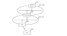
- FIG. 1 is a diagram illustrating a configuration example of a general WiMAX system.
- DHCP server 1003 an ASN-GW 1004, a BS 1005, and an MS 1006.
- ASN-GW 1004 a GPRS Support Node
- MS 1006 The WiMAX system shown in FIG.
- the DHCP server 1003 is a server having a DHCP (Dynamic Host Configuration Protocol) function that exists in a CSN (Connectivity Service Network) 1001 and automatically sets an IP (Internet Protocol) address in the MS 1006.
- DHCP Dynamic Host Configuration Protocol
- CSN Connectivity Service Network
- IP Internet Protocol
- the ASN-GW 1004 is a connection device for connecting the CSN 1001 and an ASN (Access Service Network) 1002.
- the ASN-GW 1004 is connected to the DHCP server 1003 and the BS 1005.
- BS 1005 is a base station that exists in ASN 1002 and is configured to be connectable with MS 1006.
- MS 1006 is a mobile station that can communicate with CSN 1001 via BS 1005 and ASN-GW 1004.
- a technique for performing communication by compressing a packet header of the packet data in order to save communication bandwidth is disclosed in Japanese Patent Application Laid-Open No. 2005-124077. It is disclosed in the publication.
- An example of this technique is a PHS (Payload Header Suppression) rule.
- the PHS rule is a payload header compression mechanism that can efficiently operate a communication line by reducing the bandwidth used by deleting redundant packet header information.
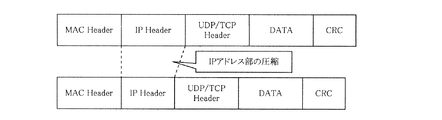
- FIG. 2 is a diagram illustrating an example of a state of compression of a packet header to which a predetermined PHS rule is applied.
- a packet header to which a predetermined PHS rule is applied includes a MAC (Media Access Control) header, an IP header, a UDP (User Datagram Protocol) / TCP (Transmission Control Protocol) header, data, and a CRC (CedicRiclicric).
- MAC Media Access Control
- IP IP address
- UDP User Datagram Protocol
- TCP Transmission Control Protocol
- CRC CedicRiclicric
- FIG. 3 is a diagram for explaining the PHS rule.
- a packet header composed of A, B, C, D, and E is transmitted from a transmitting side that is a transmitting device to a receiving side that is a receiving device via a wireless section.
- A, B, C, D and E are data in byte units.
- PHSM PHS-Mask
- PHS-Field the content (information) of the data to be compressed
- the desired data Compression is possible.
- A, C, and E are compressed and transmitted. That is, as shown in FIG. 3, the packet header is composed of B and D in the radio section.
- the “PHSF” in which the value is set is transmitted from the transmitting side to the receiving side, thereby being compressed. A, C, and E are restored on the receiving side.
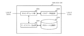
- FIG. 4 is a diagram showing an example of the internal configuration of the ASN-GW 1004 shown in FIG.
- the ASN-GW 1004 shown in FIG. 1 includes a BS interface unit 1041, a service flow generation unit 1042, a CSN data transfer unit 1043, and a PHS rule storage unit 1044.
- the BS interface unit 1041 has an interface function with the BS 1005.
- the service flow generation unit 1042 reads the PHS rule stored in the PHS rule storage unit 1044 and transmits the read PHS rule to the BS 1005 via the BS interface unit 1041.
- the CSN data transfer unit 1043 has an interface function with the CSN 1001.
- the PHS rule storage unit 1044 stores a PHS rule created manually in advance.
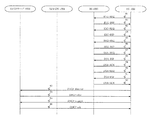
- FIG. 5 is a sequence diagram for explaining a method of joining the MS 1006 to the WiMAX system shown in FIG.
- an RNG-REQ (Ranging-Request) message that is a ranging request signal is transmitted from the MS 1006 to the BS 1005.
- an RNG-RSP (Ranging-Response) message that is a response signal of the RNG-REQ message is transmitted from the BS 1005 to the MS 1006.
- an SBC-REQ (Station Basic Capability-Request) message is transmitted from the MS 1006 to the BS 1005 in step 83 in order to negotiate various capabilities (capacity) information.
- an SBC-RSP (Station Basic Capability-Response) message that is a response signal of the SBC-REQ message is transmitted from the BS 1005 to the MS 1006.
- a REG-REQ (Registration-Request) message which is a registration request signal, is transmitted from the MS 1006 to the BS 1005.
- a REG-RSP Registration-Response (REG-RSP Registration-Response) message that is a response signal of the REG-REQ message is transmitted from the BS 1005 to the MS 1006.
- a DSA-REQ (Dynamic Service Addition-Request) / RSP / ACK (Acknowledge) message for establishing a new service flow is transmitted between BS 1005 and MS 1006 once for each of the uplink and downlink in steps 87-92. Sent and received between.
- the DSA-REQ message transmitted from the BS 1005 to the MS 1006 includes a PHS rule.
- an IP address is requested from the MS 1006 to the DHCP server 1003 via the BS 1005 and the ASN-GW 1004, and an IP address is assigned from the DHCP server 1003 to the MS 1006.
- the first problem is that since the PHS rule is created manually, the compression location cannot be specified unless the contents of the packet are known in advance, and the PHS rule cannot be generated.
- the second problem is that only the fixed IP address can be handled because the PHS rule cannot be generated unless the packet contents are known in advance. That is, when an IP address is assigned using DHCP, the IP address portion cannot be compressed.
- An object of the present invention is to provide a communication system, a connection device, a connection method, and a program that solve the above-described problems.
- the present invention provides: In a communication system comprising a mobile station, a base station that performs communication by applying a header compression rule that compresses a packet header between the mobile station, and a connection device that connects the base station to a predetermined network,
- the mobile station subscribes to the communication system, the mobile station transmits the physical address assigned to the mobile station to the connection device via the base station
- the connection device includes an address storage unit that stores a physical address and an IP address assigned to the mobile station in association with each other, and an IP address corresponding to the physical address transmitted from the mobile station is the address. Searching from the storage unit, generating the header compression rule according to the searched IP address, and transmitting the generated header compression rule to the mobile station via the base station.
- connection device connected to a base station that performs communication by applying a header compression rule for compressing a packet header with a mobile station,
- An address storage unit that stores a physical address and an IP address assigned to the mobile station in association with each other;
- a service flow generation unit that searches the address storage unit for an IP address corresponding to a physical address transmitted from the mobile station, and generates the header compression rule according to the searched IP address;
- a base station interface unit that transmits the generated header compression rule to the mobile station via the base station.
- a communication system comprising a mobile station, a base station that performs communication by applying a header compression rule that compresses a packet header between the mobile station, and a connection device that connects the base station to a predetermined network
- a connection method in which When the mobile station subscribes to the communication system, the physical address given to the mobile station is transmitted to the connection device via the base station; The connection device stores the physical address and the IP address assigned to the mobile station in association with each other in a table of the connection device; The connection device searches the table for an IP address corresponding to the physical address transmitted from the mobile station; The connection device generating the header compression rule according to the searched IP address; The connection device includes a step of transmitting the generated header compression rule to the mobile station via the base station.
- a connection method for connecting a mobile station and a network via a base station Storing the physical address and IP address assigned to the mobile station in association with each other; Searching the stored association for an IP address corresponding to the physical address transmitted from the mobile station; Generating a header compression rule for compressing a packet header according to the retrieved IP address; Transmitting the generated header compression rule to the mobile station via the base station.
- a program that is executed by a computer connected to a base station that performs communication by applying a header compression rule for compressing a packet header with a mobile station, A procedure in which a physical address and an IP address assigned to the mobile station are associated in advance and stored in a table provided in the computer; A procedure for searching the table for an IP address corresponding to a physical address transmitted from the mobile station; Generating the header compression rule according to the retrieved IP address; A procedure for transmitting the generated header compression rule to the mobile station via the base station.
- the physical address assigned to the mobile station is transmitted to the connection device via the base station, and the connection device is assigned to the mobile station.
- the physical address and the IP address associated with each other are stored in advance in a table of the connection device, the IP address corresponding to the physical address transmitted from the mobile station is retrieved from the table, and the header corresponding to the retrieved IP address Since the compression rule is generated and the generated header compression rule is transmitted to the mobile station via the base station, the PHS rule that is the header compression rule can be easily generated and applied.
- FIG. 2 is a diagram illustrating an example of an internal configuration of an ASN-GW illustrated in FIG. It is a sequence diagram for demonstrating the subscription method of MS to the WiMAX system shown in FIG. It is a figure which shows one Embodiment of the communication system of this invention.
- FIG. 7 is a diagram illustrating an example of an internal configuration of the ASN-GW illustrated in FIG. 6. It is a figure which shows an example of the structure of the address corresponding
- FIG. 6 A sequence for explaining a method of joining the MS to the communication system shown in FIG. 6 when the correspondence between the MAC address assigned to the MS and the IP address is stored in the address correspondence table shown in FIG. FIG. It is a figure which shows header compression of an upstream signal. It is a figure which shows header compression of a downstream signal. It is a figure which shows an example of the DSA-REQ message in which the PHS rule was included.
- FIG. 6 is a diagram showing an embodiment of the communication system of the present invention.
- this embodiment is a WiMAX system provided with a DHCP server 103, an ASN-GW 104, a BS 105, and an MS.
- the DHCP server 103 is a server that exists in a CSN (Connectivity Service Network) 101 and has a DHCP (Dynamic Host Configuration Protocol) function that is a protocol for automatically setting an IP address in the MS 106.
- the DHCP server 103 may be the same as the DHCP server 1003 shown in FIG.
- the ASN-GW 104 is a connection device for connecting the CSN 101 and the ASN (Access Service Network) 102.
- the ASN-GW 104 is connected to the DHCP server 103 and the BS 105.
- BS 105 is a base station that exists in ASN 102 and is configured to be connectable with MS 106. Further, the BS 105 receives a request from the MS 106 and performs a subscription (Network Entry) process of the MS 106.
- MS 106 is a mobile station that can communicate with CSN 101 via BS 105 and ASN-GW 104.
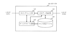
- FIG. 7 is a diagram showing an example of the internal configuration of the ASN-GW 104 shown in FIG.
- the ASN-GW 104 shown in FIG. 6 includes a BS interface unit 141, a service flow generation unit 142, a CSN data transfer unit 143, and an address correspondence table 144.
- the BS interface unit 141 is a base station interface unit having an interface function with the BS 105.
- the service flow generation unit 142 reads the IP address stored in the address correspondence table 144, and generates a PHS rule that is a header compression rule based on the read IP address. Further, a service flow including the generated PHS rule is generated and transmitted to the BS 105 via the BS interface unit 141.
- the CSN data transfer unit 143 has an interface function with the CSN 101.
- the address correspondence table 144 is an address storage unit that stores a correspondence between a MAC address that is a physical address assigned to the MS 106 and an IP address.
- FIG. 8 is a diagram showing an example of the structure of the address correspondence table 144 shown in FIG.
- the MAC address which is the physical address assigned to each MS, and the IP address are stored in association with each other.
- This IP address is the IP address acquired by the DHCP server 103 by the MS.
- the MAC address “01-0A-03-0B-05-0C” and the IP address “111.11.1.1.1” are stored in association with each other. This indicates that the IP address of the MS whose MAC address is “01-0A-03-0B-05-0C” is “111.11.1.1”.
- the MAC address “02-0D-04-0E-06-0F” and the IP address “222.22.2.2” are stored in association with each other. This indicates that the IP address of the MS whose MAC address is “02-0D-04-0E-06-0F” is “222.22.2.2”.
- the MAC address “07-0A-08-0B-09-0C” and the IP address “333.33.3.3” are stored in association with each other.
- the IP address of the MS whose MAC address is “07-0A-08-0B-09-0C” is “333.3.33.3”.
- the correspondence between the MAC address and the IP address shown in FIG. 8 is three sets, it goes without saying that the correspondence stored in the address correspondence table 144 is not limited to three sets. Further, the MAC address and the IP address shown in FIG. 8 use a simple sequence of numbers for convenience of explanation, and are irrelevant to actual ones, and may or may not exist.
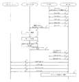
- FIG. 9 shows a method for joining the MS 106 to the communication system shown in FIG. 6 when the correspondence between the MAC address assigned to the MS 106 and the IP address is stored in the address correspondence table 144 shown in FIG. It is a sequence diagram for demonstrating.
- step 1 an RNG-REQ message that is a ranging request signal is transmitted from the MS 106 to the BS 105.
- the MAC address assigned to the MS 106 is transmitted using the RNG-REQ message.
- step 2 an RNG-RSP message that is a response signal of the RNG-REQ message is transmitted from the BS 105 to the MS 106.
- step 3 an SBC-REQ message is transmitted from the MS 106 to the BS 105 in order to negotiate various capabilities (capacity) information. Then, in step 4, an SBC-RSP message that is a response signal of the SBC-REQ message is transmitted from the BS 105 to the MS 106.
- step 5 a REG-REQ message that is a registration request signal is transmitted from the MS 106 to the BS 105. Then, in step 6, a REG-RSP message that is a response signal of the REG-REQ message is transmitted from the BS 105 to the MS 106.
- steps 2 to 6 is the same as the processing of steps 82 to 86 described with reference to FIG.
- the MAC address of the MS 106 transmitted from the MS 106 in Step 1 is transmitted from the BS 105 to the ASN-GW 104 in Step 7.
- the MAC address of the MS 106 transmitted from the BS 105 is received by the BS interface unit 141 of the ASN-GW 104, and the IP address corresponding to the MAC address is retrieved from the address correspondence table 144 by the service flow generation unit 142 in step 8.
- the correspondence between the MAC address “01-0A-03-0B-05-0C” assigned to the MS 106 and the IP address “111.11.1.1” is stored in the address correspondence table 144 Therefore, the IP address “111.11.1.1” corresponding to the MAC address “01-0A-03-0B-05-0C” is acquired in Step 9.
- the service flow generation unit 142 generates a PHS rule in step 10 based on the acquired IP address.
- a PHS rule is generated between the BS 105 and the MS 106 for header compression in which an upstream signal (a signal from the MS 106 to the BS 105) omits a source address among IP headers included in the upstream signal.
- an upstream signal a signal from the MS 106 to the BS 105
- a PHS rule is generated for the downlink signal (the signal from the BS 105 to the MS 106) for header compression in which the destination address is omitted from the IP header included in the downlink signal.
- FIG. 10 is a diagram showing header compression of the upstream signal.
- the source address is omitted from the IP header of the upstream signal.
- the other fields are fields that are generally used, and are not particularly described here.
- FIG. 11 is a diagram showing header compression of the downlink signal.
- the Destination address is omitted from the IP header of the downstream signal.
- the other fields are the same as those shown in FIG.
- a PHS rule indicating that the above-described field is omitted is generated. Specifically, the following information is included in the generated PHS rule.
- PHSF PHS-Field
- PHSM PHS-MASK
- PHSS PHS-Size
- PHSF indicates header information to be compressed (omitted). That is, it is information indicating the data itself contained in the portion to be compressed (omitted). This information is used when the compressed header is restored on the receiving side.
- PHSM is information indicating a position to be compressed (omitted) in the header. This information indicates the position of the part, for example, when compressing a part that does not change during notification, such as an IP address or a port number. When this PHSM indicates the position of the IP address, the IP address is indicated in the PHSF.
- PHSS is information indicating the number of data to be compressed by this PHS rule, and matches the length of PHSF.
- the PHS rule composed of these pieces of information is output from the service flow generation unit 142 to the BS interface unit 141 and transmitted from the BS interface unit 141 to the BS 105 in step 11.
- a DSA-REQ / RSP / ACK message for establishing a new service flow is transmitted / received between the BS 105 and the MS 106 once in uplink and downlink in steps 12-14.
- the DSA-REQ message which is a service flow establishment request signal transmitted from the BS 105 to the MS 106, includes the PHS rule transmitted from the ASN-GW 104 in Step 11.
- FIG. 12 is a diagram illustrating an example of a DSA-REQ message including a PHS rule.
- the DSA-REQ message includes a PHS rule.
- whether the DSA-REQ message includes the PHS rule is determined based on whether the Associated PHSI (PHS-Index) illustrated in FIG. 12 is included in the Packet Classifier rule.
- PHS-Index Associated PHSI
- TLV Type, Length, Value
- the PHSI is a field composed of 1 byte, and is an Index indicating the number of the PHS rule that follows. Note that the same number is indicated in Associated PHSI and PHSI.
- PHSF PHSM
- PHSS PHSS
- PHSV PHS-Valid
- Verify field for confirming whether or not the value compressed at the time of compression by this PHS rule is correct. For example, a result obtained by performing a predetermined calculation on the PHS rule field may be indicated.
- the other fields of the DSA-REQ are the same as general fields, and thus will not be described here.
- an IP address is requested from the MS 106 to the DHCP server 103 via the BS 105 and the ASN-GW 104, and an IP address is assigned from the DHCP server 103 to the MS 106.
- the IP address assignment method by the DHCP server 103 is the same as a general method.
- the IP address assigned here is the same as the previous time, that is, the IP address stored in the address correspondence table 144. Therefore, after that, in step 19, communication using the PHS rule is performed between the BS 105 and the MS 106.
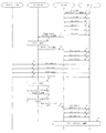
- FIG. 13 shows a method for joining the MS 106 to the communication system shown in FIG. 6 when the correspondence between the MAC address assigned to the MS 106 and the IP address is not stored in the address correspondence table 144 shown in FIG. It is a sequence diagram for demonstrating.
- Step 1 to Step 8 The processing from Step 1 to Step 8 is the same as the processing described with reference to FIG.
- the service flow generation unit 142 since the correspondence between the MAC address assigned to the MS 106 and the IP address is not stored in the address correspondence table 144, it corresponds to the MAC address “05-0A-03-0B-01-0C”.
- the IP address to be acquired is not acquired. Therefore, in step 31, the service flow generation unit 142 generates a signal indicating that there is no IP address, and the signal is transmitted to the BS 105 via the BS interface unit 141, whereby the MAC address “05-0A-03” is generated. It is notified that the IP address corresponding to “ ⁇ 0B-01-0C” does not exist in the address correspondence table.
- a DSA-REQ / RSP / ACK message for establishing a new service flow is transmitted / received between the BS 105 and the MS 106 once in uplink and downlink in steps 32-34.
- normal DSA-REQ / RSP / ACK messages are exchanged.
- an IP address is requested from the MS 106 to the DHCP server 103 via the BS 105 and the ASN-GW 104, and an IP address is assigned from the DHCP server 103 to the MS 106.
- an IP address is assigned from the DHCP server 103 to the MS 106, but the DHCP data transfer is detected by the CSN data transfer unit 143, and the IP address is acquired in step 39.
- the acquired IP address is associated with the MAC address by the CSN data transfer unit 143 in step 40 and stored in the address correspondence table 144.
- the CSN data transfer unit 143 notifies the service flow generation unit 142 that the correspondence between the MAC address and the IP address is stored in the address correspondence table 144.
- the service flow generation unit 142 makes an inquiry to the address correspondence table 144, and a PHS rule is generated based on the IP address in step 41.
- the method for generating the PHS rule is the same as the method described using Step 10 shown in FIG.
- the generated PHS rule is output from the service flow generation unit 142 to the BS interface unit 141 in step 42 and transmitted from the BS interface unit 141 to the BS 105.
- a DSC (Dynamic Service Change) -REQ / RSP / ACK message for changing the service flow is transmitted / received between the BS 105 and the MS 106 at steps 43 to 45 once for uplink and one for downlink.
- the DSC-REQ message which is a service flow establishment request signal transmitted from the BS 105 to the MS 106 includes the PHS rule transmitted from the ASN-GW 104 in step 42.
- step 46 communication applying the PHS rule is performed between the BS 105 and the MS 106.
- the IP address assigned by DHCP is stored in the ASN-GW 104 in association with the MAC address of the MS 106, the IP address portion is compressed even when the IP address of the MS 106 is not a fixed IP address.
- PHS rules can be generated. Furthermore, the PHS rule generation can be automatically generated by the ASN-GW 104, not manually. Even if the DSA-REQ message is not used, the DSC-REQ message can be substituted, and the first Network Entry can obtain the same effect as the second and subsequent Network Entry. If the IP address stored in the ASN-GW 104 is different from the IP address assigned from the DHCP server 103, the PHS rule can be reapplied by performing the processing in steps 39 to 46.
- the DHCP server 103 may be the same as the ASN-GW 104 and share the address correspondence table 144.
- the ASN-GW 104 may hold IP address information assigned from an external authentication server in the address correspondence table 144 when the MS 106 joins as a DHCP proxy server.
- the above-described processing of the ASN-GW 104 may be performed by a logic circuit manufactured according to the purpose. Further, a program in which processing contents are described as a procedure may be recorded on a recording medium readable by the ASN-GW 104, and the program recorded on the recording medium may be read by the ASN-GW 104 and executed.
- the recording medium readable by the ASN-GW 104 is a removable recording medium such as a floppy disk (registered trademark), a magneto-optical disk, a DVD, and a CD, and a memory such as a ROM and a RAM built in the ASN-GW 104. And HDD.
- the program recorded on the recording medium is read by a CPU (not shown) in the ASN-GW 104, and the same processing as described above is performed under the control of the CPU.
- the ASN-GW 104 operates as a computer that executes a program read from a recording medium on which the program is recorded.
- the present invention has the following effects.
- the first effect is that the correspondence between the IP address assigned by the DHCP server 103 and the MAC address of the MS 106 is stored in the address correspondence table 144 of the ASN-GW 104. Therefore, even if the MS 106 is not a fixed IP address, the IP address The PHS rule for compressing the address part can be generated.
- the second effect is that since the IP address assigned by the DHCP server 103 is acquired and reflected by the ASN-GW 104, the PHS rule can be automatically generated by the ASN-GW 104, not manually.
- the third effect is that the DHCP server 103 assigns the same IP address to the same MAC address, and before the IP address is assigned by the DHCP server 103 in the second or subsequent MS 106 subscription (Network Entry).
- the point is that a PHS rule can be generated. That is, it is possible to perform communication to which the PHS rule is applied immediately after the DHCP server 103 is assigned an IP address.
Landscapes
- Engineering & Computer Science (AREA)
- Computer Networks & Wireless Communication (AREA)
- Signal Processing (AREA)
- Computer Security & Cryptography (AREA)
- Mobile Radio Communication Systems (AREA)
- Data Exchanges In Wide-Area Networks (AREA)
Abstract
A mobile station transmits the physical address given to the mobile station to a connection device via a base station when subscribing to a communication system. The connection device previously stores the physical address given to the mobile station and an IP address in a table of the connection device in association with each other, searches the table for the IP address corresponding to the physical address transmitted from the mobile station, generates a header compression rule in accordance with the IP address searched for, and transmits the generated header compression rule to the mobile station via the base station.
Description
本発明は、移動端末に対してサービスを提供する通信システム、接続装置、接続方法およびプログラムに関する。
The present invention relates to a communication system, a connection device, a connection method, and a program for providing a service to a mobile terminal.
近年注目されているWiMAX(Worldwide Interoperability for Microwave Access)技術を移動体通信に適用したMobile WiMAXシステムには、当該システムに加入することによりサービスを受ける移動局であるMS(Mobile Station)と、MSと接続可能に構成された基地局であるBS(Base Station)と、BSを介してMSをネットワークに接続する接続装置であるASN-GW(Access Service Network Gateway)とが存在する。
The Mobile WiMAX system, which applies WiMAX (Worldwide Interoperability for Microwave Access) technology, which has been attracting attention in recent years, to mobile communications, is an MS (Mobile Station), which is a mobile station that receives services by subscribing to the system, and an MS. There is a BS (Base Station) that is configured to be connectable, and an ASN-GW (Access Service Network Gateway) that is a connection device that connects an MS to a network via the BS.
図1は、一般的なWiMAXシステムの一構成例を示す図である。
FIG. 1 is a diagram illustrating a configuration example of a general WiMAX system.
図1に示したWiMAXシステムには、DHCPサーバ1003と、ASN-GW1004と、BS1005と、MS1006とが設けられている。
1 is provided with a DHCP server 1003, an ASN-GW 1004, a BS 1005, and an MS 1006. The WiMAX system shown in FIG.
DHCPサーバ1003は、CSN(Connectivity Service Network)1001に存在し、MS1006にIP(Internet Protocol)アドレスを自動的に設定するプロトコルであるDHCP(Dynamic Host Configuration Protocol)機能を有するサーバである。
The DHCP server 1003 is a server having a DHCP (Dynamic Host Configuration Protocol) function that exists in a CSN (Connectivity Service Network) 1001 and automatically sets an IP (Internet Protocol) address in the MS 1006.
ASN-GW1004は、CSN1001とASN(Access Service Network)1002とを接続するための接続装置である。また、ASN-GW1004は、DHCPサーバ1003およびBS1005と接続されている。
The ASN-GW 1004 is a connection device for connecting the CSN 1001 and an ASN (Access Service Network) 1002. The ASN-GW 1004 is connected to the DHCP server 1003 and the BS 1005.
BS1005は、ASN1002に存在し、MS1006と接続可能に構成された基地局である。
BS 1005 is a base station that exists in ASN 1002 and is configured to be connectable with MS 1006.
MS1006は、BS1005およびASN-GW1004を介してCSN1001と通信を行う移動可能な移動局である。
MS 1006 is a mobile station that can communicate with CSN 1001 via BS 1005 and ASN-GW 1004.
また、このようなWiMAXシステムに限らず、パケットデータの通信を行う通信システムにおいて、通信帯域幅を節約するために当該パケットデータのパケットヘッダを圧縮して通信を行う技術が特開2005-124077号公報に開示されている。この技術として、PHS(Payload Header Suppression)ルールが挙げられる。
In addition to such a WiMAX system, in a communication system that performs packet data communication, a technique for performing communication by compressing a packet header of the packet data in order to save communication bandwidth is disclosed in Japanese Patent Application Laid-Open No. 2005-124077. It is disclosed in the publication. An example of this technique is a PHS (Payload Header Suppression) rule.
PHSルールとは、冗長なパケットヘッダの情報を削除することにより使用帯域を削減することで通信回線を効率的に運用できるペイロードヘッダ圧縮の仕組みである。
The PHS rule is a payload header compression mechanism that can efficiently operate a communication line by reducing the bandwidth used by deleting redundant packet header information.
図2は、所定のPHSルールが適用されたパケットヘッダの圧縮の様子の一例を示す図である。
FIG. 2 is a diagram illustrating an example of a state of compression of a packet header to which a predetermined PHS rule is applied.
所定のPHSルールが適用されたパケットヘッダは図2に示すように、MAC(Media Access Control)ヘッダとIPヘッダとUDP(User Datagram Protocol)/TCP(Transmission Control Protocol)ヘッダとデータとCRC(Cyclic Redundancy Check)フィールドとから構成されたパケットデータのうち、パケットヘッダ部分の一部が圧縮されている。ここでは、パケットヘッダのうちIPヘッダ部が圧縮されている。
As shown in FIG. 2, a packet header to which a predetermined PHS rule is applied includes a MAC (Media Access Control) header, an IP header, a UDP (User Datagram Protocol) / TCP (Transmission Control Protocol) header, data, and a CRC (CedicRiclicric). In the packet data composed of the (Check) field, a part of the packet header portion is compressed. Here, the IP header portion of the packet header is compressed.
図3は、PHSルールを説明するための図である。
FIG. 3 is a diagram for explaining the PHS rule.
図3では、A,B,C,DおよびEからなるパケットヘッダが送信装置である送信側から無線区間を介して受信装置である受信側へ送信されている。ここでA,B,C,DおよびEはバイト単位のデータである。このパケットヘッダにPHSルールを適用することで、当該パケットヘッダが圧縮される。
In FIG. 3, a packet header composed of A, B, C, D, and E is transmitted from a transmitting side that is a transmitting device to a receiving side that is a receiving device via a wireless section. Here, A, B, C, D and E are data in byte units. By applying the PHS rule to the packet header, the packet header is compressed.
ここでは、圧縮する位置を示す情報である「PHSM(PHS-Mask)」と、圧縮されるデータの中身(情報)である「PHSF(PHS-Field)」とを用いることにより、所望のデータの圧縮が可能となる。例えば、送信装置にてA,CおよびEそれぞれの「PHSM」に「1」を設定することにより、A,CおよびEが圧縮されて送信される。つまり、図3に示すように、無線区間においては、パケットヘッダがBとDとから構成されている。また、圧縮されたA,CおよびEそれぞれの「PHSF」にそれぞれの値を設定することにより、当該値が設定された「PHSF」が送信側から受信側へ送信されることにより、圧縮されたA,CおよびEそれぞれが受信側にて復元される。
Here, by using “PHSM (PHS-Mask)” that is information indicating the position to be compressed and “PHSF (PHS-Field)” that is the content (information) of the data to be compressed, the desired data Compression is possible. For example, by setting “1” to “PHSM” of each of A, C, and E by the transmission device, A, C, and E are compressed and transmitted. That is, as shown in FIG. 3, the packet header is composed of B and D in the radio section. In addition, by setting each value in the compressed “PHSF” of each of A, C, and E, the “PHSF” in which the value is set is transmitted from the transmitting side to the receiving side, thereby being compressed. A, C, and E are restored on the receiving side.
以下に、上述したPHSルールを図1に示したWiMAXシステムに適用した場合について説明する。
Hereinafter, a case where the above-described PHS rule is applied to the WiMAX system shown in FIG. 1 will be described.
図4は、図1に示したASN-GW1004の内部構成の一例を示す図である。
FIG. 4 is a diagram showing an example of the internal configuration of the ASN-GW 1004 shown in FIG.
図1に示したASN-GW1004には図4に示すように、BSインタフェース部1041と、サービスフロー生成部1042と、CSNデータ転送部1043と、PHSルール記憶部1044とが設けられている。
As shown in FIG. 4, the ASN-GW 1004 shown in FIG. 1 includes a BS interface unit 1041, a service flow generation unit 1042, a CSN data transfer unit 1043, and a PHS rule storage unit 1044.
BSインタフェース部1041は、BS1005とのインタフェース機能を有する。
The BS interface unit 1041 has an interface function with the BS 1005.
サービスフロー生成部1042は、PHSルール記憶部1044に記憶されているPHSルールを読み出し、読み出したPHSルールをBSインタフェース部1041を介してBS1005へ送信する。
The service flow generation unit 1042 reads the PHS rule stored in the PHS rule storage unit 1044 and transmits the read PHS rule to the BS 1005 via the BS interface unit 1041.
CSNデータ転送部1043は、CSN1001とのインタフェース機能を有する。
The CSN data transfer unit 1043 has an interface function with the CSN 1001.
PHSルール記憶部1044は、手動であらかじめ作成されたPHSルールを記憶する。
The PHS rule storage unit 1044 stores a PHS rule created manually in advance.
以下に、図1に示したWiMAXシステムへのMS1006の加入(Network Entry)方法について説明する。
Hereinafter, a method for joining the MS 1006 to the WiMAX system shown in FIG. 1 (Network Entry) will be described.
図5は、図1に示したWiMAXシステムへのMS1006の加入方法を説明するためのシーケンス図である。
FIG. 5 is a sequence diagram for explaining a method of joining the MS 1006 to the WiMAX system shown in FIG.
まず、ステップ81にてレンジング要求信号であるRNG-REQ(Ranging-Request)メッセージがMS1006からBS1005へ送信される。すると、ステップ82にて当該RNG-REQメッセージの応答信号であるRNG-RSP(Ranging-Response)メッセージがBS1005からMS1006へ送信される。
First, in step 81, an RNG-REQ (Ranging-Request) message that is a ranging request signal is transmitted from the MS 1006 to the BS 1005. Then, in step 82, an RNG-RSP (Ranging-Response) message that is a response signal of the RNG-REQ message is transmitted from the BS 1005 to the MS 1006.
続いて、各種Capability(容量)情報のネゴシエーションを行うために、ステップ83にてSBC-REQ(Station Basic Capability-Request)メッセージがMS1006からBS1005へ送信される。すると、ステップ84にて当該SBC-REQメッセージの応答信号であるSBC-RSP(Station Basic Capability-Response)メッセージがBS1005からMS1006へ送信される。
Subsequently, an SBC-REQ (Station Basic Capability-Request) message is transmitted from the MS 1006 to the BS 1005 in step 83 in order to negotiate various capabilities (capacity) information. Then, in step 84, an SBC-RSP (Station Basic Capability-Response) message that is a response signal of the SBC-REQ message is transmitted from the BS 1005 to the MS 1006.
続いて、ステップ85にてレジストレーション要求信号であるREG-REQ(Registration-Request)メッセージがMS1006からBS1005へ送信される。すると、ステップ86にて当該REG-REQメッセージの応答信号であるREG-RSPRegistration-Response)メッセージがBS1005からMS1006へ送信される。
Subsequently, in step 85, a REG-REQ (Registration-Request) message, which is a registration request signal, is transmitted from the MS 1006 to the BS 1005. Then, in step 86, a REG-RSP Registration-Response) message that is a response signal of the REG-REQ message is transmitted from the BS 1005 to the MS 1006.
そして、新しいサービスフローを確立するためのDSA-REQ(Dynamic Service Addition-Request)/RSP/ACK(Acknowledge)メッセージがステップ87~92にて上り用と下り用とで1回ずつBS1005とMS1006との間で送受信される。このとき、BS1005からMS1006へ送信されるDSA-REQメッセージには、PHSルールが含まれる。
Then, a DSA-REQ (Dynamic Service Addition-Request) / RSP / ACK (Acknowledge) message for establishing a new service flow is transmitted between BS 1005 and MS 1006 once for each of the uplink and downlink in steps 87-92. Sent and received between. At this time, the DSA-REQ message transmitted from the BS 1005 to the MS 1006 includes a PHS rule.
その後、ステップ93~96にてMS1006からBS1005およびASN-GW1004を介してDHCPサーバ1003へIPアドレスが要求され、DHCPサーバ1003からMS1006へIPアドレスが割り当てられる。
Thereafter, in steps 93 to 96, an IP address is requested from the MS 1006 to the DHCP server 1003 via the BS 1005 and the ASN-GW 1004, and an IP address is assigned from the DHCP server 1003 to the MS 1006.
しかしながら、上述したPHSルールの生成においては、以下に示す課題がある。
However, the generation of the PHS rules described above has the following problems.
第1の課題は、PHSルールを手動で作成するため、パケットの中身があらかじめ分かっていなければ圧縮箇所を特定できず、PHSルールを生成できないということである。
The first problem is that since the PHS rule is created manually, the compression location cannot be specified unless the contents of the packet are known in advance, and the PHS rule cannot be generated.
第2の課題は、パケットの中身があらかじめ分かっていなければPHSルールを生成できないため、固定IPアドレスにしか対応できない。つまり、DHCPを用いてIPアドレスが割り当てられた場合、IPアドレス部分の圧縮ができないということである。
The second problem is that only the fixed IP address can be handled because the PHS rule cannot be generated unless the packet contents are known in advance. That is, when an IP address is assigned using DHCP, the IP address portion cannot be compressed.
本発明の目的は、上述した課題を解決する通信システム、接続装置、接続方法およびプログラムを提供することである。
An object of the present invention is to provide a communication system, a connection device, a connection method, and a program that solve the above-described problems.
上記目的を達成するために本発明は、
移動局と、該移動局との間にてパケットヘッダを圧縮するヘッダ圧縮ルールを適用して通信を行う基地局と、該基地局を所定のネットワークへ接続する接続装置とからなる通信システムにおいて、
前記移動局は、当該通信システムに加入する際に、当該移動局に付与された物理アドレスを前記基地局を介して前記接続装置へ送信し、
前記接続装置は、前記移動局に付与された物理アドレスとIPアドレスとをあらかじめ対応付けて記憶するアドレス記憶部を有し、前記移動局から送信されてきた物理アドレスに対応するIPアドレスを前記アドレス記憶部から検索し、該検索されたIPアドレスに応じた前記ヘッダ圧縮ルールを生成し、該生成したヘッダ圧縮ルールを前記基地局を介して前記移動局へ送信することを特徴とする。 In order to achieve the above object, the present invention provides:
In a communication system comprising a mobile station, a base station that performs communication by applying a header compression rule that compresses a packet header between the mobile station, and a connection device that connects the base station to a predetermined network,
When the mobile station subscribes to the communication system, the mobile station transmits the physical address assigned to the mobile station to the connection device via the base station,
The connection device includes an address storage unit that stores a physical address and an IP address assigned to the mobile station in association with each other, and an IP address corresponding to the physical address transmitted from the mobile station is the address. Searching from the storage unit, generating the header compression rule according to the searched IP address, and transmitting the generated header compression rule to the mobile station via the base station.
また、移動局との間にてパケットヘッダを圧縮するヘッダ圧縮ルールを適用して通信を行う基地局と接続された接続装置であって、
前記移動局に付与された物理アドレスとIPアドレスとをあらかじめ対応付けて記憶するアドレス記憶部と、
前記移動局から送信されてきた物理アドレスに対応するIPアドレスを前記アドレス記憶部から検索し、該検索されたIPアドレスに応じた前記ヘッダ圧縮ルールを生成するサービスフロー生成部と、
該生成したヘッダ圧縮ルールを前記基地局を介して前記移動局へ送信する基地局インタフェース部とを有する。 In addition, a connection device connected to a base station that performs communication by applying a header compression rule for compressing a packet header with a mobile station,
An address storage unit that stores a physical address and an IP address assigned to the mobile station in association with each other;
A service flow generation unit that searches the address storage unit for an IP address corresponding to a physical address transmitted from the mobile station, and generates the header compression rule according to the searched IP address;
A base station interface unit that transmits the generated header compression rule to the mobile station via the base station.
また、移動局と、該移動局との間にてパケットヘッダを圧縮するヘッダ圧縮ルールを適用して通信を行う基地局と、該基地局を所定のネットワークへ接続する接続装置とからなる通信システムにおける接続方法であって、
前記移動局が、前記通信システムに加入する際に、当該移動局に付与された物理アドレスを前記基地局を介して前記接続装置へ送信するステップと、
前記接続装置が、前記移動局に付与された物理アドレスとIPアドレスとをあらかじめ対応付けて当該接続装置が有するテーブルに記憶するステップと、
前記接続装置が、前記移動局から送信されてきた物理アドレスに対応するIPアドレスを前記テーブルから検索するステップと、
前記接続装置が、前記検索されたIPアドレスに応じた前記ヘッダ圧縮ルールを生成するステップと、
前記接続装置が、前記生成したヘッダ圧縮ルールを前記基地局を介して前記移動局へ送信するステップとを有する。 A communication system comprising a mobile station, a base station that performs communication by applying a header compression rule that compresses a packet header between the mobile station, and a connection device that connects the base station to a predetermined network A connection method in which
When the mobile station subscribes to the communication system, the physical address given to the mobile station is transmitted to the connection device via the base station;
The connection device stores the physical address and the IP address assigned to the mobile station in association with each other in a table of the connection device;
The connection device searches the table for an IP address corresponding to the physical address transmitted from the mobile station;
The connection device generating the header compression rule according to the searched IP address;
The connection device includes a step of transmitting the generated header compression rule to the mobile station via the base station.
また、基地局を介して移動局とネットワークとを接続する接続方法であって、
前記移動局に付与された物理アドレスとIPアドレスとをあらかじめ対応付けて記憶するステップと、
前記移動局から送信されてきた物理アドレスに対応するIPアドレスを前記記憶された対応付けから検索するステップと、
前記検索されたIPアドレスに応じた、パケットヘッダを圧縮するヘッダ圧縮ルールを生成するステップと、
前記生成したヘッダ圧縮ルールを前記基地局を介して前記移動局へ送信するステップとを有する。 In addition, a connection method for connecting a mobile station and a network via a base station,
Storing the physical address and IP address assigned to the mobile station in association with each other;
Searching the stored association for an IP address corresponding to the physical address transmitted from the mobile station;
Generating a header compression rule for compressing a packet header according to the retrieved IP address;
Transmitting the generated header compression rule to the mobile station via the base station.
また、移動局との間にてパケットヘッダを圧縮するヘッダ圧縮ルールを適用して通信を行う基地局と接続されたコンピュータに実行させるプログラムであって、
前記移動局に付与された物理アドレスとIPアドレスとをあらかじめ対応付けて当該コンピュータが具備するテーブルに記憶する手順と、
前記移動局から送信されてきた物理アドレスに対応するIPアドレスを前記テーブルから検索する手順と、
該検索されたIPアドレスに応じた前記ヘッダ圧縮ルールを生成する手順と、
該生成したヘッダ圧縮ルールを前記基地局を介して前記移動局へ送信する手順とを実行させる。 Further, a program that is executed by a computer connected to a base station that performs communication by applying a header compression rule for compressing a packet header with a mobile station,
A procedure in which a physical address and an IP address assigned to the mobile station are associated in advance and stored in a table provided in the computer;
A procedure for searching the table for an IP address corresponding to a physical address transmitted from the mobile station;
Generating the header compression rule according to the retrieved IP address;
A procedure for transmitting the generated header compression rule to the mobile station via the base station.
以上説明したように本発明においては、移動局が通信システムに加入する際に、当該移動局に付与された物理アドレスを基地局を介して接続装置へ送信し、接続装置が移動局に付与された物理アドレスとIPアドレスとをあらかじめ対応付けて接続装置が有するテーブルに記憶し、移動局から送信されてきた物理アドレスに対応するIPアドレスをテーブルから検索し、検索されたIPアドレスに応じたヘッダ圧縮ルールを生成し、生成したヘッダ圧縮ルールを基地局を介して移動局へ送信する構成としたため、ヘッダ圧縮ルールであるPHSルールを容易に生成し、適用することができる。
As described above, in the present invention, when a mobile station joins a communication system, the physical address assigned to the mobile station is transmitted to the connection device via the base station, and the connection device is assigned to the mobile station. The physical address and the IP address associated with each other are stored in advance in a table of the connection device, the IP address corresponding to the physical address transmitted from the mobile station is retrieved from the table, and the header corresponding to the retrieved IP address Since the compression rule is generated and the generated header compression rule is transmitted to the mobile station via the base station, the PHS rule that is the header compression rule can be easily generated and applied.
以下に、本発明の実施の形態について図面を参照して説明する。
Hereinafter, embodiments of the present invention will be described with reference to the drawings.
図6は、本発明の通信システムの実施の一形態を示す図である。
FIG. 6 is a diagram showing an embodiment of the communication system of the present invention.
本形態は図6に示すように、DHCPサーバ103と、ASN-GW104と、BS105と、MS106とが設けられているWiMAXシステムである。
As shown in FIG. 6, this embodiment is a WiMAX system provided with a DHCP server 103, an ASN-GW 104, a BS 105, and an MS.
DHCPサーバ103は、CSN(Connectivity Service Network)101に存在し、MS106にIPアドレスを自動的に設定するプロトコルであるDHCP(Dynamic Host Configuration Protocol)機能を有するサーバである。なお、DHCPサーバ103は、図1に示したDHCPサーバ1003と同じものであっても良い。
The DHCP server 103 is a server that exists in a CSN (Connectivity Service Network) 101 and has a DHCP (Dynamic Host Configuration Protocol) function that is a protocol for automatically setting an IP address in the MS 106. The DHCP server 103 may be the same as the DHCP server 1003 shown in FIG.
ASN-GW104は、CSN101とASN(Access Service Network)102とを接続するための接続装置である。また、ASN-GW104は、DHCPサーバ103およびBS105と接続されている。
The ASN-GW 104 is a connection device for connecting the CSN 101 and the ASN (Access Service Network) 102. The ASN-GW 104 is connected to the DHCP server 103 and the BS 105.
BS105は、ASN102に存在し、MS106と接続可能に構成された基地局である。また、BS105は、MS106からの要求を受けて、MS106の加入(Network Entry)処理を行う。
BS 105 is a base station that exists in ASN 102 and is configured to be connectable with MS 106. Further, the BS 105 receives a request from the MS 106 and performs a subscription (Network Entry) process of the MS 106.
MS106は、BS105およびASN-GW104を介してCSN101と通信を行う移動可能な移動局である。
MS 106 is a mobile station that can communicate with CSN 101 via BS 105 and ASN-GW 104.
図7は、図6に示したASN-GW104の内部構成の一例を示す図である。
FIG. 7 is a diagram showing an example of the internal configuration of the ASN-GW 104 shown in FIG.
図6に示したASN-GW104には図7に示すように、BSインタフェース部141と、サービスフロー生成部142と、CSNデータ転送部143と、アドレス対応テーブル144とが設けられている。
As shown in FIG. 7, the ASN-GW 104 shown in FIG. 6 includes a BS interface unit 141, a service flow generation unit 142, a CSN data transfer unit 143, and an address correspondence table 144.
BSインタフェース部141は、BS105とのインタフェース機能を有する基地局インタフェース部である。
The BS interface unit 141 is a base station interface unit having an interface function with the BS 105.
サービスフロー生成部142は、アドレス対応テーブル144に記憶されているIPアドレスを読み出し、読み出したIPアドレスに基づいてヘッダ圧縮ルールであるPHSルールを生成する。また生成したPHSルールを含んだサービスフローを生成し、BSインタフェース部141を介してBS105へ送信する。
The service flow generation unit 142 reads the IP address stored in the address correspondence table 144, and generates a PHS rule that is a header compression rule based on the read IP address. Further, a service flow including the generated PHS rule is generated and transmitted to the BS 105 via the BS interface unit 141.
CSNデータ転送部143は、CSN101とのインタフェース機能を有する。
The CSN data transfer unit 143 has an interface function with the CSN 101.
アドレス対応テーブル144は、MS106に付与された物理アドレスであるMACアドレスとIPアドレスとの対応付けを記憶するアドレス記憶部である。
The address correspondence table 144 is an address storage unit that stores a correspondence between a MAC address that is a physical address assigned to the MS 106 and an IP address.
図8は、図7に示したアドレス対応テーブル144の構造の一例を示す図である。
FIG. 8 is a diagram showing an example of the structure of the address correspondence table 144 shown in FIG.
図7に示したアドレス対応テーブル144には図8に示すように、MSそれぞれに付与された物理アドレスであるMACアドレスとIPアドレスとが対応付けられて記憶されている。
In the address correspondence table 144 shown in FIG. 7, as shown in FIG. 8, the MAC address, which is the physical address assigned to each MS, and the IP address are stored in association with each other.
このIPアドレスは、MSがDHCPサーバ103によって取得したIPアドレスである。
This IP address is the IP address acquired by the DHCP server 103 by the MS.
例えば、MACアドレス「01-0A-03-0B-05-0C」とIPアドレス「111.11.1.1」とが対応付けられて記憶されている。これは、MACアドレスが「01-0A-03-0B-05-0C」であるMSのIPアドレスは「111.11.1.1」であることを示している。また、MACアドレス「02-0D-04-0E-06-0F」とIPアドレス「222.22.2.2」とが対応付けられて記憶されている。これは、MACアドレスが「02-0D-04-0E-06-0F」であるMSのIPアドレスは「222.22.2.2」であることを示している。また、MACアドレス「07-0A-08-0B-09-0C」とIPアドレス「333.33.3.3」とが対応付けられて記憶されている。これは、MACアドレスが「07-0A-08-0B-09-0C」であるMSのIPアドレスは「333.33.3.3」であることを示している。なお、図8に示したMACアドレスとIPアドレスとの対応付けは3セットとなっているが、アドレス対応テーブル144に記憶される対応付けは3セットに限らないことは言うまでもない。また、図8に示したMACアドレスおよびIPアドレスは、説明の便宜上、単純な数字の羅列を用いたものであって、実在するものとは無関係であり、また実在するかどうかについては問わない。
For example, the MAC address “01-0A-03-0B-05-0C” and the IP address “111.11.1.1.1” are stored in association with each other. This indicates that the IP address of the MS whose MAC address is “01-0A-03-0B-05-0C” is “111.11.1.1”. In addition, the MAC address “02-0D-04-0E-06-0F” and the IP address “222.22.2.2” are stored in association with each other. This indicates that the IP address of the MS whose MAC address is “02-0D-04-0E-06-0F” is “222.22.2.2”. Further, the MAC address “07-0A-08-0B-09-0C” and the IP address “333.33.3.3” are stored in association with each other. This indicates that the IP address of the MS whose MAC address is “07-0A-08-0B-09-0C” is “333.3.33.3”. Although the correspondence between the MAC address and the IP address shown in FIG. 8 is three sets, it goes without saying that the correspondence stored in the address correspondence table 144 is not limited to three sets. Further, the MAC address and the IP address shown in FIG. 8 use a simple sequence of numbers for convenience of explanation, and are irrelevant to actual ones, and may or may not exist.
以下に、図6に示した通信システムへのMS106の加入(Network Entry)方法について説明する。まずは、図7に示したアドレス対応テーブル144に、MS106に付与されたMACアドレスとIPアドレスとの対応付けが記憶されている場合について説明する。例として、MS106のMACアドレスが「01-0A-03-0B-05-0C」であり、アドレス対応テーブル144に図8に示した対応付けが記憶されている場合を例に挙げて説明する。
Hereinafter, a method of joining the MS 106 to the communication system shown in FIG. 6 (Network Entry) will be described. First, the case where the correspondence between the MAC address assigned to the MS 106 and the IP address is stored in the address correspondence table 144 shown in FIG. As an example, the case where the MAC address of the MS 106 is “01-0A-03-0B-05-0C” and the correspondence shown in FIG. 8 is stored in the address correspondence table 144 will be described as an example.
図9は、図7に示したアドレス対応テーブル144に、MS106に付与されたMACアドレスとIPアドレスとの対応付けが記憶されている場合の図6に示した通信システムへのMS106の加入方法を説明するためのシーケンス図である。
FIG. 9 shows a method for joining the MS 106 to the communication system shown in FIG. 6 when the correspondence between the MAC address assigned to the MS 106 and the IP address is stored in the address correspondence table 144 shown in FIG. It is a sequence diagram for demonstrating.
まず、ステップ1にてレンジング要求信号であるRNG-REQメッセージがMS106からBS105へ送信される。このとき、MS106に付与されたMACアドレスが当該RNG-REQメッセージを用いて送信される。
First, in step 1, an RNG-REQ message that is a ranging request signal is transmitted from the MS 106 to the BS 105. At this time, the MAC address assigned to the MS 106 is transmitted using the RNG-REQ message.
すると、ステップ2にて当該RNG-REQメッセージの応答信号であるRNG-RSPメッセージがBS105からMS106へ送信される。
Then, in step 2, an RNG-RSP message that is a response signal of the RNG-REQ message is transmitted from the BS 105 to the MS 106.
そして、各種Capability(容量)情報のネゴシエーションを行うために、ステップ3にてSBC-REQメッセージがMS106からBS105へ送信される。すると、ステップ4にて当該SBC-REQメッセージの応答信号であるSBC-RSPメッセージがBS105からMS106へ送信される。
In step 3, an SBC-REQ message is transmitted from the MS 106 to the BS 105 in order to negotiate various capabilities (capacity) information. Then, in step 4, an SBC-RSP message that is a response signal of the SBC-REQ message is transmitted from the BS 105 to the MS 106.
そして、ステップ5にてレジストレーション要求信号であるREG-REQメッセージがMS106からBS105へ送信される。すると、ステップ6にて当該REG-REQメッセージの応答信号であるREG-RSPメッセージがBS105からMS106へ送信される。
In step 5, a REG-REQ message that is a registration request signal is transmitted from the MS 106 to the BS 105. Then, in step 6, a REG-RSP message that is a response signal of the REG-REQ message is transmitted from the BS 105 to the MS 106.
なお、このステップ2~6の処理は、図5を用いて説明したステップ82~86の処理と同じである。
Note that the processing of steps 2 to 6 is the same as the processing of steps 82 to 86 described with reference to FIG.
その後、ステップ1にてMS106から送信されてきたMS106のMACアドレスが、ステップ7にてBS105からASN-GW104へ送信される。
Thereafter, the MAC address of the MS 106 transmitted from the MS 106 in Step 1 is transmitted from the BS 105 to the ASN-GW 104 in Step 7.
BS105から送信されたMS106のMACアドレスは、ASN-GW104のBSインタフェース部141にて受信され、ステップ8にてサービスフロー生成部142によって当該MACアドレスに対応するIPアドレスがアドレス対応テーブル144から検索される。ここでは、MS106に付与されたMACアドレス「01-0A-03-0B-05-0C」とIPアドレス「111.11.1.1」との対応付けがアドレス対応テーブル144に記憶されている場合であるため、当該MACアドレス「01-0A-03-0B-05-0C」に対応するIPアドレス「111.11.1.1」がステップ9にて取得される。
The MAC address of the MS 106 transmitted from the BS 105 is received by the BS interface unit 141 of the ASN-GW 104, and the IP address corresponding to the MAC address is retrieved from the address correspondence table 144 by the service flow generation unit 142 in step 8. The Here, the correspondence between the MAC address “01-0A-03-0B-05-0C” assigned to the MS 106 and the IP address “111.11.1.1” is stored in the address correspondence table 144 Therefore, the IP address “111.11.1.1” corresponding to the MAC address “01-0A-03-0B-05-0C” is acquired in Step 9.
すると、サービスフロー生成部142にて、取得されたIPアドレスに基づいてPHSルールがステップ10にて生成される。
Then, the service flow generation unit 142 generates a PHS rule in step 10 based on the acquired IP address.
ここでは、BS105とMS106との間にて、上り信号(MS106からBS105への信号)は、上り信号に含まれるIPヘッダのうちSourceアドレスを省略するヘッダ圧縮を行うためのPHSルールが生成される。また、BS105とMS106との間にて、下り信号(BS105からMS106への信号)は、下り信号に含まれるIPヘッダのうちDestinationアドレスを省略するヘッダ圧縮を行うためのPHSルールが生成される。
Here, a PHS rule is generated between the BS 105 and the MS 106 for header compression in which an upstream signal (a signal from the MS 106 to the BS 105) omits a source address among IP headers included in the upstream signal. . Further, between the BS 105 and the MS 106, a PHS rule is generated for the downlink signal (the signal from the BS 105 to the MS 106) for header compression in which the destination address is omitted from the IP header included in the downlink signal.
図10は、上り信号のヘッダ圧縮を示す図である。
FIG. 10 is a diagram showing header compression of the upstream signal.
図10に示すように、上り信号のIPヘッダのうちSourceアドレスが省略される。なお、他のフィールドについては、一般的に使用されているフィールドであるため、ここでは特に説明しない。
As shown in FIG. 10, the source address is omitted from the IP header of the upstream signal. Note that the other fields are fields that are generally used, and are not particularly described here.
図11は、下り信号のヘッダ圧縮を示す図である。
FIG. 11 is a diagram showing header compression of the downlink signal.
図11に示すように、下り信号のIPヘッダのうちDestinationアドレスが省略される。なお、他のフィールドについては、図10に示したものと同じである。
As shown in FIG. 11, the Destination address is omitted from the IP header of the downstream signal. The other fields are the same as those shown in FIG.
上述したフィールドを省略することを示すPHSルールが生成される。具体的には、生成されるPHSルールには、以下の情報が含まれる。
A PHS rule indicating that the above-described field is omitted is generated. Specifically, the following information is included in the generated PHS rule.
(1)PHSF(PHS-Field)
(2)PHSM(PHS-MASK)
(3)PHSS(PHS-Size)
PHSFは、圧縮(省略)するヘッダの情報を示す。つまり、圧縮(省略)される部分に含まれているデータそのものを示す情報である。この情報は、圧縮されたヘッダを受信側にて元に戻す際に使用される。 (1) PHSF (PHS-Field)
(2) PHSM (PHS-MASK)
(3) PHSS (PHS-Size)
PHSF indicates header information to be compressed (omitted). That is, it is information indicating the data itself contained in the portion to be compressed (omitted). This information is used when the compressed header is restored on the receiving side.
PHSMは、ヘッダ内で圧縮(省略)する位置を示す情報である。この情報は、例えば、IPアドレスやポート番号等、通知中に変わらない部分を圧縮する場合、当該部分の位置を示す。また、このPHSMがIPアドレスの位置を示すものである場合、当該IPアドレスはPHSFに示される。
PHSM is information indicating a position to be compressed (omitted) in the header. This information indicates the position of the part, for example, when compressing a part that does not change during notification, such as an IP address or a port number. When this PHSM indicates the position of the IP address, the IP address is indicated in the PHSF.
PHSSは、本PHSルールで圧縮するデータ数を示す情報であり、PHSFの長さと一致する。
PHSS is information indicating the number of data to be compressed by this PHS rule, and matches the length of PHSF.
これらの情報から構成されたPHSルールが、サービスフロー生成部142からBSインタフェース部141へ出力され、ステップ11にてBSインタフェース部141からBS105へ送信される。
The PHS rule composed of these pieces of information is output from the service flow generation unit 142 to the BS interface unit 141 and transmitted from the BS interface unit 141 to the BS 105 in step 11.
その後、新しいサービスフローを確立するためのDSA-REQ/RSP/ACKメッセージがステップ12~14にて上り用と下り用とで1回ずつBS105とMS106との間で送受信される。このとき、BS105からMS106へ送信されるサービスフロー確立要求信号であるDSA-REQメッセージには、ステップ11にてASN-GW104から送信されてきたPHSルールが含まれる。
Thereafter, a DSA-REQ / RSP / ACK message for establishing a new service flow is transmitted / received between the BS 105 and the MS 106 once in uplink and downlink in steps 12-14. At this time, the DSA-REQ message, which is a service flow establishment request signal transmitted from the BS 105 to the MS 106, includes the PHS rule transmitted from the ASN-GW 104 in Step 11.
図12は、PHSルールが含まれたDSA-REQメッセージの一例を示す図である。
FIG. 12 is a diagram illustrating an example of a DSA-REQ message including a PHS rule.
図12に示すように、DSA-REQメッセージにPHSルールが含まれている。ここで、DSA-REQメッセージにPHSルールが含まれているかどうかは、図12に示したAssociated PHSI(PHS-Index)が、Packet Classifier ruleに含まれているかどうかによって判断される。例えば、Associated PHSIが、Packet Classifier ruleに含まれている場合、DSA-REQメッセージにPHSルールが含まれていると判断される。Associated PHSIが、Packet Classifier ruleに含まれているかどうかは、TLV(Type,Length,Value)で判断することができる。また、PHSIは、1byteから構成されるフィールドであり、後に続くPHSルールの番号を示すIndexである。なお、Associated PHSIとPHSIとには同じ番号が示される。また、PHSF,PHSMおよびPHSSは、上述した情報である。また、PHSV(PHS-Valid)は、このPHSルールでの圧縮時に圧縮される値が正しいかどうかを確認するためのVerifyフィールドである。例えば、PHSルールのフィールドに所定の計算を施した結果を示すものであっても良い。なお、DSA-REQの他のフィールドについては、一般的なものと同じであるため、ここでは説明しない。
As shown in FIG. 12, the DSA-REQ message includes a PHS rule. Here, whether the DSA-REQ message includes the PHS rule is determined based on whether the Associated PHSI (PHS-Index) illustrated in FIG. 12 is included in the Packet Classifier rule. For example, when the Associated PHSI is included in the Packet Classifier rule, it is determined that the PHS rule is included in the DSA-REQ message. It can be determined by TLV (Type, Length, Value) whether the Associated PHSI is included in the Packet Classifier rule. The PHSI is a field composed of 1 byte, and is an Index indicating the number of the PHS rule that follows. Note that the same number is indicated in Associated PHSI and PHSI. Further, PHSF, PHSM, and PHSS are the information described above. Further, PHSV (PHS-Valid) is a Verify field for confirming whether or not the value compressed at the time of compression by this PHS rule is correct. For example, a result obtained by performing a predetermined calculation on the PHS rule field may be indicated. Note that the other fields of the DSA-REQ are the same as general fields, and thus will not be described here.
その後、ステップ15~18にてMS106からBS105およびASN-GW104を介してDHCPサーバ103へIPアドレスが要求され、DHCPサーバ103からMS106へIPアドレスが割り当てられる。このDHCPサーバ103によるIPアドレスの割り当て方法については、一般的な方法と同じである。ここで割り当てられるIPアドレスは前回と同じ、つまり、アドレス対応テーブル144に記憶されているIPアドレスである。そのため、その後、ステップ19にてBS105とMS106との間で、当該PHSルールを適用した通信が行われる。
Thereafter, in steps 15 to 18, an IP address is requested from the MS 106 to the DHCP server 103 via the BS 105 and the ASN-GW 104, and an IP address is assigned from the DHCP server 103 to the MS 106. The IP address assignment method by the DHCP server 103 is the same as a general method. The IP address assigned here is the same as the previous time, that is, the IP address stored in the address correspondence table 144. Therefore, after that, in step 19, communication using the PHS rule is performed between the BS 105 and the MS 106.
以下に、図6に示した通信システムへのMS106の加入(Network Entry)方法のうち、図7に示したアドレス対応テーブル144に、MS106に付与されたMACアドレスとIPアドレスとの対応付けが記憶されていない場合について説明する。例として、MS106のMACアドレスが「05-0A-03-0B-01-0C」である場合を例に挙げて説明する。
In the following, in the method of joining the MS 106 to the communication system shown in FIG. 6 (Network Entry), the correspondence between the MAC address assigned to the MS 106 and the IP address is stored in the address correspondence table 144 shown in FIG. The case where it is not performed is demonstrated. As an example, a case where the MAC address of the MS 106 is “05-0A-03-0B-01-0C” will be described as an example.
図13は、図7に示したアドレス対応テーブル144に、MS106に付与されたMACアドレスとIPアドレスとの対応付けが記憶されていない場合の図6に示した通信システムへのMS106の加入方法を説明するためのシーケンス図である。
FIG. 13 shows a method for joining the MS 106 to the communication system shown in FIG. 6 when the correspondence between the MAC address assigned to the MS 106 and the IP address is not stored in the address correspondence table 144 shown in FIG. It is a sequence diagram for demonstrating.
ステップ1~8までの処理は、図9を用いて説明した処理と同じである。
The processing from Step 1 to Step 8 is the same as the processing described with reference to FIG.
ここでは、MS106に付与されたMACアドレスとIPアドレスとの対応付けがアドレス対応テーブル144に記憶されていない場合であるため、当該MACアドレス「05-0A-03-0B-01-0C」に対応するIPアドレスは取得されない。そのため、ステップ31にてサービスフロー生成部142によって、IPアドレス無しを示す信号が生成され、当該信号がBSインタフェース部141を介してBS105へ送信されることにより、当該MACアドレス「05-0A-03-0B-01-0C」に対応するIPアドレスがアドレス対応テーブルに存在しない旨が通知される。
Here, since the correspondence between the MAC address assigned to the MS 106 and the IP address is not stored in the address correspondence table 144, it corresponds to the MAC address “05-0A-03-0B-01-0C”. The IP address to be acquired is not acquired. Therefore, in step 31, the service flow generation unit 142 generates a signal indicating that there is no IP address, and the signal is transmitted to the BS 105 via the BS interface unit 141, whereby the MAC address “05-0A-03” is generated. It is notified that the IP address corresponding to “−0B-01-0C” does not exist in the address correspondence table.
その後、新しいサービスフローを確立するためのDSA-REQ/RSP/ACKメッセージがステップ32~34にて上り用と下り用とで1回ずつBS105とMS106との間で送受信される。ここでは、PHSルールがないため、通常のDSA-REQ/RSP/ACKメッセージがやり取りされる。
Thereafter, a DSA-REQ / RSP / ACK message for establishing a new service flow is transmitted / received between the BS 105 and the MS 106 once in uplink and downlink in steps 32-34. Here, since there is no PHS rule, normal DSA-REQ / RSP / ACK messages are exchanged.
すると、ステップ35~38にてMS106からBS105およびASN-GW104を介してDHCPサーバ103へIPアドレスが要求され、DHCPサーバ103からMS106へIPアドレスが割り当てられる。
Then, in steps 35 to 38, an IP address is requested from the MS 106 to the DHCP server 103 via the BS 105 and the ASN-GW 104, and an IP address is assigned from the DHCP server 103 to the MS 106.
このとき、DHCPサーバ103からMS106へIPアドレスが割り当てられるが、CSNデータ転送部143によってDHCPのデータ転送が検出され、ステップ39にて当該IPアドレスが取得される。取得されたIPアドレスは、ステップ40にてCSNデータ転送部143によってMACアドレスと対応付けられてアドレス対応テーブル144に記憶される。
At this time, an IP address is assigned from the DHCP server 103 to the MS 106, but the DHCP data transfer is detected by the CSN data transfer unit 143, and the IP address is acquired in step 39. The acquired IP address is associated with the MAC address by the CSN data transfer unit 143 in step 40 and stored in the address correspondence table 144.
同時に、CSNデータ転送部143からMACアドレスとIPアドレスとの対応付けがアドレス対応テーブル144に記憶されたことがサービスフロー生成部142へ通知される。これを機に、サービスフロー生成部142によってアドレス対応テーブル144への問い合わせが行われ、ステップ41にてこのIPアドレスを元にPHSルールが生成される。PHSルールの生成方法については、図9に示したステップ10を用いて説明した方法と同じである。
At the same time, the CSN data transfer unit 143 notifies the service flow generation unit 142 that the correspondence between the MAC address and the IP address is stored in the address correspondence table 144. In response to this, the service flow generation unit 142 makes an inquiry to the address correspondence table 144, and a PHS rule is generated based on the IP address in step 41. The method for generating the PHS rule is the same as the method described using Step 10 shown in FIG.
そして、生成されたPHSルールが、ステップ42にてサービスフロー生成部142からBSインタフェース部141へ出力され、BSインタフェース部141からBS105へ送信される。
The generated PHS rule is output from the service flow generation unit 142 to the BS interface unit 141 in step 42 and transmitted from the BS interface unit 141 to the BS 105.
その後、サービスフローを変更するためのDSC(Dynamic Service Change)-REQ/RSP/ACKメッセージがステップ43~45にて上り用と下り用とで1回ずつBS105とMS106との間で送受信される。このとき、BS105からMS106へ送信されるサービスフロー確立要求信号であるであるDSC-REQメッセージには、ステップ42にてASN-GW104から送信されてきたPHSルールが含まれる。
Thereafter, a DSC (Dynamic Service Change) -REQ / RSP / ACK message for changing the service flow is transmitted / received between the BS 105 and the MS 106 at steps 43 to 45 once for uplink and one for downlink. At this time, the DSC-REQ message which is a service flow establishment request signal transmitted from the BS 105 to the MS 106 includes the PHS rule transmitted from the ASN-GW 104 in step 42.
これにより、その後、ステップ46にてBS105とMS106との間で、当該PHSルールを適用した通信が行われる。
Thereby, after that, in step 46, communication applying the PHS rule is performed between the BS 105 and the MS 106.
このように、DHCPで割り当てたIPアドレスをMS106のMACアドレスと対応付けてASN-GW104にて記憶しているため、MS106のIPアドレスが固定IPアドレスでない場合であっても、IPアドレス部分を圧縮するPHSルールを生成することができる。さらにPHSルール生成は、手動ではなく、ASN-GW104にて自動的にPHSルールを生成できる。また、DSA-REQメッセージを使用しなくても、DSC-REQメッセージで代用が可能であり、初回のNetwork Entryでも2回目以降のNetwork Entryの時と同程度の効果が得られる。また、ASN-GW104に記憶されているIPアドレスが、DHCPサーバ103から割り当てられたIPアドレスと異なる場合は、ステップ39~46の処理を行うことで、PHSルールを再適用することもできる。
In this way, since the IP address assigned by DHCP is stored in the ASN-GW 104 in association with the MAC address of the MS 106, the IP address portion is compressed even when the IP address of the MS 106 is not a fixed IP address. PHS rules can be generated. Furthermore, the PHS rule generation can be automatically generated by the ASN-GW 104, not manually. Even if the DSA-REQ message is not used, the DSC-REQ message can be substituted, and the first Network Entry can obtain the same effect as the second and subsequent Network Entry. If the IP address stored in the ASN-GW 104 is different from the IP address assigned from the DHCP server 103, the PHS rule can be reapplied by performing the processing in steps 39 to 46.
なお、DHCPサーバ103がASN-GW104と同一でアドレス対応テーブル144を共有するものであっても良い。または、ASN-GW104がDHCPプロキシサーバとしてMS106の加入時に外部の認証サーバから割り当てられたIPアドレス情報をアドレス対応テーブル144に保持するものであっても良い。
Note that the DHCP server 103 may be the same as the ASN-GW 104 and share the address correspondence table 144. Alternatively, the ASN-GW 104 may hold IP address information assigned from an external authentication server in the address correspondence table 144 when the MS 106 joins as a DHCP proxy server.
なお、上述したRNG-REQ/RSP,SBC-REQ/RSP,REG-REQ/RSP,DSA-REQ/RSP/ACKおよびDSC-REQ/RSP/ACKの各メッセージは一般的に使用されているものであるため、各メッセージの詳細についてはここでは説明しない。
The above RNG-REQ / RSP, SBC-REQ / RSP, REG-REQ / RSP, DSA-REQ / RSP / ACK and DSC-REQ / RSP / ACK messages are generally used. Therefore, details of each message will not be described here.
また、上述したASN-GW104の処理は、目的に応じて作製された論理回路で行うようにしても良い。また、処理内容を手順として記述したプログラムをASN-GW104にて読取可能な記録媒体に記録し、この記録媒体に記録されたプログラムをASN-GW104に読み込ませ、実行するものであっても良い。ASN-GW104にて読取可能な記録媒体とは、フロッピーディスク(登録商標)、光磁気ディスク、DVD、CDなどの移設可能な記録媒体の他、ASN-GW104に内蔵されたROM、RAM等のメモリやHDD等を指す。この記録媒体に記録されたプログラムは、ASN-GW104内のCPU(不図示)にて読み込まれ、CPUの制御によって、上述したものと同様の処理が行われる。ここで、ASN-GW104は、プログラムが記録された記録媒体から読み込まれたプログラムを実行するコンピュータとして動作するものである。
Further, the above-described processing of the ASN-GW 104 may be performed by a logic circuit manufactured according to the purpose. Further, a program in which processing contents are described as a procedure may be recorded on a recording medium readable by the ASN-GW 104, and the program recorded on the recording medium may be read by the ASN-GW 104 and executed. The recording medium readable by the ASN-GW 104 is a removable recording medium such as a floppy disk (registered trademark), a magneto-optical disk, a DVD, and a CD, and a memory such as a ROM and a RAM built in the ASN-GW 104. And HDD. The program recorded on the recording medium is read by a CPU (not shown) in the ASN-GW 104, and the same processing as described above is performed under the control of the CPU. Here, the ASN-GW 104 operates as a computer that executes a program read from a recording medium on which the program is recorded.
以上説明したように、本発明においては、以下に記載するような効果を奏する。
As described above, the present invention has the following effects.
第1の効果は、DHCPサーバ103で割り当てられたIPアドレスとMS106のMACアドレスとの対応付けがASN-GW104のアドレス対応テーブル144に記憶されているため、MS106が固定IPアドレスでなくてもIPアドレス部分を圧縮するPHSルールを生成できることである。
The first effect is that the correspondence between the IP address assigned by the DHCP server 103 and the MAC address of the MS 106 is stored in the address correspondence table 144 of the ASN-GW 104. Therefore, even if the MS 106 is not a fixed IP address, the IP address The PHS rule for compressing the address part can be generated.
第2の効果は、DHCPサーバ103で割り当てられたIPアドレスをASN-GW104で取得・反映しているので、手動ではなく、ASN-GW104で自動的にPHSルールを生成できることである。
The second effect is that since the IP address assigned by the DHCP server 103 is acquired and reflected by the ASN-GW 104, the PHS rule can be automatically generated by the ASN-GW 104, not manually.
第3の効果は、DHCPサーバ103が同じMACアドレスには同じIPアドレスを割り当てることを利用して、2回目以降のMS106の加入(Network Entry)の際は、DHCPサーバ103でIPアドレスを割り当てる前にPHSルールを生成できる点である。すなわち、DHCPサーバ103でIPアドレスを割り当てられて直ぐにPHSルールを適用した通信が行えることである。
The third effect is that the DHCP server 103 assigns the same IP address to the same MAC address, and before the IP address is assigned by the DHCP server 103 in the second or subsequent MS 106 subscription (Network Entry). The point is that a PHS rule can be generated. That is, it is possible to perform communication to which the PHS rule is applied immediately after the DHCP server 103 is assigned an IP address.
以上、実施の形態を参照して本願発明を説明したが、本願発明は上記実施の形態に限定されるものではない。本願発明の構成や詳細には、本願発明のスコープ内で当業者が理解し得る様々な変更をすることができる。
The present invention has been described above with reference to the embodiments, but the present invention is not limited to the above embodiments. Various changes that can be understood by those skilled in the art can be made to the configuration and details of the present invention within the scope of the present invention.
この出願は、2008年6月30日に出願された日本出願特願2008-170416を基礎とする優先権を主張し、その開示の全てをここに取り込む。
This application claims priority based on Japanese Patent Application No. 2008-170416 filed on June 30, 2008, the entire disclosure of which is incorporated herein.
Claims (16)
- 移動局と、該移動局との間にてパケットヘッダを圧縮するヘッダ圧縮ルールを適用して通信を行う基地局と、該基地局を所定のネットワークへ接続する接続装置とからなる通信システムにおいて、
前記移動局は、当該通信システムに加入する際に、当該移動局に付与された物理アドレスを前記基地局を介して前記接続装置へ送信し、
前記接続装置は、前記移動局に付与された物理アドレスとIPアドレスとをあらかじめ対応付けて記憶するアドレス記憶部を有し、前記移動局から送信されてきた物理アドレスに対応するIPアドレスを前記アドレス記憶部から検索し、該検索されたIPアドレスに応じた前記ヘッダ圧縮ルールを生成し、該生成したヘッダ圧縮ルールを前記基地局を介して前記移動局へ送信することを特徴とする通信システム。 In a communication system comprising a mobile station, a base station that performs communication by applying a header compression rule for compressing a packet header between the mobile station, and a connection device that connects the base station to a predetermined network,
When the mobile station subscribes to the communication system, the mobile station transmits the physical address given to the mobile station to the connection device via the base station,
The connection device includes an address storage unit that stores a physical address and an IP address assigned to the mobile station in association with each other, and an IP address corresponding to the physical address transmitted from the mobile station is the address. A communication system comprising: searching from a storage unit; generating the header compression rule according to the searched IP address; and transmitting the generated header compression rule to the mobile station via the base station. - 請求項1に記載の通信システムにおいて、
前記接続装置は、前記検索されたIPアドレスを圧縮するヘッダ圧縮ルールを生成することを特徴とする通信システム。 The communication system according to claim 1,
The connection device generates a header compression rule for compressing the searched IP address. - 請求項1または請求項2に記載の通信システムにおいて、
前記接続装置は、前記移動局から送信されてきた物理アドレスに対応するIPアドレスが前記アドレス記憶部に存在しない場合、その後、前記移動局がIPアドレスを割り振るサーバから取得したIPアドレスと、当該物理アドレスとを対応付けて前記アドレス記憶部に記憶することを特徴とする通信システム。 The communication system according to claim 1 or 2,
In the case where the IP address corresponding to the physical address transmitted from the mobile station does not exist in the address storage unit, the connection device then acquires the IP address acquired from the server to which the mobile station allocates the IP address, and the physical address A communication system, wherein an address is associated and stored in the address storage unit. - 請求項1乃至3のいずれか1項に記載の通信システムにおいて、
前記基地局は、前記接続装置から送信されてきたヘッダ圧縮ルールを、前記移動局との間でサービスフローを確立するためのサービスフロー確立要求信号に含めて、前記移動局へ送信することを特徴とする通信システム。 The communication system according to any one of claims 1 to 3,
The base station includes the header compression rule transmitted from the connection device in a service flow establishment request signal for establishing a service flow with the mobile station, and transmits the rule to the mobile station. A communication system. - 請求項1乃至4のいずれか1項に記載の通信システムにおいて、
当該通信システムは、WiMAXシステムであることを特徴とする通信システム。 The communication system according to any one of claims 1 to 4,
The communication system is a WiMAX system. - 移動局との間にてパケットヘッダを圧縮するヘッダ圧縮ルールを適用して通信を行う基地局と接続された接続装置であって、
前記移動局に付与された物理アドレスとIPアドレスとをあらかじめ対応付けて記憶するアドレス記憶部と、
前記移動局から送信されてきた物理アドレスに対応するIPアドレスを前記アドレス記憶部から検索し、該検索されたIPアドレスに応じた前記ヘッダ圧縮ルールを生成するサービスフロー生成部と、
該生成したヘッダ圧縮ルールを前記基地局を介して前記移動局へ送信する基地局インタフェース部とを有する接続装置。 A connection device connected to a base station that performs communication by applying a header compression rule for compressing a packet header with a mobile station,
An address storage unit that stores a physical address and an IP address assigned to the mobile station in association with each other;
A service flow generation unit that searches the address storage unit for an IP address corresponding to a physical address transmitted from the mobile station, and generates the header compression rule according to the searched IP address;
And a base station interface unit which transmits the generated header compression rule to the mobile station via the base station. - 請求項6に記載の接続装置において、
前記サービスフロー生成部は、前記検索されたIPアドレスを圧縮するヘッダ圧縮ルールを生成することを特徴とする接続装置。 The connection device according to claim 6, wherein
The connection apparatus, wherein the service flow generation unit generates a header compression rule for compressing the searched IP address. - 請求項6または請求項7に記載の接続装置において、
前記移動局から送信されてきた物理アドレスに対応するIPアドレスが前記アドレス記憶部に存在しない場合、その後、前記移動局がIPアドレスを割り振るサーバから取得したIPアドレスと、当該物理アドレスとを対応付けて前記アドレス記憶部に記憶するCSNデータ転送部を有することを特徴とする接続装置。 The connection device according to claim 6 or 7,
When the IP address corresponding to the physical address transmitted from the mobile station does not exist in the address storage unit, the IP address acquired from the server to which the mobile station allocates the IP address is then associated with the physical address. And a CSN data transfer unit for storing in the address storage unit. - 移動局と、該移動局との間にてパケットヘッダを圧縮するヘッダ圧縮ルールを適用して通信を行う基地局と、該基地局を所定のネットワークへ接続する接続装置とからなる通信システムにおける接続方法であって、
前記移動局が、前記通信システムに加入する際に、当該移動局に付与された物理アドレスを前記基地局を介して前記接続装置へ送信するステップと、
前記接続装置が、前記移動局に付与された物理アドレスとIPアドレスとをあらかじめ対応付けて当該接続装置が有するテーブルに記憶するステップと、
前記接続装置が、前記移動局から送信されてきた物理アドレスに対応するIPアドレスを前記テーブルから検索するステップと、
前記接続装置が、前記検索されたIPアドレスに応じた前記ヘッダ圧縮ルールを生成するステップと、
前記接続装置が、前記生成したヘッダ圧縮ルールを前記基地局を介して前記移動局へ送信するステップとを有する接続方法。 Connection in a communication system comprising a mobile station, a base station that performs communication by applying a header compression rule for compressing a packet header between the mobile station, and a connection device that connects the base station to a predetermined network A method,
When the mobile station subscribes to the communication system, the physical address given to the mobile station is transmitted to the connection device via the base station;
The connection device stores the physical address and the IP address assigned to the mobile station in association with each other in a table of the connection device;
The connection device searches the table for an IP address corresponding to the physical address transmitted from the mobile station;
The connection device generating the header compression rule according to the searched IP address;
And a step in which the connection device transmits the generated header compression rule to the mobile station via the base station. - 請求項9に記載の接続方法において、
前記接続装置が、前記検索されたIPアドレスを圧縮するヘッダ圧縮ルールを生成するステップを有することを特徴とする接続方法。 The connection method according to claim 9, wherein
The connection method, comprising: generating a header compression rule for compressing the searched IP address. - 請求項9または請求項10に記載の接続方法において、
前記接続装置が、前記移動局から送信されてきた物理アドレスに対応するIPアドレスが前記テーブルに存在しない場合、その後、前記移動局がIPアドレスを割り振るサーバから取得したIPアドレスと、当該物理アドレスとを対応付けて前記テーブルに記憶するステップを有することを特徴とする接続方法。 In the connection method according to claim 9 or 10,
When the connection device does not have an IP address corresponding to the physical address transmitted from the mobile station in the table, the IP address acquired from the server to which the mobile station allocates the IP address, and the physical address And a step of storing them in the table in association with each other. - 請求項9乃至11のいずれか1項に記載の接続方法において、
前記基地局が、前記接続装置から送信されてきたヘッダ圧縮ルールを、前記移動局との間でサービスフローを確立するためのサービスフロー確立要求信号に含めて、前記移動局へ送信するステップを有することを特徴とする接続方法。 The connection method according to any one of claims 9 to 11,
The base station includes a header compression rule transmitted from the connection device included in a service flow establishment request signal for establishing a service flow with the mobile station, and transmits the rule to the mobile station. A connection method characterized by that. - 基地局を介して移動局とネットワークとを接続する接続方法であって、
前記移動局に付与された物理アドレスとIPアドレスとをあらかじめ対応付けて記憶するステップと、
前記移動局から送信されてきた物理アドレスに対応するIPアドレスを前記記憶された対応付けから検索するステップと、
前記検索されたIPアドレスに応じた、パケットヘッダを圧縮するヘッダ圧縮ルールを生成するステップと、
前記生成したヘッダ圧縮ルールを前記基地局を介して前記移動局へ送信するステップとを有する接続方法。 A connection method for connecting a mobile station and a network via a base station,
Storing the physical address and IP address assigned to the mobile station in association with each other;
Searching the stored association for an IP address corresponding to the physical address transmitted from the mobile station;
Generating a header compression rule for compressing a packet header according to the retrieved IP address;
Transmitting the generated header compression rule to the mobile station via the base station. - 移動局との間にてパケットヘッダを圧縮するヘッダ圧縮ルールを適用して通信を行う基地局と接続されたコンピュータに、
前記移動局に付与された物理アドレスとIPアドレスとをあらかじめ対応付けて当該コンピュータが具備するテーブルに記憶する手順と、
前記移動局から送信されてきた物理アドレスに対応するIPアドレスを前記テーブルから検索する手順と、
該検索されたIPアドレスに応じた前記ヘッダ圧縮ルールを生成する手順と、
該生成したヘッダ圧縮ルールを前記基地局を介して前記移動局へ送信する手順とを実行させるプログラム。 To a computer connected to a base station that performs communication by applying a header compression rule that compresses a packet header with a mobile station,
A procedure in which a physical address and an IP address assigned to the mobile station are associated in advance and stored in a table provided in the computer;
Searching the table for an IP address corresponding to a physical address transmitted from the mobile station;
Generating the header compression rule according to the retrieved IP address;
A program for executing the procedure of transmitting the generated header compression rule to the mobile station via the base station. - 請求項14に記載のプログラムにおいて、
前記検索されたIPアドレスを圧縮するヘッダ圧縮ルールを生成する手順をさらに前記コンピュータに実行させることを特徴とするプログラム。 The program according to claim 14, wherein
A program for causing the computer to further execute a procedure for generating a header compression rule for compressing the retrieved IP address. - 請求項14または請求項15に記載のプログラムにおいて、
前記移動局から送信されてきた物理アドレスに対応するIPアドレスが前記テーブルに存在しない場合、その後、前記移動局がIPアドレスを割り振るサーバから取得したIPアドレスと、当該物理アドレスとを対応付けて前記テーブルに記憶する手順をさらに前記コンピュータに実行させることを特徴とするプログラム。 The program according to claim 14 or claim 15,
When the IP address corresponding to the physical address transmitted from the mobile station does not exist in the table, the IP address acquired from the server to which the mobile station allocates the IP address and the physical address are associated with each other. A program for causing the computer to further execute a procedure stored in a table.
Priority Applications (3)
| Application Number | Priority Date | Filing Date | Title |
|---|---|---|---|
| US12/989,464 US8687687B2 (en) | 2008-06-30 | 2009-06-05 | Communication system |
| EP09773262.2A EP2296400A4 (en) | 2008-06-30 | 2009-06-05 | Communication system |
| CN2009801215116A CN102057719B (en) | 2008-06-30 | 2009-06-05 | Communication system |
Applications Claiming Priority (2)
| Application Number | Priority Date | Filing Date | Title |
|---|---|---|---|
| JP2008-170416 | 2008-06-30 | ||
| JP2008170416A JP4780345B2 (en) | 2008-06-30 | 2008-06-30 | COMMUNICATION SYSTEM, CONNECTION DEVICE, CONNECTION METHOD, AND PROGRAM |
Publications (1)
| Publication Number | Publication Date |
|---|---|
| WO2010001684A1 true WO2010001684A1 (en) | 2010-01-07 |
Family
ID=41465787
Family Applications (1)
| Application Number | Title | Priority Date | Filing Date |
|---|---|---|---|
| PCT/JP2009/060311 WO2010001684A1 (en) | 2008-06-30 | 2009-06-05 | Communication system |
Country Status (5)
| Country | Link |
|---|---|
| US (1) | US8687687B2 (en) |
| EP (1) | EP2296400A4 (en) |
| JP (1) | JP4780345B2 (en) |
| CN (1) | CN102057719B (en) |
| WO (1) | WO2010001684A1 (en) |
Cited By (1)
| Publication number | Priority date | Publication date | Assignee | Title |
|---|---|---|---|---|
| CN103533092A (en) * | 2012-10-23 | 2014-01-22 | 深圳市友讯达科技发展有限公司 | Compression method for network addresses, and network center device |
Families Citing this family (5)
| Publication number | Priority date | Publication date | Assignee | Title |
|---|---|---|---|---|
| US8874793B2 (en) | 2009-11-30 | 2014-10-28 | Qualcomm Innovation Center, Inc. | Methods and apparatus for improving header compression |
| CN103179094B (en) * | 2011-12-22 | 2019-10-01 | 南京中兴软件有限责任公司 | Sending, receiving method, sending device and the reception device of IP packet head |
| US9357435B2 (en) * | 2013-11-06 | 2016-05-31 | Samsung Electronics Co., Ltd. | Method and system for handling audio packets during a volte call |
| CN107078975B (en) * | 2014-10-30 | 2021-03-23 | 索尼公司 | Transmission device, transmission method, reception device, and reception method |
| JP6455541B2 (en) * | 2017-03-30 | 2019-01-23 | 日本電気株式会社 | Communications system |
Citations (2)
| Publication number | Priority date | Publication date | Assignee | Title |
|---|---|---|---|---|
| JP2005124077A (en) | 2003-10-20 | 2005-05-12 | Toshiba Corp | Wireless lan system, its communication control method, transmitting station, and receiving station |
| JP2008170416A (en) | 2006-12-14 | 2008-07-24 | Tdk Corp | Magnetic device and frequency analyzer |
Family Cites Families (17)
| Publication number | Priority date | Publication date | Assignee | Title |
|---|---|---|---|---|
| US5860136A (en) * | 1989-06-16 | 1999-01-12 | Fenner; Peter R. | Method and apparatus for use of associated memory with large key spaces |
| US6058106A (en) * | 1997-10-20 | 2000-05-02 | Motorola, Inc. | Network protocol method, access point device and peripheral devices for providing for an efficient centrally coordinated peer-to-peer wireless communications network |
| US5862452A (en) * | 1997-10-20 | 1999-01-19 | Motorola, Inc. | Method, access point device and peripheral devices for low complexity dynamic persistence mode for random access in a wireless communication system |
| JP2001320422A (en) | 2000-03-03 | 2001-11-16 | Ntt Docomo Inc | Method and apparatus for packet transmission attended with header compression |
| JP2002094553A (en) | 2000-09-12 | 2002-03-29 | Matsushita Electric Ind Co Ltd | Device and method for transmitting packet |
| US6967964B1 (en) | 2000-10-03 | 2005-11-22 | Telefonaktiebolaget Lm Ericsson (Publ) | Context identification using header compression key at link layer |
| JP2002141931A (en) | 2000-10-30 | 2002-05-17 | Sharp Corp | Router and route control method |
| JP3979084B2 (en) | 2001-12-25 | 2007-09-19 | 松下電器産業株式会社 | Wireless LAN network equipment |
| US20040181811A1 (en) * | 2003-03-13 | 2004-09-16 | Rakib Selim Shlomo | Thin DOCSIS in-band management for interactive HFC service delivery |
| TW200425690A (en) * | 2003-05-13 | 2004-11-16 | Benq Corp | A header format of transmission control protocol/Internet protocol |
| AU2004272192C1 (en) * | 2003-09-10 | 2010-05-06 | Hyperdata Technologies, Inc. | Internet protocol optimizer |
| JP3766081B2 (en) | 2003-09-30 | 2006-04-12 | 株式会社東芝 | Communication system control method, system, mobile station and terminal device of the system |
| JP2005252855A (en) | 2004-03-05 | 2005-09-15 | Nec Electronics Corp | Apparatus and method of handling header-compressed packet |
| US7512118B1 (en) * | 2005-06-30 | 2009-03-31 | Nortel Networks Limited | CODEC negotiation considering quality and costs |
| KR100745782B1 (en) * | 2006-09-29 | 2007-08-03 | 한국전자통신연구원 | Apparatus and method for dynamic header compression |
| US7975109B2 (en) * | 2007-05-30 | 2011-07-05 | Schooner Information Technology, Inc. | System including a fine-grained memory and a less-fine-grained memory |
| US8018961B2 (en) * | 2009-06-22 | 2011-09-13 | Citrix Systems, Inc. | Systems and methods for receive and transmission queue processing in a multi-core architecture |
-
2008
- 2008-06-30 JP JP2008170416A patent/JP4780345B2/en not_active Expired - Fee Related
-
2009
- 2009-06-05 US US12/989,464 patent/US8687687B2/en not_active Expired - Fee Related
- 2009-06-05 WO PCT/JP2009/060311 patent/WO2010001684A1/en active Application Filing
- 2009-06-05 CN CN2009801215116A patent/CN102057719B/en not_active Expired - Fee Related
- 2009-06-05 EP EP09773262.2A patent/EP2296400A4/en not_active Withdrawn
Patent Citations (2)
| Publication number | Priority date | Publication date | Assignee | Title |
|---|---|---|---|---|
| JP2005124077A (en) | 2003-10-20 | 2005-05-12 | Toshiba Corp | Wireless lan system, its communication control method, transmitting station, and receiving station |
| JP2008170416A (en) | 2006-12-14 | 2008-07-24 | Tdk Corp | Magnetic device and frequency analyzer |
Non-Patent Citations (3)
| Title |
|---|
| "Air Interface for Fixed Broadband Wireless Access Systems.", IEEE STANDARD FOR LOCAL AND METROPOLITAN AREA NETWORKS, 1 October 2004 (2004-10-01), pages 23-27, 167 - 190, XP002636948, Retrieved from the Internet <URL:http://standards.ieee.org/getieee802/download/802.16.2-2004.pdf> [retrieved on 20090722] * |
| CARLBERG M. AND DAMMANDER A.: "WiMAX-A Study of Mobility and a MAC-layer Implementation in GloMoSim.", 6 April 2006 (2006-04-06), pages 26-30, 75 - 77, XP008137264, Retrieved from the Internet <URL:http://211.75.223.172/qualnet0092873/papers/wimax_a_study_of_mobility_and_a_mac_layer_implementation_in_glomosim.pdf> [retrieved on 20090722] * |
| See also references of EP2296400A4 |
Cited By (1)
| Publication number | Priority date | Publication date | Assignee | Title |
|---|---|---|---|---|
| CN103533092A (en) * | 2012-10-23 | 2014-01-22 | 深圳市友讯达科技发展有限公司 | Compression method for network addresses, and network center device |
Also Published As
| Publication number | Publication date |
|---|---|
| JP4780345B2 (en) | 2011-09-28 |
| CN102057719A (en) | 2011-05-11 |
| CN102057719B (en) | 2013-11-13 |
| EP2296400A1 (en) | 2011-03-16 |
| US8687687B2 (en) | 2014-04-01 |
| JP2010011288A (en) | 2010-01-14 |
| US20110090889A1 (en) | 2011-04-21 |
| EP2296400A4 (en) | 2016-01-20 |
Similar Documents
| Publication | Publication Date | Title |
|---|---|---|
| KR101842316B1 (en) | Method and system of providing internet protocol(ip) data communication in a nfc peer to peer communication environment | |
| US20120136945A1 (en) | Terminal and intermediate node in content oriented networking environment and communication method of terminal and intermediate node | |
| WO2010001684A1 (en) | Communication system | |
| WO2019205952A1 (en) | Information processing method and apparatus | |
| RU2351082C2 (en) | Fast connection setup for network access | |
| US10581735B2 (en) | Packet processing method and apparatus | |
| US7581010B2 (en) | Virtual connectivity with local connection translation | |
| US7769866B2 (en) | Virtual connectivity with subscribe-notify service | |
| JP5502947B2 (en) | Method and apparatus for matching dynamic host configuration protocol (DHCP) release messages | |
| TW200405741A (en) | Method and apparatus for providing compatibility between elements of a wireless communication system | |
| US7889705B2 (en) | Mobile terminal and method for notifying access router of IP address in wireless network | |
| WO2011032482A1 (en) | Measure method, apparatus and system | |
| WO2021085259A1 (en) | Wireless terminal and method therefor | |
| JP5481485B2 (en) | Communication apparatus, reception processing method and transmission processing method using the same | |
| US9025531B2 (en) | Mobile device driven information exchange | |
| WO2009124444A1 (en) | Method and apparatus for processing the arp request message | |
| WO2009109128A1 (en) | Method and apparatus of full header information message configuration | |
| CN114745456A (en) | Message processing method and device and network address translation equipment | |
| JP5840575B2 (en) | Multi-home communication method and system | |
| WO2023116102A1 (en) | Communication method and apparatus | |
| WO2021100178A1 (en) | Communication device, communication system, communication method, and non-temporary computer-readable medium storing program | |
| CN116074394A (en) | Message compression transmission method and system | |
| KR20080036896A (en) | Method and apparatus for supporting a function of a header compression in a broadband wireless access system |
Legal Events
| Date | Code | Title | Description |
|---|---|---|---|
| WWE | Wipo information: entry into national phase |
Ref document number: 200980121511.6 Country of ref document: CN |
|
| 121 | Ep: the epo has been informed by wipo that ep was designated in this application |
Ref document number: 09773262 Country of ref document: EP Kind code of ref document: A1 |
|
| WWE | Wipo information: entry into national phase |
Ref document number: 12989464 Country of ref document: US |
|
| WWE | Wipo information: entry into national phase |
Ref document number: 2009773262 Country of ref document: EP |
|
| NENP | Non-entry into the national phase |
Ref country code: DE |