WO2009119079A1 - Data encryption device - Google Patents
Data encryption device Download PDFInfo
- Publication number
- WO2009119079A1 WO2009119079A1 PCT/JP2009/001313 JP2009001313W WO2009119079A1 WO 2009119079 A1 WO2009119079 A1 WO 2009119079A1 JP 2009001313 W JP2009001313 W JP 2009001313W WO 2009119079 A1 WO2009119079 A1 WO 2009119079A1
- Authority
- WO
- WIPO (PCT)
- Prior art keywords
- data
- storage unit
- encryption
- circuit
- encryption key
- Prior art date
Links
Images


Classifications
-
- H—ELECTRICITY
- H04—ELECTRIC COMMUNICATION TECHNIQUE
- H04L—TRANSMISSION OF DIGITAL INFORMATION, e.g. TELEGRAPHIC COMMUNICATION
- H04L9/00—Cryptographic mechanisms or cryptographic arrangements for secret or secure communications; Network security protocols
- H04L9/08—Key distribution or management, e.g. generation, sharing or updating, of cryptographic keys or passwords
- H04L9/0894—Escrow, recovery or storing of secret information, e.g. secret key escrow or cryptographic key storage
-
- A—HUMAN NECESSITIES
- A61—MEDICAL OR VETERINARY SCIENCE; HYGIENE
- A61B—DIAGNOSIS; SURGERY; IDENTIFICATION
- A61B5/00—Measuring for diagnostic purposes; Identification of persons
- A61B5/0002—Remote monitoring of patients using telemetry, e.g. transmission of vital signals via a communication network
-
- H—ELECTRICITY
- H04—ELECTRIC COMMUNICATION TECHNIQUE
- H04L—TRANSMISSION OF DIGITAL INFORMATION, e.g. TELEGRAPHIC COMMUNICATION
- H04L2209/00—Additional information or applications relating to cryptographic mechanisms or cryptographic arrangements for secret or secure communication H04L9/00
- H04L2209/80—Wireless
- H04L2209/805—Lightweight hardware, e.g. radio-frequency identification [RFID] or sensor
Definitions
- the present invention relates to a health care management service that receives health information such as a user's weight and blood pressure measured on the user side via a communication network and returns health advice to the user based on the health information.
- the present invention relates to a secure healthcare management system capable of protecting confidentiality.
- tags that have both sensor functions such as temperature sensors, chemical sensors, pressure sensors, and biosensors, and communication functions such as RFID (Radio Frequency Identification).
- RFID Radio Frequency Identification
- Various applications using these tags are also being studied.
- an application may be conceived in which a tag having a sensor function such as a temperature sensor or a humidity sensor is attached to fresh food or artwork to be transported to control the temperature and humidity during transportation.
- a health management application for patients who need to measure body temperature, blood glucose level, heart rate, etc. for a long period or regularly.
- tags By sticking tags (hereinafter referred to as “sensor tags”) having the biological information measurement function to the patient's body, the biological information can be measured periodically. The measured biological information is accumulated in the sensor tag.
- the sensor tag is removed from the patient's body after measurement for a certain period, and the data stored in the sensor tag is read out. By miniaturizing the sensor tag, it is possible to periodically measure biological information without the patient being aware of it.
- the measured biological information is privacy information for the person to be measured. For this reason, for example, if the sensor tag attached to the body peels off without being noticed and is picked up by a third party, or if the sensor tag is not thoroughly managed after data is read, it is transferred to the third party. If this happens, the measurement data recorded inside may be leaked. In order to prevent such data leakage, a mechanism for encrypting and storing the measured biological information inside the sensor tag is necessary.
- the key When performing encryption processing in the sensor tag, the key needs to be set after the product (sensor tag) is shipped.
- sensor tags are purchased by the hospital and provided to the patient from the hospital. Therefore, it is necessary to make the key different for each hospital so that there is no possibility that the measurement information of the patient of another hospital will be leaked due to the leakage of the key of a certain hospital. That is, the sensor tag needs to be shipped without a key being set and delivered to a hospital so that the key can be set at each hospital.
- the sensor tag needs to be supplied with electric power during measurement, and since there is no means for supplying electric power from the outside of the sensor tag during measurement, it is a battery built-in type. Furthermore, since it is always affixed to the patient's body, it is necessary to have an ultra-compact shape. For this reason, it is difficult to provide a switch mechanism that turns ON / OFF the power supply from the power source. Therefore, for example, an insulator must be attached between the battery and the sensor tag circuit, and in use, the insulator must be removed to turn on the power supply from the power source. In this case, it is difficult to attach the insulator once removed between the battery and the sensor tag. In other words, once the power supply from the power source is changed from the OFF state to the ON state, the power supply from the power source cannot be returned to the OFF state (until the battery runs out).
- a sensor tag without a key is delivered to a hospital.
- the power supply from the power source of the sensor tag is turned on and a key is set.
- the hospital provides a key-set sensor tag to the patient, and the patient attaches the received sensor tag to the body to measure biometric information.
- biometric information is measured, encrypted with a set key, and stored inside.
- the hospital reads the encrypted biometric information measured from the sensor tag and decrypts it with the key held by the hospital to obtain plaintext biometric information.
- the prior art it is necessary to turn on the power supply from the power source of the sensor tag when setting the key. For this reason, it has the subject that a battery will be consumed by the time of a measurement start. That is, the sensor tag needs to be small in structure, and it is conceivable to make the power switch as simple as possible, for example, a one-way switch.
- the power supply from the power supply is turned ON, it cannot be turned OFF. Therefore, the power supply from the power supply is performed until the patient wears the sensor tag on the body after setting the key. Will remain on and the battery will be wasted.
- Patent Document 1 discloses an electronic tag equipped with a passive structure body that is supplied with power source energy by radio waves and an active structure body that is supplied with power source energy from an internal power source.
- the identification information is received in the passive structure, and the identification information received in the active structure is transmitted. That is, in the electronic tag disclosed in Patent Document 1, since passive structures are used when setting identification information, it is not necessary to turn on the power supply from the internal power supply.
- Patent Document 1 only identification information such as articles is set in the electronic tag, and a method for performing encryption processing in the electronic tag and a method for setting a key are not disclosed. The problem cannot be solved.
- the present invention solves the above-mentioned problems, and in a sensor tag system that requires prior key setting before use, it does not impose an operational burden on the key setter and the sensor tag user, and It is an object of the present invention to provide a sensor tag with an encryption function capable of maintaining a hygienic state immediately before the sensor tag is used.
- a data encryption device is a portable data encryption device, which receives a wireless activation signal from a storage unit and an external terminal, and uses the received activation signal.
- a wireless communication circuit that receives an encryption key from the external terminal by operating with the generated electromotive force, stores the received encryption key in the storage unit, a primary battery that supplies power, and power from the primary battery Switching means for switching the supply from the OFF state to the ON state, and after the power supply from the primary battery is switched to the ON state, the device operates with the power supplied from the primary battery, and reads the encryption key from the storage unit And an encryption circuit that encrypts predetermined data to be encrypted using the read encryption key and stores the encrypted data in the storage unit.
- the wireless communication circuit receives the wireless activation signal from the external terminal, operates with the electromotive force generated by the received activation signal, receives the encryption key from the external terminal, and stores it in the storage unit .
- the encryption circuit operates with the power supplied from the primary battery when the power supply from the primary battery is turned on, reads the encryption key, encrypts the data to be encrypted, and Store in the storage. According to this, when the wireless communication circuit receives the encryption key from the external device, the primary battery in the data encryption device is not used, and therefore, the encryption of the predetermined encryption target data from the reception of the encryption key. Even when the time elapses until the data is converted, it is possible to prevent the primary battery in the apparatus from being consumed when the encryption circuit encrypts predetermined data to be encrypted.
- the wireless communication circuit receives an encryption key from an external device, the power of the primary battery is not used.
- the data to be encrypted is encrypted, it is possible to prevent a situation where the power of the primary battery is consumed.
- the encryption key can be received wirelessly, the encryption key can be set in the data encryption device without breaking the sterilized package. Therefore, a hygienic state can be maintained until just before the data encryption device is used.
- the above-described data encryption device further includes a storage unit control unit that controls access from the wireless communication circuit to the storage unit and access from the encryption circuit to the storage unit, The storage unit control unit prohibits writing of data from the wireless communication circuit to the storage unit when the encryption circuit operates with the power supplied from the primary battery.
- the storage unit control unit prohibits writing of data from the wireless communication circuit to the storage unit. According to this, when encryption of the data to be encrypted is started, a new encryption key cannot be stored in the storage unit, so when the encryption of the data to be encrypted is started, It is possible to prevent the encryption key from being rewritten.
- the encryption circuit is a sensor circuit that measures biometric data of a user of the data encryption device, reads the encryption key from the storage unit, and uses the read encryption key to generate the biometric data. Is encrypted, and the encrypted biometric data is stored in the storage unit.
- the encryption circuit is a sensor circuit that measures biometric data of a user of a data encryption device, and the sensor circuit reads the encryption key from the storage unit and encrypts the biometric data to store the data.
- the data encryption device can be used as a measuring device for measuring user biometric data.
- the data encryption device further includes an input unit that receives the biometric data as an input from an external measurement device that measures the biometric data of the user, and the encryption circuit receives the biometric data as the predetermined data.
- the data to be encrypted may be encrypted, and the encrypted biometric data may be stored in the storage unit.
- the input unit receives the biometric data as an input from an external measuring device that measures the biometric data of the user, and the encryption circuit encrypts the biometric data as the predetermined encryption target data.
- the data encryption device can be used as a data encryption device separate from the measurement device that measures the biometric data of the user.
- the encryption circuit may store the predetermined data to be encrypted in the storage unit without encryption.
- the power supply from the primary battery is turned on and the encryption circuit operates with the power supplied from the primary battery.
- the predetermined data to be encrypted can be stored in the storage unit without being encrypted.
- the encryption circuit may discard the predetermined data to be encrypted and store it in the storage unit.
- the power supply from the primary battery is turned on and the encryption circuit operates with the power supplied from the primary battery.
- the predetermined data to be encrypted can be discarded and not stored in the storage unit. In this case, since the predetermined data to be encrypted is not stored in the storage unit without being encrypted, the confidentiality of the data to be encrypted can be ensured.
- the switching unit switches the power supply from the primary battery only in one direction from the OFF state to the ON state.
- the switching means can switch the power supply from the primary battery only in one direction from the OFF state to the ON state.
- the mechanism for turning on the power supply from the primary battery can be simplified.
- the data encryption device can be reduced in size.
- the primary battery and the encryption circuit are energized in a direction in which they are in contact with each other, and the switching means includes an insulation interposed between the energized primary battery and the encryption circuit. Is the body.
- the switching means can be an insulator interposed between the primary battery and the encryption circuit.
- the power supply from the primary battery can be turned on by pulling out the insulator from the data encryption device main body.
- the data to be encrypted is personal information of a user of the data encryption device.
- the data to be encrypted can be personal information of the user of the data encryption device.
- the encryption circuit is a sensor circuit that measures environmental information around an article to which the data encryption device is attached, reads the encryption key from the storage unit, and uses the read encryption key
- the environment information may be encrypted, and the encrypted environment information may be stored in the storage unit.
- the encryption circuit is a sensor circuit that measures environmental information around an article to which a data encryption device is attached, and reads the encryption key from the storage unit to encrypt the environmental information. It can be stored in the storage unit. In this case, for example, it is possible to attach a data encryption device to perishable foods being transported and store environmental information such as temperature, humidity, and illuminance during transport in the data encryption device.
- the wireless communication circuit may be an RFID (Radio Frequency Identification) communication circuit.
- the wireless communication circuit can be an RFID communication circuit.
- the data encryption device can be used as an RFID tag.
- the above-described data encryption device may further include a display unit that displays that the storage unit stores the encryption key.
- the data encryption device determines whether or not the encryption key is stored in the storage unit by providing the display unit that displays that the storage unit stores the encryption key. Can be confirmed easily by visually recognizing from the outside. Therefore, the user can use the data encryption apparatus after confirming that the encryption key is stored in the storage unit, and can ensure the confidentiality of the data to be encrypted. .
- the above-described data encryption device further includes a storage unit control unit that controls access from the wireless communication circuit to the storage unit and access from the encryption circuit to the storage unit.
- the unit control unit permits writing of data from the encryption circuit to the storage unit when the encryption circuit operates with power supplied from the primary battery, and transmits data from the wireless communication circuit to the storage unit. Data writing is prohibited, and the encryption circuit is a sensor circuit that measures biometric data of a user of the data encryption device, reads the encryption key from the storage unit, and uses the read encryption key
- the biometric data is encrypted, the encrypted data is stored in the storage unit, and the storage unit control unit retrieves the encrypted data stored in the storage unit from the wireless communication circuit.
- writing of data from the encryption circuit to the storage unit is prohibited, and the wireless communication circuit is prohibited from writing data from the encryption circuit to the storage unit, and then stores the memory.
- the encrypted data stored in the section may be transmitted to a predetermined destination.
- the storage unit control unit when the storage unit control unit receives an encrypted data acquisition request stored in the storage unit from the wireless communication circuit, the storage unit control unit writes the data from the encryption circuit to the storage unit. Is prohibited. On the other hand, after the wireless communication circuit is prohibited from writing data from the encryption circuit to the storage unit, the wireless communication circuit reads out the encrypted data encrypted by the encryption circuit and stored in the storage unit. To the destination. Thus, since the encryption circuit does not write to the storage unit during data transmission by the wireless communication circuit, it is possible to prevent transmission data leakage of the encrypted data stored in the storage unit.
- the storage unit control unit when the storage unit control unit receives an acquisition request for the encrypted data stored in the storage unit from the wireless communication circuit, the storage unit control unit transfers the encryption unit to the storage unit within a predetermined period. If it is determined that there has been no writing from the encryption circuit to the storage unit for the predetermined period, data writing from the encryption circuit to the storage unit is prohibited.
- the storage unit control unit regards that the power of the primary battery is consumed when there is no writing from the encryption circuit to the storage unit for a predetermined period, and from the encryption circuit to the storage unit Writing data to the part is prohibited.
- the wireless communication circuit reads the encrypted data from the storage unit and sends it to a predetermined destination. Can be sent. Therefore, for example, when the acquisition request by the wireless communication circuit is received immediately after the power supply from the primary battery is turned on, the storage unit is encrypted to be transmitted to the wireless communication circuit It is possible to prevent inefficiency in which the encrypted data is transmitted from the storage unit in a state where the data is not sufficiently stored with a simple configuration.
- the storage unit control unit when the storage unit control unit receives an acquisition request for the encrypted data stored in the storage unit from the wireless communication circuit, the storage unit control unit transfers the encryption unit to the storage unit within a predetermined period. If it is determined that writing from the encryption circuit to the storage unit was within the predetermined period, the writing of data from the encryption circuit to the storage unit is permitted, A state in which writing of data from the wireless communication circuit to the storage unit is prohibited is maintained.
- the storage unit control unit determines that the power life of the primary battery is still present when writing from the encryption circuit to the storage unit exists within the predetermined period, and the encryption unit The state in which the writing of data to the storage unit from the control circuit is permitted and the writing of data from the wireless communication circuit to the storage unit is prohibited is maintained. Thereby, when it is determined that the power life of the primary battery is still present, the storage unit even when the acquisition request of the encrypted data stored in the storage unit is received from the wireless communication circuit In addition, the process of storing the encrypted data to be transmitted to the wireless communication circuit is continued.
- the storage unit is encrypted to be transmitted to the wireless communication circuit It is possible to prevent inefficiency in which the encrypted data is transmitted from the storage unit in a state where the data is not sufficiently stored with a simple configuration.
- the storage unit control unit when the storage unit control unit receives an acquisition request for the encrypted data stored in the storage unit from the wireless communication circuit, the storage unit control unit confirms that the encryption circuit is in an operating state. A signal is output to the encryption circuit, and it is determined whether or not there is a response within a predetermined period. When it is determined that the response is not within the predetermined period, data is written from the encryption circuit to the storage unit. May be prohibited.
- the storage unit control unit considers that the power of the primary battery has been consumed, and transfers the encryption circuit to the storage unit. Prohibit writing of data.
- the wireless communication circuit reads the encrypted data from the storage unit and sends it to a predetermined destination. Can be sent. Therefore, for example, when the acquisition request by the wireless communication circuit is received immediately after the power supply from the primary battery is turned on, the storage unit is encrypted to be transmitted to the wireless communication circuit It is possible to prevent inefficiency in which the encrypted data is transmitted from the storage unit in a state where the data is not sufficiently stored with a simple configuration.
- the storage unit control unit when the storage unit control unit receives an acquisition request for the encrypted data stored in the storage unit from the wireless communication circuit, the storage unit control unit confirms that the encryption circuit is in an operating state.
- a predetermined signal is output to the encryption circuit, it is determined whether there is a response within a predetermined period, and when it is determined that the response is within the predetermined period, data from the encryption circuit to the storage unit Is maintained, and a state in which writing of data from the wireless communication circuit to the storage unit is prohibited is maintained.
- the storage unit control unit determines that the power of the primary battery still has a life, and A state in which writing of data to the storage unit is permitted and writing of data from the wireless communication circuit to the storage unit is prohibited is maintained.
- the storage unit is encrypted to be transmitted to the wireless communication circuit It is possible to prevent inefficiency in which the encrypted data is transmitted from the storage unit in a state where the data is not sufficiently stored with a simple configuration.
- the above-described data encryption device further includes a storage unit control unit that controls access from the wireless communication circuit to the storage unit and access from the encryption circuit to the storage unit.
- the unit control unit permits writing of data from the encryption circuit to the storage unit when the encryption circuit operates with power supplied from the primary battery, and transmits data from the wireless communication circuit to the storage unit.
- the encryption circuit is a sensor circuit that measures biometric data of a user of the data encryption device, reads the encryption key from the storage unit, encrypts the biometric data, and
- the storage unit control unit is notified that the biometric data has been measured the predetermined number of times, and the storage unit control unit
- the wireless communication circuit prohibits writing of data from the encryption circuit to the storage unit, and the wireless communication circuit writes data from the encryption circuit to the storage unit. After being prohibited, the encrypted biometric data stored in the storage unit may be transmitted to a predetermined destination.
- the storage unit control unit when the storage unit control unit receives notification from the encryption circuit that the biometric data has been measured a predetermined number of times, the storage unit control unit transmits data from the encryption circuit to the storage unit. Prohibit writing.
- the wireless communication circuit reads the encrypted data encrypted by the encryption circuit and stored in the storage unit, and transmits it to a predetermined destination.
- the encryption circuit since the encryption circuit does not write to the storage unit during transmission of the encrypted data by the wireless communication circuit, transmission data leakage of the encrypted data stored in the storage unit Can be prevented.
- the above-described data encryption device further includes a storage unit control unit that controls access from the wireless communication circuit to the storage unit and access from the encryption circuit to the storage unit.
- the unit control unit permits writing of data from the encryption circuit to the storage unit when the encryption circuit operates with power supplied from the primary battery, and transmits data from the wireless communication circuit to the storage unit. Data writing is prohibited, and the encryption circuit is a sensor circuit that measures biometric data of a user of the data encryption device, reads the encryption key from the storage unit, encrypts the biometric data, and
- the storage unit control unit writes data from the encryption circuit to the storage unit after a predetermined time has elapsed since the power supply from the primary battery is turned on.
- the wireless communication circuit may transmit the encrypted biometric data stored in the storage unit to a predetermined destination after the writing of data from the encryption circuit to the storage unit is prohibited. Good.
- the storage unit control unit prohibits writing of data from the encryption circuit to the storage unit when a predetermined time elapses.
- the wireless communication circuit reads the encrypted data encrypted by the encryption circuit and stored in the storage unit, and transmits it to a predetermined destination.
- the encryption circuit does not write to the storage unit during transmission of the encrypted data by the wireless communication circuit, transmission data leakage of the encrypted data stored in the storage unit Can be prevented.
- the present invention can be realized not only as a data encryption apparatus including such a characteristic processing unit, but also as a data encryption method including a characteristic processing unit included in the data encryption apparatus as a step. It can also be realized as a program that causes a computer to execute characteristic steps included in the data encryption method. It goes without saying that such a program can be distributed via a recording medium such as a CD-ROM (Compact Disc-Read Only Memory) or a communication network such as the Internet.
- a recording medium such as a CD-ROM (Compact Disc-Read Only Memory) or a communication network such as the Internet.
- the power supply from the built-in battery is switched from OFF to ON when the encryption key is set even in the case of a small sensor tag that cannot be mounted with a switch mechanism that can be freely switched ON / OFF Therefore, there is an effect that the battery consumption problem until the measurement start described as the problem does not occur.
- FIG. 1 is a block diagram showing a configuration of a sensor tag system according to Embodiments 1 and 2 of the present invention.
- FIG. 2 is a diagram showing how the sensor tag system according to Embodiments 1 and 2 of the present invention is used.
- FIG. 3 is a block diagram showing the configuration of the sensor tag according to Embodiments 1 and 2 of the present invention.
- FIG. 4 is a block diagram showing a configuration of the data communication circuit according to the first and second embodiments of the present invention.
- FIG. 5 is a block diagram showing a configuration of the sensor circuit according to Embodiments 1 and 2 of the present invention.
- FIG. 6 is a block diagram showing the configuration of the encryption key writing apparatus according to Embodiments 1 and 2 of the present invention.
- FIG. 1 is a block diagram showing a configuration of a sensor tag system according to Embodiments 1 and 2 of the present invention.
- FIG. 2 is a diagram showing how the sensor tag system according to Embodiments 1 and 2 of the present invention is
- FIG. 7 is a block diagram showing the configuration of the measurement data reading apparatus according to Embodiments 1 and 2 of the present invention.
- FIG. 8 is a flowchart showing the overall operation of the sensor tag according to Embodiments 1 and 2 of the present invention.
- FIG. 9 is a detailed flowchart of encryption key acquisition processing according to Embodiments 1 and 2 of the present invention.
- FIG. 10 is a detailed flowchart of the encryption key setting process according to Embodiments 1 and 2 of the present invention.
- FIG. 11 is a detailed flowchart of the power ON detection process according to Embodiment 1 of the present invention.
- FIG. 12 is a detailed flowchart of the mode change process according to Embodiment 1 of the present invention.
- FIG. 13 is a detailed flowchart of sensor measurement processing according to Embodiment 1 of the present invention.
- FIG. 14 is a detailed flowchart of the measurement data accumulation process according to Embodiment 1 of the present invention.
- FIG. 15 is a block diagram showing a configuration of an encrypted measurement data group according to Embodiments 1 and 2 of the present invention.
- FIG. 16 is a detailed flowchart of data acquisition request processing according to Embodiments 1 and 2 of the present invention.
- FIG. 17 is a detailed flowchart of the measurement stop process according to Embodiments 1 and 2 of the present invention.
- FIG. 18 is a detailed flowchart of data acquisition processing according to Embodiments 1 and 2 of the present invention.
- FIG. 19 is a detailed flowchart of data output processing according to Embodiments 1 and 2 of the present invention.
- FIG. 20 is a diagram for explaining transition of memory access control rules (modes) held by the memory access control circuit 25 according to the first embodiment of the present invention.
- FIG. 21 is a detailed flowchart of measurement stop processing according to Modification 1 of Embodiment 1 of the present invention.
- FIG. 22 is a detailed flowchart of measurement stop processing according to Modification 2 of Embodiment 1 of the present invention.
- FIG. 23 is a detailed flowchart of sensor measurement processing according to Modification 3 of Embodiment 1 of the present invention.
- FIG. 24 is a flowchart showing the overall operation of the sensor tag 2 according to Embodiment 2 of the present invention.
- FIG. 20 is a diagram for explaining transition of memory access control rules (modes) held by the memory access control circuit 25 according to the first embodiment of the present invention.
- FIG. 21 is a detailed flowchart of measurement stop processing according to Modification
- FIG. 25 is a detailed flowchart of power ON detection processing according to Embodiment 2 of the present invention.
- FIG. 26 is a detailed flowchart of the mode change process according to Embodiment 2 of the present invention.
- FIG. 27 is a detailed flowchart of sensor measurement processing according to Embodiment 2 of the present invention.
- FIG. 28 is a detailed flowchart of measurement data storage processing according to Embodiment 2 of the present invention.
- FIG. 1 is a block diagram showing a configuration of the sensor tag system 1.
- the sensor tag system 1 includes a sensor tag 2, an encryption key writing device 11, and a measurement data reading device 13. Further, the processes performed in the sensor tag system 1 include three processes: a key setting process 3, a measurement process 4, and a measurement data reading process 5.
- the sensor tag 2 periodically measures biological information such as a body temperature, a pulse, a heart rate, and a heart sound of the person 12 to be measured.
- biological information such as a body temperature, a pulse, a heart rate, and a heart sound of the person 12 to be measured.
- the measured biological information is encrypted using an encryption key preset in the sensor tag 2 and accumulated in the sensor tag 2.
- the encryption key writing device 11 is a device for writing an encryption key to the sensor tag 2 to which no encryption key is set.
- the measured person 12 is a person whose biological information such as body temperature, pulse, heart rate, heart sound, etc. is measured by the sensor tag 2.
- the measurement data reading device 13 is a device for reading the encrypted measurement data stored inside the sensor tag 2 from the sensor tag 2 for which the measurement of biological information has been completed. Further, the measurement data reading device 13 decrypts the read encrypted measurement data using a decryption key, and calculates plaintext measurement data.
- the key setting process 3 is a process in which the encryption key writing device 11 sets an encryption key for the sensor tag 2 in which the encryption key is not set.
- the measurement process 4 is performed by the sensor tag 2 with the encryption key set pasted on the person to be measured 12 measuring and encrypting the biological information of the person to be measured 12. It is a process to accumulate.
- the measurement data reading process 5 is a process in which the measurement data reading device 13 reads the encrypted measurement data from the sensor tag 2 that has been measured, decrypts it, and calculates plaintext measurement data.
- the encryption key writing device 11 and the measurement data reading device 13 are held and managed by the hospital, and the hospital purchases the sensor tag 2 with no encryption key set from the sensor tag manufacturer.
- the hospital sets an encryption key for the purchased sensor tag 2 using the encryption key writing device 11.
- the sensor tag 2 for which the encryption key has been set is provided to the measurement subject 12 who is a patient in the hospital.
- the subject 12 measures the biometric information by attaching the sensor tag 2 with the encryption key set to his / her body at an appropriate timing according to the instruction of the hospital.
- the person 12 to be measured removes the sensor tag 2 whose measurement has been completed from the body and submits it to the hospital.
- the hospital uses the measurement data reader 13 to read the encrypted measurement data from the submitted sensor tag 2 and further decrypts the encrypted measurement data using the decryption key to obtain plaintext measurement data. . Based on the obtained measurement data, the hospital diagnoses the person 12 to be measured who is a patient.
- FIG. 3 is a block diagram showing the configuration of the sensor tag 2.
- the sensor tag 2 includes a data communication circuit 20, an antenna 21, a sensor circuit 22, a power supply 23, a memory 24, a memory access control circuit 25, a memory access control rule update unit 26, an insulator 27, and a reception circuit 28.
- the display unit 29 and the electromotive force generation circuit 30 are included.
- the electromotive force generation circuit 30 is a circuit that generates an electromotive force from an activation signal received by the antenna 21.
- the data communication circuit 20 is a circuit that operates with the electromotive force generated by the electromotive force generation circuit 30, and is an RFID communication circuit.
- the data communication circuit 20 sets the encryption key sent from the encryption key writing device 11 in the memory 24. Further, the data communication circuit 20 reads out the encrypted measurement data stored in the memory 24 and sends it to the measurement data reader 13 in response to a request from the measurement data reader 13.
- the internal configuration of the data communication circuit 20 will be described later.
- the antenna 21 receives signals from the encryption key writing device 11 and the measurement data reading device 13 and outputs them to the data communication circuit 20. Further, the antenna 21 transmits the signal output from the data communication circuit 20 to the encryption key writing device 11 or the measurement data reading device 13 on a radio wave, electromagnetic wave, microwave, or the like having a predetermined frequency.
- the sensor circuit 22 is a circuit that operates with electric power supplied from the power source 23, and periodically measures biological information from the measurement subject 12 and encrypts it using an encryption key stored in the memory 24. Thus, the process of storing in the memory 24 is performed.
- the internal configuration of the sensor circuit 22 will be described later.
- the power source 23 is a primary battery built in the sensor tag 2 and supplies power to the sensor circuit 22 and the like.
- the memory 24 is a nonvolatile data storage element shared by both the sensor circuit 22 and the data communication circuit 20, and stores various data such as encryption key data and encrypted measurement data.
- the memory 24 receives power from the sensor circuit 22 (that is, from the power source 23) when accessed from the sensor circuit 22, and from the data communication circuit 20 when accessed from the data communication circuit 20 ( In other words, power is supplied from the electromotive force generation circuit 30.
- the memory access control circuit 25 controls memory access from the sensor circuit 22 and the data communication circuit 20 to the memory 24. Requests for data writing and data reading from the sensor circuit 22 and the data communication circuit 20 to the memory 24 are received by the memory access control circuit 25, and whether or not they are possible is determined based on a memory access control rule held inside. As a result of the determination, when data writing and data reading are permitted, predetermined data writing to the memory 24 and predetermined data reading from the memory 24 are performed according to the request.
- the memory access control circuit 25 is supplied with power from the sensor circuit 22 (that is, from the power supply 23), and when accessed from the data communication circuit 20, the memory access control circuit 25 is a data communication circuit. Power is supplied from 20 (that is, from the electromotive force generation circuit 30).
- the memory access control rule update unit 26 updates the memory access control rule held in the memory access control circuit 25 when the sensor circuit 22 operates by receiving power supply from the power source 23 for the first time. Thereafter, the memory access control circuit 25 controls data access from the sensor circuit 22 and the data communication circuit 20 based on the updated memory access control rule.
- the memory access control rule update unit 26 is implemented as a part of an initialization program that is executed when the sensor circuit 22 is first operated, and is executed as a part of the initialization process of the sensor circuit 22. It can be considered.
- the insulator 27 is mounted so as to cut off the electrical connection between the sensor circuit 22 and the power source 23, whereby the power supply to the sensor circuit 22 is cut off.
- the insulator 27 is mounted in a state where a part of the insulator 27 is exposed to the outside of the sensor tag 2 and can be removed from the outside.
- the measured person 12 removes the insulator 27 to thereby remove the power source 23.
- Power supply to the sensor circuit 22 can be started and measurement of biological information can be started at any time.
- the sensor circuit 22 and the power source 23 are urged in a direction in contact with each other, and the insulator 27 switches the power supply from the power source 23 only in one direction from the OFF state to the ON state. That is, once the insulator 27 is removed, the insulator 27 cannot be inserted between the sensor circuit 22 and the power source 23. Thereby, size reduction can be achieved, simplifying the structure of the sensor tag 2.
- the receiving circuit 28 receives biometric data as an input from an external measuring device that measures the biometric data of the person 12 to be measured.
- the accepted biometric data is encrypted in the sensor circuit 22 and then stored in the memory 24.
- the display unit 29 indicates that the memory 24 stores the encryption key.
- the display unit 29 is configured by, for example, an LED or the like, and is turned on when an encryption key is stored in the memory 24 under the control of the memory access control circuit 25, and is turned off when the encryption key is not stored. Thereby, it can prevent that a user starts measurement using the sensor tag 2 by which the encryption key is not set accidentally. Therefore, the confidentiality of the measurement data can be ensured.
- FIG. 4 is a block diagram showing a configuration of the data communication circuit 20. As shown in FIG. 4, the data communication circuit 20 includes a data communication unit 200, an authentication unit 201, an encryption key writing unit 202, an ID writing unit 203, and a measurement data reading unit 204.
- the antenna 21 receives data to be received and output from the encryption key writing device 11 and the measurement data reading device 13, and outputs the data to an appropriate processing unit in the data communication circuit 20.
- the data communication unit 200 receives data output from other processing units in the data communication circuit 20 and transmits the data to the encryption key writing device 11 and the measurement data reading device 13 via the antenna 21.
- the authentication unit 201 authenticates the validity of the encryption key writing device 11 and the measurement data reading device 13 that are going to perform data transmission / reception with the data communication circuit 20 using the authentication verification data stored inside.
- the encryption key writing unit 202 writes the encryption key data sent from the encryption key writing device 11 into the memory 24 via the memory access control circuit 25.
- the ID writing unit 203 writes the ID data sent from the encryption key writing device 11 into the memory 24 via the memory access control circuit 25.
- the measurement data reading unit 204 reads the encrypted measurement data from the memory 24 via the memory access control circuit 25 in response to a request from the measurement data reading device 13 and sends it to the measurement data reading device 13.
- FIG. 5 is a block diagram showing a configuration of the sensor circuit 22. As shown in FIG. 5, the sensor circuit 22 includes a biometric data measurement unit 220, a timer unit 221, an encryption key reading unit 222, a data encryption unit 223, a measurement data writing unit 224, and a power supply state detection unit 225.
- the biometric data measurement unit 220 Based on the count value of the timer unit 221, the biometric data measurement unit 220 measures the biometric information from the measurement subject at predetermined intervals to obtain measurement data, and outputs the measurement data to the data encryption unit 223 together with the timer data (count value). .
- the timer unit 221 increments (adds 1) the count value at regular intervals, and notifies the biometric data measurement unit 220 together with the count value that the count value has been reached each time the count value reaches the predetermined value.
- the encryption key reading unit 222 reads the encryption key from the memory 24 via the memory access control circuit 25 and outputs it to the data encryption unit 223.
- the data encryption unit 223 When the data encryption unit 223 receives the measurement data from the biometric data measurement unit 220, the data encryption unit 223 instructs the encryption key reading unit 222 to acquire the encryption key and receives the encryption key. Then, the measurement data received from the biometric data measurement unit 220 is encrypted with the encryption key received from the encryption key reading unit 222 to be encrypted measurement data and output to the measurement data writing unit 224.
- the measurement data writing unit 224 writes the encrypted measurement data received from the data encryption unit 223 into the memory 24 via the memory access control circuit 25.
- the power supply state detection unit 225 detects the state of the power supply 23, that is, whether or not the power supply from the power supply 23 is in an ON state.
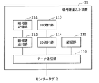
- FIG. 6 is a block diagram showing the configuration of the encryption key writing device 11. As illustrated in FIG. 6, the encryption key writing device 11 includes a data communication unit 110, an encryption key storage unit 111, an encryption key sending unit 112, an ID receiving unit 113, an ID sending unit 114, and an authentication unit 115.
- the data communication unit 110 performs data transmission / reception with the sensor tag 2.
- the encryption key storage unit 111 stores an encryption key set by the administrator of the encryption key writing device 11.
- the encryption key sending unit 112 reads the encryption key stored in the encryption key storage unit 111 and sends it to the sensor tag 2 via the data communication unit 110.
- the ID receiving unit 113 receives ID data input from the outside of the encryption key writing device 11 and outputs the received ID data to the ID sending unit 114.
- the ID sending unit 114 sends the ID data output from the ID receiving unit 113 to the sensor tag 2 via the data communication unit 110.
- the authentication unit 115 performs an authentication process for proving the validity of the encryption key writing device 11 for the sensor tag 2 using the authentication data stored inside.
- FIG. 7 is a block diagram illustrating a configuration of the measurement data reading device 13. As shown in FIG. 7, the measurement data reading device 13 includes a data communication unit 130, an authentication unit 131, a decryption key storage unit 135, a measurement data reading unit 132, a data decryption unit 133, and a measurement data storage unit 134.
- the data communication unit 130 performs data transmission / reception with the sensor tag 2.
- the authentication unit 131 performs an authentication process for proving the validity of the measurement data reading device 13 for the sensor tag 2 using the authentication data stored inside.
- the decryption key storage unit 135 stores a decryption key set by the administrator of the measurement data reader 13.
- the measurement data reading unit 132 receives the encrypted measurement data from the sensor tag 2 via the data communication unit 130 and outputs it to the data decryption unit 133.
- the data decryption unit 133 uses the decryption key read from the decryption key storage unit 135 to decrypt the encrypted measurement data received from the measurement data reading unit 132, and calculates plaintext measurement data.
- the data decryption unit 133 outputs the calculated plaintext measurement data to the measurement data storage unit 134.
- the measurement data storage unit 134 stores the plaintext measurement data received from the data decryption unit 133.
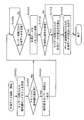
- FIG. 8 is a flowchart showing the overall operation of the sensor tag 2. In the figure, the flow of processing among the sensor circuit 22, the memory access control circuit 25, and the data communication circuit 20 is shown.
- the processing performed by the sensor tag 2 is roughly classified into three: key setting processing 3, measurement processing 4, and measurement data reading processing 5.
- key setting processing 3 is performed. That is, the data communication unit 110 of the encryption key writing device 11 transmits an activation signal to the antenna 21 of the sensor tag 2.
- the antenna 21 outputs the received start signal to the electromotive force generation circuit 30, and the electromotive force generation circuit 30 generates an electromotive force from the start signal, so that each circuit in the sensor tag 2 including the data communication circuit 20 is transmitted.
- Operate (S2) Hereinafter, the data communication circuit 20 performs processing while operating with the electromotive force generated by the activation signal appropriately received from the data communication unit 110 of the encryption key writing device 11.
- the data communication circuit 20 acquires an encryption key from the encryption key writing device 11 (S4).
- the memory access control circuit 25 sets the acquired encryption key in the memory 24 (S6).
- the encryption key is set in the memory 24 by the processing so far.
- the processes of S4 and S6 will be described later in detail.
- the measurement process 4 is started. That is, the power supply 23 is switched to the ON state, and the power supply state detection unit 225 detects the ON state of the power supply 23 (S8).
- the memory access control circuit 25 changes the memory access control rule (mode) (S10). That is, encryption key writing and ID writing to the memory 24 from the data communication circuit 20 are prohibited. After this mode change, the encryption key cannot be updated thereafter (S16, S18, S20). Therefore, it is possible to prevent the encryption key from being rewritten accidentally when the measurement data is encrypted.
- mode memory access control rule
- the sensor circuit 22 measures the biological information of the person 12 to be measured and outputs the measurement data to the memory access control circuit 25 (S12).
- the memory access control circuit 25 accumulates the output measurement data in the memory 24 (S14). Thereafter, the processes of S12 and S14 are repeatedly executed. The processing of S8 to S14 will be described in detail later.
- measurement data reading processing 5 is performed. That is, the data communication unit 130 of the measurement data reading device 13 transmits an activation signal to the antenna 21 of the sensor tag 2.
- the antenna 21 outputs the received start signal to the electromotive force generation circuit 30, and the electromotive force generation circuit 30 generates an electromotive force from the start signal, so that each circuit in the sensor tag 2 including the data communication circuit 20 is transmitted.
- the data communication circuit 20 performs processing while operating with an electromotive force generated by an activation signal appropriately received from the data communication unit 130 of the measurement data reading device 13.
- the data communication circuit 20 outputs a measurement data acquisition request signal to the memory access control circuit 25 based on the measurement data acquisition request from the measurement data reader 13 (S24).
- the memory access control circuit 25 stops the measurement of biological information by the sensor circuit 22 (S26). Thereafter, the memory access control circuit 25 reads the measurement data stored in the memory 24 and outputs it to the data communication circuit 20 (S28).
- the data communication circuit 20 receives the measurement data from the memory access control circuit 25 and outputs it to the measurement data reading device 13 (S30). The processing of S24 to S30 will be described in detail later.
- the key setting process 3 is a process in which the encryption key writing device 11 sets an encryption key for the sensor tag 2 for which no encryption key is set.
- the encryption key writing device 11 is held and managed by the hospital, and the key setting process 3 is performed when the hospital purchases the sensor tag 2 for which the encryption key is not set.
- the encryption key storage unit 111 stores an encryption key preset by an administrator of the encryption key writing device 11.
- the authentication unit 115 stores password data having a predetermined number of digits.
- the authentication unit 201 in the data communication circuit 20 of the sensor tag 2 stores a hash value, which is a result of calculating a hash function for the password data, as authentication verification data.
- the memory access control circuit 25 of the sensor tag 2 is set with a memory access control rule that permits only the following memory access and denies other memory access.
- FIG. 9 is a detailed flowchart of the encryption key acquisition process (S4).
- the authentication unit 115 of the encryption key writing device 11 sends password data, which is stored authentication data, to the sensor tag 2 via the data communication unit 110.
- the antenna 21 of the sensor tag 2 receives the authentication data and transfers it to the authentication unit 201 via the data communication unit 200 of the data communication circuit 20.
- the authentication unit 201 calculates a hash value that is a result of calculating a hash function for the received authentication data.
- the authentication unit 201 compares the calculated hash value with the authentication verification data stored therein, and if the two match, the authentication unit 201 validates the encryption key writing device 11 and performs subsequent key setting processing. Allow to do. If they do not match, it is assumed that the encryption key writing device 11 is not valid, and the subsequent key setting process is stopped (S402).
- the operator of the encryption key writing device 11 inputs the ID to be set to the sensor tag 2 to the encryption key writing device 11.
- the input ID is received by the ID receiving unit 113 and transferred to the data communication unit 110 via the ID sending unit 114.
- the encryption key sending unit 112 reads the encryption key stored in the encryption key storage unit 111 and transfers it to the data communication unit 110.
- the data communication unit 110 transmits the ID and encryption key to the sensor tag 2.
- the antenna 21 of the sensor tag 2 receives the ID and the encryption key transmitted from the encryption key writing device 11.
- the antenna 21 transfers the received ID and encryption key to the data communication unit 200 of the data communication circuit 20.
- the data communication unit 200 transfers the ID to the ID writing unit 203, and transfers the encryption key to the encryption key writing unit 202 (S404).
- the ID writing unit 203 transfers the received ID to the memory access control circuit 25 (S406).
- the encryption key writing unit 202 transfers the received encryption key to the memory access control circuit 25 (S408).
- FIG. 10 is a detailed flowchart of the encryption key setting process (S6).
- the memory access control circuit 25 receives the ID from the ID writing unit 203 and the encryption key from the encryption key writing unit 202 (S602).
- the memory access control circuit 25 checks the memory access control rules set inside, and confirms that ID writing from the data communication circuit 20 and encryption key writing from the data communication circuit 20 are permitted. (Yes in S604) The ID is written in the ID storage area of the memory 24, and the encryption key is written in the encryption key storage area of the memory 24 (S606).
- the key setting process 3 is completed by the above series of processes (S4, S6).
- the measurement process 4 is a process in which the sensor tag 2 with the encryption key set periodically measures the biological information of the person 12 to be measured.
- the measurement is performed when a measurement subject 12 who is a patient who has been provided with a sensor tag 2 with an encryption key set from a hospital performs measurement of biological information by attaching the sensor tag 2 to the body at home or the like. Is called.
- FIG. 11 is a detailed flowchart of the power ON detection process (S8).
- the power supply state detection unit 225 confirms the state of power supply from the power supply 23 (S802).
- the person to be measured 12 removes the insulator 27 from the sensor tag 2 at the start of measurement.
- power is supplied to the sensor circuit 22 from the power source 23, and the sensor circuit 22 starts to operate.
- the sensor circuit 22 performs processing while operating with electric power supplied from the power source 23.
- the power supply state detection unit 225 sends the memory access control circuit 25 to the memory 24 from the data communication circuit 20.
- the encryption key write disable signal for instructing prohibition of the encryption key writing and ID writing is output (S806).
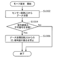
- FIG. 12 is a detailed flowchart of the mode change process (S10).
- the memory access control circuit 25 receives data from the sensor circuit 22 (S1002).
- the data received by the memory access control circuit 25 is an encryption key write disable signal (Yes in S1004)
- the memory access control rule update unit 26 performs the encryption key write from the data communication circuit 20 to the memory 24.
- the memory access control rule (mode) is changed so as to prohibit the ID writing (S1006). That is, the memory access control rule update unit 26 updates the memory access control rule set in the memory access control circuit 25 so that only the following memory access is permitted and other memory accesses are denied.
- FIG. 13 is a detailed flowchart of the sensor measurement process (S12).
- the biological data measurement unit 220 measures biological information from the measurement subject 12. Data obtained by adding the count value transferred from the timer unit 221 to the measured biometric information (hereinafter referred to as “measurement data”) is transferred to the data encryption unit 223 (S1202).
- the encryption key reading unit 222 requests an encryption key from the memory access control circuit 25 (S1204).
- the encryption key reading unit 222 acquires the encryption key from the memory access control circuit 25 (Yes in S1206)
- the data encryption unit 223 receives the encryption key from the encryption key reading unit 222 and uses the encryption key. Then, the measurement data received from the biometric data measurement unit 220 is encrypted to generate encrypted measurement data (S1208).
- the count value is not encrypted, but may be encrypted.
- the data encryption unit 223 adds the count value received from the biometric data measurement unit 220 to the encrypted measurement data and transfers it to the measurement data writing unit 224.
- the measurement data writing unit 224 transfers the encrypted measurement data and the count value received from the data encryption unit 223 to the memory access control circuit 25 and makes a write request to the memory 24 (S1210).
- the data encryption unit 223 encrypts the measurement data into the biometric data without encrypting the measurement data.
- the count value received from the data measurement unit 220 is added and transferred to the measurement data writing unit 224.
- the measurement data writing unit 224 transfers the unencrypted measurement data and the count value received from the data encryption unit 223 to the memory access control circuit 25 and makes a write request to the memory 24 (S1210).
- FIG. 14 is a detailed flowchart of the measurement data accumulation process (S14).
- the memory access control circuit 25 receives an encryption key request from the sensor circuit 22 (S1402).
- the memory access control circuit 25 checks the memory access control rules held therein to confirm that the encryption key reading from the sensor circuit 22 is permitted. If the above can be confirmed, the memory access control circuit 25 confirms whether or not an encryption key is set in the memory 24 (S1404).
- the memory access control circuit 25 reads the encryption key from the encryption key storage area of the memory 24 and transfers it to the encryption key reading unit 222 of the sensor circuit 22 (S1406). .
- the memory access control circuit 25 waits until it receives the encrypted measurement data and the count value from the measurement data writing unit 224 of the sensor circuit 22 (S1408).
- the memory access control circuit 25 checks the memory access control rule held inside, and writing of the encrypted measurement data from the sensor circuit 22 is permitted. Make sure. If the above can be confirmed, the memory access control circuit 25 writes the encrypted measurement data and the count value received from the measurement data writing unit 224 of the sensor circuit 22 in the encrypted measurement data storage area of the memory 24 (S1410). . If the encryption key is not set in the memory 24 (No in S1404), the same processing (S1408, S1410) is performed on the unencrypted measurement data.
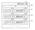
- the encrypted measurement data group 6 includes one ID 60, one or more sets of timer data (timer data 610, 620, 630,...) And encrypted measurement data (encrypted measurement data 611, 621, 631,. ..)) And a data set (data sets 61, 62, 63,).
- ID 60 is the ID set in the sensor tag 2 together with the encryption key in the key setting process 3.
- the timer data and the encrypted measurement data are added one by one every time the measurement data storage process is executed.
- the measurement data reading process 5 is a process in which the measurement data reading device 13 reads the encrypted measurement data from the sensor tag 2 that has been subjected to the measurement process, as shown on the right side of FIG. As a typical example, this is performed in a hospital when the measurement data reading device 13 is used to read the encrypted measurement data from the sensor tag 2 that has been subjected to the measurement process and is submitted from the measurement subject 12 as a patient.
- the decryption key storage unit 135 stores a decryption key preset by the administrator of the measurement data reading device 13.
- the decryption key is paired with the encryption key stored in the encryption key storage unit 111 of the encryption key writing device 11. That is, original data can be obtained by decrypting encrypted data obtained by encrypting certain data with an encryption key with a decryption key.
- the authentication unit 131 stores the same password data stored in the authentication unit 115 of the encryption key writing device 11.
- the encrypted measurement data group 6 as shown in FIG. 15 is stored in the memory 24 of the sensor tag 2.
- FIG. 16 is a detailed flowchart of the data acquisition request process (S24).
- the authentication unit 131 of the measurement data reading device 13 sends password data that is stored authentication data to the sensor tag 2 via the data communication unit 130.
- the antenna 21 of the sensor tag 2 receives the authentication data and transfers it to the authentication unit 201 via the data communication unit 200 of the data communication circuit 20.
- the authentication unit 201 calculates a hash value that is a result of calculating a hash function for the received authentication data.
- the authentication unit 201 compares the calculated hash value with the authentication verification data stored therein, and if they match, makes the measurement data reading device 13 valid and performs the subsequent measurement data reading process. Admit. If they do not match, it is assumed that the measurement data reading device 13 is not valid, and the subsequent measurement data reading process is stopped (S2402).
- the measurement data reading unit 132 transmits a measurement data acquisition request signal to the sensor tag 2 via the data communication unit 130.
- the antenna 21 of the sensor tag 2 receives the measurement data acquisition request signal transmitted from the measurement data reader 13.
- the antenna 21 transfers the received measurement data acquisition request signal to the data communication unit 200 of the data communication circuit 20.
- the data communication unit 200 transfers the measurement data acquisition request signal to the measurement data reading unit 204 (S2404).
- the measurement data reading unit 204 transmits a measurement data acquisition request signal to the memory access control circuit 25 (S2406).
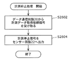
- FIG. 17 is a detailed flowchart of the measurement stop process (S26).
- the memory access control circuit 25 When the memory access control circuit 25 receives the measurement data acquisition request signal from the measurement data reading unit 204 of the data communication circuit 20 (S2602), it outputs a measurement stop signal to the sensor circuit 22 (S2604). At the same time, the memory access control rule update unit 26 sets the memory access control rule (mode) set in the memory access control circuit 25 so as to prohibit the writing of the encrypted measurement data from the sensor circuit 22 to the memory 24. ). Thus, since the encrypted measurement data is not written to the memory 24 by the sensor circuit 22 during transmission of the encrypted measurement data by the data communication circuit 20, the encrypted encrypted measurement stored in the memory 24 is not performed. Data transmission leakage can be prevented.
- the sensor circuit 22 that has received the measurement stop signal stops the subsequent measurement of biological information.
- the memory access control circuit 25 may not store the encrypted measurement data in the memory 24 instead of the sensor circuit 22 stopping the measurement.
- FIG. 18 is a detailed flowchart of the data acquisition process (S28).
- the memory access control circuit 25 checks the memory access control rule set inside, and confirms that reading of the encrypted measurement data from the data communication circuit 20 is permitted. If the above confirmation can be made, the memory access control circuit 25 reads the encrypted measurement data group 6 from the memory 24 (S2802) and transfers it to the measurement data reading unit 204 (S2804).
- FIG. 19 is a detailed flowchart of the data output process (S30).
- the measurement data reading unit 204 receives the encrypted measurement data group 6 transferred from the memory access control circuit 25 (S3002).
- the measurement data reading unit 204 transmits the received encrypted measurement data group 6 to the measurement data reading device 13 via the data communication unit 200 and the antenna 21 (S3004).
- the encrypted measurement data group 6 is transferred to the data decryption unit 133 via the data communication unit 130 and the measurement data reading unit 132 of the measurement data reading device 13.
- the data decryption unit 133 decrypts the encrypted measurement data 611, 621, 631 of the received encrypted measurement data group 6 using the decryption key read from the decryption key storage unit 135, and obtains the plaintext measurement data thereof.
- the data obtained by replacing the encrypted measurement data 611, 621, and 631 in the encrypted measurement data group 6 with the plaintext measurement data is transferred to the measurement data storage unit 134 as a measurement data group.
- the measurement data storage unit 134 stores the received plaintext measurement data group.
- the measurement data reading process 5 is completed by the series of processes (S24 to S30).
- the measurement data storage unit 134 stores a measurement data group including one ID, one or more sets of timer data, and plaintext measurement data.
- the ID to be set may be determined according to the operation mode of the administrator who manages the encryption key writing device 11 and the measurement data reading device 13. For example, in order to identify a sensor tag, it may be a sensor tag ID, or may be a measured person ID that identifies a patient (measured person) to whom the sensor tag is passed. In the former operation, the ID to be set differs for each sensor tag, but in the latter operation, the same ID (patient ID) is set for all sensor tags to be passed to a patient.
- the timer data paired with each measurement data is used as time information when the measurement data is measured.
- the measurement data group stored in the measurement data storage unit 134 is read out as necessary, and is used for health management, health checkup, and the like of the patient 12 as a patient.
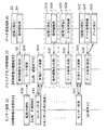
- FIG. 20 is a diagram for explaining the transition of the memory access control rule (mode) held by the memory access control circuit 25.
- the power supply from the power source 23 is in an OFF state, and no measurement is performed. Also, the encryption key is not set in the memory 24, and the encryption key writing from the data communication circuit 20 is permitted according to the memory access control rule.
- the process proceeds to a state (S4009) in which the measurement data subjected to the encryption process is stored (S4009), and the measurement process ends. That state is maintained until.
- the measurement stop process (S26) is executed, and then the process proceeds to a state where the measurement of biological information is stopped (S4007). Thereafter, the acquisition process (S24) is executed, and a series of processes ends.
- the data communication circuit that performs the encryption key setting process is operated by the electric power generated from the activation signal received from the encryption key writing device 11.
- the power supply from the built-in battery is turned off when setting the encryption key, even in the case of a small sensor tag that cannot be mounted with a switch mechanism that can freely switch on and off the power supply from the power source 23. Since there is no need to turn it ON, the problem of battery consumption until the start of measurement described as a problem does not occur.
- the encryption key can be received wirelessly, the encryption key can be set in the sensor tag 2 without breaking the sterilized package. Therefore, a hygienic state can be maintained until immediately before the sensor tag 2 is used.
- the memory access control rule update unit 26 updates the memory access control rule of the memory access control circuit 25 so that the encryption key cannot be written. . Thereby, after power is supplied from the power source 23 to the sensor circuit 22 and measurement is started, an erroneous operation that erroneously rewrites the encryption key can be prevented.
- a measurement stop process (S26) described below may be executed.
- FIG. 21 is a detailed flowchart of the measurement stop process (S26) according to the first modification of the first embodiment.
- the memory access control circuit 25 When the memory access control circuit 25 receives the measurement data acquisition request signal from the measurement data reading unit 204 of the data communication circuit 20 (S2602), the encryption from the sensor circuit 22 to the memory 24 within the past predetermined period with reference to the present. It is determined whether or not there has been a write processing of the measurement data (S2612).
- the memory access control rule update unit 26 transmits data from the sensor circuit 22 to the memory 24.
- the memory access control rule (mode) set in the memory access control circuit 25 is changed so as to permit writing of the encrypted measurement data (S2614).
- the memory access control rule update unit 26 transfers the data from the sensor circuit 22 to the memory 24.
- the memory access control rule (mode) set in the memory access control circuit 25 is changed so as to prohibit the writing of the encrypted measurement data (S2616).
- the memory access control circuit 25 After the processing of S2616, the memory access control circuit 25 outputs a measurement stop signal to the sensor circuit 22 (S2604).
- the memory access control circuit 25 considers that the power of the power supply 23 is consumed when there is no writing from the sensor circuit 22 to the memory 24 for a predetermined period, and the sensor circuit 22 Data writing to the memory 24 is prohibited. Thereby, when the encrypted measurement data to be transmitted to the data communication circuit 20 is sufficiently stored in the memory 24, the data communication circuit 20 can read the encrypted measurement data from the memory 24 and transmit it to a predetermined destination. Therefore, for example, when the acquisition request from the data communication circuit 20 is received immediately after the power supply from the power supply 23 is turned on, the encrypted measurement data to be transmitted to the data communication circuit 20 is stored in the memory 24. It is possible to prevent the inefficiency that the encrypted measurement data is transmitted from the memory 24 in a state where it is not sufficiently stored with a simple configuration.
- the memory access control circuit 25 determines that the life of the power of the power supply 23 still exists when the writing from the encryption circuit to the memory 24 exists within a predetermined period, and the data from the sensor circuit 22 to the memory 24 Is maintained, and a state in which data writing from the data communication circuit 20 to the memory 24 is prohibited is maintained. As a result, when it is determined that the power life of the power source 23 is still present, even if a request for acquisition of encrypted measurement data stored in the memory 24 is received from the data communication circuit 20, the memory 24 stores The process of storing the encrypted measurement data to be transmitted to the data communication circuit 20 is continued.
- the encrypted measurement data to be transmitted to the data communication circuit 20 is stored in the memory 24. It is possible to prevent the inefficiency that the encrypted measurement data is transmitted from the memory 24 in a state where it is not sufficiently stored with a simple configuration.
- a measurement stop process (S26) described below may be executed.
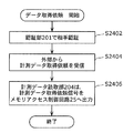
- FIG. 22 is a detailed flowchart of the measurement stop process (S26) according to the second modification of the first embodiment.
- the memory access control circuit 25 When the memory access control circuit 25 receives a measurement data acquisition request signal from the measurement data reading unit 204 of the data communication circuit 20 (S2602), the memory access control circuit 25 detects an operation confirmation signal for confirming that the sensor circuit 22 is in an operation state. The data is output to the circuit 22 (S2622). It is assumed that the sensor circuit 22 in the operating state outputs a response signal to the memory access control circuit 25 when receiving the operation confirmation signal.
- the memory access control circuit 25 determines whether or not a response signal has been received from the sensor circuit 22 within a predetermined period (S2624).
- the memory access control rule update unit 26 allows the memory access control circuit 25 to permit the writing of the encrypted measurement data from the sensor circuit 22 to the memory 24.
- the memory access control rule (mode) set inside is changed (S2614).
- the memory access control rule update unit 26 prohibits the writing of the encrypted measurement data from the sensor circuit 22 to the memory 24.
- the memory access control rule (mode) set in 25 is changed (S2616).
- the memory access control circuit 25 After the processing of S2616, the memory access control circuit 25 outputs a measurement stop signal to the sensor circuit 22 (S2604).
- the memory access control circuit 25 considers that the power of the power supply 23 has been consumed when the response from the sensor circuit 22 is not within a predetermined period, and the sensor circuit 22 Writing data to the memory 24 is prohibited. Thereby, when the encrypted measurement data to be transmitted to the data communication circuit 20 is sufficiently stored in the memory 24, the data communication circuit 20 can read the encrypted measurement data from the memory 24 and transmit it to a predetermined destination. Therefore, for example, when the acquisition request from the data communication circuit 20 is received immediately after the power supply from the power supply 23 is turned on, the encrypted measurement data to be transmitted to the data communication circuit 20 is stored in the memory 24. It is possible to prevent the inefficiency that the encrypted measurement data is transmitted from the memory 24 in a state where it is not sufficiently stored with a simple configuration.
- the memory access control circuit 25 determines that the power of the power source 23 is still present, and writes the data from the sensor circuit 22 to the memory 24. The state of permitting and prohibiting the writing of data from the data communication circuit 20 to the memory 24 is maintained. As a result, if it is determined that the power supply 23 still has a life, the memory 24 stores the encrypted measurement data stored in the memory 24 from the data communication circuit 20 even when it receives an acquisition request. Then, the process of storing the encrypted measurement data to be transmitted to the data communication circuit 20 is continued.
- the encrypted measurement data to be transmitted to the data communication circuit 20 is stored in the memory 24. It is possible to prevent the inefficiency that the encrypted measurement data is transmitted from the memory 24 in a state where it is not sufficiently stored with a simple configuration.
- the sensor circuit 22 may discard the measurement data and not transfer it to the memory access control circuit 25.
- FIG. 23 is a detailed flowchart of the sensor measurement process (S12) according to the third modification of the first embodiment.
- Each process is the same as that shown in FIG. 7, but as described above, when the encryption key reading unit 222 cannot acquire the encryption key (No in S1208), the sensor circuit 22 performs nothing. Do not execute processing. As a result, the measurement data is not discarded and transmitted to the memory access control circuit 25.
- measurement of biological information by the sensor circuit 22 ends when a measurement data acquisition request is made from the measurement data reader 13 to the sensor tag 2.
- the measurement of the biological information by the sensor circuit 22 ends when the sensor circuit 22 measures the biological information a predetermined number of times or for a predetermined time.
- the configurations of the sensor tag system 1, the sensor tag 2, the encryption key writing device 11, and the measurement data reading device 13 constituting the sensor tag system 1 are the same as those described in the first embodiment. Therefore, detailed description thereof will not be repeated here.
- the measurement process 4 executed by the sensor circuit 22 is partly different from the first embodiment.
- the description will focus on the different points.
- FIG. 24 is a flowchart showing the entire operation of the sensor tag 2. In the same figure, similarly to FIG. 8, the flow of processing among the sensor circuit 22, the memory access control circuit 25, and the data communication circuit 20 is shown.
- the key setting process 3 (S2 to S6) is the same as that shown in the first embodiment. Therefore, detailed description thereof will not be repeated here.
- the measurement process 4 is started. That is, the power supply from the power supply 23 is switched to the ON state, and the power supply state detection unit 225 detects the ON state of the power supply from the power supply 23 (S38).
- the memory access control circuit 25 changes the memory access control rule (mode) (S40). That is, encryption key writing and ID writing to the memory 24 from the data communication circuit 20 are prohibited. Further, reading of the encrypted measurement data from the data communication circuit 20 is also prohibited. After this mode change, the encryption key cannot be updated thereafter (S16, S18, S20). Further, it becomes impossible to acquire the encrypted measurement data (S22, S24, S28).
- the sensor circuit 22 measures the biological information of the person 12 to be measured and outputs the measurement data to the memory access control circuit 25 (S42).
- the memory access control circuit 25 accumulates the output measurement data in the memory 24 (S44). Thereafter, the processes of S42 and S14 are repeatedly executed a predetermined number of times. Thereby, the measurement data for a predetermined number of times is accumulated in the memory 24.
- the processing of S42 and S44 will be described in detail later.
- the sensor measurement process (S42) ends.
- reading of the encrypted measurement data from the data communication circuit 20 is permitted, and the measurement data reading process 5 (S22 to S30) is performed.
- the power supply state detection unit 225 transmits data to the memory access control circuit 25.
- a measurement data read disable signal instructing prohibition of reading of the encrypted measurement data from the memory 24 by the communication circuit 20 is output (S812).
- the memory access control circuit 25 determines whether or not a measurement data read disable signal has been received (S1012).
- the memory access control rule update unit 26 controls the memory access so as to prohibit the data communication circuit 20 from reading the encrypted measurement data from the memory 24.
- the rule (mode) is changed (S1014). That is, the memory access control rule update unit 26 updates the memory access control rule set in the memory access control circuit 25 so that only the following memory access is permitted and other memory accesses are denied.
- the biological data measurement unit 220 increments the number of measurements stored therein by one (S1212). Note that the number of times of measurement is set to 0 in advance at the start of measurement.
- the biological data measurement unit 220 determines whether or not the current measurement count exceeds a predetermined threshold (S1214). When it is determined that the threshold value is exceeded (Yes in S1214), the biometric data measurement unit 220 stops measuring biometric information (S1216). Further, the measurement data writing unit 224 outputs a measurement stop signal indicating that the measurement of the biological information is stopped to the memory access control circuit 25 (S1218). Thereby, after measurement of biological information is performed a predetermined number of times, measurement of biological information ends.
- the memory access control circuit 25 may not store the encrypted measurement data in the memory 24 instead of the sensor circuit 22 stopping the measurement.
- S1410 it is determined whether or not the memory access control circuit 25 has received a measurement stop signal (S1412). If it is determined that the measurement stop signal has been received (Yes in S1412), the memory access control rule update unit 26 prohibits writing of the encrypted measurement data from the sensor circuit and performs the encrypted measurement from the data communication circuit 20.
- the memory access control rule (mode) is changed so as to permit data reading (S1413, S1414). That is, the memory access control rule update unit 26 updates the memory access control rule set in the memory access control circuit 25 so that only the following memory access is permitted and other memory accesses are denied.
- the measurement of biological information is stopped when the number of measurements exceeds a predetermined threshold.
- the stop condition is not limited to this.
- the biological data measuring unit 220 of the sensor circuit 22 may be configured to monitor the timer data (count value) of the timer unit 221 and stop measuring biological information when the count value exceeds a predetermined threshold.
- the timer unit 221 manages the time from the start of measurement
- the biometric data measurement unit 220 monitors the time from the start of measurement, and stops measuring biometric information when the time exceeds a predetermined threshold. It is also good.
- the second embodiment has the same effects as the first embodiment.
- the sensor circuit 22 does not write to the memory 24. For this reason, it is possible to prevent leakage of reading of the encrypted measurement data stored in the memory 24.
- the encryption method used for encryption and decryption is not limited to a specific algorithm.
- Public key cryptosystems such as RSA (Rivest Shamir Adleman) cryptosystem, elliptic curve cryptosystem, and ElGamal cryptosystem may be used, and common key cryptography such as AES (Advanced Encryption Standard) cryptography and DES (Data Encryption Standard) cryptography. It may be a method.
- the data size and the number of data of each data are not limited to a specific size and number.
- the encryption target is not limited to the data described in the above embodiment.
- counter information indicating what number the measurement data is after the measurement is started is recorded together with the measurement data, and the counter information may also be encrypted.
- the data written to the sensor tag 2 is not limited to the measurement data by the sensor tag 2.
- personal information such as a patient's name, address, and telephone number may be written. In that case, you may encrypt with the set key.
- the sensor tag 2 may include two or more types of sensor circuits. That is, the sensor tag 2 may measure and accumulate two or more types of measurement data. In that case, a sensor type ID for identifying the type of measurement data may be added and stored together with the measurement data. Further, depending on the type of measurement data, it may be set to be encrypted and saved or not encrypted. Furthermore, a rule for determining whether to encrypt the measurement data from the type of the measurement data may be set from the outside. The rule setting process may be performed at the time of key setting, or may be changed by an instruction from the outside during the measurement.
- the number of encryption keys that can be set in the sensor tag 2 is one, but a plurality of encryption keys may be set in the sensor tag 2.
- an encryption key used for encryption of the measurement data may be set depending on the type of measurement data, or the encryption key may be changed depending on the time and place where the measurement data is measured.
- the rules for determining the encryption key to be used as described above may have a mechanism that can be acquired inside the sensor tag 2, or may be acquired from outside the sensor tag 2.
- the method in which the sensor tag 2 authenticates the validity of the encryption key writing device 11 and the measurement data reading device 13 is not limited to the method using the hash value shown in the above embodiment. Alternatively, challenge-response authentication using a common key cryptosystem or a public key cryptosystem may be used. Communication data between the sensor tag 2 and the encryption key writing device 11 or the measurement data reading device 13 may be encrypted using SSL (Secure Socket Layer) or the like. Furthermore, there are a plurality of authentication methods for the sensor tag 2 to authenticate the measurement data reading device 13 during the measurement data reading process, and the measurement data reading device 13 acquires from the sensor tag 2 depending on the type of authentication method used. The information that can be changed. Further, when there are a plurality of measurement data reading devices, the information provided by the sensor tag 2 may be changed for each device.
- SSL Secure Socket Layer
- the sensor tag 2 measures the biological information by the biological data measurement unit 220 in the sensor circuit 22, but the measurement function of the biological information may be performed by a device other than the sensor tag 2.
- the biological information measuring device there is a biological information measuring device other than the sensor tag 2, and the biological information measuring device transmits the measured biological data to the sensor tag 2 by wireless communication or the like.
- the receiving circuit 28 of the sensor tag 2 receives the transmitted biological data.
- the sensor tag 2 can be used as the sensor tag 2 that is separate from the biological information measuring device.
- the hospital manages the encryption key writing device 11 and the measurement data reading device 13 and provides the patient with the sensor tag 2 after setting the encryption key.
- the encryption key writing device 11 and the measurement data reading device 13 may be managed by the patient, and the encryption key uniquely determined by the patient may be set in the sensor tag 2.
- the encryption key writing device 11 and the measurement data reading device 13 may be connected to a server via a network. At this time, the encryption key and the decryption key are held by the server. When the encryption key is set in the sensor tag 2 or when the encrypted measurement data is read from the measured sensor tag 2 and decrypted, the encryption key is written. The apparatus 11 and the measurement data reading apparatus 13 may acquire an encryption key and a decryption key from the server.
- the sensor tag 2 may not only encrypt the measurement data but also generate falsification detection data of the measurement data.
- a method for generating falsification detection data a MAC (Message Authentication Code) generation method using a known encryption key may be used.
- the sensor tag system 1 is not limited to the use case of measuring biological information. For example, it can be used for environmental management of fresh foods during transportation.
- the sensor tag 2 is installed in a fresh food product or a container that transports it, and measures and accumulates temperature, humidity, illuminance, and the like during transportation.
- the sensor circuit 22 may be an acceleration sensor or a GPS (Global Positioning System) receiving module, and the sensor tag system 1 may be used as an action tracking system that measures a position history and a moving speed. In this case, the position history and movement speed of the measurement subject wearing the sensor tag 2 can be encrypted and recorded in the sensor tag 2.
- the present invention is not limited to a tag with a sensor function, and may be an authentication tag that performs challenge-response authentication using a set encryption key, for example. That is, the present invention can be applied to any cryptographic processing apparatus that performs cryptographic processing inside the apparatus and can set an encryption key used for the cryptographic processing from the outside.
- the method is performed by removing the attached insulator 27, but the method is not limited thereto.
- the power supply from the power supply 23 to the sensor circuit 22 may be switched from OFF to ON by a mechanism such as a magnetic switch or an infrared switch.
- the measurement data reader 13 uses non-contact wireless communication via the antenna 21 as a communication method for reading measurement data from the sensor tag 2, it is not limited to this and is not limited to this. May be used.
- the power supply at the time of data reading is not limited to the activation signal from the measurement data reading device 13 and may be supplied from the power supply 23 built in the sensor tag 2.
- the encryption key writing device 11 may hold the encryption key to be set for the sensor tag 2 inside the encryption key writing device 11 or from the outside of the device. It may be input. Further, the encryption key writing device 11 may be connected to the encryption key management device during the encryption key setting process via the network, received from the encryption key management device, and set to the sensor tag 2.
- the measurement data reading device 13 may be connected to the sensor tag 2 via a network such as the Internet and read the encrypted measurement data group.
- the method of updating the memory access control rule of the memory access control circuit 25 when power is supplied from the power supply 23 to the sensor circuit 22 is not limited to the method described in the above embodiment.
- the signal line for writing the encryption key may be cut so that the encryption key cannot be written physically.
- each of the above devices is a computer system including a microprocessor, ROM, RAM, a hard disk unit, a display unit, a keyboard, a mouse, and the like.
- a computer program is stored in the RAM or hard disk unit.
- Each device achieves its functions by the microprocessor operating according to the computer program.
- the computer program is configured by combining a plurality of instruction codes indicating instructions for the computer in order to achieve a predetermined function.
- a part or all of the components constituting each of the above devices may be configured by one system LSI (Large Scale Integration).
- the system LSI is an ultra-multifunctional LSI manufactured by integrating a plurality of components on a single chip, and specifically, a computer system including a microprocessor, ROM, RAM, and the like. .
- a computer program is stored in the RAM.
- the system LSI achieves its functions by the microprocessor operating according to the computer program.
- a part or all of the constituent elements constituting each of the above devices may be constituted by an IC card or a single module that can be attached to and detached from each device.
- the IC card or the module is a computer system including a microprocessor, a ROM, a RAM, and the like.
- the IC card or the module may include the super multifunctional LSI described above.
- the IC card or the module achieves its function by the microprocessor operating according to the computer program. This IC card or this module may have tamper resistance.
- the present invention may be the method described above. Further, the present invention may be a computer program that realizes these methods by a computer, or may be a digital signal composed of the computer program.
- the present invention also provides a computer-readable recording medium such as a flexible disk, hard disk, CD-ROM, MO, DVD, DVD-ROM, DVD-RAM, BD (Blu-ray Disc). ), Recorded in a semiconductor memory or the like.
- the digital signal may be recorded on these recording media.
- the computer program or the digital signal may be transmitted via an electric communication line, a wireless or wired communication line, a network represented by the Internet, a data broadcast, or the like.
- the present invention may be a computer system including a microprocessor and a memory, the memory storing the computer program, and the microprocessor operating according to the computer program.
- the program or the digital signal is recorded on the recording medium and transferred, or the program or the digital signal is transferred via the network or the like, and executed by another independent computer system. It is good.
- the sensor tag according to the present invention is characterized in that the encryption key can be set without wasting the built-in battery even when the ON / OFF mechanism for freely supplying power from the built-in battery cannot be mounted. Therefore, it is useful for realizing a sensor tag that requires encryption of sensor information stored under severe restrictions on battery capacity and mounting size.
Landscapes
- Engineering & Computer Science (AREA)
- Computer Security & Cryptography (AREA)
- Computer Networks & Wireless Communication (AREA)
- Signal Processing (AREA)
- Measuring And Recording Apparatus For Diagnosis (AREA)
- Storage Device Security (AREA)
- Mobile Radio Communication Systems (AREA)
Abstract
Description
2 センサータグ
3 鍵設定処理
4 計測処理
5 計測データ読取処理
6 暗号化計測データ群
11 暗号鍵書込み装置
12 被計測者
13 計測データ読取装置
20 データ通信回路
21 アンテナ
22 センサー回路
23 電源
24 メモリ
25 メモリアクセス制御回路
26 メモリアクセス制御規則更新部
27 絶縁体
28 受信回路
29 表示部
30 起電力発生回路
110、130、200 データ通信部
111 暗号鍵記憶部
112 暗号鍵送付部
113 ID受付部
114 ID送付部
115、131、201 認証部
132、204 計測データ読取部
133 データ復号部
134 計測データ蓄積部
135 復号鍵保管部
202 暗号鍵書込み部
203 ID書込み部
220 生体データ計測部
221 タイマー部
222 暗号鍵読取部
223 データ暗号化部
224 計測データ書込み部
225 電源状態検知部 DESCRIPTION OF
以下、本発明の実施の形態1について、図面を参照しながら説明する。 (Embodiment 1)
図1は、センサータグシステム1の構成を示すブロック図である。 <Overview>
FIG. 1 is a block diagram showing a configuration of the
次に、センサータグシステム1の構成について説明する。 <Configuration>
Next, the configuration of the
図3は、センサータグ2の構成を示すブロック図である。図3に示す通り、センサータグ2は、データ通信回路20、アンテナ21、センサー回路22、電源23、メモリ24、メモリアクセス制御回路25、メモリアクセス制御規則更新部26、絶縁体27、受信回路28、表示部29、起電力発生回路30を含む。 1.
FIG. 3 is a block diagram showing the configuration of the
図4は、データ通信回路20の構成を示すブロック図である。図4に示す通り、データ通信回路20は、データ通信部200、認証部201、暗号鍵書込み部202、ID書込み部203、計測データ読取部204を含む。 1.1.
FIG. 4 is a block diagram showing a configuration of the
図5は、センサー回路22の構成を示すブロック図である。図5に示す通り、センサー回路22は、生体データ計測部220、タイマー部221、暗号鍵読取部222、データ暗号化部223、計測データ書込み部224、電源状態検知部225を含む。 1.2.
FIG. 5 is a block diagram showing a configuration of the
図6は、暗号鍵書込み装置11の構成を示すブロック図である。図6に示す通り、暗号鍵書込み装置11は、データ通信部110、暗号鍵記憶部111、暗号鍵送付部112、ID受付部113、ID送付部114、認証部115を含む。 2. Encryption
FIG. 6 is a block diagram showing the configuration of the encryption
図7は、計測データ読取装置13の構成を示すブロック図である。図7に示す通り、計測データ読取装置13は、データ通信部130、認証部131、復号鍵保管部135、計測データ読取部132、データ復号部133、計測データ蓄積部134を含む。 3.
FIG. 7 is a block diagram illustrating a configuration of the measurement
以下、センサータグ2が行う処理について図面を参照しながら説明する。 <Operation>
Hereinafter, processing performed by the
次に、鍵設定処理3の詳細について説明する。鍵設定処理3は、図1の左側に示すとおり、暗号鍵書込み装置11が、暗号鍵が未設定のセンサータグ2に、暗号鍵を設定する処理である。典型的には、暗号鍵書込み装置11は、病院が保持・管理し、鍵設定処理3は、病院が暗号鍵未設定のセンサータグ2を買い入れたときに行われる。 1. Key setting process 3 (S4, S6)
Next, details of the
図6の暗号鍵書込み装置11において、暗号鍵記憶部111には、当該暗号鍵書込み装置11の管理者が予め設定した暗号鍵が、保管されている。認証部115には、所定桁数のパスワードデータが格納されている。また、センサータグ2のデータ通信回路20内部にある認証部201には、前記パスワードデータに対してハッシュ関数を計算した結果であるハッシュ値が、認証検証用データとして保管されている。 [Data settings, etc.]
In the encryption
(2)データ通信回路20からのID書込み
(3)データ通信回路20からの暗号化計測データ読出し
(4)センサー回路22からの暗号鍵読出し
(5)センサー回路22からの暗号化計測データ書込み
鍵設定処理3を行う時点では、図3に示すセンサータグ2は、絶縁体27が装着された状態なので、センサー回路22は、電源23からの電力供給を受けておらず、動作していない。 (1) Write encryption key from data communication circuit 20 (2) Write ID from data communication circuit 20 (3) Read encrypted measurement data from data communication circuit 20 (4) Read encryption key from sensor circuit 22 (5) ) Writing encrypted measurement data from the
図9は、暗号鍵取得処理(S4)の詳細なフローチャートである。 [Encryption key acquisition process (S4)]
FIG. 9 is a detailed flowchart of the encryption key acquisition process (S4).
次に、暗号鍵設定処理(S6)について説明する。 [Encryption key setting process (S6)]
Next, the encryption key setting process (S6) will be described.
次に、計測処理4の詳細について説明する。計測処理4は、図1の中程に示すとおり、暗号鍵設定済みのセンサータグ2が、被計測者12の生体情報を定期的に計測する処理である。典型的には、病院から暗号鍵設定済みのセンサータグ2を提供された患者である被計測者12が、自宅などで、センサータグ2を体に装着して生体情報の計測を行うときに行われる。 2. Measurement process 4 (S8 to S14)
Next, details of the
図11は、電源ON検知処理(S8)の詳細なフローチャートである。 [Power ON detection process (S8)]
FIG. 11 is a detailed flowchart of the power ON detection process (S8).
図12は、モード変更処理(S10)の詳細なフローチャートである。 [Mode change processing (S10)]
FIG. 12 is a detailed flowchart of the mode change process (S10).
(4)センサー回路22からの暗号鍵読出し
(5)センサー回路22からの暗号化計測データ書込み
上述したように、このメモリアクセス制御規則の更新により、これ以降は、暗号鍵を更新することが不可能となる(図8のS16、S18、S20)。 (3) Reading encrypted measurement data from data communication circuit 20 (4) Reading encryption key from sensor circuit 22 (5) Writing encrypted measurement data from
図13は、センサー計測処理(S12)の詳細なフローチャートである。 [Sensor measurement process (S12)]
FIG. 13 is a detailed flowchart of the sensor measurement process (S12).
図14は、計測データ蓄積処理(S14)の詳細なフローチャートである。 [Measurement data storage process (S14)]
FIG. 14 is a detailed flowchart of the measurement data accumulation process (S14).
計測処理4では、定期的に被計測者12の生体情報が計測されて、逐次、メモリ24に追記される。計測処理4が終了後には、メモリ24には、暗号鍵以外に、図15に示すような暗号化計測データ群6が記憶されている。暗号化計測データ群6は、1個のID60と、1組以上のタイマーデータ(タイマーデータ610、620、630、・・・)と暗号化計測データ(暗号化計測データ611、621、631、・・・)からなるデータ組(データ組61、62、63、・・・)とからなる。ID60は、鍵設定処理3で、暗号鍵とともにセンサータグ2に設定されたIDである。タイマーデータと暗号化計測データは、計測処理4において、計測データ蓄積処理が実行される度に1組ずつ追記されていく。 [Data in the
In the
次に、計測データ読取処理5の詳細について説明する。計測データ読取処理5は、図1の右側に示すとおり、計測データ読取装置13が、計測処理済みのセンサータグ2から、暗号化計測データを読み出す処理である。典型的な例として、病院において、計測データ読取装置13を用いて、患者である被計測者12から提出された計測処理済みのセンサータグ2から暗号化計測データを読み出すときに行われる。 3. Measurement data reading process 5 (S24 to S30)
Next, details of the measurement
図7の計測データ読取装置13において、復号鍵保管部135には、当該計測データ読取装置13の管理者が予め設定した復号鍵が、保管されている。復号鍵は、暗号鍵書込み装置11の暗号鍵記憶部111に記憶されている暗号鍵と対をなすものである。即ち、あるデータを暗号鍵で暗号化した暗号化データを復号鍵で復号すると、元のデータが得られるようになっている。認証部131には、暗号鍵書込み装置11の認証部115に保管されているものと同じパスワードデータが格納されている。 [Data settings, etc.]
In the measurement
図16は、データ取得依頼処理(S24)の詳細なフローチャートである。 [Data acquisition request processing (S24)]
FIG. 16 is a detailed flowchart of the data acquisition request process (S24).
図17は、計測停止処理(S26)の詳細なフローチャートである。 [Measurement stop processing (S26)]
FIG. 17 is a detailed flowchart of the measurement stop process (S26).
図18は、データ取得処理(S28)の詳細なフローチャートである。 [Data acquisition process (S28)]
FIG. 18 is a detailed flowchart of the data acquisition process (S28).
図19は、データ出力処理(S30)の詳細なフローチャートである。 [Data Output Processing (S30)]
FIG. 19 is a detailed flowchart of the data output process (S30).
以上のように、本実施の形態のセンサータグ2では、暗号鍵の設定処理を行うデータ通信回路は、暗号鍵書込み装置11から受信する起動信号から生起される電力によって動作するので、暗号鍵設定時に、絶縁体27を除去して、内蔵の電源23から電力供給を受ける必要がない。このために、電源23からの電力供給のON、OFFを自由に切り替え可能なスイッチ機構が実装できない小型センサータグのような場合であっても、暗号鍵設定時に、内蔵電池からの電力供給をOFFからONにする必要がないので、課題として述べた、計測開始までの電池消耗課題は起こらない。 <Summary>
As described above, in the
実施の形態1の図17に示した計測停止処理(S26)の代わりに、以下に説明する計測停止処理(S26)を実行するようにしてもよい。 (
Instead of the measurement stop process (S26) shown in FIG. 17 of the first embodiment, a measurement stop process (S26) described below may be executed.
実施の形態1の図17に示した計測停止処理(S26)の代わりに、以下に説明する計測停止処理(S26)を実行するようにしてもよい。 (
Instead of the measurement stop process (S26) shown in FIG. 17 of the first embodiment, a measurement stop process (S26) described below may be executed.
実施の形態1の図13に示したセンサー計測処理(S12)では、暗号鍵読取部222が暗号鍵を取得できなかった場合には(図13のS1206)、センサー回路22は、計測データを暗号化することなくメモリアクセス制御回路25に転送していた。 (
In the sensor measurement process (S12) shown in FIG. 13 of the first embodiment, when the encryption
次に、本発明の実施の形態2について、図面を参照しながら説明する。実施の形態1では、センサー回路22による生体情報の計測は、計測データ読取装置13からセンサータグ2に対して計測データ取得依頼が行なわれた時点で終了する。これに対して、実施の形態2では、センサー回路22により、所定回数または所定時間、生体情報の計測が行なわれた時点で、センサー回路22による生体情報の計測が終了する。 (Embodiment 2)
Next,
以下、センサータグ2が行う処理について図面を参照しながら説明する。 <Operation>
Hereinafter, processing performed by the
次に、図25を参照して、電源ON検知処理(S38)について説明する。 [Power ON detection process (S38)]
Next, the power ON detection process (S38) will be described with reference to FIG.
図26を参照して、モード変更処理(S40)について説明する。 [Mode change processing (S40)]
The mode change process (S40) will be described with reference to FIG.
(5)センサー回路22からの暗号化計測データ書込み
上述したように、このメモリアクセス制御規則の更新により、これ以降は、暗号化計測データを取得することが不可能となる(S22、S24、S28)。 (4) Reading the encryption key from the sensor circuit 22 (5) Writing the encrypted measurement data from the
図27を参照して、センサー計測処理(S42)について説明する。 [Sensor measurement process (S42)]
The sensor measurement process (S42) will be described with reference to FIG.
図28を参照して、計測データ蓄積処理(S44)について説明する。 [Measurement data storage process (S44)]
The measurement data accumulation process (S44) will be described with reference to FIG.
(4)センサー回路22からの暗号鍵読出し
これにより、生体情報の計測が終了した後、メモリ24内の暗号化計測データは更新されることがなくなり、データ通信回路20からの暗号化計測データの読出しが可能となる。 (3) Encrypted measurement data read from data communication circuit 20 (4) Encryption key read from
なお、本発明は、上記の実施の形態に限定されないのはもちろんである。以下のような場合も本発明に含まれる。 <Modification>
Needless to say, the present invention is not limited to the above-described embodiment. The following cases are also included in the present invention.
Claims (21)
- 可搬型のデータ暗号化装置であって、
記憶部と、
外部端末から無線の起動信号を受信し、受信した前記起動信号により発生する起電力で動作することにより前記外部端末から暗号鍵を受信し、受信した前記暗号鍵を前記記憶部に格納する無線通信回路と、
電力を供給する一次電池と、
前記一次電池からの電力供給をOFF状態からON状態に切替える切替手段と、
前記一次電池からの電力供給がON状態に切替えられた後、前記一次電池から供給される電力で動作し、前記記憶部から前記暗号鍵を読み出し、読み出した前記暗号鍵を用いて所定の暗号化対象のデータを暗号化し、暗号化されたデータを前記記憶部に格納する暗号化回路と、
を具備するデータ暗号化装置。 A portable data encryption device,
A storage unit;
Wireless communication that receives a wireless activation signal from an external terminal, receives an encryption key from the external terminal by operating with an electromotive force generated by the received activation signal, and stores the received encryption key in the storage unit Circuit,
A primary battery for supplying power;
Switching means for switching the power supply from the primary battery from the OFF state to the ON state;
After the power supply from the primary battery is switched to the ON state, it operates with the power supplied from the primary battery, reads the encryption key from the storage unit, and uses the read encryption key to perform a predetermined encryption An encryption circuit for encrypting target data and storing the encrypted data in the storage unit;
A data encryption apparatus comprising: - さらに、前記無線通信回路から前記記憶部へのアクセスと、前記暗号化回路から前記記憶部へのアクセスと、を制御する記憶部制御部を備え、
前記記憶部制御部は、前記暗号化回路が前記一次電池から供給された電力で動作するとき、前記無線通信回路から前記記憶部へのデータの書込みを禁止する
ことを特徴とする請求項1記載のデータ暗号化装置。 Furthermore, a storage unit control unit that controls access from the wireless communication circuit to the storage unit and access from the encryption circuit to the storage unit,
The storage unit control unit prohibits writing of data from the wireless communication circuit to the storage unit when the encryption circuit operates with power supplied from the primary battery. Data encryption device. - 前記暗号化回路は、前記データ暗号化装置のユーザの生体データを計測するセンサー回路であって、前記記憶部から前記暗号鍵を読み出し、読み出した前記暗号鍵を用いて前記生体データを暗号化し、暗号化された生体データを前記記憶部に格納する
ことを特徴とする請求項2記載のデータ暗号化装置。 The encryption circuit is a sensor circuit that measures biometric data of a user of the data encryption device, reads the encryption key from the storage unit, encrypts the biometric data using the read encryption key, The data encryption apparatus according to claim 2, wherein the encrypted biometric data is stored in the storage unit. - さらに、ユーザの生体データを計測する外部の計測装置から、前記生体データを入力として受け付ける入力部を備え、
前記暗号化回路は、前記生体データを前記所定の暗号化対象のデータとして暗号化し、暗号化された生体データを前記記憶部に格納する
ことを特徴とする請求項2記載のデータ暗号化装置。 Furthermore, an input unit that receives the biometric data as an input from an external measurement device that measures the biometric data of the user,
The data encryption device according to claim 2, wherein the encryption circuit encrypts the biometric data as the predetermined data to be encrypted, and stores the encrypted biometric data in the storage unit. - 前記記憶部に前記暗号鍵が記憶されていない状態で、前記一次電池からの電力供給がON状態になって前記暗号化回路が前記一次電池から供給された電力で動作する場合、前記暗号化回路は前記所定の暗号化対象のデータを暗号化せずに前記記憶部に格納する
ことを特徴とする請求項2記載のデータ暗号化装置。 In a state where the encryption key is not stored in the storage unit, when the power supply from the primary battery is turned on and the encryption circuit operates with the power supplied from the primary battery, the encryption circuit The data encryption apparatus according to claim 2, wherein the data to be encrypted is stored in the storage unit without being encrypted. - 前記記憶部に前記暗号鍵が記憶されていない状態で、前記一次電池からの電力供給がON状態になって前記暗号化回路が前記一次電池から供給された電力で動作する場合、前記暗号化回路は前記所定の暗号化対象のデータを破棄して前記記憶部への格納は行わない
ことを特徴とする請求項2記載のデータ暗号化装置。 In a state where the encryption key is not stored in the storage unit, when the power supply from the primary battery is turned on and the encryption circuit operates with the power supplied from the primary battery, the encryption circuit The data encryption apparatus according to claim 2, wherein the predetermined data to be encrypted is discarded and is not stored in the storage unit. - 前記切替手段は、前記一次電池からの電力供給をOFF状態からON状態への一方向にのみ切替える
ことを特徴とする請求項1記載のデータ暗号化装置。 The data encryption apparatus according to claim 1, wherein the switching unit switches the power supply from the primary battery only in one direction from an OFF state to an ON state. - 前記一次電池と前記暗号化回路とは、互いに接触する方向に付勢されており、
前記切替手段は、付勢された前記一次電池と前記暗号化回路との間に介在する絶縁体である
ことを特徴とする請求項7記載のデータ暗号化装置。 The primary battery and the encryption circuit are biased in a direction in contact with each other,
8. The data encryption device according to claim 7, wherein the switching unit is an insulator interposed between the energized primary battery and the encryption circuit. - 前記暗号化対象データは、前記データ暗号化装置のユーザの個人情報である
ことを特徴とする請求項1記載のデータ暗号化装置。 The data encryption apparatus according to claim 1, wherein the data to be encrypted is personal information of a user of the data encryption apparatus. - 前記暗号化回路は、前記データ暗号化装置が付与されている物品の周囲の環境情報を計測するセンサー回路であって、前記記憶部から前記暗号鍵を読み出し、読み出した前記暗号鍵を用いて前記環境情報を暗号化し、暗号化された環境情報を前記記憶部に格納する
ことを特徴とする請求項1記載のデータ暗号化装置。 The encryption circuit is a sensor circuit that measures environmental information around an article to which the data encryption device is attached, reads the encryption key from the storage unit, and uses the read encryption key to read the encryption key The data encryption device according to claim 1, wherein the environment information is encrypted, and the encrypted environment information is stored in the storage unit. - 前記無線通信回路は、RFID(Radio Frequency Identification)の通信回路である
ことを特徴とする請求項1記載のデータ暗号化装置。 The data encryption apparatus according to claim 1, wherein the wireless communication circuit is an RFID (Radio Frequency Identification) communication circuit. - さらに、前記記憶部が前記暗号鍵を記憶していることを示す表示を行う表示部を備える
ことを特徴とする請求項1記載のデータ暗号化装置。 The data encryption apparatus according to claim 1, further comprising a display unit configured to display that the storage unit stores the encryption key. - さらに、前記無線通信回路から前記記憶部へのアクセスと、前記暗号化回路から前記記憶部へのアクセスと、を制御する記憶部制御部を備え、
前記記憶部制御部は、前記暗号化回路が前記一次電池から供給された電力で動作するとき、前記暗号化回路から前記記憶部へのデータの書込みを許可し、前記無線通信回路から前記記憶部へのデータの書込みを禁止し、
前記暗号化回路は、前記データ暗号化装置のユーザの生体データを計測するセンサー回路であって、前記記憶部から前記暗号鍵を読み出し、読み出した前記暗号鍵を用いて前記生体データを暗号化し、暗号化されたデータを前記記憶部に格納し、
前記記憶部制御部は、
前記無線通信回路から前記記憶部に格納された前記暗号化されたデータの取得依頼を受けた場合、前記暗号化回路から前記記憶部へのデータの書込みを禁止し、
前記無線通信回路は、
前記暗号化回路から前記記憶部へのデータの書込みを禁止された後、前記記憶部に格納された前記暗号化されたデータを所定の宛先に送信する
ことを特徴とする請求項1記載のデータ暗号化装置。 Furthermore, a storage unit control unit that controls access from the wireless communication circuit to the storage unit and access from the encryption circuit to the storage unit,
The storage unit control unit permits writing of data from the encryption circuit to the storage unit when the encryption circuit operates with power supplied from the primary battery, and from the wireless communication circuit to the storage unit Prohibit writing data to
The encryption circuit is a sensor circuit that measures biometric data of a user of the data encryption device, reads the encryption key from the storage unit, encrypts the biometric data using the read encryption key, Storing the encrypted data in the storage unit;
The storage unit control unit
When receiving an acquisition request for the encrypted data stored in the storage unit from the wireless communication circuit, prohibit writing of data from the encryption circuit to the storage unit,
The wireless communication circuit is
The data according to claim 1, wherein after the writing of data from the encryption circuit to the storage unit is prohibited, the encrypted data stored in the storage unit is transmitted to a predetermined destination. Encryption device. - 前記記憶部制御部は、
前記無線通信回路から前記記憶部に格納された前記暗号化されたデータの取得依頼を受けた場合、所定期間内に前記暗号化回路から前記記憶部への書き込みがあったか否かを判断し、前記暗号化回路から前記記憶部への書き込みが前記所定期間無かったと判断した場合、前記暗号化回路から前記記憶部へのデータの書込みを禁止する
ことを特徴とする請求項13記載のデータ暗号化装置。 The storage unit control unit
When receiving an acquisition request for the encrypted data stored in the storage unit from the wireless communication circuit, determine whether there is a write from the encryption circuit to the storage unit within a predetermined period, 14. The data encryption device according to claim 13, wherein when it is determined that there is no writing from the encryption circuit to the storage unit for the predetermined period, data writing from the encryption circuit to the storage unit is prohibited. . - 前記記憶部制御部は、
前記無線通信回路から前記記憶部に格納された前記暗号化されたデータの取得依頼を受けた場合、所定期間内に前記暗号化回路から前記記憶部への書き込みがあったか否かを判断し、前記暗号化回路から前記記憶部への書き込みが前記所定期間内にあったと判断した場合、前記暗号化回路から前記記憶部へのデータの書込みを許可し、前記無線通信回路から前記記憶部へのデータの書込みを禁止する状態を維持する
ことを特徴とする請求項14記載のデータ暗号化装置。 The storage unit control unit
When receiving an acquisition request for the encrypted data stored in the storage unit from the wireless communication circuit, determine whether there is a write from the encryption circuit to the storage unit within a predetermined period, When it is determined that writing from the encryption circuit to the storage unit is within the predetermined period, writing of data from the encryption circuit to the storage unit is permitted, and data from the wireless communication circuit to the storage unit is permitted. The data encryption device according to claim 14, wherein a state in which writing of data is prohibited is maintained. - 前記記憶部制御部は、
前記無線通信回路から前記記憶部に格納された前記暗号化されたデータの取得依頼を受けた場合、前記暗号化回路が動作状態にあることを確認する所定の信号を前記暗号化回路に出力し、所定期間内に応答があったか否かを判断し、前記応答が前記所定期間内に無かったと判断した場合、前記暗号化回路から前記記憶部へのデータの書込みを禁止する
ことを特徴とする請求項14記載のデータ暗号化装置。 The storage unit control unit
When receiving an acquisition request for the encrypted data stored in the storage unit from the wireless communication circuit, a predetermined signal for confirming that the encryption circuit is in an operating state is output to the encryption circuit. Determining whether or not there is a response within a predetermined period, and when it is determined that the response is not within the predetermined period, writing of data from the encryption circuit to the storage unit is prohibited. Item 15. The data encryption device according to Item 14. - 前記記憶部制御部は、
前記無線通信回路から前記記憶部に格納された前記暗号化されたデータの取得依頼を受けた場合、前記暗号化回路が動作状態にあることを確認する所定の信号を前記暗号化回路に出力し、所定期間内に応答があったか否かを判断し、前記応答が前記所定期間内にあったと判断した場合、前記暗号化回路から前記記憶部へのデータの書込みを許可し、前記無線通信回路から前記記憶部へのデータの書込みを禁止する状態を維持する
ことを特徴とする請求項16記載のデータ暗号化装置。 The storage unit control unit
When receiving an acquisition request for the encrypted data stored in the storage unit from the wireless communication circuit, a predetermined signal for confirming that the encryption circuit is in an operating state is output to the encryption circuit. Determining whether or not there is a response within a predetermined period, and when it is determined that the response is within the predetermined period, permit writing of data from the encryption circuit to the storage unit, and from the wireless communication circuit The data encryption device according to claim 16, wherein a state in which writing of data to the storage unit is prohibited is maintained. - さらに、前記無線通信回路から前記記憶部へのアクセスと、前記暗号化回路から前記記憶部へのアクセスと、を制御する記憶部制御部を備え、
前記記憶部制御部は、前記暗号化回路が前記一次電池から供給された電力で動作するとき、前記暗号化回路から前記記憶部へのデータの書込みを許可し、前記無線通信回路から前記記憶部へのデータの書込みを禁止し、
前記暗号化回路は、前記データ暗号化装置のユーザの生体データを計測するセンサー回路であって、前記記憶部から前記暗号鍵を読み出して前記生体データを暗号化して前記記憶部に格納し、前記生体データを所定回数計測した場合、前記記憶部制御部に、前記生体データを前記所定回数計測した旨を通知し、
前記記憶部制御部は、前記生体データを前記所定回数計測した旨の通知を受けると、前記暗号化回路から前記記憶部へのデータの書込みを禁止し、
前記無線通信回路は、前記暗号化回路から前記記憶部へのデータの書込みが禁止された後、前記記憶部に格納された暗号化された生体データを所定の宛先に送信する
ことを特徴とする請求項1記載のデータ暗号化装置。 Furthermore, a storage unit control unit that controls access from the wireless communication circuit to the storage unit and access from the encryption circuit to the storage unit,
The storage unit control unit permits writing of data from the encryption circuit to the storage unit when the encryption circuit operates with power supplied from the primary battery, and from the wireless communication circuit to the storage unit Prohibit writing data to
The encryption circuit is a sensor circuit that measures biometric data of a user of the data encryption device, reads the encryption key from the storage unit, encrypts the biometric data, stores the encrypted biometric data in the storage unit, and When the biological data is measured a predetermined number of times, the storage unit control unit is notified that the biological data has been measured the predetermined number of times,
The storage unit control unit, upon receiving notification that the biometric data has been measured the predetermined number of times, prohibits writing of data from the encryption circuit to the storage unit,
The wireless communication circuit transmits encrypted biometric data stored in the storage unit to a predetermined destination after writing of data from the encryption circuit to the storage unit is prohibited. The data encryption device according to claim 1. - さらに、前記無線通信回路から前記記憶部へのアクセスと、前記暗号化回路から前記記憶部へのアクセスと、を制御する記憶部制御部を備え、
前記記憶部制御部は、前記暗号化回路が前記一次電池から供給された電力で動作するとき、前記暗号化回路から前記記憶部へのデータの書込みを許可し、前記無線通信回路から前記記憶部へのデータの書込みを禁止し、
前記暗号化回路は、前記データ暗号化装置のユーザの生体データを計測するセンサー回路であって、前記記憶部から前記暗号鍵を読み出して前記生体データを暗号化して前記記憶部に格納し、
前記記憶部制御部は、前記一次電池からの電力供給がON状態になってから所定時間が経過すると、前記暗号化回路から前記記憶部へのデータの書込みを禁止し、
前記無線通信回路は、前記暗号化回路から前記記憶部へのデータの書込みが禁止された後、前記記憶部に格納された暗号化された生体データを所定の宛先に送信する
ことを特徴とする請求項1記載のデータ暗号化装置。 Furthermore, a storage unit control unit that controls access from the wireless communication circuit to the storage unit and access from the encryption circuit to the storage unit,
The storage unit control unit permits writing of data from the encryption circuit to the storage unit when the encryption circuit operates with power supplied from the primary battery, and from the wireless communication circuit to the storage unit Prohibit writing data to
The encryption circuit is a sensor circuit that measures biometric data of a user of the data encryption device, reads the encryption key from the storage unit, encrypts the biometric data, and stores it in the storage unit.
The storage unit control unit prohibits writing of data from the encryption circuit to the storage unit when a predetermined time has elapsed after the power supply from the primary battery is turned on.
The wireless communication circuit transmits encrypted biometric data stored in the storage unit to a predetermined destination after writing of data from the encryption circuit to the storage unit is prohibited. The data encryption device according to claim 1. - 外部端末から無線の起動信号を受信し、受信した前記起動信号により発生する起電力で動作する無線通信回路と、データの記憶部と、電力を供給する一次電池と、前記一次電池からの電力供給をOFF状態からON状態に切替える切替手段と、前記一次電池から供給された電力で動作する暗号化回路と、を具備した可搬型のデータ暗号化装置の制御方法であって、
前記一次電池からの電力供給がOFF状態のとき、前記無線通信回路にて前記外部端末から暗号鍵を受信して前記暗号鍵を前記記憶部に格納し、
前記切替手段により前記一次電池からの電力供給がOFF状態からON状態に切替えられた後、前記暗号化回路にて前記記憶部から前記暗号鍵を読み出し、所定の暗号化対象のデータを暗号化して前記記憶部に格納する
ことを特徴とする制御方法。 A wireless communication circuit that receives a wireless activation signal from an external terminal and operates with an electromotive force generated by the received activation signal, a data storage unit, a primary battery that supplies power, and a power supply from the primary battery A control method for a portable data encryption device comprising: switching means for switching from an OFF state to an ON state; and an encryption circuit that operates with power supplied from the primary battery,
When power supply from the primary battery is in an OFF state, the wireless communication circuit receives an encryption key from the external terminal and stores the encryption key in the storage unit,
After the power supply from the primary battery is switched from the OFF state to the ON state by the switching unit, the encryption circuit reads the encryption key from the storage unit and encrypts a predetermined encryption target data. It stores in the said memory | storage part. The control method characterized by the above-mentioned. - 可搬型の集積回路であって、
記憶部と、
外部端末から無線の起動信号を受信し、受信した前記起動信号により発生する起電力で動作することにより前記外部端末から暗号鍵を受信し、受信した前記暗号鍵を前記記憶部に格納する無線通信回路と、
電力を供給する一次電池と、
前記一次電池からの電力供給をOFF状態からON状態に切替える切替手段と、
前記一次電池からの電力供給がON状態に切替えられた後、前記一次電池から供給される電力で動作し、前記記憶部から前記暗号鍵を読み出し、読み出した前記暗号鍵を用いて所定の暗号化対象のデータを暗号化し、暗号化されたデータを前記記憶部に格納する暗号化回路と、
を具備する集積回路。 A portable integrated circuit,
A storage unit;
Wireless communication that receives a wireless activation signal from an external terminal, receives an encryption key from the external terminal by operating with an electromotive force generated by the received activation signal, and stores the received encryption key in the storage unit Circuit,
A primary battery for supplying power;
Switching means for switching the power supply from the primary battery from the OFF state to the ON state;
After the power supply from the primary battery is switched to the ON state, it operates with the power supplied from the primary battery, reads the encryption key from the storage unit, and uses the read encryption key to perform a predetermined encryption An encryption circuit for encrypting target data and storing the encrypted data in the storage unit;
An integrated circuit comprising:
Priority Applications (4)
| Application Number | Priority Date | Filing Date | Title |
|---|---|---|---|
| EP09724457A EP2244414A1 (en) | 2008-03-25 | 2009-03-25 | Data encryption device |
| US12/933,437 US8683229B2 (en) | 2008-03-25 | 2009-03-25 | Data encryption device |
| JP2010505343A JP5436412B2 (en) | 2008-03-25 | 2009-03-25 | Data encryption apparatus, control method, and integrated circuit |
| CN2009801097868A CN101978649B (en) | 2008-03-25 | 2009-03-25 | Data encryption device |
Applications Claiming Priority (2)
| Application Number | Priority Date | Filing Date | Title |
|---|---|---|---|
| JP2008-077315 | 2008-03-25 | ||
| JP2008077315 | 2008-03-25 |
Publications (1)
| Publication Number | Publication Date |
|---|---|
| WO2009119079A1 true WO2009119079A1 (en) | 2009-10-01 |
Family
ID=41113290
Family Applications (1)
| Application Number | Title | Priority Date | Filing Date |
|---|---|---|---|
| PCT/JP2009/001313 WO2009119079A1 (en) | 2008-03-25 | 2009-03-25 | Data encryption device |
Country Status (5)
| Country | Link |
|---|---|
| US (1) | US8683229B2 (en) |
| EP (1) | EP2244414A1 (en) |
| JP (1) | JP5436412B2 (en) |
| CN (1) | CN101978649B (en) |
| WO (1) | WO2009119079A1 (en) |
Cited By (8)
| Publication number | Priority date | Publication date | Assignee | Title |
|---|---|---|---|---|
| WO2010113522A1 (en) * | 2009-04-03 | 2010-10-07 | パナソニック株式会社 | Measurement device, and control method for measurement device |
| WO2010116678A1 (en) * | 2009-03-30 | 2010-10-14 | パナソニック株式会社 | Healthcare system |
| JP2015510291A (en) * | 2011-12-15 | 2015-04-02 | ベクトン・ディキンソン・アンド・カンパニーBecton, Dickinson And Company | Near-field telemetry link for establishing a secure radio frequency communication link across a shared secret in a physiological status monitoring system |
| JP2016106454A (en) * | 2012-10-30 | 2016-06-16 | 横河電機株式会社 | Wireless equipment, input-output unit, wireless unit, and method for setting wireless equipment |
| US10212656B2 (en) | 2012-10-30 | 2019-02-19 | Yokogawa Electric Corporation | Wireless device, sensor unit, wireless unit, and method for setting wireless device |
| US10218533B2 (en) | 2013-05-20 | 2019-02-26 | Yokogawa Electric Corporation | Wireless device and interface module |
| WO2019111471A1 (en) * | 2017-12-08 | 2019-06-13 | ソニー株式会社 | Information processing device, method for controlling same, and recording medium |
| US10979987B2 (en) | 2018-07-30 | 2021-04-13 | Hitachi, Ltd. | Sensor system for collecting data using an encryption key |
Families Citing this family (13)
| Publication number | Priority date | Publication date | Assignee | Title |
|---|---|---|---|---|
| KR101824503B1 (en) * | 2011-03-09 | 2018-02-01 | 삼성전자 주식회사 | Apparatus for low energy wireless communication |
| JP5698614B2 (en) | 2011-06-22 | 2015-04-08 | インターナショナル・ビジネス・マシーンズ・コーポレーションInternational Business Machines Corporation | Context information processing system and method |
| US9251900B2 (en) * | 2011-11-15 | 2016-02-02 | Sandisk Technologies Inc. | Data scrambling based on transition characteristic of the data |
| KR20140071605A (en) * | 2012-12-04 | 2014-06-12 | 삼성전자주식회사 | Method for processing data, sensor device and user terminal |
| US9392446B1 (en) * | 2013-08-05 | 2016-07-12 | Sprint Communications Company L.P. | Authenticating environmental sensor systems based on security keys in communication systems |
| JP6237363B2 (en) * | 2014-03-14 | 2017-11-29 | ソニー株式会社 | Information processing apparatus, information processing method, and computer program |
| EP3032453B1 (en) * | 2014-12-08 | 2019-11-13 | eperi GmbH | Storing data in a server computer with deployable encryption/decryption infrastructure |
| US20170089968A1 (en) * | 2015-09-30 | 2017-03-30 | Sky Align Solutions Private Limited | Antenna communication system and antenna integrated smart device thereof |
| US10912283B2 (en) * | 2016-04-02 | 2021-02-09 | Intel Corporation | Technologies for managing the health of livestock |
| JP2017192117A (en) * | 2016-04-15 | 2017-10-19 | 富士通株式会社 | Sensor device, information collection system, and information collection method |
| DE102017109415A1 (en) | 2017-05-03 | 2018-11-08 | Krohne Messtechnik Gmbh | Electrical device and storage system with an electrical device |
| EP3622429B1 (en) * | 2017-07-27 | 2022-10-12 | Fingerprint Cards Anacatum IP AB | Methods and devices of enabling authentication of a user of a client device over a secure communication channel based on biometric data |
| CN111053575A (en) * | 2019-12-30 | 2020-04-24 | 无锡祥生医疗科技股份有限公司 | Ultrasonic equipment scanning method and device and storage medium |
Citations (7)
| Publication number | Priority date | Publication date | Assignee | Title |
|---|---|---|---|---|
| JPS5655919U (en) * | 1979-10-04 | 1981-05-15 | ||
| JPH11272822A (en) * | 1998-03-24 | 1999-10-08 | Toshiba Corp | Composite ic card having contact and contactless interface and ic module for composite ic card |
| JP2002230161A (en) * | 2001-02-06 | 2002-08-16 | Nidek Co Ltd | Measurement information management system |
| JP2005348306A (en) * | 2004-06-07 | 2005-12-15 | Yokosuka Telecom Research Park:Kk | Electronic tag system, electronic tag, electronic tag reader/writer, and program |
| JP2006072565A (en) * | 2004-08-31 | 2006-03-16 | Fuji Electric Holdings Co Ltd | Security terminal activation system and activation terminal device |
| JP2006197202A (en) | 2005-01-13 | 2006-07-27 | Nec Corp | Information system using electronic tag, and electronic tag |
| JP2008065360A (en) * | 2005-03-07 | 2008-03-21 | Wise Media Technology Inc | Disposable id tag with life time |
Family Cites Families (10)
| Publication number | Priority date | Publication date | Assignee | Title |
|---|---|---|---|---|
| JPS5655919A (en) | 1979-10-13 | 1981-05-16 | Mitsubishi Electric Corp | Light modulating device |
| JPH09160899A (en) * | 1995-12-06 | 1997-06-20 | Matsushita Electric Ind Co Ltd | Information service processor |
| ATE345539T1 (en) * | 1998-03-24 | 2006-12-15 | Toshiba Kk | IC CARD WITH CONTACT AND CONTACTLESS INTERFACES |
| JP2005128996A (en) * | 2003-09-30 | 2005-05-19 | Dainippon Printing Co Ltd | Information processing apparatus and system, and program |
| US20050278222A1 (en) * | 2004-05-24 | 2005-12-15 | Nortrup Edward H | Systems and methods for performing transactions |
| EP1958172B1 (en) * | 2005-12-09 | 2014-11-12 | Tego Inc. | Multiple radio frequency network node rfid tag |
| US20070244825A1 (en) * | 2006-04-14 | 2007-10-18 | Gilbert Semmer | Item, accessory kit, and method for software based medical resource activation |
| CN101101637A (en) * | 2006-07-03 | 2008-01-09 | 上海中策工贸有限公司 | Sensor cipher system |
| US20090058648A1 (en) * | 2007-08-29 | 2009-03-05 | Micron Technology, Inc. | Methods and systems of using rfid tags in emergency situations |
| US8174362B2 (en) * | 2008-03-06 | 2012-05-08 | Round Rock Research, Llc | Methods and apparatuses to secure data transmission in RFID systems |
-
2009
- 2009-03-25 WO PCT/JP2009/001313 patent/WO2009119079A1/en active Application Filing
- 2009-03-25 JP JP2010505343A patent/JP5436412B2/en active Active
- 2009-03-25 EP EP09724457A patent/EP2244414A1/en not_active Withdrawn
- 2009-03-25 CN CN2009801097868A patent/CN101978649B/en active Active
- 2009-03-25 US US12/933,437 patent/US8683229B2/en active Active
Patent Citations (7)
| Publication number | Priority date | Publication date | Assignee | Title |
|---|---|---|---|---|
| JPS5655919U (en) * | 1979-10-04 | 1981-05-15 | ||
| JPH11272822A (en) * | 1998-03-24 | 1999-10-08 | Toshiba Corp | Composite ic card having contact and contactless interface and ic module for composite ic card |
| JP2002230161A (en) * | 2001-02-06 | 2002-08-16 | Nidek Co Ltd | Measurement information management system |
| JP2005348306A (en) * | 2004-06-07 | 2005-12-15 | Yokosuka Telecom Research Park:Kk | Electronic tag system, electronic tag, electronic tag reader/writer, and program |
| JP2006072565A (en) * | 2004-08-31 | 2006-03-16 | Fuji Electric Holdings Co Ltd | Security terminal activation system and activation terminal device |
| JP2006197202A (en) | 2005-01-13 | 2006-07-27 | Nec Corp | Information system using electronic tag, and electronic tag |
| JP2008065360A (en) * | 2005-03-07 | 2008-03-21 | Wise Media Technology Inc | Disposable id tag with life time |
Cited By (15)
| Publication number | Priority date | Publication date | Assignee | Title |
|---|---|---|---|---|
| WO2010116678A1 (en) * | 2009-03-30 | 2010-10-14 | パナソニック株式会社 | Healthcare system |
| JP5361993B2 (en) * | 2009-03-30 | 2013-12-04 | パナソニック株式会社 | Health care system |
| US8886936B2 (en) | 2009-03-30 | 2014-11-11 | Panasonic Corporation | Health care system |
| WO2010113522A1 (en) * | 2009-04-03 | 2010-10-07 | パナソニック株式会社 | Measurement device, and control method for measurement device |
| JP5497007B2 (en) * | 2009-04-03 | 2014-05-21 | パナソニック株式会社 | Measuring apparatus and control method of measuring apparatus |
| US8938620B2 (en) | 2009-04-03 | 2015-01-20 | Panasonic Corporation | Measurement device and method of controlling the same |
| JP2015510291A (en) * | 2011-12-15 | 2015-04-02 | ベクトン・ディキンソン・アンド・カンパニーBecton, Dickinson And Company | Near-field telemetry link for establishing a secure radio frequency communication link across a shared secret in a physiological status monitoring system |
| US10039496B2 (en) | 2011-12-15 | 2018-08-07 | Becton, Dickinson And Company | Near field telemetry link for passing a shared secret to establish a secure radio frequency communication link in a physiological condition monitoring system |
| US10327706B2 (en) | 2011-12-15 | 2019-06-25 | Becton, Dickinson And Company | Near field telemetry link for passing a shared secret to establish a secure radio frequency communication link in a physiological condition management system |
| JP2016106454A (en) * | 2012-10-30 | 2016-06-16 | 横河電機株式会社 | Wireless equipment, input-output unit, wireless unit, and method for setting wireless equipment |
| US10212656B2 (en) | 2012-10-30 | 2019-02-19 | Yokogawa Electric Corporation | Wireless device, sensor unit, wireless unit, and method for setting wireless device |
| US10218533B2 (en) | 2013-05-20 | 2019-02-26 | Yokogawa Electric Corporation | Wireless device and interface module |
| WO2019111471A1 (en) * | 2017-12-08 | 2019-06-13 | ソニー株式会社 | Information processing device, method for controlling same, and recording medium |
| US11642431B2 (en) | 2017-12-08 | 2023-05-09 | Sony Corporation | Information processing apparatus, control method of the same, and recording medium |
| US10979987B2 (en) | 2018-07-30 | 2021-04-13 | Hitachi, Ltd. | Sensor system for collecting data using an encryption key |
Also Published As
| Publication number | Publication date |
|---|---|
| EP2244414A1 (en) | 2010-10-27 |
| JPWO2009119079A1 (en) | 2011-07-21 |
| CN101978649A (en) | 2011-02-16 |
| US20110022851A1 (en) | 2011-01-27 |
| CN101978649B (en) | 2013-11-06 |
| JP5436412B2 (en) | 2014-03-05 |
| US8683229B2 (en) | 2014-03-25 |
Similar Documents
| Publication | Publication Date | Title |
|---|---|---|
| JP5436412B2 (en) | Data encryption apparatus, control method, and integrated circuit | |
| KR101460811B1 (en) | Bi-processor architecture for secure systems | |
| US8180060B2 (en) | Telemedical system | |
| US8718551B2 (en) | Method and apparatus for a multi-band, multi-mode smartcard | |
| US9679126B2 (en) | Decryption device, method for decrypting and method and system for secure data transmission | |
| KR101338323B1 (en) | System and method for user authentication | |
| US20130057392A1 (en) | Method and System for Disabling an Electronic Device | |
| US20180077124A1 (en) | Secure wireless communication device and method | |
| JP2007329884A (en) | Communication system and communication method and device, information processor and method, program and recording medium | |
| JP2009111974A (en) | Health care system, key management server and method therefor, and encrypting device and method therefor | |
| Siddiqi et al. | Imdfence: Architecting a secure protocol for implantable medical devices | |
| WO2015154186A1 (en) | Self-authenticating card | |
| CN114556488A (en) | Method for operating a medical system, medical system and security module | |
| KR101467636B1 (en) | Medical information exchange system, authentication proxy server and medical information exchange method | |
| CN103984906B (en) | A kind of electronic key equipment of no button | |
| Ukalkar et al. | Cloud based NFC health card system | |
| EP3643101B1 (en) | Wireless authentication systems | |
| KR101051770B1 (en) | Integrated animal management method and system for protecting privacy using RF ID | |
| JP2010066929A (en) | Server system, electronic equipment, communication terminal, and authentication method | |
| JP2005311456A (en) | Communication equipment and communication system | |
| Hamze et al. | An improvement of NFC-SEC with signed exchanges for an e-prescription-based application | |
| CN103986581B (en) | A kind of information interaction system | |
| Lee et al. | Privacy management for medical service application using mobile phone collaborated with RFID reader | |
| JP4666451B2 (en) | Identification tag system | |
| KR100997323B1 (en) | A rfid tag with an encryption funtion |
Legal Events
| Date | Code | Title | Description |
|---|---|---|---|
| WWE | Wipo information: entry into national phase |
Ref document number: 200980109786.8 Country of ref document: CN |
|
| 121 | Ep: the epo has been informed by wipo that ep was designated in this application |
Ref document number: 09724457 Country of ref document: EP Kind code of ref document: A1 |
|
| WWE | Wipo information: entry into national phase |
Ref document number: 2009724457 Country of ref document: EP |
|
| WWE | Wipo information: entry into national phase |
Ref document number: 12933437 Country of ref document: US |
|
| WWE | Wipo information: entry into national phase |
Ref document number: 2010505343 Country of ref document: JP |
|
| NENP | Non-entry into the national phase |
Ref country code: DE |