US9912839B2 - Method for conversion of a saturated image into a non-saturated image - Google Patents
Method for conversion of a saturated image into a non-saturated image Download PDFInfo
- Publication number
- US9912839B2 US9912839B2 US15/115,669 US201515115669A US9912839B2 US 9912839 B2 US9912839 B2 US 9912839B2 US 201515115669 A US201515115669 A US 201515115669A US 9912839 B2 US9912839 B2 US 9912839B2
- Authority
- US
- United States
- Prior art keywords
- color
- saturated
- image
- pixels
- region
- Prior art date
- Legal status (The legal status is an assumption and is not a legal conclusion. Google has not performed a legal analysis and makes no representation as to the accuracy of the status listed.)
- Active
Links
Images


Classifications
-
- H—ELECTRICITY
- H04—ELECTRIC COMMUNICATION TECHNIQUE
- H04N—PICTORIAL COMMUNICATION, e.g. TELEVISION
- H04N1/00—Scanning, transmission or reproduction of documents or the like, e.g. facsimile transmission; Details thereof
- H04N1/46—Colour picture communication systems
- H04N1/56—Processing of colour picture signals
- H04N1/60—Colour correction or control
- H04N1/6027—Correction or control of colour gradation or colour contrast
-
- G—PHYSICS
- G09—EDUCATION; CRYPTOGRAPHY; DISPLAY; ADVERTISING; SEALS
- G09G—ARRANGEMENTS OR CIRCUITS FOR CONTROL OF INDICATING DEVICES USING STATIC MEANS TO PRESENT VARIABLE INFORMATION
- G09G5/00—Control arrangements or circuits for visual indicators common to cathode-ray tube indicators and other visual indicators
- G09G5/02—Control arrangements or circuits for visual indicators common to cathode-ray tube indicators and other visual indicators characterised by the way in which colour is displayed
- G09G5/026—Control of mixing and/or overlay of colours in general
-
- H—ELECTRICITY
- H04—ELECTRIC COMMUNICATION TECHNIQUE
- H04N—PICTORIAL COMMUNICATION, e.g. TELEVISION
- H04N1/00—Scanning, transmission or reproduction of documents or the like, e.g. facsimile transmission; Details thereof
- H04N1/46—Colour picture communication systems
- H04N1/56—Processing of colour picture signals
- H04N1/60—Colour correction or control
- H04N1/6075—Corrections to the hue
-
- H—ELECTRICITY
- H04—ELECTRIC COMMUNICATION TECHNIQUE
- H04N—PICTORIAL COMMUNICATION, e.g. TELEVISION
- H04N9/00—Details of colour television systems
- H04N9/64—Circuits for processing colour signals
-
- H—ELECTRICITY
- H04—ELECTRIC COMMUNICATION TECHNIQUE
- H04N—PICTORIAL COMMUNICATION, e.g. TELEVISION
- H04N9/00—Details of colour television systems
- H04N9/64—Circuits for processing colour signals
- H04N9/646—Circuits for processing colour signals for image enhancement, e.g. vertical detail restoration, cross-colour elimination, contour correction, chrominance trapping filters
-
- G—PHYSICS
- G06—COMPUTING; CALCULATING OR COUNTING
- G06T—IMAGE DATA PROCESSING OR GENERATION, IN GENERAL
- G06T2207/00—Indexing scheme for image analysis or image enhancement
- G06T2207/10—Image acquisition modality
- G06T2207/10024—Color image
-
- G—PHYSICS
- G09—EDUCATION; CRYPTOGRAPHY; DISPLAY; ADVERTISING; SEALS
- G09G—ARRANGEMENTS OR CIRCUITS FOR CONTROL OF INDICATING DEVICES USING STATIC MEANS TO PRESENT VARIABLE INFORMATION
- G09G2320/00—Control of display operating conditions
- G09G2320/02—Improving the quality of display appearance
- G09G2320/0271—Adjustment of the gradation levels within the range of the gradation scale, e.g. by redistribution or clipping
-
- G—PHYSICS
- G09—EDUCATION; CRYPTOGRAPHY; DISPLAY; ADVERTISING; SEALS
- G09G—ARRANGEMENTS OR CIRCUITS FOR CONTROL OF INDICATING DEVICES USING STATIC MEANS TO PRESENT VARIABLE INFORMATION
- G09G2340/00—Aspects of display data processing
- G09G2340/06—Colour space transformation
Definitions
- the invention relates to the reconstruction of saturated regions of an image on the basis of color information coming from non-saturated color channels of these regions.
- Image color saturation can take two forms, which are typically treated using significantly different methods. If all three color channels of colors of saturated parts of an image are clipped due to saturation, no robust color information is present in that part of the image and therefore correction methods either rely on probabilistic information obtained from the rest of the image to hallucinate the missing pixels or on filling in the missing information based on a global prior part of this image. On the other hand, if only one or two of the RGB components are saturated in a part of the image, it is possible to reconstruct missing information in clipped color channels using the color information in non-clipped channels or by combining it with information from nearby image regions. The invention concerns this second form of image color saturation.
- An object of the invention is to avoid the aforementioned drawbacks.
- the method of conversion of a saturated image into a non-saturated image also relies on the correlation between color channels but opts for simple statistics in order to recover clipped color information and to enforce spatial consistency of colors across different lines of the image.
- this method is designed to operate on line profiles of the images, making it well suited for hardware applications and display-side processing.
- This method relies on the fact that in over-exposed image areas, the RGB components tend to not clip at the same spatial position. Based on the assumption that the color channels are spatially, strongly correlated, this method reconstructs the over-exposed areas of one color channel by considering the variation within unclipped color channel(s) at the same spatial positions.
- a subject of the invention is a method of conversion of a saturated image into a non-saturated image comprising:
- said reconstructed non-saturated color information is the sum of the color information provided by said at least one saturated color channel of said region for said pixel and of the difference between the color information provided by the selected at least one non-saturated color channel for said pixel and a baseline color value computed for the region of said pixel, thus providing said converted non-saturated image.
- the baseline color value of a region is computed as the minimum color value provided by the reference color channel of this region over at least all pixels in this region. Other pixels may be considered to compute this minimum color value, notably pixels surrounding this region.
- the reconstructed non-saturated color information of a saturated pixel is a sum of the color information provided by a non-saturated color channel for said pixel and a difference (instead of the saturated color channel as in the invention).
- the color information provided in each color channel is correct up to a clipping or saturation threshold. If the color channel G is clipped at a value G max for pixels of a region, the invention considers that the correct G value for those pixels if there was no saturation would be G max +some increment, this increment being not captured due to saturation/clipping.
- the corrected G value is not G max +some increment, but B value+some increment or R value+some increment.
- the maximum corrected G value would be not higher than G max , as, in the invention, the correct G value is always above G max and is therefore closer to the real scene values. It means that the invention is particularly well suited for dynamic expansions of range, i.e. for conversion of LDR images into HDR images.
- said segmenting is performed line by line, one line with saturated pixels after the other, and wherein said regions are segments of lines.
- said baseline color value of a segment is computed as the minimum color value provided by the reference color channel of this segment over all pixels in this segment and over pixels adjacent to this segment in the neighbouring lines the hues of which are closer than a proximity threshold to a representative average hue of this segment.
- said reconstructed color information replacing the color information of a pixel that is provided by said at least one saturated color channel is computed by using also color statistics based on color information related to other pixels belonging to the same line of the segment of said pixel and/or to neighboring lines.
- these neighboring lines are adjacent one to another.
- a subject of the invention is also a method of conversion of a saturated image into a non-saturated image, the color information of each pixel of said saturated image being provided through three different color channels such as to express this color information into an RGB color space, said method comprising the steps of:
- said reconstructed non-saturated color information of a pixel of a segment is computed by adding the color information of said pixel that is provided by the at least one saturated color channel of said segment and the difference between the color information provided for said pixel by the selected at least one non-saturated color channel of said segment and a baseline color value computed for said segment.
- said baseline color value of a segment is computed as the minimum color value provided by the reference color channel of this segment over all pixels in this segment and over pixels adjacent to this segment in the neighbouring lines the hues of which are closer than a proximity threshold to a representative average hue of this segment.
- neighboring lines are adjacent one to another.
- said method is implemented line by line, one line with saturated pixels after the other.
- the method according to the invention comprises segmenting lines into regions of saturated pixels, and, for each of these saturated regions, selecting at least one color channel that is not saturated, then, for each pixel of said region, adding to the color information provided by the saturated color channel for said pixel a difference between the color information provided by the selected non-saturated color channel for said pixel and a baseline color value computed for the region of this pixel.
- a subject of the invention is also an image conversion device for the conversion of a saturated image into a de-saturated image, comprising:
- a first module configured to segment an image in regions of pixels the colors of which have at least one color channel in a linear RGB color space which is color saturated
- a second module configured to desaturate pixels of each saturated region provided by the first module by selecting at least one color channel that is not saturated over said pixels of said region and, for each of those pixels, by replacing the color information of said pixel that is provided by the at least one saturated color channel of said region by the sum of the color information provided by said at least one saturated color channel of said region for said pixel and of the difference between the color information provided by the selected at least one non-saturated color channel for said pixel and a baseline color value computed for the region of said pixel.
- said first module is configured to segment each line of said image in regions that are segments of said line.
- a subject of the invention is also an electronic device comprising the image conversion device according to the invention.
- this electronic device is a TV set, a cell phone, a tablet, a set-top-box, a gateway, or a camera.
- FIG. 1 is a flow chart illustrating a first embodiment of the method according to the invention
- FIG. 2 illustrates, for each color channel Red, Green and Blue, the mask S which is obtained after the first step of the embodiment of FIG. 1 ;
- FIG. 3 illustrates the segmentation of a line of the saturated image into different segments s 1 , s 2 , s 3 , . . . of color saturated pixel grouped based on their hue values after the second step of the embodiment of FIG. 1 ;
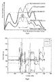
- FIG. 4 illustrates the variation of the color information provided by the three color channels R, G, B over all pixels of the same line as shown on FIG. 3 , where the same saturated segments s 1 , s 2 , s 3 , . . . are identified by the saturation of the color information provided by at least one of the three color channels R, G and B;
- FIG. 5 illustrates, in a segment of FIGS. 3 and 4 , how the difference between the color value provided by the reference color channel for a pixel of this segment and a baseline color value ⁇ si computed for this segment is added to the color value of this pixel that is provided by the saturated color channel of this segment, according to the fourth step of the embodiment of FIG. 1 ;
- FIG. 6 illustrates the variation of the color information provided by the three color channels R, G, B over all pixels of the same line as shown on FIG. 3 , resulting from the desaturation of all color channels as illustrated on FIG. 5 , at the end of the fourth step of the embodiment of FIG. 1 ;
- FIG. 7 is a flow chart illustrating a second embodiment of the method according to the invention.
- the different steps of two non-limiting embodiment of the method according to the invention will now be described in reference to FIG. 1 .
- These different steps may be provided through the use of dedicated hardware as well as hardware capable of executing software in association with appropriate software, forming together an image conversion device.
- the hardware may notably include, without limitation, digital signal processor (“DSP”) hardware, read-only memory (“ROM”) for storing software, random access memory (“RAM”), and non-volatile storage.
- DSP digital signal processor
- ROM read-only memory
- RAM random access memory
- the image conversion device can be part of an electronic consumer device as, for instance, a TV set, a cell phone, a tablet, a set-top-box, a gateway, or a camera.
- An input 8-bit RGB saturated image is provided to the image conversion device.
- this image conversion device is part of a cell phone, a tablet or a camera, this image may be directly provided through the capture of an image.
- the linear RGB color space associated with the R,G,B color channels is preferably related to an image capture device, notably the image capture device used for this capture.
- this image conversion device is part of an electronic device such as a TV set, a set-top-box, a cell phone, a tablet, or a gateway, the image may be provided by the image receiver integrated in them.
- the linear RGB color space associated with the R,G,B color channels is preferably related to the image display device associated with this electronic device or with its image receiver.
- the gamma correction is first removed in a manner known per se from the saturated image (we assume for instance a 2.2 gamma) such as to obtain an image with color data expressed in the linear RGB color space of a display device.
- This display device could be any kind of actual or virtual device, as a LCD, an OLED display, a projector, or any device complying with a standard as, for instance, ITU 709.
- To each color of a pixel of the image correspond three color values that represent the color coordinates of this color in the linear RGB space. Each color value is related to a color channel, R, G or B.
- a saturation mask S is constructed for each color channel of the image in a manner known per se in order to mark over-exposed areas of the image, more precisely to mark each pixel of this image having at least one color value which is saturated in at least one of the three color channels.
- These masks are illustrated on FIG. 2 .
- the saturation mask S is for instance calculated through the following equation 1 using a saturation color value t which may be common to all color channels, or specific to each color channel:
- I m (n, c) is the value of a color in the color channel c for a pixel belonging to a line m of the image and to a column n of the image, where m belongs to the interval [1; M] and indicates a line, where n belongs to the interval [1; N] and indicates a column, and where c belongs to the group of color channels R, G, and B and indicates the color channel.
- the threshold t is for instance common to all color channel and set to 235 (instead of 2 8 ) to account for noise.
- the value 0 for a pixel at position m,n means that the value of the color channel c associated with this pixel is saturated and that a color information related to this color channel needs to be reconstructed for this pixel;
- the value 1 for this pixel means that the value of the color channel c associated with this pixel is not saturated and that no color information needs to be reconstructed.
- the lines of adjacent pixels of the image are segmented into segments of adjacent pixels for which the corresponding values of the mask are 0. All pixels of any of those segments are clipped, i.e. have colors with at least one color channel being saturated.
- both the segmentation into segments of adjacent saturated pixels and the computation as described of a reconstructed non-saturated color information for each saturated pixel would be performed on the whole image.
- processing a saturated image as a whole would be computationally impractical.
- Such an iterative process advantageously requires only access to the color values of the line to process, plus, as explained below, the preceding and following ⁇ lines, i.e. all lines in the interval [m ⁇ ,m+ ⁇ ].
- ⁇ When having low computational resources, ⁇ may be set to 0 or 1, while larger values are preferred to increase the robustness of the method.
- lines of pixels of the image are generally horizontal and, then, columns are vertical. But lines of pixels may also be vertical and, then columns are horizontal.
- clipped pixels are grouped into segments based on their hue values and the pixels of each group (i.e. segment) are assigned a same pixel label as described below.
- the label s m,i of a pixel belonging to a line m and to a column n can be defined according to equation 2 as follows: S m,i if ⁇ H ( m,n ) ⁇ t c and S m ( n,c ) ⁇ 1 S m,(i+1) if ⁇ H ( m,n ) ⁇ t c and S m ( n,c ) ⁇ 1 ⁇ otherwise
- i belongs to the interval [1,L m ], L m being the number of clipped segments in line m
- H m (n) is the hue of this pixel, as defined above.
- this segmentation step of a line m comprising color saturated pixels there are L m segments s 1 , s 2 , s 3 , . . . , s Lm of color saturated pixels in this line, the color values of them need to be reconstructed for a same at least one color channel.
- the color channel of the RGB color space that is saturated can be identity in each segment s 1 , s 2 , s 3 , . . . .
- the grouping process of clipped pixels with similar hue values in each line of the image is optional but preferred, because it ensures that pixels of similar hues will be treated similarly, and therefore will likely obtain a more coherent appearance after reconstruction of color information for desaturation.
- a third step of the first embodiment for each s i of the saturated segments s 1 , s 2 , . . . , s i , . . . , s Lm of the line m, at least one color channel that is not saturated is selected among the different color channels providing color information for the pixels of this segment.
- This selected color channel is named reference color channel c ref because it will be used as described below for the reconstruction of color information for the pixels of this segment.
- This reference channel c ref is selected among the unclipped color channels of a segment, according to a rule defined in table 1 below, based on the identification of the saturated color channel of this segment, using for instance the color information provided by the different channels as shown on FIG. 4 .
- a fourth step of the first embodiment in each saturated segment of a line as defined above, the color value of each pixel that is related to the saturated color channel identified for this segment is replaced by a reconstructed non-saturated color value that is computed by using at least the color value of the same pixel that is related to the reference color channel of this segment as selected in the third step above.
- the saturated channels of pixels of each detected segment are desaturated according to the information given by the reference color channel c ref selected for this segment.
- a baseline color value ⁇ si related to the reference color channel c ref of the segment s i to be desaturated is computed. Such a computation is detailed below. Then, the transfer is performed as illustrated in FIG. 5 , i.e. for each pixel of this segment s i , the difference between the color value of the reference color channel c ref for this pixel and the baseline color value ⁇ si computed for this segment is added to the color value of the saturated color channel for the same pixel.
- a representative average hue H si of this segment s i is first calculated in the CIELab color space for all pixels of this segment s i . Then, the difference ⁇ H(k,n) between this average hue H si of this segment s i and the average of hues H k (n) of pixels at positions k,n, where k ⁇ m ⁇ , M+ ⁇ , i.e. in the line m as well as in the ⁇ preceding and following lines is computed in a similar way as in equation 3 above.
- the baseline color value ⁇ si is computed as the minimum color value provided by the reference color channel c ref over all pixels in the segment s i whose hue is close enough to H si according to a criteria based on a proximity parameter t hue defined by
- the baseline color value ⁇ si is computed as the minimum color value provided by the reference color channel c ref over all pixels in the segment s i of the line m, and over pixels adjacent to this segment in the in the neighbouring lines k, where k ⁇ m ⁇ , m+ ⁇ , whose hues are close enough to H si according to a criteria based on a proximity parameter t hue defined by ⁇ k
- a desaturated image I′ is obtained, which is then gamma corrected in a reverse manner compared to the above beginning of the process.
- the image is processed both horizontally and vertically. It means that, after a first processing as described above, the lines of the saturated image becomes the columns, and the columns of this saturated image becomes the lines, and the desaturation process is then repeated a second time on this saturated image, providing a second desaturated image.
- the final image is computed by taking, over the two desaturated images, the maximum color value in each color channel for each pixel.
- the corrected image is preferably alpha-blended with the uncorrected input using a simple ramp for input pixel values in the interval [t; 255].
- the method according to this first embodiment employs simple statistics computed from a small set of lines of pixels of the image to enforce hue consistency between recovered regions. By considering hue information throughout the correction, the method produces natural results. Both the segmentation and the correction step of the method operate on a small number of lines of pixels, making this method well-suited for real-time, hardware applications, such as correcting images on the display side before expanding the dynamic range. Despite the computational simplicity, this method out-performs existing partial saturation correction solutions according to several image quality and color difference metrics.
- the image conversion device used to implement this first embodiment comprises notably:
- a first module 1 configured to segment each line of pixels of an image having at least one pixel with saturated color into at least one segment of adjacent pixels the colors of which have at least one color channel in a linear RGB color space which is saturated, and,
- a second module 2 configured to desaturate pixels of each saturated segment of a line provided by the first module 1 , by selecting at least one color channel c ref that is not saturated over said segment among the different color channels providing color information in said linear RGB color space for the pixels of said segment, and by replacing the color information of each of those pixels that is provided by the at least one saturated color channel of said segment by a reconstructed non-saturated color information computed by using at least the color information provided by the selected at least one non-saturated color channel c ref of said pixel.
- a saturation mask S is constructed as in the first embodiment above for each color channel of the image in a manner known per se in order to mark over-exposed areas of the image, more precisely to mark each pixel of this image having at least one color value which is saturated in at least one of the three color channels.
- the image is segmented into regions of color-saturated pixels.
- the image is initially segmented into labelled regions of adjacent pixels by detecting connecting color components within the saturation mask.
- pixels that are assigned to a zero value in the saturation mask of step 1 are given a same segmentation label (i.e. be part of the same region) if they are neighbors.
- Two pixels are considered as neighbor when the spatial pixel distance between these pixels is less or equal to a spatial distance neighbor threshold. This is considered as neighbor criteria.
- the spatial distance neighbor threshold is generally comprised between 4 and 8 pixels. Pixels that are assigned to a zero value in the saturation mask of step 1 are given different segmentation labels if they do not fit the neighbor criteria, will therefore be considered as belonging to different initial regions.
- a third step of this second embodiment for each of the saturated regions r 1 , r 2 , . . . , r i , . . . , r L′ , at least one color channel that is not saturated is selected among the different color channels providing color information for the pixels of this saturated region.
- This selected color channel is named reference color channel c′ ref,ri and will be used as described below in step 4 for the reconstruction of color information for the pixels of this region r i .
- a specific reference channel c′ ref,ri is selected for each region r i as described in the third step of the first embodiment.
- the fourth step of this second embodiment is similar to the fourth step of the first embodiment, if the term “segment” is replaced by “region”.
- the saturated color channel(s) of pixels are desaturated. More precisely, the color value of each pixel of this region that is related to the saturated color channel identified for this region is replaced, as in step 4 of the first embodiment, by a reconstructed non-saturated color value.
- a baseline color value ⁇ ′ ri related to the reference color channel c′ ref,ri of the region r i to be desaturated is computed for each saturated region r i .
- This baseline color value ⁇ ′ ri is for instance taken as the minimum color value provided by the reference channel c′ ref,ri over all pixels in this saturated region r i , and is computed according to the following equation:
- ⁇ ri ′ min k ⁇ r i ⁇ ⁇ ( I ⁇ ( k , C ref , ri ) ) , where k indicates a pixel location within the region r i .
- the reconstructed non-saturated color value of this pixel is obtained by adding the color value of the saturated color channel for this pixel and the difference between the color value of the reference color channel c ref,ri for this pixel and the baseline color value ⁇ ′ ri computed for this region.
- the computation of the baseline ⁇ ′ ri is done per saturated region. This improves consistency in the image as more pixels are involved for computing this baseline and as it allows advantageously the different saturated regions to follow the image structure more accurately.
- a desaturated image I′ is obtained, which is then gamma corrected in a reverse manner compared to the beginning of the process.
- the image conversion device used to implement this second embodiment comprises notably:
- a first module 1 ′ configured to segment an image in regions of pixels the colors of which have at least one color channel in a linear RGB color space which is color saturated
- a second module 2 ′ configured to desaturate pixels of each saturated region (r i ) provided by the first module 1 ′ by selecting at least one color channel (c ref , c′ ref,ri ) that is not saturated over said pixels of said region (s i ; r i ) and, for each of those pixels, by replacing the color information of said pixel that is provided by the at least one saturated color channel of said region by the sum of the color information provided by said at least one saturated color channel of said region for said pixel and of the difference between the color information provided by the selected at least one non-saturated color channel (c ref ; c′ ref,ri ) for said pixel and a baseline color value ( ⁇ si ; ⁇ ′ si ) computed for the region (s i ; r i ) of said pixel
- the image conversion device used to implement the first or the second embodiment, as any other embodiment as claimed below may comprise various forms of hardware, software, firmware, special purpose processors, or combinations thereof.
- the invention may be notably implemented as a combination of hardware and software.
- the software may be implemented as an application program tangibly embodied on a program storage unit.
- the application program may be uploaded to, and executed by, a machine comprising any suitable architecture.
- the machine is implemented on a computer platform having hardware such as one or more central processing units (“CPU”), a random access memory (“RAM”), and input/output (“I/O”) interfaces.
- the computer platform may also include an operating system and microinstruction code.
- various processes and functions described herein may be either part of the microinstruction code or part of the application program, or any combination thereof, which may be executed by a CPU.
- various other peripheral units may be connected to the computer platform such as an additional data storage unit and a monitor display device to display the images before and after desaturation.
- This image conversion device can be notably part of an electronic device such as a TV set, a cell phone, a tablet, a set-top-box, a gateway, or a camera.
- the method of conversion of a saturated image into a de-saturated image takes advantage of the spatial RGB channel correlation present in natural images. Instead of relying on complex image analysis, the method according to the invention employs simple statistics computed from a small set of pixels of the image.
Abstract
Description
thus providing said converted non-saturated image.
where Im(n, c) is the value of a color in the color channel c for a pixel belonging to a line m of the image and to a column n of the image, where m belongs to the interval [1; M] and indicates a line, where n belongs to the interval [1; N] and indicates a column, and where c belongs to the group of color channels R, G, and B and indicates the color channel. For a 8-bit RGB image, the threshold t is for instance common to all color channel and set to 235 (instead of 28) to account for noise.
S m,i if ΔH(m,n)<t c and S m(n,c)≡1
S m,(i+1) if ΔH(m,n)≧t c and S m(n,c)≡1
∅ otherwise
where i belongs to the interval [1,Lm], Lm being the number of clipped segments in line m,
where the function ΔH(m,n) for a pixel position m,n is defined in equation 3:
ΔH(m,n)=min(|H m(n)−H m(n+1)|,360−|H m(n)−H m(n+1)|) eq. (3)
where Hm(n) is the hue of this pixel, as defined above.
| TABLE 1 | |||
| Nb | Saturated color channel(s) | Reference color channel(s) | |
| 1 | | Green | |
| 2 | Green | Blue and/or |
|
| 3 | Blue | Green | |
| 4 | Red and Green | Blue | |
| 5 | Red and Blue | Green | |
| 6 | Blue and Green | Red | |
| 7 | Red, Blue and Green | Luminance expansion (see below) | |
ρs
where kε{m−α, m+α}, where preferably, thue equal approximately 20°.
-
- 1. Colors of pixels of the image are converted in a manner known per se from the RGB color space to the CIE Lab color space.
- 2. For each labelled region rεR we compute an average color value using
-
- where |r| indicates the number of pixels within this region r.
- 3. For each labelled region r, we compute a color difference between r and every other labelled region ρ using ΔEr(ρ)=√{square root over ((Labr−Labρ)2)}
- 4. For each labelled region r, we additionally compute its spatial distance Dr(ρ) to each other labelled region ρ using the following:
- a. ΔMr(ρ)=min|Mr−Mρ| where M indicates the vertical coordinates of each region in the image,
- b. ΔNr(ρ)=min|Nr−Nρ| where N indicates the horizontal coordinates of each region in the image,
- c. Dr(ρ)=√{square root over ((ΔMr(ρ)2+(ΔNr (ρ)2))}
- 5. Finally we merge labelled regions which have a color difference ΔEr(ρ) to each other labelled region ρ less than a color distance merging threshold, and a spatial distance Dr(ρ) to each other labelled region ρ of less than spatial distance merging threshold.
The color distance merging threshold is for instance equal to 10, and the spatial distance merging threshold is for instance equal to 1% of the largest dimension of the image.
where k indicates a pixel location within the region ri.
Claims (7)
Applications Claiming Priority (4)
| Application Number | Priority Date | Filing Date | Title |
|---|---|---|---|
| EP14305142.3 | 2014-01-31 | ||
| EP14305142 | 2014-01-31 | ||
| EP14305142 | 2014-01-31 | ||
| PCT/EP2015/051168 WO2015113881A1 (en) | 2014-01-31 | 2015-01-21 | Method for conversion of a saturated image into a non-saturated image |
Publications (2)
| Publication Number | Publication Date |
|---|---|
| US20160352975A1 US20160352975A1 (en) | 2016-12-01 |
| US9912839B2 true US9912839B2 (en) | 2018-03-06 |
Family
ID=50231089
Family Applications (1)
| Application Number | Title | Priority Date | Filing Date |
|---|---|---|---|
| US15/115,669 Active US9912839B2 (en) | 2014-01-31 | 2015-01-21 | Method for conversion of a saturated image into a non-saturated image |
Country Status (6)
| Country | Link |
|---|---|
| US (1) | US9912839B2 (en) |
| EP (1) | EP3100449B1 (en) |
| JP (1) | JP6499188B2 (en) |
| KR (1) | KR20160117450A (en) |
| CN (1) | CN105940666B (en) |
| WO (2) | WO2015113655A1 (en) |
Cited By (2)
| Publication number | Priority date | Publication date | Assignee | Title |
|---|---|---|---|---|
| US20210319537A1 (en) * | 2020-04-10 | 2021-10-14 | Canon Kabushiki Kaisha | Image processing method, image processing apparatus, image processing system, and memory medium |
| US11202032B2 (en) * | 2019-12-20 | 2021-12-14 | Fondation B-Com | Method for converting an image and corresponding device |
Families Citing this family (13)
| Publication number | Priority date | Publication date | Assignee | Title |
|---|---|---|---|---|
| US9911181B2 (en) * | 2013-12-27 | 2018-03-06 | Thomson Licensing | Method for inverse tone mapping of an image |
| JP6210081B2 (en) * | 2015-03-23 | 2017-10-11 | カシオ計算機株式会社 | Decoding device, decoding method, and program |
| US10068346B2 (en) * | 2016-01-13 | 2018-09-04 | Thomson Licensing | Color distance determination |
| EP3226203A1 (en) | 2016-03-30 | 2017-10-04 | Thomson Licensing | Method for detection of saturated pixels in an image |
| US10319113B2 (en) * | 2017-06-21 | 2019-06-11 | Foveon, Inc. | Method for recovering highlights and saturated regions and extending dynamic range in a digital image |
| KR102117050B1 (en) * | 2017-09-08 | 2020-05-29 | 삼성전자주식회사 | Electronic device and method for human segmentation in image |
| US10645357B2 (en) * | 2018-03-01 | 2020-05-05 | Motorola Mobility Llc | Selectively applying color to an image |
| US11074677B2 (en) | 2018-03-29 | 2021-07-27 | Dolby Laboratories Licensing Corporation | Dynamic range extension of partially clipped pixels in captured images |
| US10874006B1 (en) | 2019-03-08 | 2020-12-22 | Abl Ip Holding Llc | Lighting fixture controller for controlling color temperature and intensity |
| US11259377B2 (en) * | 2019-05-17 | 2022-02-22 | Abl Ip Holding Llc | Color temperature and intensity configurable lighting fixture using de-saturated color LEDs |
| CA3096225C (en) | 2019-10-17 | 2022-11-15 | Abl Ip Holding Llc | Selectable lighting intensity and color temperature using luminaire lens |
| US11641708B2 (en) | 2020-08-28 | 2023-05-02 | Abl Ip Holding Llc | Light fixture controllable via dual networks |
| US20220294968A1 (en) * | 2021-03-10 | 2022-09-15 | Intrinsic Innovation Llc | Systems and methods for high dynamic range image reconstruction |
Citations (6)
| Publication number | Priority date | Publication date | Assignee | Title |
|---|---|---|---|---|
| US3971065A (en) | 1975-03-05 | 1976-07-20 | Eastman Kodak Company | Color imaging array |
| US20080055616A1 (en) | 2006-09-06 | 2008-03-06 | Scott Kevin C | Color correction method |
| EP2367360A2 (en) | 2010-03-18 | 2011-09-21 | Balser AG | Method for correcting color errors in images from digital color cameras |
| US20120314971A1 (en) | 2011-06-07 | 2012-12-13 | Microsoft Corporation | Automatic exposure correction of images |
| US20130321679A1 (en) * | 2012-05-31 | 2013-12-05 | Apple Inc. | Systems and methods for highlight recovery in an image signal processor |
| US8861851B2 (en) * | 2011-05-13 | 2014-10-14 | Dolby Laboratories Licensing Corporation | Color highlight reconstruction |
Family Cites Families (3)
| Publication number | Priority date | Publication date | Assignee | Title |
|---|---|---|---|---|
| JP2005284423A (en) * | 2004-03-29 | 2005-10-13 | Seiko Epson Corp | Image processor and image processing method |
| US8270753B2 (en) * | 2005-06-14 | 2012-09-18 | Nikon Corporation | Image processing device, computer program product, and image processing method to restore signals in a saturated area |
| CN103002225B (en) * | 2011-04-20 | 2017-04-12 | 高通科技公司 | Multiple exposure high dynamic range image capture |
-
2014
- 2014-08-28 WO PCT/EP2014/068295 patent/WO2015113655A1/en active Application Filing
-
2015
- 2015-01-21 WO PCT/EP2015/051168 patent/WO2015113881A1/en active Application Filing
- 2015-01-21 EP EP15701180.0A patent/EP3100449B1/en active Active
- 2015-01-21 KR KR1020167020683A patent/KR20160117450A/en not_active Application Discontinuation
- 2015-01-21 CN CN201580006613.9A patent/CN105940666B/en active Active
- 2015-01-21 US US15/115,669 patent/US9912839B2/en active Active
- 2015-01-21 JP JP2016549145A patent/JP6499188B2/en not_active Expired - Fee Related
Patent Citations (6)
| Publication number | Priority date | Publication date | Assignee | Title |
|---|---|---|---|---|
| US3971065A (en) | 1975-03-05 | 1976-07-20 | Eastman Kodak Company | Color imaging array |
| US20080055616A1 (en) | 2006-09-06 | 2008-03-06 | Scott Kevin C | Color correction method |
| EP2367360A2 (en) | 2010-03-18 | 2011-09-21 | Balser AG | Method for correcting color errors in images from digital color cameras |
| US8861851B2 (en) * | 2011-05-13 | 2014-10-14 | Dolby Laboratories Licensing Corporation | Color highlight reconstruction |
| US20120314971A1 (en) | 2011-06-07 | 2012-12-13 | Microsoft Corporation | Automatic exposure correction of images |
| US20130321679A1 (en) * | 2012-05-31 | 2013-12-05 | Apple Inc. | Systems and methods for highlight recovery in an image signal processor |
Non-Patent Citations (18)
| Title |
|---|
| Abel et al., "Restoring a Clipped Signal", International Conference on Acoustics, Speech, and Signal Processing, Toronto, Canada, Apr. 14, 1991, pp. 1745-1748. |
| Banterle et al., "Inverse Tone Mapping", 4th International Conference on Computer Graphics and Interactive Techniques in Australasia and Southeast Asia, Kuala Lumpur, Malaysia, Nov. 29, 2006, pp. 349-356. |
| Didyk et al., "Enhancement of Bright Video Features for HDR Displays", Eurographics Symposium on Rendering, Graphics Forum, Sarajevo, Bosnia and Herzegovina, Jun. 23, 2008, pp. 1265-1274. |
| Elboher et al., "Recovering Color and Details of Clipped Image Regions", 2010 International Conference on Computer Graphics, Visualization, Computer Vision and Image Processing, Freiburg, Germany, Jul. 27, 2010, pp. 1-9. |
| Fu et al., "Correcting Saturated Pixels in Images", Proceedings of SPIE 8299, Digital Photography VIII, Jan. 2012, pp. 1-11. |
| Guo et al., "Correcting Over-Exposure in Photographs", 2010 IEEE Conference on Computer Vision and Pattern Recognition, San Franscisco, California, USA, Jun. 13, 2010, pp. 515-521. |
| Hasinoff, W., "Saturation (imaging)", Encyclopedia of Computer Vision, Springer, New York, 2014, pp. 699-701, (published before this application Jul. 2016). |
| Kovaleski et al., "High-quality brightness enhancement functions for real-time reverse tone mapping", Visual Computer, vol. 25, No. 5, May 2009, pp. 539-547. |
| Masia et al., "Evaluation of Reverse Tone Mapping Through Varying Exposure Conditions", ACM SIGGRAPH Asia 2009, Yokohama, Japan, Dec. 16, 2009, pp. 1-8. |
| Masood et al., "Automatic Correction of Saturated Regions in Photographs using Cross-Channel Correlation", Pacific Graphics, vol. 28, No. 7, Oct. 2009, pp. 1861-1869. |
| Reinhard et al., "Colour Spaces for Colour Transfer", IAPR Third International Workshop on Computational Color Imaging, Milan, Italy, Apr. 20, 2011, pp. 1-15. |
| Rempel et al., "Ldr2Hdr: On-the-fly Reverse Tone Mapping of Legacy Video and Photographs", SIGGRAPH 2007 Special Interest Group on Computer Graphics and Interactive Techniques Conference, San Diego, California, USA, Aug. 5, 2007, pp. 1-6. |
| Rouf et al., "Gradient Domain Color Restoration of Clipped Highlights", 2012 IEEE Computer Society Conference on Computer Vision and Pattern Recognition Workshops (CVPRW), Providence, Rhode Island, USA, Jun. 16, 2012, pp. 7-14. |
| Shen et al., "Over-exposure image correction with automatic texture synthesis", 4th International Congress on Imagine and Signal Processing (CISP), Shanghai, China, Oct. 15, 2011, pp. 1-8. |
| Wang et al., "High Dynamic Range Image Hallucination", 18th Eurographics Symposium on Rendering, Grenoble, France, Jun. 25, 2007, pp. 321-326. |
| Wetzstein et al., "Sensor saturation in Fourier multiplexed imaging", 2010 IEEE Conference on Computer Vision and Pattern Recognition (CVPR), San Francisco, California, USA, Jun. 13, 2010, pp. 1-12. |
| Xu et al., "Correction of Clipped Pixels in Color Images", IEEE Transactions on Visualization and Computer Graphics, vol. 17, No. 3, Mar. 2011, pp. 333-344. |
| Zhang et al., "Estimation of saturated pixel values in digital color imaging", Journal of the Optical Society of America, vol. 21, No. 12, Dec. 2004, pp. 2301-2310. |
Cited By (2)
| Publication number | Priority date | Publication date | Assignee | Title |
|---|---|---|---|---|
| US11202032B2 (en) * | 2019-12-20 | 2021-12-14 | Fondation B-Com | Method for converting an image and corresponding device |
| US20210319537A1 (en) * | 2020-04-10 | 2021-10-14 | Canon Kabushiki Kaisha | Image processing method, image processing apparatus, image processing system, and memory medium |
Also Published As
| Publication number | Publication date |
|---|---|
| KR20160117450A (en) | 2016-10-10 |
| EP3100449B1 (en) | 2020-07-15 |
| EP3100449A1 (en) | 2016-12-07 |
| JP2017505956A (en) | 2017-02-23 |
| CN105940666B (en) | 2019-05-31 |
| WO2015113655A1 (en) | 2015-08-06 |
| JP6499188B2 (en) | 2019-04-10 |
| WO2015113881A1 (en) | 2015-08-06 |
| CN105940666A (en) | 2016-09-14 |
| US20160352975A1 (en) | 2016-12-01 |
Similar Documents
| Publication | Publication Date | Title |
|---|---|---|
| US9912839B2 (en) | Method for conversion of a saturated image into a non-saturated image | |
| JP5300595B2 (en) | Image processing apparatus and method, and computer program | |
| EP3155593B1 (en) | Method and device for color processing of digital images | |
| US7652717B2 (en) | White balance correction in digital camera images | |
| US7876970B2 (en) | Method and apparatus for white balancing digital images | |
| KR20170107487A (en) | Metadata-based image processing method and apparatus | |
| US20170019569A1 (en) | Information processing apparatus, method for processing information, and computer program | |
| CN112351195B (en) | Image processing method, device and electronic system | |
| JP2010200295A (en) | Method and device for maintaining image background by using multiple gaussian distribution models | |
| EP3437066B1 (en) | Method for detection of saturated pixels in an image | |
| US9172843B2 (en) | Image processing device and computer-readable medium | |
| JP2010034713A (en) | Photographic image processing method, photographic image processing program and photographic image processing apparatus | |
| US9998631B2 (en) | Information processing apparatus, method for processing information, and computer program | |
| Assefa et al. | Correction of over-exposure using color channel correlations | |
| EP3407252B1 (en) | Image processing apparatus, image processing method, and storage medium | |
| WO2016113407A1 (en) | Methods and apparatus for groupwise contrast enhancement | |
| WO2016102386A1 (en) | Methods and systems for color processing of digital images | |
| Gil Rodríguez et al. | Issues with common assumptions about the camera pipeline and their impact in hdr imaging from multiple exposures | |
| US9582744B2 (en) | Image processing device and computer-readable medium using photographic and non-photographic correspondence data | |
| CN110827287B (en) | Method, device and equipment for determining background color confidence and image processing | |
| JP2008147714A (en) | Image processor and image processing method | |
| JP5632937B2 (en) | Image processing apparatus and method, and computer program | |
| JP5775413B2 (en) | Image processing apparatus, image processing method, and program | |
| JP2015149545A (en) | Image processing apparatus, control method of the same, and program | |
| CN111885281A (en) | Image processing |
Legal Events
| Date | Code | Title | Description |
|---|---|---|---|
| AS | Assignment |
Owner name: THOMSON LICENSING, FRANCE Free format text: ASSIGNMENT OF ASSIGNORS INTEREST;ASSIGNORS:KERVEC, JONATHAN;ABEBBE, MEKIDES ASSEFA;POULI, TANIA FOTEINI;AND OTHERS;SIGNING DATES FROM 20160706 TO 20160720;REEL/FRAME:041519/0471 |
|
| STCF | Information on status: patent grant |
Free format text: PATENTED CASE |
|
| AS | Assignment |
Owner name: INTERDIGITAL VC HOLDINGS, INC., DELAWARE Free format text: ASSIGNMENT OF ASSIGNORS INTEREST;ASSIGNOR:THOMSON LICENSING;REEL/FRAME:047289/0698 Effective date: 20180730 |
|
| AS | Assignment |
Owner name: INTERDIGITAL MADISON PATENT HOLDINGS, SAS, FRANCE Free format text: ASSIGNMENT OF ASSIGNORS INTEREST;ASSIGNOR:INTERDIGITAL VC HOLDINGS, INC.;REEL/FRAME:053048/0181 Effective date: 20190911 |
|
| MAFP | Maintenance fee payment |
Free format text: PAYMENT OF MAINTENANCE FEE, 4TH YEAR, LARGE ENTITY (ORIGINAL EVENT CODE: M1551); ENTITY STATUS OF PATENT OWNER: LARGE ENTITY Year of fee payment: 4 |