JP5300595B2 - Image processing apparatus and method, and computer program - Google Patents
Image processing apparatus and method, and computer program Download PDFInfo
- Publication number
- JP5300595B2 JP5300595B2 JP2009128568A JP2009128568A JP5300595B2 JP 5300595 B2 JP5300595 B2 JP 5300595B2 JP 2009128568 A JP2009128568 A JP 2009128568A JP 2009128568 A JP2009128568 A JP 2009128568A JP 5300595 B2 JP5300595 B2 JP 5300595B2
- Authority
- JP
- Japan
- Prior art keywords
- image
- image processing
- lookup table
- correction
- look
- Prior art date
- Legal status (The legal status is an assumption and is not a legal conclusion. Google has not performed a legal analysis and makes no representation as to the accuracy of the status listed.)
- Active
Links
Images


Classifications
-
- H—ELECTRICITY
- H04—ELECTRIC COMMUNICATION TECHNIQUE
- H04N—PICTORIAL COMMUNICATION, e.g. TELEVISION
- H04N1/00—Scanning, transmission or reproduction of documents or the like, e.g. facsimile transmission; Details thereof
- H04N1/46—Colour picture communication systems
- H04N1/56—Processing of colour picture signals
- H04N1/60—Colour correction or control
- H04N1/62—Retouching, i.e. modification of isolated colours only or in isolated picture areas only
Landscapes
- Engineering & Computer Science (AREA)
- Multimedia (AREA)
- Signal Processing (AREA)
- Image Processing (AREA)
- Facsimile Image Signal Circuits (AREA)
- Color Image Communication Systems (AREA)
Description
本発明は、入力された画像の明るさを補正する画像処理装置および方法に関する。 The present invention relates to an image processing apparatus and method for correcting the brightness of an input image.
従来より、デジタルカメラで撮影された写真画像データに対して様々な補正を行い、好適な写真画像を表示・プリントする方法が、様々提案されている。このような画像補正方法は、大別すると、画像全体に均一的な補正を行う均一補正と、画像の局所的な性質に応じて補正量が変化する局所的補正の二つに分けて考えることができる。 Conventionally, various methods for performing various corrections on photographic image data taken with a digital camera and displaying / printing a suitable photographic image have been proposed. Such image correction methods can be broadly divided into two types: uniform correction, which performs uniform correction on the entire image, and local correction, in which the correction amount changes according to the local nature of the image. Can do.
前者の均一補正の例を挙げると、特許文献1に示されているようなカラーバランス補正がある。特許文献1では、画像の輝度ヒストグラムを算出し、累積度数に応じて画像中のハイライト・シャドーポイントを算出する。ハイライト・シャドーポイントの色差成分が0であれば、該画像データのカラーバランスは適正と判断する。一方で、色差成分が0ではない場合、カラーバランスが崩れていると判断し、輝度・色差空間において、ハイライト・シャドーポイントの色差を0とするような回転行列を画像に対して一律に処理する。
As an example of the former uniform correction, there is a color balance correction as disclosed in
一方、後者の局所的補正については、覆い焼きに代表されるような、画像の空間的な位置に応じて補正量が変化する種類の画像処理が挙げられる。覆い焼き処理とは、例えば、人物などの被写体が暗く、背景が明るい場合に、暗い人物領域の輝度は大きく上昇させ、明るい背景領域の輝度はさほど変化させないことにより、背景の白トビを抑えて人物領域の明るさを適正に補正するというものである。このような覆い焼き処理としては、従来より、特許文献2や特許文献3が提案されている。両者とも、入力画像に対してフィルタ処理を施して低周波画像、すなわちボケ画像を生成し、該ボケ画像を空間的な明るさの制御因子として用いることで、デジタル処理における覆い焼き処理を実現している。 On the other hand, the latter local correction includes a type of image processing in which the correction amount changes according to the spatial position of the image, as represented by dodging. Dodge processing, for example, when the subject such as a person is dark and the background is bright, the brightness of the dark person area is greatly increased, and the brightness of the bright background area is not changed so much, thereby suppressing white background. This is to correct the brightness of the person area appropriately. Conventionally, Patent Document 2 and Patent Document 3 have been proposed as such dodging processes. In both cases, the input image is filtered to generate a low-frequency image, that is, a blurred image, and the blurred image is used as a spatial brightness control factor to realize dodging processing in digital processing. ing.
近年では、プリンタの機能が豊富になり、プリント以外にもコピー機能やメモリカードから写真データを直接プリントする機能も標準搭載されている。また近年プリント速度も目覚しい進歩を遂げており、今後も継続的に進化を要求されている。一方で、プリンタが搭載しているハードウェアリソースは、近年のパーソナルコンピュータほど潤沢なものではなく、CPU速度やRAM容量、さらにはRAMのアクセス速度などは限定的な能力であることが一般的である。さらにプリンタ本体のコストダウン要求も厳しく、可能な限り低リソースで動作する画像処理が望まれている。すなわち、プリンタ本体のハードウェア性能はその能力を維持またはダウンさせつつ、プリント速度等の性能向上が望まれるという相矛盾した状況となっている。 In recent years, printer functions have become abundant, and in addition to printing, a copy function and a function for printing photo data directly from a memory card are also standard. In recent years, the printing speed has made remarkable progress, and there is a demand for continuous improvement in the future. On the other hand, hardware resources installed in printers are not as rich as personal computers in recent years, and CPU speed, RAM capacity, and RAM access speed are generally limited capabilities. is there. Further, the cost reduction of the printer main body is severe, and image processing that operates with as low resources as possible is desired. In other words, the hardware performance of the printer main body is in a contradictory situation where it is desired to improve the performance such as the printing speed while maintaining or reducing the capability.
このような現状において、高速に画像処理を実行するための有効な手段として提案されているのが、3次元ルックアップテーブル(以下、3DLUT)を用いた画像処理である。以下では、3DLUT方式を用いた画像処理の有効性について説明する。 Under such circumstances, image processing using a three-dimensional lookup table (hereinafter referred to as 3DLUT) has been proposed as an effective means for executing image processing at high speed. Hereinafter, the effectiveness of image processing using the 3DLUT method will be described.
例えば、入力画像に対して、特許文献1のようなカラーバランス補正と、輝度階調補正と、彩度補正を同時に行う場合を考える。これらの処理を、画像全体の各画素全てに施した場合と、補正後のRGB 3DLUTを構成し、補間演算によって画像全体の画素を補正した場合とで演算量を比較する。
For example, consider a case where color balance correction, luminance gradation correction, and saturation correction are performed simultaneously on an input image as in
まず、前者の画像全体の各画素に対して処理を行う場合について考える。入力画像の各画素値がRGBで表現されている場合、例えば輝度色差空間であるYCbCr値に変換する。この処理には、9回の乗算を必要とする。該YCbCr値に対して特許文献1に記載されているような補正用の3次元回転行列を施し、カラーバランス補正後のY'Cb'Cr'値を得る。この処理には、9回の乗算を必要とする。次に、Y'値に対して所定の階調補正を行い、Y''値を得る。さらに、Cb'Cr'値に対して彩度強調係数を乗じ、Cb''Cr''値を得る。この処理には2回の乗算を必要とする。最後に、補正後のY''Cb''Cr''値を公知の公式によってR''G''B''値に変換する処理をおこなう。この処理には9回の乗算が必要である。従って、この一連の処理には、合計で29回の乗算が必要となる。この処理を各画素に繰り返すと、例えば、3000×2000画素の画像の場合、17400万回の乗算が必要となる。
First, consider the case where the former image is processed for each pixel. When each pixel value of the input image is expressed in RGB, for example, it is converted into a YCbCr value that is a luminance color difference space. This process requires 9 multiplications. A three-dimensional rotation matrix for correction as described in
一方、3DLUTを用いた場合について説明する。良く知られているように、3DLUTを用いた方式では、3DLUTを所定間隔の格子状に分割し、各格子点に対して補正後のRGB値を算出し、格納しておく。ここでは、例えば、グリッド間隔を32とし、9^3=729点の格子点が存在すると仮定する。このとき、各格子点のRGB値に対して上記処理を行うと、29×729回の乗算が必要となる。このようにして生成した3DLUTを、各画素に対して公知の補間演算により適用する。例えば四面体補間を用いる場合、1画素あたり5回の乗算で、補正後のRGB値を得ることができる。すなわち、3DLUTによる画像全体の乗算回数は、次式で表される。
乗算回数=29×729+(3000×4000)×5≒6002万回
On the other hand, a case where 3DLUT is used will be described. As is well known, in the method using 3DLUT, 3DLUT is divided into grids with predetermined intervals, and corrected RGB values are calculated and stored for each grid point. Here, for example, it is assumed that the grid interval is 32 and there are 9 ^ 3 = 729 lattice points. At this time, if the above processing is performed on the RGB values of the respective grid points, 29 × 729 multiplications are required. The 3DLUT generated in this way is applied to each pixel by a known interpolation calculation. For example, when tetrahedral interpolation is used, a corrected RGB value can be obtained by multiplying 5 times per pixel. That is, the number of multiplications of the entire image by 3DLUT is expressed by the following equation.
Multiplication count = 29 x 729 + (3000 x 4000) x 5 ≒ 620,000 times
両者の総乗算回数を比較すると、前者に比べ後者の演算回数は1/3程度であり、3DLUT方式が極めて有効であることがわかる。 Comparing the total number of multiplications of the two, it can be seen that the number of operations of the latter is about 1/3 of that of the former, and that the 3DLUT method is extremely effective.
一方で、プロのカメラマンではない一般のアマチュアカメラマンが撮影した写真画像には、例えば色かぶりした逆光写真など、複数の失敗要因を含んだ画像が数多く存在する。このような画像には、カラーバランス補正によって色かぶりを除去した後、背景はそのままで、暗くなった被写体領域のみ、輝度成分を上昇させるといった、非常に複雑な補正処理を施す必要が生じる。 On the other hand, many photographic images taken by a general amateur photographer who is not a professional photographer include a plurality of images including a plurality of failure factors such as a backlit photograph with a color cast. For such an image, after removing the color cast by color balance correction, it is necessary to perform a very complicated correction process such that the luminance component is increased only in the darkened subject area without changing the background.
このような、覆い焼き補正に代表される局所的な補正と上記カラーバランス補正のような画像均一の補正を同時に行うことを考えた場合、上記のような1つの3DLUTのみで制御することが、非常に困難であるという問題がある。 When considering the local correction represented by the dodging correction and the image uniformity correction such as the color balance correction at the same time, it is possible to control with only one 3DLUT as described above. There is a problem that it is very difficult.
上述したように3DLUTは補間演算によって適用されるため、例えば補間後の画素値から明るさ成分のみを抽出し、該成分を局所的に制御することも考えられなくはないが、処理が複雑になり、実現するために必要な演算規模や回路規模が大きくなってしまう。 As described above, since 3DLUT is applied by interpolation calculation, for example, it is possible to extract only the brightness component from the interpolated pixel value and control the component locally, but the processing is complicated. As a result, the computation scale and circuit scale required to achieve this increase.
本発明は上記課題を鑑みたもので、ハードリソース(例えばCPU、RAM)が高性能ではないシステムにおいて、画像均一の補正(例えばカラーバランス補正)と局所的な補正(例えば覆い焼き処理)を、低演算量低メモリで実現することを目的とする。 The present invention has been made in view of the above problems, and in a system where hardware resources (for example, CPU, RAM) are not high performance, image uniformity correction (for example, color balance correction) and local correction (for example, dodging processing) The purpose is to realize low calculation amount and low memory.
上記課題を解決するために、本発明は、画像の特徴量に基づいて前記画像を補正するための第1のルックアップテーブルを生成する第1の生成手段と、前記画像に含まれる特定オブジェクトの属性情報を前記第1のルックアップテーブルを用いて更新する更新手段と、前記更新手段によって更新された属性情報に基づいて前記特定オブジェクトを補正するための第2のルックアップテーブルを生成する第2の生成手段と、前記画像に対して前記生成された第1および第2のルックアップテーブルを適用する補間手段とを有し、前記補間手段は、前記画像の低周波画像を用いて前記第2のルックアップテーブルの適用強度を制御することを特徴とする画像処理装置を提供する。
他の発明は、上記画像処理装置における画像処理方法、及び該方法を実行するためのプログラムを記憶した記憶媒体に関するものである。
In order to solve the above-described problem, the present invention provides a first generation unit that generates a first lookup table for correcting the image based on a feature amount of the image, and a specific object included in the image. Updating means for updating attribute information using the first lookup table; and generating a second lookup table for correcting the specific object based on the attribute information updated by the updating means. Generating means and interpolation means for applying the generated first and second lookup tables to the image, the interpolation means using the low-frequency image of the image to An image processing apparatus is provided that controls the application strength of the lookup table.
Another invention relates to an image processing method in the image processing apparatus and a storage medium storing a program for executing the method.
本発明は、複数の補間部を直列接続し、一方の補間部で画像全体に対して均一な補正処理を行い、他方の補間部でその補間強度を制御パラメータで制御する。これにより、極めて簡単な構成で、従来の課題であった、均一補正と局所補正を同時に行う処理を実現させることができる。 In the present invention, a plurality of interpolation units are connected in series, one interpolation unit performs uniform correction processing on the entire image, and the other interpolation unit controls the interpolation strength with a control parameter. As a result, it is possible to realize a process for simultaneously performing uniform correction and local correction, which has been a conventional problem, with an extremely simple configuration.
[実施例]
(第1の実施例)
以下に、本発明における好適な第1の実施例について説明する。なお、以下の記載はプリンタ本体内部の画像処理部を想定して説明を行うが、これはあくまで実施の1つの形態を例として示したものであり、本発明は以下の実施に限定されるものではない。
[Example]
(First embodiment)
The preferred first embodiment of the present invention will be described below. The following description will be made assuming an image processing unit inside the printer body. However, this is merely an example of the embodiment, and the present invention is limited to the following embodiment. is not.
(ハードウェアの説明)
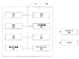
図2は、本実施例の画像処理方法が実行可能なハードウェア200の構成例を示している。201はCPU、202はRAM、203は各種制御プログラム・テーブルが格納されているROM、204は2次記憶装置(例えばハードディスク)である。205はユーザーインターフェース(例えばボタン、表示装置)である。206は外部インターフェース(例えばUSB(商標)、メモリカードリーダー)であり、該インターフェース(以下「IF206」と記す)を介して、メモリカード209から画像データを読み込んだり、パーソナルコンピュータ210に接続される。207は原稿読取装置(例えばスキャナ)、208はプリントエンジンである。
(Hardware description)
FIG. 2 shows a configuration example of
(処理のブロック図)
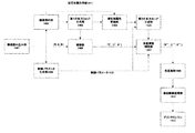
図1は、本実施例における処理のブロック図を示している。図1はハードウェア200におけるブロック図である。同図を見るとわかるように、本実施例においては、入力画像を2つの補間部107,108を直列に接続した構成により補正する。後に詳細は説明するが、後段の補間部108は、その補間強度を制御パラメータにて制御することが可能である。
(Process block diagram)
FIG. 1 shows a block diagram of processing in the present embodiment. FIG. 1 is a block diagram of the
ユーザーより、例えばプリンタにおける印刷処理などの指示がIF206を介して入力された場合、まず101において、該IFに接続されたメモリカードや、画像読取装置207から、処理対象となる画像データを読み込む。次に、画像解析部102において、画像の解析処理を行なって、画像データから特徴量を算出する。本実施例における画像解析部では、人物の顔領域を公知の顔検出技術を用いて検出し、該顔領域の属性値(平均輝度、色差成分等)を算出して顔領域が露出不足か否か判定する。さらに、画像全体のヒストグラムを算出し、その結果を解析して、画像のカラーバランスの適正度合いも判定する。上記解析結果は、第1の多次元LUT生成部104(第1の多次元ルックアップテーブル生成手段)に入力され、画像全体のカラーバランスを補正するための第1の3DLUT(第1の多次元ルックアップテーブル、ここでは3次元ルックアップテーブル)を生成する。
For example, when an instruction such as print processing in a printer is input from the user via the
次に、被写体属性更新部105において、画像解析部102で解析した被写体(特定オブジェクト)の属性情報(例えば、被写体の顔の平均輝度値)と該第1の3DLUTを用いて、被写体属性情報の更新を行う。具体的には、被写体属性情報に対して第1の3DLUTを公知の補間方法によって適用し、第1の3DLUTによる補正後の属性情報を算出する。 Next, the subject attribute update unit 105 uses the attribute information of the subject (specific object) analyzed by the image analysis unit 102 (for example, the average luminance value of the face of the subject) and the first 3DLUT, Update. Specifically, the first 3DLUT is applied to the subject attribute information by a known interpolation method, and the attribute information corrected by the first 3DLUT is calculated.
該更新された属性情報は、第2の多次元LUT生成部106(第2の多次元ルックアップテーブル生成手段)に入力される。第2の多次元LUT生成部106において、被写体を適正化することに特化した第2の3DLUT(第2の多次元ルックアップテーブル、ここでは3次元ルックアップテーブル)を生成する。該第2の3DLUTは、同部に入力された更新後の被写体属性情報を基に生成する。
The updated attribute information is input to the second multidimensional LUT generator 106 (second multidimensional lookup table generator). The second multidimensional
補正処理前の最後の準備として、制御パラメータ生成部103(制御パラメータ生成手段)において、強度調整補間部108において補間強度を制御するためのパラメータを生成する。具体的には、入力画像に対してフィルタリング処理によりボケ画像を生成し、生成したボケ画像を制御パラメータ113として、強度調整補間部108入力する。 As a final preparation before the correction process, the control parameter generation unit 103 (control parameter generation unit) generates parameters for controlling the interpolation intensity in the intensity adjustment interpolation unit. Specifically, a blur image is generated by filtering processing on the input image, and the intensity adjustment interpolation unit 108 is input as the generated blur image as the control parameter 113.
以上で、2つの3DLUTおよび制御パラメータの生成が終了する。 This completes the generation of the two 3DLUTs and the control parameters.
以降では、補正処理に関する処理の流れを説明する。画像読み込み部101で読み込んだ画像データは、各画素毎に補間部107に入力され、同部において公知の補間方法によって、前記第1の3DLUTを適用する。適用後の画素値は補間部108に入力され、同部において公知の補間方法によって、前記第2の3DLUTを適用する。このとき、前記制御パラメータに応じて、画像の局所領域毎に、第2の3DLUTの補間強度を制御する。以上の処理で補正が完了した画像データは、色変換部109においてCMYKインク色に変換され、擬似階調処理部110において、誤差拡散やディザ等の擬似階調処理が施され、その後プリントエンジン部111において、印字媒体上に画像として形成される。 Hereinafter, the flow of processing related to the correction processing will be described. The image data read by the image reading unit 101 is input to the interpolation unit 107 for each pixel, and the first 3DLUT is applied in the same unit by a known interpolation method. The pixel value after application is input to the interpolation unit 108, where the second 3DLUT is applied by a known interpolation method. At this time, the interpolation strength of the second 3DLUT is controlled for each local region of the image according to the control parameter. The image data corrected by the above processing is converted into CMYK ink colors by the color conversion unit 109, and subjected to pseudo gradation processing such as error diffusion and dithering in the pseudo gradation processing unit 110, and then the print engine unit. At 111, an image is formed on the print medium.
以上が、本実施例における処理のブロック図の説明である。 The above is the description of the block diagram of the processing in the present embodiment.
以下では、各ブロック内の詳細な処理に関して、フローチャートを参照しながら説明を行う。 Hereinafter, detailed processing in each block will be described with reference to a flowchart.
(画像読み込み部)
画像読み込み部101では、処理対象画像データの読み込みを行う。読み込みは、IF206を介して接続されているメモリカード内に含まれている画像データを読み込んだり、読み取り装置207によって原稿を光学的にスキャンして得られたデータを読み込むことで実現できる。読み込んだ画像データは、その色空間が、例えばsRGB空間であるのか、あるいはadobe RGB(米アドビ社の登録商標)空間であるのか、さらにはその他の色空間であるかを識別するためのフラグ情報と共に、次段の処理に送られる。
(Image reading part)
The image reading unit 101 reads processing target image data. Reading can be realized by reading image data included in a memory card connected via the
(画像解析部)
図3は、画像解析部102で実行されるフローチャートを示している。この処理を実行するプログラムは、実行時に二次記憶装置204からRAM202にロードされ、CPU201の制御の下に実行される。
まずS301において、入力画像のリサイズを行う。以降のヒストグラム算出や顔検出処理は、例えば入力画像が4000×3000画素の場合、全ての画素に対して処理を行うと膨大な処理量が必要となる。上記顔検出処理やヒストグラム算出処理は、画像の特徴を捉えるだけの解像度に縮小し、該縮小画像に対して処理を行うことで、全体の処理量を低減することができる。縮小解像度は特に規定しないが、例えば、VGAサイズ(640×480画素相当)に縮小すると効果的である。
(Image Analysis Department)
FIG. 3 shows a flowchart executed by the image analysis unit 102. A program for executing this processing is loaded from the
First, in S301, the input image is resized. For the subsequent histogram calculation and face detection processing, for example, when the input image is 4000 × 3000 pixels, if all pixels are processed, a huge amount of processing is required. In the face detection process and the histogram calculation process, the overall processing amount can be reduced by reducing the resolution to a level that captures the characteristics of the image and processing the reduced image. Although the reduction resolution is not particularly defined, it is effective to reduce the resolution to, for example, a VGA size (equivalent to 640 × 480 pixels).
次に、該縮小画像に対して、色変換処理を行う。これは、以降の解析処理において、共通の色空間で処理を行う方が、露出適正度判定部などにおけるパラメータ設計が容易になるからである。本実施例においては、共通色空間をsRGB空間とし、その他の色空間が入力された場合には、S302において公知の変換手段を用いてsRGB空間に変換する。 Next, color conversion processing is performed on the reduced image. This is because parameter design in the exposure appropriateness determination unit or the like is easier when processing is performed in a common color space in subsequent analysis processing. In the present embodiment, the common color space is set as the sRGB space, and when other color spaces are input, conversion into the sRGB space is performed using known conversion means in S302.
次に、S303において、画像全体のヒストグラム算出を行う。ヒストグラム算出はどのような方法を用いてもよいが、ここでは、各画素のsRGB値を輝度色差空間(例えば、YCbCr空間)に変換し、各成分毎にヒストグラムを算出するものとする。入力画像が全体的に露出不足の状態で撮影された場合、輝度成分ヒストグラム(8bit精度とする)は図4に示すように、暗部に偏った分布となる。 Next, in S303, histogram calculation of the entire image is performed. Any method may be used for calculating the histogram. Here, the sRGB value of each pixel is converted into a luminance color difference space (for example, YCbCr space), and a histogram is calculated for each component. When the input image is photographed in a state of underexposure as a whole, the luminance component histogram (with 8-bit accuracy) has a distribution biased toward the dark part as shown in FIG.
次に、S304において、画像中から所望の被写体を検出する。本実施例において被写体は特に限定するものではないが、ここでは人物の顔を例に挙げて説明する。人物顔の検出に関しては、これまで様々な手法が提案されており、本実施例においてはそのいずれを用いても構わない。 Next, in S304, a desired subject is detected from the image. In this embodiment, the subject is not particularly limited, but here, a human face will be described as an example. Various methods have been proposed so far for detecting a human face, and any of them may be used in the present embodiment.
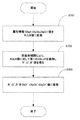
次に、S305において、上述したヒストグラム情報、および顔検出情報を用いて、画像撮影時の露出の適正度判定を行う。図5は本実施例における簡単な適正度判定の例を示している。S501において、顔が検出できたか否かの判定を行う。顔が検出できていれば、S502において顔領域内の輝度色差成分の平均値(ObjY,ObjCb, ObjCr)を算出し、そのうち平均輝度ObjYを、予め定められた露出の適正度合いを決定するための閾値と比較する。比較の結果、顔領域内の平均輝度値が閾値を上回っていれば、適正露出と判断し、下回っていれば、露出不足と判断する。顔が検出できなかった場合、S503において、該ヒストグラムから算出した画像全体の平均輝度値を予め定められた閾値と比較し、閾値を上回っていれば適正露出と判断し、下回っていれば、露出不足と判断する。ここで算出した顔領域内部の平均(ObjY、ObjCb, ObjCr)値や検出した顔領域の画像上での座標位置等は、被写体領域の属性情報として、以降の処理で利用される。 Next, in S305, the appropriateness of exposure at the time of image shooting is determined using the above-described histogram information and face detection information. FIG. 5 shows an example of simple appropriateness determination in the present embodiment. In S501, it is determined whether or not a face has been detected. If the face is detected, the average value (ObjY, ObjCb, ObjCr) of the luminance color difference component in the face area is calculated in S502, and the average luminance ObjY is used to determine the appropriate degree of exposure set in advance. Compare with threshold. If the average luminance value in the face area exceeds the threshold value as a result of the comparison, it is determined that the exposure is appropriate, and if it is below the threshold, it is determined that the exposure is insufficient. If the face could not be detected, in S503, the average luminance value of the entire image calculated from the histogram is compared with a predetermined threshold value, and if it exceeds the threshold value, it is determined that the exposure is appropriate. Judged as insufficient. The average (ObjY, ObjCb, ObjCr) value inside the face area calculated here, the coordinate position of the detected face area on the image, and the like are used in the subsequent processing as attribute information of the subject area.
次に、S306において、カラーバランスの適正度判定を行う。カラーバランスの適正度判定に関しては様々な手法が提案されており、本実施例の中ではどのような手法を用いても構わない。ここでは例として、特許文献1に記載されているような方法によって、カラーバランスの適正度合いを判定すると共に、カラーバランス補正のための回転行列を生成する例を説明する。
Next, in S306, the appropriateness of the color balance is determined. Various methods have been proposed for determining the appropriateness of the color balance, and any method may be used in this embodiment. Here, as an example, an example will be described in which an appropriate degree of color balance is determined and a rotation matrix for color balance correction is generated by a method described in
特許文献1によれば、カラーバランスの適正度合いは画像中のハイライト・シャドーポイントの色差成分によって判定できるとしている。ハイライト・シャドーポイントとは、図4で示した輝度ヒストグラムに対して輝度の低いほうから度数を積算した累積度数分布を算出し、該累積度数が99%のポイントをハイライトポイント、1%のポイントをシャドーポイントと定義している。ハイライト・シャドーポイントと決定された輝度値に該当する画素のみを対象として色差の平均値を算出し、色差が0に近ければカラーバランスは適正、0から遠ざかるほどカラーバランスが不適正であると判定する。不適正と判定された場合には、輝度色差空間において、ハイライト・シャドーポイントの色差を0に近づけるような3×3の回転行列を生成し、該回転行列を対象画素値の輝度色差成分に乗じることで、カラーバランスの補正が可能となる。なお、該回転行列の生成に関する詳細説明は、上記文献に開示されているため、ここでの詳細説明は割愛する。
以上が、本実施例における画像解析部102の説明である。
According to
The above is the description of the image analysis unit 102 in the present embodiment.
(第1の多次元LUT生成部)
図6は、第1の多次元LUT生成部104で実行されるフローチャートを示している。この処理を実行するプログラムは、実行時に二次記憶装置204からRAM202にロードされ、CPU201の制御の下に実行される。本実施例においては、生成するのはRGB各成分が8bit精度の3DLUTであり、格子点間隔は32とする。この場合、全体の格子点数は、9×9×9=729点となる。これら全ての格子点に関して、図6に示した処理を行う。
(First multidimensional LUT generator)
FIG. 6 shows a flowchart executed by the first multidimensional
まず、S601において、カラーバランス補正用回転行列MTX[3][3]を生成する。生成方法は上述した特許文献1に記載されているため、ここでの詳細説明は割愛する。もし、S306におけるカラーバランス適正度判定の結果が、適正であると判定されたなら、MTX[3][3]は以下のような単位行列とする。

次にS602において、注目格子点のRGB値を公知の変換式により、YCbCr成分に変換する。さらに、S603において、該YCbCr値に対して、次式によりMTXを適用し、カラーバランス補正後のY'Cb'Cr'値を算出する。なお、m00〜m22は、S601で生成した回転行列の各要素値を示している。
以上説明したS602〜S604の処理を729点全ての格子点に対して処理することで、第1の3DLUTを生成する(第一の生成)ことができる。
In step S602, the RGB value of the target lattice point is converted into a YCbCr component by a known conversion formula. Further, in S603, MTX is applied to the YCbCr value according to the following equation to calculate a Y′Cb′Cr ′ value after color balance correction. Note that m00 to m22 indicate element values of the rotation matrix generated in S601.
The first 3DLUT can be generated (first generation) by performing the processing of S602 to S604 described above for all the 729 lattice points.
(被写体属性更新部)
被写体属性更新部105は、後述する第2の3DLUTを生成するための準備として、画像解析部102で求めた被写体の属性情報112を更新する。属性情報の更新処理は、図7に示したフローで行われる。属性情報更新部105に入力された被写体の属性情報112(例えば、顔領域内部の平均輝度と平均色差)(ObjY、ObjCb、ObjCr)は、S701において公知の変換式により、RGB値に変換される。S702において、該RGB値に対して、公知の補間方法、ここでは例として四面体補間方法を用いて、前記第1の3DLUTを適用し、その結果、第1の3DLUT適用後のR'G'B'値を得る。さらにS703において、該R'G'B'値を公知の変換式により、ObjY'、ObjCb'、ObjCr'値に変換する(第一の補正)。該ObjY'、ObjCb'、ObjCr'値が更新された属性情報として、次段の処理である第2の多次元LUT生成部106に入力される。
(Subject attribute update unit)
The subject attribute update unit 105 updates the subject attribute information 112 obtained by the image analysis unit 102 as preparation for generating a second 3DLUT described later. The attribute information update process is performed according to the flow shown in FIG. The subject attribute information 112 (for example, average luminance and average color difference inside the face area) (ObjY, ObjCb, ObjCr) input to the attribute information update unit 105 is converted into RGB values by a known conversion formula in S701. . In S702, the first 3DLUT is applied to the RGB values using a known interpolation method, here, for example, a tetrahedral interpolation method. As a result, R′G ′ after the application of the first 3DLUT is applied. Get the B 'value. Further, in S703, the R′G′B ′ value is converted into ObjY ′, ObjCb ′, ObjCr ′ values by a known conversion formula (first correction). The attribute information in which the ObjY ′, ObjCb ′, and ObjCr ′ values are updated is input to the second multi-dimensional
(制御パラメータ生成部)
次に、制御パラメータ生成部103が実行するフローチャートについて説明する。この処理を実行するプログラムは、実行時に二次記憶装置204からRAM202にロードされ、CPU201の制御の下に実行される。制御パラメータは、上述したように、強度調整補間部108の補間強度を制御するためのパラメータである。本実施例では、覆い焼き処理を想定しているため、ここでは制御パラメータとして、入力画像に対する低周波画像、すなわちボケ画像を生成する。
(Control parameter generator)
Next, a flowchart executed by the control parameter generation unit 103 will be described. A program for executing this processing is loaded from the
図8は、制御パラメータ生成部103が実行するフローチャートである。本実施例においては、低周波画像生成方法については特に限定するものではないが、ここでは例として、入力画像を一度縮小して、縮小画像に対してフィルタリング処理を行い、その後元の解像度に戻す処理について説明する。一般的にフィルタリング処理は大量の演算を必要とするため、縮小画像に対して処理することで、その演算コストを低減することができる。 FIG. 8 is a flowchart executed by the control parameter generation unit 103. In this embodiment, the low-frequency image generation method is not particularly limited, but here, as an example, the input image is reduced once, the reduced image is filtered, and then returned to the original resolution. Processing will be described. In general, since filtering processing requires a large amount of computation, the computation cost can be reduced by processing a reduced image.
S801において、入力画像RGB画像に対して、低解像度画像にリサイズする。リサイズ方法は特に限定しないが、処理速度が優先される場合には、最近隣による間引き処理が有効である。 In S801, the input image RGB image is resized to a low resolution image. The resizing method is not particularly limited, but when the processing speed is prioritized, the thinning process by the nearest neighbor is effective.
その後、S802において、リサイズ後のRGB画像データを、公知の変換式により輝度画像に変換する。輝度画像は、各画素あたり輝度情報しか保持しない画像のことであり、モノクロ画像となる。 Thereafter, in S802, the resized RGB image data is converted into a luminance image by a known conversion formula. A luminance image is an image that holds only luminance information for each pixel, and is a monochrome image.
その後、S803において、該輝度画像に対して、公知のフィルタリング処理(平滑化フィルタリング処理)により低周波画像を生成する。フィルタリング処理の方法は特に限定しないが、最も簡単な例は、次式のような平滑化フィルタを、縮小画像中の各画素に施すことが考えられる。
S804において、得られた低周波画像は元の解像度に拡大する。このとき、最近隣補間を用いて拡大処理を行うと、リサイズ後の画像に高周波成分が発生してしまうので、線形補間による拡大処理が望ましい。 In S804, the obtained low-frequency image is enlarged to the original resolution. At this time, if enlargement processing is performed using nearest neighbor interpolation, a high-frequency component is generated in the resized image, so enlargement processing by linear interpolation is desirable.
従来開示されている覆い焼き方法においては、色成分も含んだ低周波画像を生成する例についてのみ言及しているが、本実施例は、上記説明したように低周波画像は輝度成分のみ保持するため、保持に必要なメモリ量が少ないという利点が存在する。 In the conventionally disclosed dodging method, only an example of generating a low-frequency image including a color component is mentioned, but in this embodiment, as described above, the low-frequency image retains only the luminance component. Therefore, there is an advantage that the amount of memory required for holding is small.
(第2の多次元LUT生成部)
図9および図11は、第2の多次元LUT生成部106が実行するフローチャートを示している。
まずS901において、該露出適正度判定の結果に応じて、輝度補正用のトーンカーブTc[256]を生成する。なお、Tc[256]は8bit精度の配列を意味しており、補正前の輝度値に対する補正後の輝度値が格納されている1次元ルックアップテーブルである。
(Second multidimensional LUT generator)
FIG. 9 and FIG. 11 show flowcharts executed by the second multidimensional
First, in S901, a tone curve Tc [256] for luminance correction is generated according to the result of the appropriateness of exposure determination. Note that Tc [256] means an 8-bit precision array, and is a one-dimensional lookup table storing luminance values after correction with respect to luminance values before correction.
図10に、本実施例において被写体領域が露出不足と判定された場合のトーンカーブの生成例を示す。同図において、横軸は補正前の輝度、縦軸は補正後の輝度を示している。同図において、ObjY'は被写体属性更新部105において更新された顔領域内平均輝度を示し、TarYが予め設定されている顔領域の目標輝度値を意味する。トーンカーブTc[256]は、点(ObjY', TarY)を通るような曲線として形成する。本実施例においては、曲線の形成方法については特に限定するものではない。例えば同図のように必ずしも原点(0,0)や白点(255,255)に結ぶ必要もないし、曲線である必要もなく、場合によっては数本の直線によって同様のトーンカーブを形成したとしても構わない。もし、被写体領域が露出不足ではないと判定された場合には、該トーンカーブは、補正前輝度値と補正後輝度値が一致するような直線としてもよい。 FIG. 10 shows an example of tone curve generation when it is determined in this embodiment that the subject area is underexposed. In the figure, the horizontal axis indicates the luminance before correction, and the vertical axis indicates the luminance after correction. In the figure, ObjY ′ indicates the average luminance in the face area updated by the subject attribute update unit 105, and TarY means a target luminance value of the face area that is preset. The tone curve Tc [256] is formed as a curve passing through the point (ObjY ′, TarY). In the present embodiment, the method for forming the curve is not particularly limited. For example, as shown in the figure, it is not always necessary to connect to the origin (0,0) or white point (255,255), it is not necessary to be a curve, and in some cases, a similar tone curve may be formed by several straight lines. Absent. If it is determined that the subject area is not underexposed, the tone curve may be a straight line that matches the pre-correction luminance value and the post-correction luminance value.
被写体補正用トーンカーブが生成されると、次に、S902において、被写体補正用の第2の3DLUTを生成する。図11は、S902の詳細なフローを表している。 After the subject correction tone curve is generated, in step S902, a second 3DLUT for subject correction is generated. FIG. 11 shows a detailed flow of S902.
図11において、まずS1101で、3DLUTの注目格子点のRGB値を公知の変換式により、YCbCr値に変換する。次にS1102において、輝度値Yに対して、以下のようにステップS901で算出したトーンカーブTcを適用し、Y'値を算出する。
Y' = Tc[Y]
In FIG. 11, first, in S1101, the RGB value of the target grid point of 3DLUT is converted into a YCbCr value by a known conversion formula. In step S1102, the tone curve Tc calculated in step S901 is applied to the luminance value Y as follows to calculate the Y ′ value.
Y '= Tc [Y]
次に、S1103で、輝度上昇量に応じた彩度補正を行う。一般的に、輝度色差空間において、輝度のみ上昇させると、その結果得られた画像は彩度が低下した見栄えの良くない画像となってしまう。本実施例においてはこの問題を解決するため、以下の式で表される彩度強調係数Eを算出する。
E = (Y'/Y)×α+β ただし、E は必ず1.0以上
Next, in S1103, saturation correction according to the amount of increase in luminance is performed. Generally, in the luminance color difference space, when only the luminance is increased, the resulting image becomes an unappealing image with reduced saturation. In this embodiment, in order to solve this problem, a saturation emphasis coefficient E represented by the following equation is calculated.
E = (Y '/ Y) x α + β where E is always 1.0 or more
上式において、α、βは任意の係数であり、例としてα=0.4、β=0.6とする。上式は、輝度上昇率(Y'/Y)が1.0に場合には、E=1.0となり、輝度上昇率(Y'/Y)が2.0の場合には、E=1.4となるような式である。Eは必ず1.0以上として、彩度低下は生じないものとする。 In the above equation, α and β are arbitrary coefficients. For example, α = 0.4 and β = 0.6. The above equation is such that E = 1.0 when the luminance increase rate (Y '/ Y) is 1.0, and E = 1.4 when the luminance increase rate (Y' / Y) is 2.0. is there. E is always set to 1.0 or more, and no saturation reduction occurs.
S1103では、以下の式により、注目格子点の彩度補正を行う。
Cb' = Cb × E
Cr' = Cr × E
上記処理により算出された補正後のY'Cb'Cr'値は、S1105において公知の変換式によりR'G'B'に変換され、第2の3DLUTに格納される。
In S1103, the saturation of the target lattice point is corrected by the following equation.
Cb '= Cb × E
Cr '= Cr × E
The corrected Y′Cb′Cr ′ value calculated by the above processing is converted into R′G′B ′ by a known conversion formula in S1105 and stored in the second 3DLUT.
上記S1101〜S1104を全ての格子点に対して処理することにより、第2の3DLUTを生成する(第二の生成)ことができる。 A second 3DLUT can be generated (second generation) by processing S1101 to S1104 with respect to all the lattice points.
(補間部)
入力画像は補間部107に入力され、同部において、公知の補間方法により上記第1の3DLUTが適用される。補間部107では、入力画像の色みが補正される(第二の補正)。本発明においては、補間方法については特に限定するものではなく、公知の四面体補間や、三角柱補間、立方体補間などどのような補間方法を用いても構わない。それぞれの補間方法については、公知文献に数多く記載されているため、ここでの詳細説明は割愛する。
(Interpolation part)
The input image is input to the interpolation unit 107, where the first 3DLUT is applied by a known interpolation method. The interpolation unit 107 corrects the color of the input image (second correction). In the present invention, the interpolation method is not particularly limited, and any interpolation method such as known tetrahedral interpolation, triangular prism interpolation, cube interpolation, or the like may be used. Since each interpolation method is described in large numbers in the publicly known literature, a detailed description thereof is omitted here.
上記補間処理によって、第1の3DLUTが施された画像データ(R',G',B')が次段の強度調整補間部108に入力される。 By the interpolation process, the image data (R ′, G ′, B ′) subjected to the first 3DLUT is input to the intensity adjustment interpolation unit 108 at the next stage.
(強度調整補間部)
強度調整補間部108において、該画像データ(R',G',B')に対して、制御パラメータ113を参照しながら、上記第2の3DLUTを適用してゆく。強度調整補間部108においても、特にその方法を限定するものではなく、公知の補間方法であれば、そのいずれを用いても構わない。
(Intensity adjustment interpolation unit)
The intensity adjustment interpolation unit 108 applies the second 3DLUT to the image data (R ′, G ′, B ′) while referring to the control parameter 113. In the intensity adjustment interpolation unit 108, the method is not particularly limited, and any known interpolation method may be used.
ここでは、強度調整補間部108の強度調整方法について説明する。図12は、強度調整補間部108の処理のフローを表している。 Here, the intensity adjustment method of the intensity adjustment interpolation unit 108 will be described. FIG. 12 shows a processing flow of the intensity adjustment interpolation unit 108.
まず、S1201において、入力画像中の注目画素位置(x,y)に格納されている画素値(R',G',B')に対して、公知の補間方法により第2の3DLUTを適用し、適用後の値(TempR, TempG, TempB)を得る。 First, in S1201, the second 3DLUT is applied to the pixel value (R ′, G ′, B ′) stored at the target pixel position (x, y) in the input image by a known interpolation method. Then, the values after application (TempR, TempG, TempB) are obtained.
次に、S1202において、補間部108に入力された制御パラメータ1206、すなわち低周波輝度画像を参照し、注目画素位置(x,y)に対応する制御パラメータ値、すなわち輝度値BY(x,y)を取得(抽出)する。
Next, in S1202, the
次に、S1203において、次式により、補間強度制御後の画素値(R''、G''、B'')を得る(第三の補正)。
R'' = ( TempR - R' )×(1.0 - BY(x,y)/ 255)+ R'
G'' = ( TempG - G' )×(1.0 - BY(x,y)/ 255)+ G'
B'' = ( TempB - B' )×(1.0 - BY(x,y)/ 255)+ B'
Next, in S1203, pixel values (R ″, G ″, B ″) after interpolation intensity control are obtained by the following equation (third correction).
R '' = (TempR-R ') x (1.0-BY (x, y) / 255) + R'
G '' = (TempG-G ') x (1.0-BY (x, y) / 255) + G'
B '' = (TempB-B ') x (1.0-BY (x, y) / 255) + B'
上式において、BY(x,y)は0〜255の値を持つと想定しているため、BY(x,y)/255は、0.0〜1.0の値を持つことになる。上式を参照するとわかるように、注目画素が暗い領域に含まれる場合には、BY(x,y)が0に近い値となり、その場合、R''=TempRとなって、第2の3DLUTが最大強度で適用されることにある。一方で、注目画素が明るい領域に含まれる場合には、BY(x,y)が255に近い値となり、その場合、R''=R'となり、第2の3DLUTがほとんど適用されないことになる。 In the above formula, it is assumed that BY (x, y) has a value of 0 to 255, so BY (x, y) / 255 has a value of 0.0 to 1.0. As can be seen from the above equation, if the pixel of interest is in a dark area, BY (x, y) is close to 0, in which case R '' = TempR and the second 3DLUT Is applied at maximum intensity. On the other hand, when the target pixel is included in a bright region, BY (x, y) is a value close to 255, in which case R '' = R ', and the second 3DLUT is hardly applied. .
上記のような構成を用いることで、第2の3DLUTの適用強度を制御パラメータ113で制御することが可能となり、画像中の局所的な補正量制御が実現できる。 By using the configuration as described above, the application intensity of the second 3DLUT can be controlled by the control parameter 113, and local correction amount control in the image can be realized.
(以降の処理)
上記補正処理後画像データ(R'',G'',B'')は、色変換部109においてインク色であるCMYK成分に変換され、誤差拡散、ディザ等の擬似階調処理110を経て、プリントエンジン部111で印字媒体上に画像として形成される。
(Subsequent processing)
The corrected image data (R ″, G ″, B ″) is converted into a CMYK component that is an ink color in the color conversion unit 109, and after pseudo gradation processing 110 such as error diffusion and dithering, The print engine unit 111 forms an image on a print medium.
(効果)
以上説明したように、本発明の第1の実施例によれば、複数の補間部を直列接続し、一方の補間部(補間部107)で画像全体に対して均一な補正処理を行い、他方の補間部(強度調整補間部108)でその補間強度を制御パラメータ113で制御する。このことにより、極めて簡単な構成で、従来の課題であった、均一補正と局所補正を同時に行う処理を実現させることができる。
(effect)
As described above, according to the first embodiment of the present invention, a plurality of interpolation units are connected in series, and one interpolation unit (interpolation unit 107) performs uniform correction processing on the entire image. The interpolation strength (intensity adjustment interpolation portion 108) of the control unit 113 controls the interpolation strength with the control parameter 113. As a result, it is possible to realize a process for performing uniform correction and local correction simultaneously, which has been a conventional problem, with an extremely simple configuration.
また、本実施例では、様々な種類の補正処理をあくまで複数の3DLUTを用いて行うことから、課題のところで述べたような、3DLUT方式の利点を最大限利用することができる。 Also, in this embodiment, various types of correction processing are performed using a plurality of 3DLUTs to the maximum, so that the advantages of the 3DLUT method as described in the problem can be utilized to the maximum extent.
また、本実施例では、画像全体を均一補正することに特化した第1の3DLUTを生成し、該第1の3DLUTを用いて被写体の属性情報(例えば、顔の輝度値)を更新する。そして、該更新された被写体情報を元に、今度は被写体を適正化することに特化した第2の3DLUTを生成する。このような構成にすることで、双方の3DLUTの独立性が高くなるため、両者の補正パラメータの設定が、極めて容易に行えるという利点がある。 Further, in this embodiment, a first 3DLUT specialized to uniformly correct the entire image is generated, and subject attribute information (for example, face brightness value) is updated using the first 3DLUT. Then, based on the updated subject information, a second 3DLUT specialized for optimizing the subject is generated. By adopting such a configuration, the independence of both 3DLUTs becomes high, and there is an advantage that the correction parameters for both can be set very easily.
また、上述したように、本実施例においては、制御用パラメータ、すなわち低周波画像は、色成分を保持しない構成となっているため、色成分も保持する従来例と比して、制御用パラメータを保持するためのメモリが少ないという利点も存在する。 In addition, as described above, in this embodiment, the control parameter, that is, the low-frequency image has a configuration that does not hold the color component. Therefore, the control parameter is different from the conventional example that also holds the color component. There is also an advantage that there is little memory to hold the.
また、本実施例においては、第1の3DLUTは、画像全体のカラーバランス補正のみを取り上げて説明したが、本実施例はこれに限定されるものではない。例えば、第1の3DLUTでは、画像全体が露出不足の場合、レベル補正処理を組み込み、カラーバランスと全体の明るさを明るくした後、さらに被写体の明るさを適正化するような第2の3DLUTを生成することも考えられる。 In the present embodiment, the first 3DLUT has been described by taking up only the color balance correction of the entire image, but the present embodiment is not limited to this. For example, in the first 3DLUT, if the entire image is underexposed, level correction processing is incorporated, the color balance and overall brightness are increased, and then the second 3DLUT that optimizes the brightness of the subject is added. It can also be generated.
このように、画像全体が露出不足で被写体の顔も暗い場合、従来のように1つの3DLUTのみで、被写体の明るさを適正化しようとすると問題が発生する場合がある。すなわち、図13に示したように、輝度補正トーンカーブの暗部側の傾きが急峻になりすぎて、暗部でトーンジャンプ等の画像不具合が発生する場合がある。また、トーンカーブ中間調のコントラストの傾きを一定以上保とうとすると、1302に示したように、白トビ領域が拡大するという不具合もある。この点、本実施例で示したような複数の3DLUTで分担して輝度補正を行えば、上記不具合が発生しにくいという格別な利点が存在する。 As described above, when the entire image is underexposed and the face of the subject is dark, there may be a problem when trying to optimize the brightness of the subject using only one 3DLUT as in the prior art. That is, as shown in FIG. 13, the darkness side inclination of the luminance correction tone curve may be too steep, and image defects such as tone jump may occur in the dark portion. In addition, if an attempt is made to maintain the contrast gradient of the tone curve halftone above a certain level, there is also a problem that the white stripe region is enlarged as indicated by 1302. In this regard, there is a special advantage that the above-mentioned problem is unlikely to occur when luminance correction is performed by sharing a plurality of 3DLUTs as shown in the present embodiment.
以上が第1の実施例の説明であるが、本発明は上記実施例に限定されるものではない。例えば、3DLUTの格子点数は729点に限定されるものではなく、それ以上でも以下でも構わない。 The above is the description of the first embodiment, but the present invention is not limited to the above embodiment. For example, the number of grid points of 3DLUT is not limited to 729, and it may be more or less.
また、LUTを簡単のため3次元に固定して説明を行ったが、例えばCMYK4成分に対して同様の処理を行うことも考えられ、この場合には4次元LUTを生成することになる。また、本実施例においては、簡単のため輝度色差空間をYcbCr空間に限定して説明したが、他の色空間、例えばCIE Labであってもよい。また、本実施例においては、簡単のため、補間部2個に限定して説明したが、必要に応じてさらに複数個の補間部を直列接続しても構わない。また、本実施例においては、該補間部はハードウェア200に搭載されているCPUによるソフト処理を前提に説明を行ったが、必要に応じて同部のみをハードウェア回路としたとしても、本発明の目的を達成することができる。また、本実施例においては、補間部に入出力される画像データは、画像一面分のフレームを想定していたが、例えば、補間部への入出力は画素単位でもよいし、所定数のラインをまとめたバンド単位でもよい。
In addition, the LUT is described as being fixed in three dimensions for the sake of simplicity. For example, the same processing may be performed on the CMYK4 component. In this case, a four-dimensional LUT is generated. In the present embodiment, the luminance color difference space is limited to the YcbCr space for the sake of simplicity. However, another color space such as CIE Lab may be used. In the present embodiment, for the sake of simplicity, the description is limited to two interpolation units. However, a plurality of interpolation units may be connected in series as necessary. Further, in this embodiment, the interpolation unit has been described on the assumption that the software processing by the CPU mounted on the
(第2の実施例)
第1の実施例においては、第1の3DLUTを施した後の被写体属性情報(ObjY', ObjCb', ObjCr')を用いて、顔の平均輝度値ObjY'が目標輝度値TarYに補正されるようなトーンカーブを用いて第2の3DLUTを生成した。
(Second embodiment)
In the first embodiment, the face average luminance value ObjY ′ is corrected to the target luminance value TarY using the subject attribute information (ObjY ′, ObjCb ′, ObjCr ′) after applying the first 3DLUT. A second 3DLUT was generated using such a tone curve.
ただし、この3DLUTを用いて、第1の実施例に記載されたような強度調整補間部108で補正を行っても、顔の平均輝度値が正しく目標輝度値TarYにはならないという問題がある。 However, there is a problem that the average luminance value of the face does not correctly become the target luminance value TarY even if correction is performed by the intensity adjustment interpolation unit 108 described in the first embodiment using this 3DLUT.
例えば、ObjY'=60、TarY=140であると仮定する。このとき強度調整補間部108において、第2の3DLUTが最大強度で適用されれば、顔領域は正しく目標輝度値Tar=140に変換されることになる。しかし、実際には第1の実施例で説明したように、強度調整補間部108は制御パラメータ113、すなわち低周波輝度画像(低解像度画像)でその適用強度を制御することになる。そのため、例えば、制御パラメータ113が示す低周波輝度画像(ボケ画像)における顔領域の平均輝度値が50だった場合、強度調整補間部108の制御式によれば、第2の3DLUTの適用強度は1.0-(50/255)=0.8となる。すなわちおよそ80%の適用強度となる。 For example, assume that ObjY ′ = 60 and TarY = 140. At this time, if the second 3DLUT is applied at the maximum intensity in the intensity adjustment interpolation unit 108, the face area is correctly converted to the target luminance value Tar = 140. However, actually, as described in the first embodiment, the intensity adjustment interpolating unit 108 controls the applied intensity with the control parameter 113, that is, the low frequency luminance image (low resolution image). Therefore, for example, when the average luminance value of the face area in the low-frequency luminance image (blurred image) indicated by the control parameter 113 is 50, according to the control expression of the intensity adjustment interpolation unit 108, the application intensity of the second 3DLUT is 1.0- (50/255) = 0.8. That is, the applied strength is approximately 80%.
すなわち、輝度値60だったObjY'は、124までしか補正されないことになる。 That is, ObjY ′ having a luminance value of 60 is corrected only up to 124.
本実施例では本問題を鑑み、制御パラメータで第2の3DLUTの適用強度を制御した際においても、被写体の明るさを目標の明るさに適切に制御する画像処理装置について説明する。 In this embodiment, in view of this problem, an image processing apparatus that appropriately controls the brightness of a subject to a target brightness even when the application intensity of the second 3DLUT is controlled by a control parameter will be described.
図14は、本実施例における処理のブロック図を示している。第1の実施例と異なる点は、制御パラメータ生成部1408で生成した制御パラメータ1413が、第2の多次元LUT生成部1405に入力されている点である。
FIG. 14 shows a block diagram of processing in the present embodiment. The difference from the first embodiment is that the control parameter 1413 generated by the control
図15は、本実施例における第2の多次元LUT生成部1405が実行するフローチャートを示している。 FIG. 15 shows a flowchart executed by the second multidimensional LUT generator 1405 in the present embodiment.
S1501において、第1の実施例と同様に、被写体補正用のトーンカーブを生成する。 In S1501, as in the first embodiment, a tone curve for subject correction is generated.
次に、S1502において、同部に入力された制御パラメータ、すなわち低周波輝度画像1506上において、被写体領域の平均輝度FBYを算出する。平均輝度は、被写体属性情報1505に含まれる画像上での被写体領域の座標位置を元に算出することができる。 Next, in S1502, the average luminance FBY of the subject area is calculated on the control parameter input to the same part, that is, on the low-frequency luminance image 1506. The average luminance can be calculated based on the coordinate position of the subject area on the image included in the subject attribute information 1505.
次に、S1503において、該トーンカーブを、前記FBY値を用いて修正する。
この修正ステップを、図16を用いて説明する。
In step S1503, the tone curve is corrected using the FBY value.
This correction step will be described with reference to FIG.
同図において、Tc[256]が、第1の実施例で説明した被写体補正用トーンカーブである。該トーンカーブ自身は更新後の被写体輝度値であるObjY'値を目標輝度値TarYに補正することが可能であるが、上述したように、制御パラメータとの関係により、最終的にはTarYに到達しない可能性が高い。 In the figure, Tc [256] is the tone curve for subject correction described in the first embodiment. The tone curve itself can correct the updated subject brightness value ObjY 'value to the target brightness value TarY, but eventually reaches TarY due to the relationship with the control parameters as described above. There is a high possibility of not.
本実施例では、以下の式によりTarY'値を算出し、該TarY'値を経由するトーンカーブTc'[256]を用いて、第2の3DLUTを生成することとする。
![]()
![]()
上式より、
上式より、
Tc'[k] = Tc[k]×(TarY'/TarY) k= 0〜255
From the above formula,
Tc '[k] = Tc [k] x (TarY' / TarY) k = 0 to 255
上式は、FBYが0であれば、TarY' = TarYであるし、FBYが128であれば、TarY'=2×TarY-ObjY'となることを示している。Tc'[k]は、Tc[k]に倍率(TarY'/TarY)を乗じることにより、図16に示すようなトーンカーブ1601を生成することができる。 The above equation shows that if FBY is 0, TarY ′ = TarY, and if FBY is 128, TarY ′ = 2 × TarY−ObjY ′. Tc ′ [k] can generate a tone curve 1601 as shown in FIG. 16 by multiplying Tc [k] by a magnification (TarY ′ / TarY).
上述した例について具体的に説明すると、ObjY'=60、TarY=140であり、かつFYB=51であったと仮定する。 The above example will be specifically described. It is assumed that ObjY ′ = 60, TarY = 140, and FYB = 51.
この場合、TarY'=160となる。FYB=51の場合、第2の3DLUTの効き率は80%となるため、最終的な顔平均値は、(160-60)×0.8+60=140となり、当初の目標輝度値に到達することになる。 In this case, TarY ′ = 160. When FYB = 51, the effectiveness rate of the second 3DLUT is 80%, so the final average face value is (160-60) x 0.8 + 60 = 140, and the initial target brightness value must be reached. become.
以降の処理は第1の実施例と同様のため、ここでの詳細な処理は割愛する。 Since the subsequent processing is the same as that of the first embodiment, detailed processing is omitted here.
以上説明したように、本実施例によれば、一度生成した被写体補正用トーンカーブを、制御用パラメータの被写体領域平均値を用いて修正することにより、最終的な出力を、画質目標として想定通りの結果とすることが可能となる。 As described above, according to the present embodiment, by correcting the once generated subject correction tone curve using the subject region average value of the control parameter, the final output is set as an image quality target as expected. It is possible to obtain the result of
なお本実施例においては、第1の実施例を踏襲し、被写体補正用トーンカーブTc[256]を算出した後、同カーブを修正する方法について説明したが、本発明はこれに限定されるものではない。例えば、Tcを算出する際に、予めTarY'を算出し、点(ObjY', TarY')を通過するトーンカーブを生成し、該トーンカーブをTcとしてもよい。 In this embodiment, the method of correcting the curve after calculating the subject correction tone curve Tc [256] has been described following the first embodiment, but the present invention is not limited to this. is not. For example, when calculating Tc, TarY ′ is calculated in advance, a tone curve passing through the point (ObjY ′, TarY ′) is generated, and the tone curve may be set as Tc.
(第3の実施例)
第1の実施例では、簡単のために2つの補間部に入力される2つの3DLUTは、同じ729格子点で、かつRGB各成分が8bit精度の3DLUTを想定して説明を行ったが、本発明はこれに限定されるものではない。
(Third embodiment)
In the first embodiment, for the sake of simplicity, two 3DLUTs input to two interpolation units have been described assuming that 3DLUTs having the same 729 grid points and RGB components of 8 bits are accurate. The invention is not limited to this.
例えば、それぞれの3DLUTが担う補正の種類・性格によっては、それぞれの格子点数やビット精度が異なっていた方が、全体システムとして効率的に動作する場合がある。本実施例では、このことについて説明する。 For example, depending on the type and nature of correction carried out by each 3DLUT, if the number of grid points and the bit accuracy are different, the entire system may operate more efficiently. In the present embodiment, this will be described.
図17は、本実施例における処理のブロック図を示している。第1の実施例と異なる点は、1701において生成する3DLUTが各成分8bit、格子点数729点であり、1702において生成する3DLUTが各成分10bit、格子点数4096点となっている。この理由について以下に説明する。 FIG. 17 shows a block diagram of processing in the present embodiment. The difference from the first embodiment is that the 3DLUT generated in 1701 has 8 bits for each component and 729 grid points, and the 3DLUT generated in 1702 has 10 bits for each component and 4096 grid points. The reason for this will be described below.
上述したように、第1の3DLUTは画像全体を適正化することに特化するという性格を持っているため、一般的にRGB色空間の中で非線形な挙動を起こす可能性は低くなる。例えば、第1の実施例で説明したような回転行列を用いた色かぶり補正も線形変換であるし、レベル補正や彩度強調についても、極端な非線形性を保持するものではない。このような変換を行う際に用いる3DLUTは、その格子点数やビット精度が少なかったとしても、補間後の画素値は、目標値に対して十分な精度を保つことができる。 As described above, since the first 3DLUT has a characteristic of specializing in optimizing the entire image, the possibility of causing nonlinear behavior in the RGB color space is generally low. For example, the color cast correction using the rotation matrix as described in the first embodiment is also linear conversion, and the level correction and saturation enhancement do not hold extreme nonlinearity. Even if the 3DLUT used for such conversion has a small number of grid points and bit accuracy, the pixel value after interpolation can maintain sufficient accuracy with respect to the target value.
一方で、第2の3DLUTは、画像全体ではなく、被写体を適正化することに特化するという性格を持っているため、例えば階調補正のためのトーンカーブが急峻であるため、暗部側においてトーンジャンプなどの画像弊害を発生することが考えられる。そのためには、例えば第2の3DLUTの各RGB成分値を8bitではなく10bitで保持することにより、より階調性を高めることができ、上記画像弊害を起こりにくくすることができる。また、被写体が人物である場合、例えば肌色領域のみを所望の彩度に修正するといった非線形処理が要求される場合がある。この際に、本実施例のように第2の3DLUTの格子点数を、729点よりも多い4096点用意して、各格子点間の距離を短くすることで、該非線形処理に対しても精度の高い補正処理を行うことができる。 On the other hand, the second 3DLUT has a character that specializes in optimizing the subject, not the entire image. For example, since the tone curve for tone correction is steep, It can be considered that image adverse effects such as tone jump occur. For this purpose, for example, by holding each RGB component value of the second 3DLUT at 10 bits instead of 8 bits, the gradation can be further improved, and the above-described image adverse effects can be made difficult to occur. Further, when the subject is a person, for example, a non-linear process such as correcting only the skin color region to a desired saturation may be required. At this time, as in the present embodiment, the number of grid points of the second 3DLUT is prepared as 4096 points larger than 729 points, and the distance between each grid point is shortened, so that the accuracy can be improved even for the nonlinear processing. High correction processing can be performed.
その他の処理は第1の実施例と同様であるため、ここでの詳細な説明は割愛する。 Since other processes are the same as those of the first embodiment, a detailed description thereof is omitted here.
以上説明したように、本実施例によれば、複数の多次元LUTを保持する画像処理装置において、それぞれのLUTが担う処理の内容に応じて、多次元LUTの格子点数やビット精度を相異なるものとする。これにより、例えばLUT保持のために使用する全体のRAM容量を削減することが可能となる。例えば、RGB各成分16bitで格子点数4096のLUTを2個保持する場合には、48KBのRAMが必要となる。一方で、1つはRGB成分各8bitで格子点数729のLUTとすることにより、LUTを保持するRAM容量は26KBとなり、上記に対して約46%の削減となる。 As described above, according to the present embodiment, in the image processing apparatus that holds a plurality of multi-dimensional LUTs, the number of lattice points and bit accuracy of the multi-dimensional LUTs are different depending on the content of processing performed by each LUT. Shall. Thereby, for example, it is possible to reduce the total RAM capacity used for holding the LUT. For example, when two LUTs each having 16 bits of RGB and 4096 grid points are held, 48 KB of RAM is required. On the other hand, by using an LUT with 8 bits for each RGB component and 729 grid points, the RAM capacity for holding the LUT is 26 KB, which is a reduction of about 46% compared to the above.
また、補間部1701,1702をハードウェア回路として実装する場合においても、双方16bit精度の補間処理を実装するより、一方を8bit精度とすることで、補間回路全体の規模を縮小させ、かつ同等の出力結果が得られるという効果も存在する。 In addition, even when the interpolation units 1701 and 1702 are implemented as hardware circuits, both the 16-bit precision interpolation processing is implemented, and one of them is 8-bit precision, thereby reducing the overall scale of the interpolation circuit and equivalent. There is also an effect that an output result can be obtained.
なお、本実施例においては、簡単のため、補間回路は2つで、双方の格子点数、ビット精度を限定して説明したが、本発明はこれに限定されるものではない。補間回路の数、格子点数、ビット数がいかなる組み合わせであったとしても、本発明の効果を実現できるものであれば、本発明の範疇に含まれる。 In the present embodiment, for the sake of simplicity, there are two interpolation circuits and the number of grid points and the bit precision of both are limited, but the present invention is not limited to this. Any combination of the number of interpolation circuits, the number of grid points, and the number of bits is included in the scope of the present invention as long as the effects of the present invention can be realized.
以上が第3の実施例の説明である。 The above is the description of the third embodiment.
(その他の実施例)
以上の実施例では、簡単のためRGB成分を保持する3DLUTを例に説明を行ったが、本発明はこれに限定されるものではない。例えば、輝度色差成分であるYCbCr値の3DLUTで構成することも可能であるし、インク色成分であるCMYK4次元LUTでも同様に構成することは可能であり、さらなる多次元LUTを想定した場合にも、本発明の範疇に含まれることは言うまでもない。
(Other examples)
In the above embodiment, for the sake of simplicity, the description has been given by taking 3DLUT holding RGB components as an example, but the present invention is not limited to this. For example, it can be configured with 3DLUTs of YCbCr values that are luminance color difference components, and can be similarly configured with CMYK four-dimensional LUTs that are ink color components, even when further multidimensional LUTs are assumed. Needless to say, these are included in the scope of the present invention.
また、以上の実施例では、簡単のため、補間方法として四面体補間を例に挙げて説明を行ったが、本発明はこれに限定されるものではない。例えば、公知の立方体補間や三角柱補間など、他のいかなる補間方法を用いたとしても、本発明の範疇に含まれることは言うまでもない。 In the above embodiments, for the sake of simplicity, description has been made by taking tetrahedral interpolation as an example of the interpolation method, but the present invention is not limited to this. Needless to say, any other interpolation method such as known cubic interpolation or triangular prism interpolation is included in the scope of the present invention.
また、以上の実施例では、簡単のため、被写体は人物顔領域であり、その数は1つを前提に説明を行ったが、本発明はこれに限定されるものではない。例えば、被写体は人間の顔以外のオブジェクト(例えば動物や建物)であっても構わないし、その数は一つとは限らない。もし複数あれば、そのうちの特徴的な1つに限定して処理を行ってもよいし、全ての被写体の属性情報を平均して処理を行っても構わない。 In the above embodiment, for the sake of simplicity, the subject is a human face region and the number of subjects is one. However, the present invention is not limited to this. For example, the subject may be an object (for example, an animal or a building) other than a human face, and the number is not limited to one. If there are a plurality, the processing may be limited to one characteristic of them, or the processing may be performed by averaging the attribute information of all subjects.
また、本発明は簡単のため、局所的画像補正として覆い焼き処理を代表例として説明を行ってきたが、本発明はこれに限定されるものではない。例えば、青空領域を検出し、該領域のみ色相・彩度を好ましい方向に補正する処理と局所的補正と考えたとしても、本発明の構成によって、極めて効率的に実現することが可能となる。 Further, for the sake of simplicity, the dodging process has been described as a representative example as local image correction, but the present invention is not limited to this. For example, even if the blue sky region is detected and only the region is considered to be a process of correcting the hue / saturation in a preferable direction and local correction, the configuration of the present invention makes it possible to realize it extremely efficiently.
また、本発明は、複数の機器(例えばホストコンピュータ、インタフェイス機器、リーダ、プリンタ等)から構成されるシステムに適用しても、一つの機器からなる装置(例えば、複写機、ファクシミリ装置等)に適用しても良い。 In addition, the present invention can be applied to a system composed of a plurality of devices (for example, a host computer, interface device, reader, printer, etc.), or a device (for example, a copier, a facsimile device, etc.) composed of a single device. You may apply to.
また、本発明の目的は、以下によっても達成できる。まず、前述した実施形態の機能を実現するソフトウエアのプログラムコードを記録した記憶媒体(または記録媒体)を、システムあるいは装置に供給する。次に、そのシステムあるいは装置のコンピュータ(またはCPUやMPU)が記憶媒体に格納されたプログラムコードを読み出し実行すればよい。この場合、記憶媒体から読み出されたプログラムコード自体が前述した実施形態の機能を実現することになり、そのプログラムコードを記憶した記憶媒体は本発明を構成することになる。また、コンピュータが読み出したプログラムコードを実行することにより、前述した実施形態の機能が実現されるだけではない。例えば、そのプログラムコードの指示に基づき、コンピュータ上で稼働しているオペレーティングシステム(OS)などが実際の処理の一部または全部を行い、その処理によって前述した実施形態の機能が実現される場合も含まれることは言うまでもない。 The object of the present invention can also be achieved by the following. First, a storage medium (or recording medium) that records software program codes that implement the functions of the above-described embodiments is supplied to a system or apparatus. Next, the computer (or CPU or MPU) of the system or apparatus may read and execute the program code stored in the storage medium. In this case, the program code itself read from the storage medium realizes the functions of the above-described embodiments, and the storage medium storing the program code constitutes the present invention. In addition, the functions of the above-described embodiments are not only realized by executing the program code read by the computer. For example, an operating system (OS) running on a computer performs part or all of actual processing based on an instruction of the program code, and the functions of the above-described embodiments may be realized by the processing. Needless to say, it is included.
さらに、まず、記憶媒体から読み出されたプログラムコードが、コンピュータに挿入された機能拡張カードやコンピュータに接続された機能拡張ユニットに備わるメモリに書き込まれる。その後、該プログラムコードの指示に基づき、その機能拡張カードや機能拡張ユニットに備わるCPUなどが実際の処理の一部または全部を行い、その処理によって前述した実施形態の機能が実現される場合も含まれることは言うまでもない。 Further, first, the program code read from the storage medium is written in a memory provided in a function expansion card inserted into the computer or a function expansion unit connected to the computer. Thereafter, the CPU of the function expansion card or function expansion unit performs part or all of the actual processing based on the instruction of the program code, and the function of the above-described embodiment is realized by the processing. Needless to say.
101・・・画像読み込み部
102・・・画像解析部
103・・・制御パラメータ生成部
104・・・第1の多次元LUT生成部
105・・・被写体属性更新部
106・・・第2の多次元LUT生成部
107・・・補間部
108・・・強度調整補間部
109・・・色変換部
110・・・擬似階調処理部
111・・・プリンタエンジン
112・・・被写体属性情報
113・・・制御パラメータ
101 ・ ・ ・ Image reading part
102 ... Image analysis unit
103 ... Control parameter generator
104 ... 1st multidimensional LUT generator
105 ... Subject attribute update section
106 ・ ・ ・ Second multidimensional LUT generator
107 ... Interpolator
108 ・ ・ ・ Intensity adjustment interpolation unit
109 ... color converter
110 ... Pseudo gradation processing part
111 ・ ・ ・ Printer engine
112 ・ ・ ・ Subject attribute information
113 ・ ・ ・ Control parameters
Claims (29)
前記画像に含まれる特定オブジェクトの属性情報を前記第1のルックアップテーブルを用いて更新する更新手段と、
前記更新手段によって更新された属性情報に基づいて前記特定オブジェクトを補正するための第2のルックアップテーブルを生成する第2の生成手段と、
前記生成された第1および第2のルックアップテーブルを用いて、前記画像を補正する補正手段とを有し、
前記補正手段は、前記画像の輝度情報に基づき、前記第2のルックアップテーブルを用いて補正する量を制御することを特徴とする画像処理装置。 First generation means for generating a first look-up table for correcting the image based on a feature amount of the image;
Updating means for updating attribute information of a specific object included in the image using the first lookup table;
Second generation means for generating a second lookup table for correcting the specific object based on the attribute information updated by the update means;
Using the first and second look-up table pre-SL generated, and a correction means for correcting the image,
The image processing apparatus, wherein the correction unit controls an amount of correction using the second lookup table based on luminance information of the image.
前記画像に含まれる特定オブジェクトの属性情報を前記第1のルックアップテーブルを用いて更新する更新工程と、
前記更新工程によって更新された属性情報に基づいて前記特定オブジェクトを補正するための第2のルックアップテーブルを生成する第2の生成工程と、
前記生成された第1および第2のルックアップテーブルを用いて、前記画像を補正する補正工程とを有し、
前記補正工程は、前記画像の輝度情報に基づき、前記第2のルックアップテーブルを用いて補正する量を制御することを特徴とする画像処理方法。 A first generation step of generating a first lookup table for correcting the image based on a feature amount of the image;
An update step of updating attribute information of the specific object included in the image using the first lookup table;
A second generation step of generating a second lookup table for correcting the specific object based on the attribute information updated by the update step;
Using the first and second look-up table pre-SL generated, and a correction step of correcting the image,
The image processing method according to claim 1, wherein the correction step controls an amount of correction using the second lookup table based on luminance information of the image.
Priority Applications (5)
| Application Number | Priority Date | Filing Date | Title |
|---|---|---|---|
| JP2009128568A JP5300595B2 (en) | 2009-05-28 | 2009-05-28 | Image processing apparatus and method, and computer program |
| US12/778,917 US9055263B2 (en) | 2009-05-28 | 2010-05-12 | Apparatus, method and computer program for correcting an image using lookup tables generated by inputted image analysis |
| EP10163948.2A EP2257038B1 (en) | 2009-05-28 | 2010-05-26 | Image processing apparatus, image processing method, and computer program |
| KR1020100049421A KR101248858B1 (en) | 2009-05-28 | 2010-05-27 | Image processing apparatus and image processing method |
| CN201010188576.7A CN101902550B (en) | 2009-05-28 | 2010-05-28 | Image processing apparatus, image processing method |
Applications Claiming Priority (1)
| Application Number | Priority Date | Filing Date | Title |
|---|---|---|---|
| JP2009128568A JP5300595B2 (en) | 2009-05-28 | 2009-05-28 | Image processing apparatus and method, and computer program |
Related Child Applications (1)
| Application Number | Title | Priority Date | Filing Date |
|---|---|---|---|
| JP2013125516A Division JP5632937B2 (en) | 2013-06-14 | 2013-06-14 | Image processing apparatus and method, and computer program |
Publications (3)
| Publication Number | Publication Date |
|---|---|
| JP2010278708A JP2010278708A (en) | 2010-12-09 |
| JP2010278708A5 JP2010278708A5 (en) | 2012-07-05 |
| JP5300595B2 true JP5300595B2 (en) | 2013-09-25 |
Family
ID=42542953
Family Applications (1)
| Application Number | Title | Priority Date | Filing Date |
|---|---|---|---|
| JP2009128568A Active JP5300595B2 (en) | 2009-05-28 | 2009-05-28 | Image processing apparatus and method, and computer program |
Country Status (5)
| Country | Link |
|---|---|
| US (1) | US9055263B2 (en) |
| EP (1) | EP2257038B1 (en) |
| JP (1) | JP5300595B2 (en) |
| KR (1) | KR101248858B1 (en) |
| CN (1) | CN101902550B (en) |
Families Citing this family (17)
| Publication number | Priority date | Publication date | Assignee | Title |
|---|---|---|---|---|
| KR20130098675A (en) * | 2012-02-28 | 2013-09-05 | 삼성전자주식회사 | Face detection processing circuit and image pick-up device including the same |
| JP5986877B2 (en) * | 2012-10-17 | 2016-09-06 | 日立マクセル株式会社 | Image transmission system |
| JP6478487B2 (en) | 2014-06-13 | 2019-03-06 | キヤノン株式会社 | Information processing apparatus, information processing method, and program |
| JP6378645B2 (en) | 2014-06-13 | 2018-08-22 | キヤノン株式会社 | Information processing apparatus, control method, and program |
| JP6008897B2 (en) | 2014-06-13 | 2016-10-19 | キヤノン株式会社 | Apparatus, method, and program |
| JP6386803B2 (en) | 2014-06-13 | 2018-09-05 | キヤノン株式会社 | Apparatus, method, and program |
| JP6438218B2 (en) | 2014-06-13 | 2018-12-12 | キヤノン株式会社 | Apparatus, method, and program |
| JP6138088B2 (en) | 2014-06-30 | 2017-05-31 | キヤノン株式会社 | Information processing apparatus, control method, and software program |
| JP6463914B2 (en) | 2014-06-30 | 2019-02-06 | キヤノン株式会社 | Information processing apparatus, processing method, and program |
| JP6381319B2 (en) | 2014-06-30 | 2018-08-29 | キヤノン株式会社 | Information processing apparatus, processing method, and program |
| JP6486055B2 (en) * | 2014-10-09 | 2019-03-20 | キヤノン株式会社 | Imaging apparatus, control method therefor, and program |
| US9602739B1 (en) | 2016-10-23 | 2017-03-21 | Visual Supply Company | Lookup table interpolation in a film emulation camera system |
| CN108877735B (en) * | 2017-05-12 | 2021-01-26 | 京东方科技集团股份有限公司 | Gray scale brightness adjusting method and adjusting device of display equipment |
| CN107993269A (en) * | 2017-10-25 | 2018-05-04 | 维沃移动通信有限公司 | A kind of image processing method and mobile terminal |
| JP7034742B2 (en) * | 2018-01-29 | 2022-03-14 | キヤノン株式会社 | Image forming device, its method and program |
| CN109034142A (en) * | 2018-09-29 | 2018-12-18 | 广州微印信息科技有限公司 | A kind of photo processing method based on image recognition |
| CN113034412B (en) * | 2021-02-25 | 2024-04-19 | 北京达佳互联信息技术有限公司 | Video processing method and device |
Family Cites Families (24)
| Publication number | Priority date | Publication date | Assignee | Title |
|---|---|---|---|---|
| JP3568279B2 (en) * | 1995-06-30 | 2004-09-22 | 富士写真フイルム株式会社 | Image reproducing method and apparatus |
| JPH1079857A (en) | 1996-09-05 | 1998-03-24 | Fuji Photo Film Co Ltd | Conversion method for image information and image recording device |
| JP3408770B2 (en) * | 1998-03-04 | 2003-05-19 | 富士写真フイルム株式会社 | Image processing device |
| JP3950551B2 (en) | 1998-06-24 | 2007-08-01 | キヤノン株式会社 | Image processing method, apparatus, and recording medium |
| JP4194133B2 (en) * | 1998-06-24 | 2008-12-10 | キヤノン株式会社 | Image processing method and apparatus, and storage medium |
| US7440612B2 (en) * | 1998-11-13 | 2008-10-21 | Sony Corporation | Image processing apparatus and method capable of correcting gradation of image data |
| JP3233114B2 (en) | 1998-11-13 | 2001-11-26 | ソニー株式会社 | Image processing apparatus and image processing method |
| JP2001069352A (en) * | 1999-08-27 | 2001-03-16 | Canon Inc | Picture processor and its method |
| JP4081219B2 (en) * | 2000-04-17 | 2008-04-23 | 富士フイルム株式会社 | Image processing method and image processing apparatus |
| JP3514257B2 (en) * | 2002-05-20 | 2004-03-31 | セイコーエプソン株式会社 | Image processing system, projector, image processing method, program, and information storage medium |
| JP4461789B2 (en) * | 2003-03-20 | 2010-05-12 | オムロン株式会社 | Image processing device |
| JP3880553B2 (en) * | 2003-07-31 | 2007-02-14 | キヤノン株式会社 | Image processing method and apparatus |
| GB0408557D0 (en) * | 2004-04-16 | 2004-05-19 | Pandora Int Ltd | Image processing |
| US7406210B2 (en) * | 2004-06-28 | 2008-07-29 | Xerox Corporation | Darkness control using pattern matching |
| JP2006146646A (en) | 2004-11-22 | 2006-06-08 | Noritsu Koki Co Ltd | Method and apparatus for processing photographic image |
| JP4455307B2 (en) | 2004-12-14 | 2010-04-21 | キヤノン株式会社 | Image processing apparatus and method, and memory medium |
| JP4304623B2 (en) | 2005-06-01 | 2009-07-29 | ソニー株式会社 | Imaging apparatus and method of processing imaging result in imaging apparatus |
| WO2007142624A1 (en) * | 2006-06-02 | 2007-12-13 | Thomson Licensing | Converting a colorimetric transform from an input color space to an output color space |
| JP2008085980A (en) * | 2006-08-31 | 2008-04-10 | Sony Corp | Color conversion device, emulation method, formation method of three-dimension lookup table, and image processor |
| US8334910B2 (en) * | 2007-02-09 | 2012-12-18 | Canon Kabushiki Kaisha | Image capturing apparatus, information processing apparatus, and control methods thereof |
| US8213695B2 (en) * | 2007-03-07 | 2012-07-03 | University Of Houston | Device and software for screening the skin |
| JP5032911B2 (en) * | 2007-07-31 | 2012-09-26 | キヤノン株式会社 | Image processing apparatus and image processing method |
| JP4906627B2 (en) * | 2007-07-31 | 2012-03-28 | キヤノン株式会社 | Image processing apparatus, image processing method, computer program, and storage medium |
| JP5116393B2 (en) * | 2007-07-31 | 2013-01-09 | キヤノン株式会社 | Image processing apparatus and image processing method |
-
2009
- 2009-05-28 JP JP2009128568A patent/JP5300595B2/en active Active
-
2010
- 2010-05-12 US US12/778,917 patent/US9055263B2/en active Active
- 2010-05-26 EP EP10163948.2A patent/EP2257038B1/en active Active
- 2010-05-27 KR KR1020100049421A patent/KR101248858B1/en active IP Right Grant
- 2010-05-28 CN CN201010188576.7A patent/CN101902550B/en active Active
Also Published As
| Publication number | Publication date |
|---|---|
| US9055263B2 (en) | 2015-06-09 |
| EP2257038A3 (en) | 2013-03-13 |
| KR101248858B1 (en) | 2013-03-29 |
| JP2010278708A (en) | 2010-12-09 |
| CN101902550A (en) | 2010-12-01 |
| US20100303351A1 (en) | 2010-12-02 |
| EP2257038A2 (en) | 2010-12-01 |
| EP2257038B1 (en) | 2016-10-19 |
| KR20100129194A (en) | 2010-12-08 |
| CN101902550B (en) | 2014-03-26 |
Similar Documents
| Publication | Publication Date | Title |
|---|---|---|
| JP5300595B2 (en) | Image processing apparatus and method, and computer program | |
| US8929681B2 (en) | Image processing apparatus and image processing method | |
| US8290259B2 (en) | Device adaptively switching color emphasis processing for image | |
| JP3520550B2 (en) | Color image processing system and its data correction method | |
| EP3588930B1 (en) | Image processing apparatus, image processing method, and program | |
| JP2001313844A (en) | Method and device for executing local color correction | |
| US7920752B2 (en) | Image processing device that quickly performs retinex process | |
| JP5157678B2 (en) | Photo image processing method, photo image processing program, and photo image processing apparatus | |
| US7912308B2 (en) | Image processing device that quickly performs retinex process | |
| US7689065B2 (en) | Image processing method and apparatus for suppressing positional shift image degradation | |
| JP4208767B2 (en) | Image processing apparatus and image processing method | |
| JPH11120325A (en) | Image evaluating method, medium where image evaluating program is recorded, and image evaluating device | |
| JP4830923B2 (en) | Image processing apparatus and image processing method | |
| JP5632937B2 (en) | Image processing apparatus and method, and computer program | |
| JP6818585B2 (en) | Image processing device, image processing method, and program | |
| JP2000105820A (en) | Device and method for monotone conversion and medium where monotone converting program is recorded | |
| JP4375223B2 (en) | Image processing apparatus, image processing method, and image processing program | |
| JP2008147714A (en) | Image processor and image processing method | |
| JP2004295410A (en) | Image processing apparatus, image processing method and image processing program | |
| JP2009239368A (en) | Image processing method, image processor, image processing program, and printing device | |
| JP2008227977A (en) | Image processor and image processing method | |
| JP2000099699A (en) | Image color processor and image color processing method and storage medium | |
| JP2003092687A5 (en) |
Legal Events
| Date | Code | Title | Description |
|---|---|---|---|
| RD04 | Notification of resignation of power of attorney |
Free format text: JAPANESE INTERMEDIATE CODE: A7424 Effective date: 20101227 |
|
| A521 | Written amendment |
Free format text: JAPANESE INTERMEDIATE CODE: A523 Effective date: 20120523 |
|
| A621 | Written request for application examination |
Free format text: JAPANESE INTERMEDIATE CODE: A621 Effective date: 20120523 |
|
| RD05 | Notification of revocation of power of attorney |
Free format text: JAPANESE INTERMEDIATE CODE: A7425 Effective date: 20120727 |
|
| RD05 | Notification of revocation of power of attorney |
Free format text: JAPANESE INTERMEDIATE CODE: A7425 Effective date: 20120730 |
|
| RD05 | Notification of revocation of power of attorney |
Free format text: JAPANESE INTERMEDIATE CODE: A7425 Effective date: 20120731 |
|
| RD03 | Notification of appointment of power of attorney |
Free format text: JAPANESE INTERMEDIATE CODE: A7423 Effective date: 20120831 |
|
| A977 | Report on retrieval |
Free format text: JAPANESE INTERMEDIATE CODE: A971007 Effective date: 20130305 |
|
| A131 | Notification of reasons for refusal |
Free format text: JAPANESE INTERMEDIATE CODE: A131 Effective date: 20130307 |
|
| A521 | Written amendment |
Free format text: JAPANESE INTERMEDIATE CODE: A523 Effective date: 20130426 |
|
| TRDD | Decision of grant or rejection written | ||
| A01 | Written decision to grant a patent or to grant a registration (utility model) |
Free format text: JAPANESE INTERMEDIATE CODE: A01 Effective date: 20130521 |
|
| A61 | First payment of annual fees (during grant procedure) |
Free format text: JAPANESE INTERMEDIATE CODE: A61 Effective date: 20130618 |
|
| R151 | Written notification of patent or utility model registration |
Ref document number: 5300595 Country of ref document: JP Free format text: JAPANESE INTERMEDIATE CODE: R151 |