JP7034742B2 - Image forming device, its method and program - Google Patents
Image forming device, its method and program Download PDFInfo
- Publication number
- JP7034742B2 JP7034742B2 JP2018012741A JP2018012741A JP7034742B2 JP 7034742 B2 JP7034742 B2 JP 7034742B2 JP 2018012741 A JP2018012741 A JP 2018012741A JP 2018012741 A JP2018012741 A JP 2018012741A JP 7034742 B2 JP7034742 B2 JP 7034742B2
- Authority
- JP
- Japan
- Prior art keywords
- color
- saturation
- threshold value
- image data
- lightness
- Prior art date
- Legal status (The legal status is an assumption and is not a legal conclusion. Google has not performed a legal analysis and makes no representation as to the accuracy of the status listed.)
- Active
Links
Images


Classifications
-
- H—ELECTRICITY
- H04—ELECTRIC COMMUNICATION TECHNIQUE
- H04N—PICTORIAL COMMUNICATION, e.g. TELEVISION
- H04N1/00—Scanning, transmission or reproduction of documents or the like, e.g. facsimile transmission; Details thereof
- H04N1/46—Colour picture communication systems
- H04N1/56—Processing of colour picture signals
- H04N1/60—Colour correction or control
- H04N1/6002—Corrections within particular colour systems
- H04N1/6005—Corrections within particular colour systems with luminance or chrominance signals, e.g. LC1C2, HSL or YUV
-
- H—ELECTRICITY
- H04—ELECTRIC COMMUNICATION TECHNIQUE
- H04N—PICTORIAL COMMUNICATION, e.g. TELEVISION
- H04N1/00—Scanning, transmission or reproduction of documents or the like, e.g. facsimile transmission; Details thereof
- H04N1/46—Colour picture communication systems
- H04N1/56—Processing of colour picture signals
- H04N1/60—Colour correction or control
- H04N1/6002—Corrections within particular colour systems
- H04N1/6008—Corrections within particular colour systems with primary colour signals, e.g. RGB or CMY(K)
-
- H—ELECTRICITY
- H04—ELECTRIC COMMUNICATION TECHNIQUE
- H04N—PICTORIAL COMMUNICATION, e.g. TELEVISION
- H04N1/00—Scanning, transmission or reproduction of documents or the like, e.g. facsimile transmission; Details thereof
- H04N1/46—Colour picture communication systems
- H04N1/56—Processing of colour picture signals
- H04N1/60—Colour correction or control
- H04N1/6016—Conversion to subtractive colour signals
- H04N1/6022—Generating a fourth subtractive colour signal, e.g. under colour removal, black masking
- H04N1/6025—Generating a fourth subtractive colour signal, e.g. under colour removal, black masking using look-up tables
-
- H—ELECTRICITY
- H04—ELECTRIC COMMUNICATION TECHNIQUE
- H04N—PICTORIAL COMMUNICATION, e.g. TELEVISION
- H04N1/00—Scanning, transmission or reproduction of documents or the like, e.g. facsimile transmission; Details thereof
- H04N1/46—Colour picture communication systems
- H04N1/56—Processing of colour picture signals
- H04N1/60—Colour correction or control
- H04N1/6027—Correction or control of colour gradation or colour contrast
-
- H—ELECTRICITY
- H04—ELECTRIC COMMUNICATION TECHNIQUE
- H04N—PICTORIAL COMMUNICATION, e.g. TELEVISION
- H04N1/00—Scanning, transmission or reproduction of documents or the like, e.g. facsimile transmission; Details thereof
- H04N1/46—Colour picture communication systems
- H04N1/56—Processing of colour picture signals
- H04N1/60—Colour correction or control
- H04N1/62—Retouching, i.e. modification of isolated colours only or in isolated picture areas only
-
- H—ELECTRICITY
- H04—ELECTRIC COMMUNICATION TECHNIQUE
- H04N—PICTORIAL COMMUNICATION, e.g. TELEVISION
- H04N1/00—Scanning, transmission or reproduction of documents or the like, e.g. facsimile transmission; Details thereof
- H04N1/46—Colour picture communication systems
- H04N1/56—Processing of colour picture signals
- H04N1/58—Edge or detail enhancement; Noise or error suppression, e.g. colour misregistration correction
Landscapes
- Engineering & Computer Science (AREA)
- Multimedia (AREA)
- Signal Processing (AREA)
- Image Processing (AREA)
- Facsimile Image Signal Circuits (AREA)
- Color Image Communication Systems (AREA)
Description
本発明は、たとえば複合機といった画像形成装置に関する。 The present invention relates to an image forming apparatus such as a multifunction device.
特許文献1の画像形成装置では、原稿をスキャンしてカラー画像データを生成し、カラー画像データに基づいて記録媒体にカラー画像を印刷する。これにより、カラー画像を複写することができる。
The image forming apparatus of
ところで、画像形成装置には、特許文献1のように、指定された除去色をカラー画像から除いて印刷できるものがある。特許文献1では、指定された除去色を、カラー画像からすべて除去している。
By the way, as in
しかしながら、特許文献1のように指定された除去色を一律にカラー画像から除いた場合、除去処理した後のカラー画像において、本来の画像にはない画像が表れてしまうことがある。たとえば、原稿をスキャンする際に、スキャナ部の読取位置のごみなどにより、本来の画像にはない欠損による画像成分が含まれてしまうことがある。たとえば原稿を送りながら読み取る場合、読取位置のごみにより読み取り方向に延在するスジが画像に表れてしまう。この場合、ごみの読取位置を特定し、ごみの読取位置に生じる欠損を補間する処理を読取画像に対して実施する。しかしながら、補間処理に利用された部分の色成分は、補間処理に関係のない他の画像部分とは異なる色となる。そして、そのような画像を読み込んで得られるカラー画像では、画像の補間部分は他の画像部分とは異なる色として判断され、他の画像部分の色を取り除く処理をした場合には処理後の画像に残ってしまうことがある。たとえば黒色でベタ塗りされている画像においてスジ状の欠損が発生した場合、そのスジが白く目立たなくなるようにスジの周辺の画素の色成分を用いてスジを灰色に補間処理をすることがある。そして、このように補間された複写画像を読み取ったカラー画像から黒色を除去した場合、処理後の画像に灰色のスジのみが残ることになる。
However, when the specified removal color is uniformly removed from the color image as in
このように画像形成装置では、指定された色を除去する処理の結果を改善することが求められている。 As described above, the image forming apparatus is required to improve the result of the process of removing the designated color .
本発明の一形態に係る画像形成装置は、カラー画像データを取得する取得手段と、前記取得手段によって取得される前記カラー画像データから除去する色を指定する色指定手段と、前記取得手段によって取得された前記カラー画像データから、前記色指定手段によって指定された色と明度の閾値および彩度の閾値に基づいて除去するよう判定された色を除去する除去手段と、を有し、前記色指定手段が有彩色を指定した場合に、前記除去手段は、前記色指定手段によって指定された有彩色における前記明度の閾値より小さい明度の色、及び前記彩度の閾値より小さい彩度の色を除去せずに、前記色指定手段によって指定された有彩色における前記明度の閾値以上の明度であって、且つ、前記彩度の閾値以上の彩度の色を除去する。 The image forming apparatus according to one embodiment of the present invention is acquired by an acquisition means for acquiring color image data, a color designation means for designating a color to be removed from the color image data acquired by the acquisition means, and the acquisition means. The color image data has a color designated by the color designating means, a removing means for removing a color determined to be removed based on a lightness threshold and a saturation threshold, and the color designation. When the means designates a chromatic color, the removing means removes a color having a lightness smaller than the threshold value of the lightness in the chromatic color designated by the color designating means , and a color having a saturation smaller than the threshold value of the saturation. Instead, the color having a brightness equal to or higher than the threshold value of the lightness in the chromatic color designated by the color designation means and having a saturation equal to or higher than the threshold value of the saturation is removed.
本発明では、指定された色を除去する処理の結果を改善することができる。 In the present invention, the result of the process of removing the specified color can be improved.
以下、本発明の実施形態について図面を参照しながら詳細に説明する。しかしながら、以下の実施形態に記載されている構成はあくまで例示に過ぎず、本発明の範囲は実施形態に記載されている構成によって限定されることはない。 Hereinafter, embodiments of the present invention will be described in detail with reference to the drawings. However, the configurations described in the following embodiments are merely examples, and the scope of the present invention is not limited by the configurations described in the embodiments.
[第一実施形態]
図1は、本発明の第一実施形態に係る画像形成装置10を示す外観図である。図1の画像形成装置10は、プリント機能、スキャナ機能、コピー機能、FAX機能いった複数の機能を有する複合機である。
[First Embodiment]
FIG. 1 is an external view showing an
図2は、図1の画像形成装置10を含む印刷システム1の概略構成図である。図2に示す印刷システム1は、コピー処理も可能なプリンタである画像形成装置10と、PC2と、これらをデータ通信可能に相互に接続するLAN3と、を有する。PC2は、パーソナルコンピュータであり、LAN3を通じてカラー画像データを画像形成装置10へ送信する。カラー画像データには、印刷対象の画像を、たとえばページ記述言語(Page Description Language:PDL)で記述した形式のPDLデータがある。画像形成装置10は、受信したカラー画像データを、用紙などの記録媒体に印刷する。図2の画像形成装置10は、制御部11、操作部21、プリンタ部22、スキャナ部23、を有する。
FIG. 2 is a schematic configuration diagram of a
制御部11は、CPU12を含み、画像形成装置10全体の動作を制御する。CPU12は、単独のプロセッサでもよいし、複数のプロセッサで構成されてもよい。CPU12は、ROM13に記憶された制御プログラムを読み出して読取制御や送信制御などの各種制御を行う。RAM14は、CPU12の主メモリ、ワークエリア等の一時記憶領域として用いられる。HDD15は、たとえば、受信または内部で生成したカラー画像データ、各種プログラム、各種情報テーブル、を記憶する。操作部I/F16は、操作部21に接続されるデータ入出力用のインタフェースである。操作部21は、たとえばタッチパネル機能を有する液晶ディスプレイ、テンキーなどのキーボード、を有する。操作部21は、ユーザからの各種入力操作を受け付けるユーザインタフェースとして機能する。操作部21は、制御部11の操作部I/F16へ操作内容を示すデータを出力する。なお、操作部21は、不図示のIDカード等のユーザ認証部を有し、認証操作を受け付けてよい。
The
プリンタI/F17は、プリンタ部22に接続されるデータ入出力用のインタフェースである。プリンタ部22は、制御部11から入力されるカラー画像データに基づいて、電子写真方式により、用紙といった記録媒体にフルカラー画像を印刷する。フルカラー画像には、たとえばベタ塗りされたグラフ、写真などがある。スキャナI/F18は、スキャナ部23に接続されるデータ入出力用のインタフェースである。スキャナ部23は、ADFにセットされた原稿上の画像を読み取ってカラー画像データ(スキャン画像データ)を生成する。スキャナ部23は、生成したカラー画像データを、制御部11のスキャナI/F18へ出力する。ネットワークI/F19は、画像形成装置10の制御部11をLAN3に接続するデータ入出力用のインタフェースである。ネットワークI/F19は、LAN3上のPC2などの外部装置からカラー画像データや情報を受信する。ネットワークI/F19は、LAN3上の他の外部装置へカラー画像データや情報を送信する。外部装置には、例えばクラウドサービスサーバ装置がある。このような画像形成装置10は、制御部11のネットワークI/F19でPDLデータを受信し、制御部11でPDLデータを印刷用のカラー画像データへ変換する。その後、画像形成装置10は、制御部11のプリンタI/F17からプリンタ部22へ印刷用のカラー画像データを出力し、プリンタ部22において記録媒体にカラー画像を印刷する。
The printer I / F 17 is a data input / output interface connected to the
次に、コピー処理を例に、画像形成装置10の動作を説明する。ユーザは、操作部21を操作し、画像形成装置10にコピー処理のための設定操作を実行する。ユーザの操作に応じて、画像形成装置10の制御部11は、コピー処理のための処理を実行する。たとえば、ユーザは、操作部21に初期表示されるメインメニューでコピー機能を選択すると、制御部11は、操作部21にコピー設定画面を表示する。コピー設定画面において、ユーザは、カラーコピーの有無、印刷倍率、記録媒体のサイズ、枚数、などを選択操作する。制御部11は、選択された設定内容を設定または更新し、HDD15などに記録する。また、コピー設定画面では、特殊機能を選択することができる。
Next, the operation of the
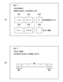
図3(A)は、操作部21に表示される除去色の選択画面である。ユーザは、コピーの原稿から指定色を除去して記録媒体に印刷させる場合、図3(A)の画面において、除去色を指定する。図3(A)では、有彩色である赤色、青色、緑色と、無彩色である黒色とを選択ボタンで選択できる。また、図3(B)は、指定する除去色の色合いを選択する画面である。図3(B)は赤色を指定した場合での、色合いの選択画面である。図3(B)において、ユーザは除去色の色合いを細かく指定することができる。ユーザは、コピー機能の設定が完了すると、操作部21のスタートボタンを操作する。これにより、色指定手段としての制御部11は、スタートボタンが操作された時点での設定内容に基づいて、コピー処理のためのスキャンジョブ、画像処理ジョブ、印刷ジョブを生成する。スキャンジョブは、スキャナ部23が原稿を読み取るジョブである。スキャナ部23は、スキャンジョブを実行し、例えばカラー画像データを生成する。画像処理ジョブは、制御部11がスキャンによる画像を加工するジョブである。スキャナ部23がカラー画像データを生成し終えると、制御部11は、画像処理ジョブを実行する。制御部11は、印刷用のカラー画像データを生成する。印刷ジョブは、プリンタ部22がカラー画像データを記録媒体に印刷するジョブである。制御部11が画像処理ジョブにより印刷用のカラー画像データを生成し終えると、プリンタ部22は、印刷ジョブを実行する。プリンタ部22は、印刷用のカラー画像データに基づいて、記録媒体にカラー画像を印刷する。これにより、画像形成装置10は、原稿のカラー画像を読み取り、読み取ったカラー画像に対応する画像を記録媒体に形成することができる。この際、図3の選択画面において除去色が指定されている場合、制御部11は、原稿をスキャンしたカラー画像から、指定された除去色の色成分を除去した印刷用のカラー画像データを生成する。
FIG. 3A is a removal color selection screen displayed on the
図4は、指定色除去処理を説明する図である。図4(A)の原稿には、図において左下がり斜線パターンで示す領域Aに印刷された黒色の文字と、格子パターンで示す領域Bに印刷された赤色の文字とが、印刷されている。図において、各文字は、「*」で現わされている。このような原稿について、除去色として赤を指定すると、図4(B)のカラー画像が記録媒体に印刷される。図4(B)のカラー画像では、左下がり斜線パターンで示す領域Aにのみ文字が黒色で印刷される。格子パターンで示す領域Bには、赤色の文字が印刷されていない。 FIG. 4 is a diagram illustrating a designated color removal process. In the manuscript of FIG. 4A, black characters printed in the area A shown by the downward-sloping diagonal line pattern and red characters printed in the area B shown by the grid pattern are printed. In the figure, each character is represented by "*". When red is specified as the removal color for such a document, the color image of FIG. 4B is printed on the recording medium. In the color image of FIG. 4B, the characters are printed in black only in the area A indicated by the downward-sloping diagonal line pattern. Red characters are not printed in the area B indicated by the grid pattern.
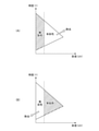
次に、カラー画像データの指定色除去処理の基本的な処理について説明する。図5(A)は、赤、青または緑の有彩色を除去する処理の説明図である。図5(A)は、横軸を彩度(UV)とし、縦軸を明度(Y)とした色平面の説明図である。原点は、黒色である。三角形の色平面についての縦軸上の頂点は、白色である。三角形の色平面についての残りの頂点は、たとえば赤の純色である。したがって、この色平面において、縦軸に沿って上へ行くほどに黒色の濃度が低くなる。三角形の色平面の下辺に沿って純色の頂点へ行くほど、赤色の成分が高くなる。このため、所定の彩度閾値より図示左側の領域は略無彩色の領域となる。彩度閾値より図示右側の領域は略有彩色の領域となる。赤、青または緑の有彩色を除去する場合、制御部11は、カラー画像データの各画素の色が、彩度閾値より図示右側の有彩色領域に含まれるか否かを判断する。そして、有彩色領域に含まれる場合、制御部11は、その画素の色を白色へ変換して除去する。また、彩度閾値より図示左側の無彩色領域に含まれる場合、制御部11は、その画素の色成分を残す。この処理を、カラー画像を構成するすべての画素について実行することにより、制御部11は、スキャンによるカラー画像から、指定された有彩色を除去できる。
Next, the basic processing of the designated color removal processing of the color image data will be described. FIG. 5A is an explanatory diagram of a process for removing chromatic colors of red, blue, or green. FIG. 5A is an explanatory diagram of a color plane in which the horizontal axis is saturation (UV) and the vertical axis is lightness (Y). The origin is black. The vertices on the vertical axis for the color plane of the triangle are white. The remaining vertices for the color plane of the triangle are, for example, the pure color of red. Therefore, in this color plane, the density of black becomes lower as it goes up along the vertical axis. The red component becomes higher toward the apex of the pure color along the lower edge of the color plane of the triangle. Therefore, the region on the left side of the drawing from the predetermined saturation threshold is a region having a substantially achromatic color. The area on the right side of the figure from the saturation threshold is a substantially chromatic area. When removing the chromatic colors of red, blue, or green, the
しかしながら、このように指定された除去色を一律にカラー画像から除いた場合、除去処理した後のカラー画像には、本来の画像にはない画像が表れてしまうことがある。図6は、指定色の除去処理により除去処理した後のカラー画像に本来の画像にはないスジが発生する場合の説明図である。図6には、4行3列の計12パターンのカラーコピーの説明図である。第1行は、無彩色の濃い黒系色の背景に、有彩色の濃いスジが形成されたスキャンカラー画像をコピーする場合である。第2行は、濃い有彩色の背景に、無彩色の濃い黒系のスジが形成されたスキャンカラー画像をコピーする場合である。第3行は、無彩色の薄い白系色の背景に、有彩色の薄いスジが形成されたスキャンカラー画像をコピーする場合である。第4行は、薄い有彩色の背景に、無彩色の薄い白系色のスジが形成されたスキャンカラー画像をコピーする場合である。そして、除去色を指定しない通常のコピーでは、制御部11は、いずれの場合でもスジの濃さと背景の濃さとが近いため、第1列に示すようにスジが目立たないようにコピー画像を形成できる。これに対し、有彩色を除去色に指定した場合、制御部11は、第2列に示すように指定色の背景または黒スジのみを除去してしまうため、第1行および第2行のように背景およびスジが共に濃い色である場合には、無彩色の背景または黒スジが残存する。この場合、スジが目立つように明確に形成されてしまう。また、無彩色を除去色に指定した場合、制御部11は、第3列に示すように無彩色の濃い黒色の背景や黒スジのみを除去してしまうため、第1行および第2行のように背景およびスジが共に濃い色である場合には、有彩色の背景または黒スジが残存する。この場合、スジが目立つように明確に形成されてしまう。このように、本来の画像にはないスジの画像が形成されてしまうことになる。なお、第3行や第4行のように原稿が薄い場合には、同様に背景またはスジのみが残されたとしても、スジがそれほど目立たない。
However, when the removed colors designated in this way are uniformly removed from the color image, an image that is not in the original image may appear in the color image after the removal process. FIG. 6 is an explanatory diagram in the case where a streak not found in the original image is generated in the color image after the removal process of the designated color. FIG. 6 is an explanatory diagram of a total of 12 patterns of color copying in 4 rows and 3 columns. The first line is a case of copying a scan color image in which dark streaks of chromatic color are formed on a background of dark black color of achromatic color. The second line is a case of copying a scan color image in which achromatic dark black streaks are formed on a dark chromatic background. The third line is a case of copying a scan color image in which a chromatic light streak is formed on an achromatic light white background. The fourth line is a case of copying a scan color image in which achromatic pale white streaks are formed on a pale chromatic background. Then, in a normal copy in which the removal color is not specified, the
次に、カラー画像をコピーした原稿にスジが形成されてしまう一因についてさらに詳しく説明する。図7は、スキャナ部23の概略構成を示す説明図である。スキャナ部23は、図1の画像形成装置10の上部に配置される。図7には、スキャナ部23についての、読取ガラス31、ADFの搬送ローラ32、複数の反射ミラー33、結像レンズ34、カラーラインセンサ35、が図示されている。ADFの搬送ローラ32は、読取ガラス31の上側において回転可能に配置される。これにより読取ガラス31の上側に、原稿の読取位置36が構成される。搬送ローラ32は、スキャンジョブを実行するにあたり、ADFの原稿トレイから搬送された原稿を送り、読取位置36を通過させる。カラーラインセンサ35は、読取ガラス31の下側において位置決めして配置される。複数の反射ミラー33、結像レンズ34は、原稿の読取位置36とカラーラインセンサ35との間に読取り光学系を構成する。カラーラインセンサ35は、搬送されながら読取位置36を通過する原稿の読取光を受光し、原稿のカラー画像をスキャンしたカラー画像データを生成する。スキャナ部23は、スキャンによるカラー画像データを、画像形成装置10の制御部11へ出力する。そして、図8に示すように、読取位置36にゴミが付着している場合、原稿を搬送しながら読み取ったカラー画像には、ごみによるスジ状の欠損が生じ得る。
Next, one cause of streaks being formed in a document on which a color image is copied will be described in more detail. FIG. 7 is an explanatory diagram showing a schematic configuration of the
図8は、スキャンジョブに続けて画像処理ジョブを実行する際に制御部11に実現される処理手段を示す説明図である。画像処理ジョブを実行する際に制御部11には、ゴミスジ検知部41、ゴミスジ位置記憶部42、ゴミスジ補正部43、スキャナ画像処理部44、輝度濃度変換処理部45、ガンマ処理部46、ハーフトーン処理部47、ドット付加部48、が実現される。これら各機能部は、画像形成装置10が有しているCPU12が制御プログラムを実行することにより実現される。また、図8には、画像形成装置10のスキャナ部23、プリンタ部22が併せて図示されている。欠損判断手段としてのゴミスジ検知部41は、スキャナ部23のカラーラインセンサ35で取得されたR,G,B各色の色成分値を取得し、スキャンによるカラー画像にゴミスジによる欠損が発生しているかを検知する。ここで、ゴミスジによる欠損位置は、読取位置36における原稿の搬送方向に直交する方向における位置で現わされる。ゴミスジ位置記憶部42は、ゴミスジ検知部41により検知されたゴミスジ位置を記憶する。ゴミスジ補正部43は、ゴミスジ位置記憶部42に記憶されるゴミスジ位置に基づいて、ゴミスジ位置の画素を周辺画素の色成分値を用いて補間する処理を実行する。
FIG. 8 is an explanatory diagram showing a processing means realized by the
図9は、図8のスキャナ画像処理部44の詳細な処理手段の説明図である。図9のスキャナ画像処理部44は、MTF補正処理部51、ガンマ処理部52、色変換処理部53、色判定処理部54、彩度抑圧処理部55、フィルタ処理部56、像域処理部57、を有する。MTF補正処理部51は、読取速度によって変化する読み取りのMTFを補正する。像域処理部57は、MTF処理後の画像を用いて文字や、写真などの像域を判定する。ガンマ処理部52は、スキャナ部23の特性に応じた1次元のガンマ補正処理を実行する。色変換処理部53は、スキャナ部23の色空間から、スキャナ部23に依存しない色空間へ変換する。色判定処理部54は、像域情報を用いて、有彩色か無彩色かを判定する。彩度抑圧処理部55は、像域情報にしたがって、無彩色と判定された画像に対してRGBの量を補正する。たとえば色判定処理部54において無彩色と判定された場合、彩度抑圧処理部55は、RGBを等量にするなどの処理を行う。フィルタ処理部56では、像域情報に従ってスムージングやエッジ強調などを行う。
FIG. 9 is an explanatory diagram of a detailed processing means of the scanner
図8のハーフトーン処理部47は、カラー画像データの階調値(例えば、256階調)を、プリンタ部22で出力可能な階調であるN値(例えば2値)の画像データ(ハーフトーン画像データ)に変換する処理を行う。ドット付加部48は、あらかじめ定められたドットを付加する。これら一連の処理により、制御部11は、スキャンによるカラー画像を、プリンタ部22が印刷可能にカラー画像へ変換する。制御部11は、生成した印刷用のカラー画像データを、プリンタ部22へ出力する。プリンタ部22は、印刷ジョブを実行し、印刷用のカラー画像を記録媒体に印刷する。
The
図10は、色空間の変換処理で用いるノーマルの3次元LUT(ルックアップテーブル)の説明図である。図10の3次元LUTは、入力側であるスキャン部にRGBの3次元の色空間を、プリンタ部22で利用可能にするための出力側の他のRGBの3次元の色空間へ変換するものである。色空間変換処理は、たとえばデバイスに依存した特性を持つR、G、B信号を、デバイス非依存な色空間R’、G’、B’へ変換するものである。また、図10の3次元LUTは、入力側の色空間の値を15の単位で間引く例である。この場合、3次元LUTは、4096個の変換レコードを有する。各変換レコードは、入力側のRGBの色成分値の上限値と、それに対応する出力側のRGBの色成分値とを有する。各色成分の階調数は、1/16に間引かれる。たとえば入力側が(R,G,B)=(0,0,15)である場合、色変換処理部53は、3次元LUTを用いてR、G、B信号を(0,0,19)へ変換する。
FIG. 10 is an explanatory diagram of a normal three-dimensional LUT (look-up table) used in the color space conversion process. The three-dimensional LUT of FIG. 10 converts the RGB three-dimensional color space in the scan unit on the input side into another RGB three-dimensional color space on the output side for use in the
図11は、図9のスキャナ部23の読取位置36にごみが付着している場合での、カラー画像の変換処理の説明図である。図9のスキャナ部23で原稿を読み取る際に読取位置36にごみが付着している場合、図8のゴミスジ検知部41は、スキャンによるカラー画像においてこれを検出する。ゴミスジ位置記憶部42は、ゴミスジ検知部41により検知されたゴミスジ位置を記憶する。ゴミスジ補正部43は、ゴミスジ位置記憶部42に記憶されるゴミスジ位置に基づいて、ゴミスジ位置の画素を周辺画素の色成分値を用いて補間する処理を実行する。図11(A)の原稿のカラー画像は、白と黒とが交互になる複数の線の画像部分を有する。図11(A)の原稿をスキャンしたカラー画像にスジによる欠損が生じている場合、スキャナ画像処理部44は、図11(B)に示すように欠損が生じているスジ位置の画素を周囲の画素の色で補間したカラー画像を形成する。図11(B)の画像には、図11(A)の本来の画像にはない欠損による画像成分が含まれてしまう。また、欠損を補間したスジ位置の画素の色は、欠損前の黒色ではなく、たとえば黒色に近い有彩色となる。そして、この図11(B)の画像を原稿としてスキャンし、スジ位置の有彩色を含む色を除去する処理をした場合、図11(C)に示すように欠損したスジ位置の画素の色は白色に置き換えられて除去されてしまう。その結果、図11(C)の再スキャン後のカラー画像では、図11(A)のオリジナルの原稿または図11(B)のコピー原稿でははっきりと表れていないスジがはっきりと形成されてしまう。これとは逆に、黒色を除去する処理をした場合、欠損したスジ位置の画素の色が、残存してしまう。このように画像形成装置10では、指定色の除去処理を改善することが求められている。
FIG. 11 is an explanatory diagram of a color image conversion process when dust is attached to the
図12は、本実施形態での指定色の除去処理の基本的な考え方を説明する図である。図12(A)は、有彩色を除去する場合の説明図である。図12(B)は、無彩色(黒)を除去する場合の説明図である。図12において、横軸は彩度(UV)であり、縦軸は明度(Y)である。三角形で示される色領域の原点における頂点は黒色であり、縦軸における他の頂点は白色であり、残りの頂点は純色である。この三角形の色領域に対して、第一彩度閾値T1と、明度閾値T2と、が設定される。第一彩度閾値T1は、三角形の色領域を、有彩色と無彩色とに分ける閾値である。第一彩度閾値T1より左側の彩度値が小さい領域は、黒、白、灰といった無彩色の領域となる。第一彩度閾値T1より右側の彩度値が大きい領域は、有彩色の領域となる。明度閾値T2は、有彩色の領域を、濃い有彩色の領域と、薄い有彩色の領域とに分ける閾値である。そして、有彩色を除去する場合、図12(A)に示すように、明度閾値以上であって且つ第一彩度閾値以上である色領域の色は、無色(白)へ変換して除去される。これにより、たとえば濃い無彩色の背景に、濃い有彩色のスジが形成されている場合、それらの双方を除去しないようにできる。また、無彩色を除去する場合、図12(B)に示すように、第一彩度閾値以下の無彩色の黒色とともに、明度閾値以下の有彩色は、無色(白)へ変換して除去される。これにより、たとえば濃い無彩色の背景に、濃い有彩色のスジが形成されている場合、それらの双方を除去することができる。 FIG. 12 is a diagram illustrating a basic concept of a designated color removal process in the present embodiment. FIG. 12A is an explanatory diagram when the chromatic color is removed. FIG. 12B is an explanatory diagram when the achromatic color (black) is removed. In FIG. 12, the horizontal axis is saturation (UV) and the vertical axis is lightness (Y). The vertices at the origin of the color region represented by the triangles are black, the other vertices on the vertical axis are white, and the remaining vertices are pure colors. A first saturation threshold value T1 and a lightness threshold value T2 are set for the color region of the triangle. The first saturation threshold value T1 is a threshold value for dividing the color region of the triangle into a chromatic color and an achromatic color. The region having a small saturation value on the left side of the first saturation threshold T1 is an achromatic region such as black, white, or gray. The region on the right side of the first saturation threshold T1 having a large saturation value is a chromatic region. The lightness threshold T2 is a threshold that divides the chromatic region into a dark chromatic region and a light chromatic region. Then, when removing the chromatic color, as shown in FIG. 12A, the color in the color region which is equal to or higher than the lightness threshold value and equal to or higher than the first saturation threshold value is converted to colorless (white) and removed. To. As a result, for example, when dark chromatic streaks are formed on a dark achromatic background, both of them can be prevented from being removed. When removing the achromatic color, as shown in FIG. 12B, the achromatic color black below the first saturation threshold and the chromatic color below the lightness threshold are converted to colorless (white) and removed. To. Thereby, for example, when dark chromatic streaks are formed on a dark achromatic background, both of them can be removed.
図13は、色差空間平面上における色相環を示す。図13には、赤の色相角度、青の色相角度、および緑の色相角度、が合わせて図示されている。そして、除去色として赤が指定される場合、赤の色相角度を中心にとしたその両側の色相幅閾値に相当する角度幅の範囲の色は、除去処理の対象となる。本実施形態では、図12および図13の考え方に基づいて出力側の値が変更された、除去用の3次元ルックアップテーブルを用いる。除去用の3次元ルックアップテーブルは、図10の各画素の色成分値を変換するだけの3次元ルックアップテーブルとともに、HDD15などの記憶部に記憶される。除去用の3次元ルックアップテーブルでは、図10のノーマルの3次元ルックアップテーブル61と比較した場合、図12および図13により除去するとされる色に対応する出力側の値が白色を示す値に変更されている。図10の出力側の値の一部は、白色を示す値に変更されている。黒色を除去するための除去用の3次元ルックアップテーブルは、有彩色と異なり色相環が無いため、図12の考え方のみに基づいて出力側の値を変更すればよい。具体的には、無彩色の黒色を除去するための除去用の3次元ルックアップテーブルは、第一彩度閾値T1以下の無彩色を色変換する変換レコードの出力側の値は、白色を示す値とされる。同様に、明度閾値T2以下の明度の黒色に近い一部の有彩色を色変換する変換レコードの出力側の値は、白色を示す値とされる。有彩色を除去するための除去用の3次元ルックアップテーブルは、明度閾値T2以上であって且つ第一彩度閾値T1以上である有彩色を色変換する変換レコードの出力側の値は、白色を示す値とされる。
FIG. 13 shows the color wheel on the color difference space plane. FIG. 13 also illustrates the red hue angle, the blue hue angle, and the green hue angle. When red is designated as the removal color, the color in the range of the angle width corresponding to the hue width thresholds on both sides of the hue angle of red is the target of the removal processing. In this embodiment, a three-dimensional look-up table for removal is used, in which the values on the output side are changed based on the ideas of FIGS. 12 and 13. The three-dimensional look-up table for removal is stored in a storage unit such as the
そして、図9の色変換処理部53は、RGBの色空間の変換処理の際に、指定された色を除去する処理を実行する。この際、色変換処理部53は、図10のノーマルの3次元ルックアップテーブル61と、有彩色除去用の3次元ルックアップテーブル62と、無彩色除去用の3次元ルックアップテーブル63とから1つを選択して用いる。
Then, the color
この場合、図9に示すように、色変換処理部53は、ゴミスジ位置記憶部42、ノーマルの3次元ルックアップテーブル61、有彩色除去用の3次元ルックアップテーブル62、および無彩色除去用の3次元ルックアップテーブル63、を利用する。ゴミスジ位置記憶部42は、画像にスジがある場合にはそのスジ位置を記憶する。3種類の3次元ルックアップテーブルは、HDD15などの記憶部に記憶される。なお、有彩色除去用の3次元ルックアップテーブル62は、ユーザによる図3の画面での操作に基づいて指定された除去色を除去するものである。有彩色除去用の3次元ルックアップテーブル62および無彩色除去用の3次元ルックアップテーブル63は、ユーザによる除去色の設定に基づいて画像形成装置10においてノーマルの3次元ルックアップテーブル61から適宜調整して生成されてよい。
In this case, as shown in FIG. 9, the color
図14は、図9の色変換処理部53による、色変換処理を示すフローチャートである。図9の色変換処理部53は、スキャナ部23が原稿をスキャンしてカラー画像データを生成した場合に図14の処理を実行する。図14において、色変換処理部53は、まず、スキャンによるカラー画像データの画像にスジがあるか否かを判断する(S01)。図9のゴミスジ位置記憶部42には、図8のゴミスジ検出部の処理により、ごみによるスジ状の欠陥位置(スジ位置)の情報が記憶されている。色変換処理部53は、ゴミスジ位置記憶部42にスジ位置が記憶されている場合、画像にスジがあると判断し、それ以外の場合には画像にスジがないと判断すればよい。画像にスジがない場合、色変換処理部53は、ノーマルの3次元ルックアップテーブル61を取得する(S02)。画像にスジがある場合、色変換処理部53は、さらに除去色として有彩色が指定されているか否かを判断する(S03)。有彩色が指定されている場合、色変換処理部53は、有彩色除去用の3次元ルックアップテーブル62を取得する(S04)。除去色として有彩色が指定されていない場合、色変換処理部53は、さらに除去色として無彩色が指定されているか否かを判断する(S05)。無彩色が指定されている場合、色変換処理部53は、無彩色除去用の3次元ルックアップテーブル63を取得する(S06)。除去色として有彩色も無彩色も指定されていない場合、色変換処理部53は、ノーマルの3次元ルックアップテーブル61を取得する(S02)。
FIG. 14 is a flowchart showing a color conversion process by the color
いずれかの3次元ルックアップテーブルを取得した後、色変換処理部53は、スキャンによるカラー画像データから、1つの画素の色成分値を取得する(S07)。次に、色変換処理部53は、取得した3次元ルックアップテーブルを用いて、処理に係る画素の色成分値を変換する(S08)。その後、色変換処理部53は、スキャンによるカラー画像データのすべての画素について色変換処理を実施したか否かを判断する(S09)。すべての画素について色変換処理を実施し終えていない場合、色変換処理部53は、処理をステップS07へ戻し、次の画素を取得して色変換処理を実行する。すべての画素についての色変換処理が終了している場合、色変換処理部53は、図14の処理を終了する。そして、有彩色除去用の3次元ルックアップテーブル62を用いて色変換をした場合、図12(A)において明度閾値T2以上であって且つ第一彩度閾値T1以上である有彩色は、白色に変換されることにより除去される。無彩色除去用の3次元ルックアップテーブル63を用いて色変換をした場合、図12(B)において第一彩度閾値T1以下である無彩色とともに、第一彩度閾値T1以下である黒色に近い有彩色は、白色に変換されることにより除去される。
After acquiring any of the three-dimensional look-up tables, the color
図15は、図14の色変換処理により指定色が除去されたカラー画像の説明図である。図15には、図6と同様に4行3列の計12パターンのカラーコピーの説明図である。各パターンのカラーコピーは、図6のものに対応する。そして、第1行のように無彩色の濃い黒系色の背景に有彩色の濃いスジが形成されたスキャンカラー画像について、有彩色を除去してコピーする場合、第2列に示すように黒色の背景と濃い有彩色のスジとは、ともに除去されない。また、第2行のように濃い有彩色の背景に無彩色の黒いスジが形成されたスキャンカラー画像について、有彩色を除去してコピーする場合、第2列に示すように濃い有彩色の背景と無彩色の黒いスジとは、ともに除去されない。また、第1行のように無彩色の濃い黒系色の背景に有彩色の濃いスジが形成されたスキャンカラー画像について、無彩色を除去してコピーする場合、第3列に示すように黒色の背景と濃い有彩色のスジとは、ともに除去される。また、第2行のように濃い有彩色の背景に無彩色の黒いスジが形成されたスキャンカラー画像について、有彩色を除去してコピーする場合、第3列に示すように濃い有彩色の背景と無彩色の黒いスジとは、ともに除去される。このように、コピーした画像では、スジが目立ちにくくなる。 FIG. 15 is an explanatory diagram of a color image from which a designated color has been removed by the color conversion process of FIG. FIG. 15 is an explanatory diagram of a total of 12 patterns of color copying in 4 rows and 3 columns, as in FIG. 6. The color copy of each pattern corresponds to that of FIG. Then, when copying a scan color image in which dark streaks of chromatic color are formed on a background of dark black color of achromatic color as in the first row, when the chromatic color is removed and copied, black is used as shown in the second column. Both the background and the dark chromatic streaks are not removed. Further, when copying a scan color image in which an achromatic black streak is formed on a dark chromatic background as in the second row after removing the chromatic color, the dark chromatic background is shown in the second column. And the achromatic black streaks are not removed either. In addition, when copying a scan color image in which dark streaks of chromatic color are formed on a background of dark black color of achromatic color as in the first row, when the achromatic color is removed and copied, black is used as shown in the third column. Both the background and the dark chromatic streaks are removed. Further, when copying a scan color image in which an achromatic black streak is formed on a dark chromatic background as in the second row after removing the chromatic color, the dark chromatic background is shown in the third column. And the achromatic black streaks are both removed. In this way, the streaks are less noticeable in the copied image.
以上のように、本実施形態では、取得したカラー画像データから除去指定された色を除去する処理では、図12に示すように明度閾値T2および第一彩度閾値T1に基づいて除去すると判断される色領域の色を無色(白)へ変換して除去する。よって、本実施形態では、たとえば有彩色の濃い除去色の背景に無彩色の濃い黒スジが含まれるカラー画像を取得した場合には、それらの双方を除去しないようになる。これに対し、図5のように仮にたとえば有彩色と無彩色との判断のための第一彩度閾値T1のみに基づいて指定色除去を判断した場合、指定色を除去した後の画像では、有彩色の濃い除去色の背景が除去される。無彩色の濃い黒スジは、無彩色の白色の背景に残して形成されてしまう。元画像よりも黒スジが目立つようになる。本実施形態では、このような画像を形成し難くできる。 As described above, in the present embodiment, it is determined that in the process of removing the specified color to be removed from the acquired color image data, the color is removed based on the lightness threshold T2 and the first saturation threshold T1 as shown in FIG. The color of the color area is converted to colorless (white) and removed. Therefore, in the present embodiment, for example, when a color image in which an achromatic dark black streak is included in the background of a chromatic dark removal color is acquired, both of them are not removed. On the other hand, as shown in FIG. 5, if the designated color removal is determined based only on the first saturation threshold T1 for determining chromatic color and achromatic color, for example, in the image after the designated color is removed, the image is displayed. Saturated dark removal The background of the color is removed. Achromatic dark black streaks are formed by leaving them on an achromatic white background. Black streaks become more noticeable than the original image. In this embodiment, it is possible to make it difficult to form such an image.
本実施形態では、除去色として指定された有彩色のうちで、明度閾値T2以上であって且つ第一彩度閾値T1以上である色領域の色を無色(白)へ変換して除去する。よって、たとえば有彩色の濃い除去色の背景に無彩色の濃い黒スジが含まれるカラー画像を取得した場合には、それらの双方を除去しない。また、無彩色の濃い黒色の背景に有彩色の濃いスジが含まれるカラー画像を取得した場合には、それらの双方を除去しない。指定色除去処理後の画像において、濃いスジのみが目立つように印刷されてしまうことを防止できる。本実施形態では、除去色として指定された第一彩度閾値T1以下の無彩色の黒色とともに、明度閾値T2以下の有彩色を、無色(白)へ変換して除去する。よって、たとえば有彩色の濃い除去色の背景に無彩色の濃い黒スジが含まれるカラー画像を取得した場合には、それらの双方を除去する。また、無彩色の濃い黒色の背景に有彩色の濃いスジが含まれるカラー画像を取得した場合には、それらの双方を除去する。指定色除去処理後の画像において、濃いスジのみが目立つように印刷されてしまうことを防止できる。本実施形態では、取得するカラー画像データの画像についての欠損を判断し、欠損がある場合には、明度閾値T2および第一彩度閾値T1に基づく判断により除去処理を実行する。よって、画像がスジなどの欠損を有する場合でも、スジなどの欠損が目立たなくなるように好適な除去処理を実施できる。本実施形態では、画像形成装置10により記録媒体に印刷された画像をスキャンした画像についてのカラー画像データを取得する。この場合、ごみの読取位置に生じるスジを目立たなくするように、スジ位置の周辺画素の色成分を用いてスジ位置の画素の色成分を補間処理している。スジが目立たなくなるように色成分が補間されたスジ位置およびその周辺部分の色成分は、本来の色成分とは異なるものとなっている。本実施形態では、このような補間処理後の画像をスキャンしたカラー画像データを取得した場合であっても、補間処理されたスジが目立ち難くなるように指定色を除去することができる。
In the present embodiment, among the chromatic colors designated as the removal colors, the color in the color region having the lightness threshold value T2 or more and the first saturation threshold value T1 or more is converted to colorless (white) and removed. Therefore, for example, when a color image in which an achromatic dark black streak is included in the background of a chromatic dark removal color is acquired, both of them are not removed. Further, when a color image including dark streaks of chromatic color is acquired on a dark black background of achromatic color, both of them are not removed. In the image after the designated color removal process, it is possible to prevent only dark streaks from being printed so as to be conspicuous. In the present embodiment, the achromatic black color having the first saturation threshold T1 or less designated as the removal color and the chromatic color having the lightness threshold T2 or less are converted into colorless (white) and removed. Therefore, for example, when a color image in which an achromatic dark black streak is included in the background of a chromatic dark removal color is acquired, both of them are removed. In addition, when a color image containing dark streaks of chromatic color is acquired on a dark black background of achromatic color, both of them are removed. In the image after the designated color removal process, it is possible to prevent only dark streaks from being printed so as to be conspicuous. In the present embodiment, a defect in the image of the acquired color image data is determined, and if there is a defect, the removal process is executed by determination based on the brightness threshold value T2 and the first saturation threshold value T1. Therefore, even if the image has defects such as streaks, a suitable removal process can be performed so that the defects such as streaks become inconspicuous. In the present embodiment, color image data of an image obtained by scanning an image printed on a recording medium by the
[第二実施形態]
次に、本発明の第二実施形態に係る画像形成装置10について説明する。以下の説明では、主に第一実施形態の画像処理装置との相違点について説明する。
[Second Embodiment]
Next, the
図16は、第二実施形態での指定色の除去処理の基本的な考え方を説明する図である。図16(A)は、有彩色を除去する場合の説明図である。図16(B)は、無彩色(黒)を除去する場合の説明図である。図16においても図12と同様に、横軸は彩度(UV)であり、縦軸は明度(Y)である。三角形で示される色領域の原点における頂点は黒色であり、縦軸における他の頂点は白色であり、残りの頂点は純色である。この三角形の色領域に対して、第一彩度閾値T1と、第二彩度閾値T3と、明度閾値T2と、が設定される。第二彩度閾値T3は、有彩色と無彩色との境界である第一彩度閾値T1より高い彩度の閾値である。そして、無彩色除去用の3次元ルックアップテーブル63と、有彩色除去用の3次元ルックアップテーブル62とは、図16において除去する色領域に属する出力側のRGBの色成分値が、無色(白)に変更される。 FIG. 16 is a diagram illustrating a basic concept of a designated color removal process in the second embodiment. FIG. 16A is an explanatory diagram when the chromatic color is removed. FIG. 16B is an explanatory diagram when the achromatic color (black) is removed. In FIG. 16, as in FIG. 12, the horizontal axis is saturation (UV) and the vertical axis is lightness (Y). The vertices at the origin of the color region represented by the triangles are black, the other vertices on the vertical axis are white, and the remaining vertices are pure colors. A first saturation threshold value T1, a second saturation threshold value T3, and a lightness threshold value T2 are set for the color region of the triangle. The second saturation threshold T3 is a saturation threshold higher than the first saturation threshold T1 which is the boundary between the chromatic color and the achromatic color. In the three-dimensional look-up table 63 for removing achromatic colors and the three-dimensional look-up table 62 for removing chromatic colors, the RGB color component values on the output side belonging to the color region to be removed in FIG. 16 are colorless (). It is changed to white).
そして、色変換処理部53は、明度閾値T2、第一彩度閾値T1および第二彩度閾値T3に基づく判断により除去すると判断される色領域の色を、除去用の3次元ルックアップテーブルを用いて、無色(白)へ変換して除去する。たとえば有彩色を除去する場合、図12(A)に示すように、明度閾値T2以上であって且つ第一彩度閾値T1以上である色領域の色と、明度閾値T2以下であって且つ第二彩度閾値T3以上である色領域の色とを、無色(白)へ変換して除去する。色変換処理部53は、有彩色除去用の3次元ルックアップテーブル62を用いて、この処理を実施する。これにより、たとえば濃い無彩色の背景に、濃い有彩色のスジが形成されている場合、それらの双方を除去しないようにできる。スジが目立たない効果を損なうことなく、第1実施形態より広い範囲において指定された除去色を除去できる。また、無彩色を除去する場合、図12(B)に示すように、第一彩度閾値T1以下の無彩色の黒色と、明度閾値T2以下であって且つ第二彩度閾値T3以下である色領域の色とを、無色(白)へ変換して除去する。色変換処理部53は、無彩色除去用の3次元ルックアップテーブル63を用いて、この処理を実施する。これにより、たとえば濃い無彩色の背景に、濃い有彩色のスジが形成されている場合、それらの双方を除去することができる。スジが目立たない効果を損なうことなく、第1実施形態より広い範囲において、除去色に指定されていない有彩色を残すことができる。
Then, the color
以上のように、本実施形態では、有彩色と無彩色との境界である第一彩度閾値T1より高い彩度の第二彩度閾値T3以下であるか否かを判断し、それに応じて除去色を無色(白)へ変換して除去する。よって、本実施形態は、たとえば無彩色の濃い黒色の背景に、黒とは異なる中間的な濃さの有彩色のスジ成分を本来的に含むカラー画像を取得した場合には、指定色の指定どおりにスジ成分を除去することができる。画像本来に含まれている明度閾値T2以下の明るさの有彩色のスジ成分を除去することができる。 As described above, in the present embodiment, it is determined whether or not the saturation is equal to or less than the second saturation threshold T3, which is higher than the first saturation threshold T1 which is the boundary between the chromatic color and the achromatic color, and accordingly. The removal color is converted to colorless (white) and removed. Therefore, in the present embodiment, for example, when a color image originally containing a chromatic streak component having an intermediate darkness different from black is acquired on a dark black background of an achromatic color, a designated color is designated. The streak component can be removed as per. It is possible to remove a chromatic streak component having a brightness of T2 or less, which is originally included in the image.
本発明は、上述の実施の形態の1以上の機能を実現するプログラムを、ネットワークや記憶媒体を介してシステムや装置に供給し、そのシステム又は装置のコンピュータの1つ以上のプロセッサがプログラムを読み出して実行する処理でも実現可能である。また、本発明は、1以上の機能を実現する回路(例えば、ASIC)によっても実現可能である。 The present invention supplies a program that realizes one or more functions of the above-described embodiment to a system or device via a network or storage medium, and one or more processors of the computer of the system or device reads the program. It can also be realized by the process to be executed. The present invention can also be realized by a circuit (for example, ASIC) that realizes one or more functions.
上記実施形態では、ノーマルの3次元ルックアップテーブル61とともに、有彩色除去用の3次元ルックアップテーブル62および無彩色除去用の3次元ルックアップテーブル63を用いて、色変換処理において、指定された除去色を合わせて除去している。この他にもたとえば、指定色の除去処理は、色変換処理とは別の処理として実施されてよい。この場合、各画素の処理において、画素の色成分値と明度閾値T2、第一彩度閾値T1および第二彩度閾値T3とを比較し、除去の要否を判断すればよい。この場合でも、RGBの色空間において図12や図16の判断をすることにより、プリンタ部22のカラー印刷において特定の色成分に対応するトナーを用いないことにより指定色を除去する場合よりも、より適切に指定された除去色を除去することができる。
In the above embodiment, the three-dimensional look-up table 62 for removing chromatic colors and the three-dimensional look-up table 63 for removing chromatic colors are used together with the normal three-dimensional look-up table 61, and are designated in the color conversion process. The removal color is matched and removed. In addition to this, for example, the designated color removal process may be performed as a process different from the color conversion process. In this case, in the processing of each pixel, the color component value of the pixel may be compared with the lightness threshold value T2, the first saturation threshold value T1 and the second saturation threshold value T3, and the necessity of removal may be determined. Even in this case, by making a judgment in FIGS. 12 and 16 in the RGB color space, the designated color is removed by not using the toner corresponding to the specific color component in the color printing of the
10 画像形成装置
21 操作部
22 プリンタ部
23 スキャナ部
36 読取位置
41 ゴミスジ検知部
42 ゴミスジ位置記憶部
44 スキャナ画像処理部
53 色変換処理部
61 ノーマルの3次元ルックアップテーブル
62 有彩色除去用の3次元ルックアップテーブル
63 無彩色除去用の3次元次元ルックアップテーブル
T1 第一彩度閾値
T2 明度閾値
T3 第二彩度閾値
10
Claims (13)
前記取得手段によって取得される前記カラー画像データから除去する色を指定する色指定手段と、
前記取得手段によって取得された前記カラー画像データから、前記色指定手段によって指定された色と明度の閾値および彩度の閾値に基づいて除去するよう判定された色を除去する除去手段と、を有し、
前記色指定手段が有彩色を指定した場合に、前記除去手段は、前記色指定手段によって指定された有彩色における前記明度の閾値より小さい明度の色、及び前記彩度の閾値より小さい彩度の色を除去せずに、前記色指定手段によって指定された有彩色における前記明度の閾値以上の明度であって、且つ、前記彩度の閾値以上の彩度の色を除去することを特徴とする画像形成装置。 An acquisition method for acquiring color image data,
A color specifying means for designating a color to be removed from the color image data acquired by the acquiring means, and
The color image data acquired by the acquisition means is provided with a removing means for removing a color determined to be removed based on the color specified by the color designating means, the lightness threshold value, and the saturation threshold value. death,
When the color designating means designates a chromatic color, the removing means has a lightness color smaller than the lightness threshold in the chromatic color designated by the color designating means , and a saturation smaller than the saturation threshold. It is characterized in that it removes a color having a brightness equal to or higher than the threshold value of the lightness and having a saturation equal to or higher than the threshold value of the saturation in the chromatic color designated by the color designating means without removing the color. Image forming device.
前記除去手段は、
前記欠損判定手段によって欠損があると判定された場合に、前記色指定手段によって指定された色と前記明度の閾値および前記彩度の閾値に基づく判定に基づいて除去するよう判定された色を除去することを特徴とする請求項1または2に記載の画像形成装置。 Further, it has a defect determination means for determining whether or not there is a defect in the image of the color image data acquired by the acquisition means.
The removing means
When it is determined by the defect determining means that there is a defect , the color specified by the color designating means and the color determined to be removed based on the determination based on the lightness threshold value and the saturation threshold value are excluded. The image forming apparatus according to claim 1 or 2 , wherein the image forming apparatus is removed.
前記欠損判定手段は、前記取得手段によって取得されたカラー画像データの画像についてのスジ位置を判定することを特徴とする請求項3に記載の画像形成装置。 The acquisition means acquires color image data of a scanned image of an image printed on a sheet, and obtains color image data.
The image forming apparatus according to claim 3, wherein the defect determining means determines a streak position with respect to an image of color image data acquired by the acquiring means.
欠損を有する前記カラー画像データについては、各画素の色成分値を変換するとともに前記色指定手段によって指定された色を除去する除去用の3次元ルックアップテーブルを用いて色成分を変換し、
欠損を有さない前記カラー画像データについては、各画素の色成分値を変換する3次元ルックアップテーブルを用いて色成分を変換することを特徴とする請求項4に記載の画像形成装置。 The removing means has a brightness equal to or higher than the threshold value of the chromaticity in the chromatic color designated by the color specifying means in the color conversion process for converting the color component value of each pixel of the color image data using the three-dimensional lookup table. It is a color and removes a color having a saturation equal to or higher than the saturation threshold .
For the color image data having a defect, the color component value is converted for each pixel and the color component is converted using a three-dimensional look-up table for removal that removes the color designated by the color designation means.
The image forming apparatus according to claim 4, wherein the color image data having no defect is converted into a color component by using a three-dimensional look-up table that converts the color component value of each pixel.
前記取得手段によって取得される前記カラー画像データから除去する色を指定する色指定手段と、
前記取得手段によって取得された前記カラー画像データから、前記色指定手段によって指定された色と明度の閾値および彩度の閾値に基づいて除去するよう判定された色を除去する除去手段と、を有し、
前記色指定手段が黒色を指定した場合に、前記除去手段は、前記色指定手段によって指定された有彩色における前記明度の閾値以上の明度であって、且つ、前記彩度の閾値以上の彩度の色を除去せずに、前記明度の閾値より小さい明度の色、及び前記彩度の閾値より小さい彩度の色を除去することを特徴とする画像形成装置。 An acquisition method for acquiring color image data,
A color specifying means for designating a color to be removed from the color image data acquired by the acquiring means, and
The color image data acquired by the acquisition means is provided with a removing means for removing a color determined to be removed based on the color specified by the color designating means, the lightness threshold value, and the saturation threshold value. death,
When the color designating means designates black, the removing means has a lightness equal to or higher than the threshold value of the lightness in the chromatic color designated by the color designation means, and has a color equal to or higher than the threshold value of the saturation. An image forming apparatus comprising removing a color having a brightness smaller than the threshold value of the brightness and a color having a saturation smaller than the threshold value of the saturation without removing the color of the degree.
前記取得手段は、前記読取手段によって前記原稿を読み取ることによって前記カラー画像データを取得することを特徴とする請求項1乃至7のいずれか1項に記載の画像形成装置。 It also has a reading means to read the document,
The image forming apparatus according to any one of claims 1 to 7, wherein the acquisition means acquires the color image data by reading the document by the reading means.
前記印刷手段は、前記除去手段によって前記色が除去された画像データに基づく印刷を実行することを特徴とする請求項1乃至8のいずれか1項に記載の画像形成装置。 Has more printing means,
The image forming apparatus according to any one of claims 1 to 8, wherein the printing means performs printing based on image data from which the color has been removed by the removing means.
前記取得手段によって取得される前記カラー画像データから除去する色を指定する色指定工程と、
前記取得手段によって取得された前記カラー画像データから、前記色指定工程によって指定された色と明度の閾値および彩度の閾値に基づいて除去するよう判定された色を除去する除去工程と、を有し、
前記色指定工程が有彩色を指定した場合に、前記除去工程は、前記色指定工程によって指定された有彩色における前記明度の閾値より小さい明度の色、及び前記彩度の閾値より小さい彩度の色を除去せずに、前記色指定工程によって指定された有彩色における前記明度の閾値以上の明度であって、且つ、前記彩度の閾値以上の彩度の色を除去することを特徴とする画像形成装置の制御方法。 It is a control method of an image forming apparatus having an acquisition means for acquiring color image data.
A color designation step of designating a color to be removed from the color image data acquired by the acquisition means, and
It has a removal step of removing a color determined to be removed based on a color specified by the color designation step, a lightness threshold value, and a saturation threshold value from the color image data acquired by the acquisition means. death,
When the color designation step specifies a chromatic color, the removal step has a lightness color smaller than the lightness threshold in the chromatic color designated by the color designation step , and a saturation smaller than the saturation threshold. It is characterized in that, without removing a color, a color having a brightness equal to or higher than the threshold value of the lightness in the chromatic color designated by the color designation step and having a saturation equal to or higher than the threshold value of the saturation is removed. Control method of the image forming apparatus.
前記取得手段によって取得される前記カラー画像データから除去する色を指定する色指定工程と、
前記取得手段によって取得された前記カラー画像データから、前記色指定工程によって指定された色と明度の閾値および彩度の閾値に基づいて除去するよう判定された色を除去する除去工程と、を有し、
前記色指定工程が黒色を指定した場合に、前記除去工程は、前記色指定工程によって指定された有彩色における前記明度の閾値以上の明度であって、且つ、前記彩度の閾値以上の彩度の色を除去せずに、前記明度の閾値より小さい明度の色、及び前記彩度の閾値より小さい彩度の色を除去することを特徴とする画像形成装置の制御方法。 It is a control method of an image forming apparatus having an acquisition means for acquiring color image data.
A color designation step of designating a color to be removed from the color image data acquired by the acquisition means, and
It has a removal step of removing a color determined to be removed based on a color specified by the color designation step, a lightness threshold value, and a saturation threshold value from the color image data acquired by the acquisition means. death,
When the color designation step specifies black, the removal step is a color having a brightness equal to or higher than the threshold value of the lightness in the chromatic color designated by the color designation step and having a color equal to or higher than the threshold value of the saturation. A method for controlling an image forming apparatus, which comprises removing a color having a brightness smaller than the threshold value of the brightness and a color having a saturation smaller than the threshold value of the saturation without removing the color of the degree.
前記画像形成装置の制御方法は、
前記取得手段によって取得される前記カラー画像データから除去する色を指定する色指定工程と、
前記取得手段によって取得された前記カラー画像データから、前記色指定工程によって指定された色と明度の閾値および彩度の閾値に基づいて除去するよう判定された色を除去する除去工程と、を有し、
前記色指定工程が有彩色を指定した場合に、前記除去工程は、前記色指定工程によって指定された有彩色における前記明度の閾値より小さい明度の色、及び前記彩度の閾値より小さい彩度の色を除去せずに、前記色指定工程によって指定された有彩色における前記明度の閾値以上の明度であって、且つ、前記彩度の閾値以上の彩度の色を除去することを特徴とするプログラム。 A program that causes a computer to execute a control method of an image forming apparatus having an acquisition means for acquiring color image data.
The control method of the image forming apparatus is
A color designation step of designating a color to be removed from the color image data acquired by the acquisition means, and
It has a removal step of removing a color determined to be removed based on a color specified by the color designation step, a lightness threshold value, and a saturation threshold value from the color image data acquired by the acquisition means. death,
When the color designation step specifies a chromatic color, the removal step has a lightness color smaller than the lightness threshold in the chromatic color designated by the color designation step , and a saturation smaller than the saturation threshold. It is characterized in that, without removing a color, a color having a brightness equal to or higher than the threshold value of the lightness in the chromatic color designated by the color designation step and having a saturation equal to or higher than the threshold value of the saturation is removed. Program to do.
前記画像形成装置の制御方法は、
前記取得手段によって取得される前記カラー画像データから除去する色を指定する色指定工程と、
前記取得手段によって取得された前記カラー画像データから、前記色指定工程によって指定された色と明度の閾値および彩度の閾値に基づいて除去するよう判定された色を除去する除去工程と、を有し、
前記色指定工程が黒色を指定した場合に、前記除去工程は、前記色指定工程によって指定された有彩色における前記明度の閾値以上の明度であって、且つ、前記彩度の閾値以上の彩度の色を除去せずに、前記明度の閾値より小さい明度の色、及び前記彩度の閾値より小さい彩度の色を除去することを特徴とするプログラム。 A program that causes a computer to execute a control method of an image forming apparatus having an acquisition means for acquiring color image data.
The control method of the image forming apparatus is
A color designation step of designating a color to be removed from the color image data acquired by the acquisition means, and
It has a removal step of removing a color determined to be removed based on a color specified by the color designation step, a lightness threshold value, and a saturation threshold value from the color image data acquired by the acquisition means. death,
When the color designation step specifies black, the removal step is a color having a brightness equal to or higher than the threshold value of the lightness in the chromatic color designated by the color designation step and having a color equal to or higher than the threshold value of the saturation. A program comprising removing a color having a lightness smaller than the threshold value of the lightness and a color having a color having a saturation smaller than the threshold value of the saturation without removing the color of the degree.
Priority Applications (3)
| Application Number | Priority Date | Filing Date | Title |
|---|---|---|---|
| JP2018012741A JP7034742B2 (en) | 2018-01-29 | 2018-01-29 | Image forming device, its method and program |
| US16/257,202 US10652431B2 (en) | 2018-01-29 | 2019-01-25 | Image forming apparatus performing specified-color removal process, control method therefor, and storage medium storing control program therefor |
| CN201910081019.6A CN110099192B (en) | 2018-01-29 | 2019-01-28 | Image forming apparatus, control method thereof, and storage medium storing control program thereof |
Applications Claiming Priority (1)
| Application Number | Priority Date | Filing Date | Title |
|---|---|---|---|
| JP2018012741A JP7034742B2 (en) | 2018-01-29 | 2018-01-29 | Image forming device, its method and program |
Publications (3)
| Publication Number | Publication Date |
|---|---|
| JP2019134232A JP2019134232A (en) | 2019-08-08 |
| JP2019134232A5 JP2019134232A5 (en) | 2021-03-18 |
| JP7034742B2 true JP7034742B2 (en) | 2022-03-14 |
Family
ID=67391610
Family Applications (1)
| Application Number | Title | Priority Date | Filing Date |
|---|---|---|---|
| JP2018012741A Active JP7034742B2 (en) | 2018-01-29 | 2018-01-29 | Image forming device, its method and program |
Country Status (3)
| Country | Link |
|---|---|
| US (1) | US10652431B2 (en) |
| JP (1) | JP7034742B2 (en) |
| CN (1) | CN110099192B (en) |
Families Citing this family (2)
| Publication number | Priority date | Publication date | Assignee | Title |
|---|---|---|---|---|
| JP7059799B2 (en) * | 2018-05-23 | 2022-04-26 | 富士フイルムビジネスイノベーション株式会社 | Information processing equipment and programs |
| JP7154951B2 (en) * | 2018-10-31 | 2022-10-18 | キヤノン株式会社 | Image processing device, image processing method, and program |
Citations (4)
| Publication number | Priority date | Publication date | Assignee | Title |
|---|---|---|---|---|
| JP2008099129A (en) | 2006-10-13 | 2008-04-24 | Fuji Xerox Co Ltd | Image reading apparatus |
| JP2009005159A (en) | 2007-06-22 | 2009-01-08 | Murata Mach Ltd | Image processor |
| JP2009100026A (en) | 2007-10-12 | 2009-05-07 | Canon Inc | Image processor |
| JP2015192435A (en) | 2014-03-28 | 2015-11-02 | ブラザー工業株式会社 | Image processing apparatus and computer program |
Family Cites Families (33)
| Publication number | Priority date | Publication date | Assignee | Title |
|---|---|---|---|---|
| US4500919A (en) * | 1982-05-04 | 1985-02-19 | Massachusetts Institute Of Technology | Color reproduction system |
| JPH02118680A (en) * | 1988-10-28 | 1990-05-02 | Fuji Xerox Co Ltd | Base color removing method for image forming device |
| JP3230272B2 (en) * | 1992-03-10 | 2001-11-19 | 富士通株式会社 | Image processing device |
| US5473736A (en) * | 1992-06-08 | 1995-12-05 | Chroma Graphics | Method and apparatus for ordering and remapping colors in images of real two- and three-dimensional objects |
| US5459590A (en) * | 1993-04-08 | 1995-10-17 | Linotype-Hell Ag | Method and apparatus for freely selectable substitution of the achromatic part in multi color printing with the black ink |
| US5615312A (en) * | 1995-06-28 | 1997-03-25 | Canon Information Systems, Inc. | Color management system having business graphics rendering mode |
| US6449060B1 (en) * | 1996-07-22 | 2002-09-10 | Canon Kabushiki Kaisha | Image processing apparatus and method |
| JP3554130B2 (en) * | 1997-02-19 | 2004-08-18 | キヤノン株式会社 | Image processing method |
| US6009209A (en) * | 1997-06-27 | 1999-12-28 | Microsoft Corporation | Automated removal of red eye effect from a digital image |
| US6204940B1 (en) * | 1998-05-15 | 2001-03-20 | Hewlett-Packard Company | Digital processing of scanned negative films |
| US7050627B2 (en) * | 2001-06-29 | 2006-05-23 | Xerox Corporation | Black component generation |
| US20030084087A1 (en) * | 2001-10-31 | 2003-05-01 | Microsoft Corporation | Computer system with physical presence detector to optimize computer task scheduling |
| US7251058B2 (en) * | 2001-11-26 | 2007-07-31 | Ioan Pop | Method for generating customized ink/media transforms |
| JP3925431B2 (en) * | 2003-02-28 | 2007-06-06 | セイコーエプソン株式会社 | Separation processing into a plurality of ink components including chromatic primary color ink and chromatic secondary color ink |
| US7277576B2 (en) * | 2003-05-28 | 2007-10-02 | Intel Corporation | Active color correction to compensate for near field color cast |
| US7783117B2 (en) * | 2005-08-12 | 2010-08-24 | Seiko Epson Corporation | Systems and methods for generating background and foreground images for document compression |
| US7965426B2 (en) * | 2005-08-12 | 2011-06-21 | Canon Kabushiki Kaisha | Image processing apparatus and method for performing gamut mapping via device-independent standard color space |
| JP4745876B2 (en) * | 2006-03-29 | 2011-08-10 | キヤノン株式会社 | Image processing apparatus and image processing method |
| JP4234166B2 (en) * | 2006-10-20 | 2009-03-04 | 三菱電機株式会社 | Image processing apparatus and image processing method |
| KR101172399B1 (en) * | 2006-12-08 | 2012-08-08 | 삼성전자주식회사 | Image forming apparatus and image improvement method thereof |
| US7853074B2 (en) * | 2007-02-26 | 2010-12-14 | Eastman Kodak Company | Multi-color dropout for scanned document |
| JP4461164B2 (en) * | 2007-08-17 | 2010-05-12 | 三菱電機株式会社 | Color conversion apparatus and color conversion method |
| JP4994203B2 (en) * | 2007-11-29 | 2012-08-08 | 株式会社リコー | Image processing device |
| JP2009225114A (en) * | 2008-03-17 | 2009-10-01 | Ricoh Co Ltd | Image processing device |
| JP5300595B2 (en) * | 2009-05-28 | 2013-09-25 | キヤノン株式会社 | Image processing apparatus and method, and computer program |
| JP2011188484A (en) | 2010-03-04 | 2011-09-22 | Toshiba Corp | Image processing apparatus and method |
| KR101678691B1 (en) * | 2010-05-12 | 2016-11-23 | 삼성전자주식회사 | Apparatus for image processing using character of light source and method for the same |
| US20120210229A1 (en) * | 2011-02-16 | 2012-08-16 | Andrew Bryant | Color workflow |
| JP5948737B2 (en) * | 2011-05-30 | 2016-07-06 | 株式会社リコー | Image processing apparatus, image processing method, and image processing program |
| CN102622763A (en) * | 2012-02-21 | 2012-08-01 | 芮挺 | Method for detecting and eliminating shadow |
| CN103164847A (en) * | 2013-04-03 | 2013-06-19 | 上海理工大学 | Method for eliminating shadow of moving target in video image |
| US9870520B1 (en) * | 2013-08-02 | 2018-01-16 | Intuit Inc. | Iterative process for optimizing optical character recognition |
| CN103400121A (en) * | 2013-08-06 | 2013-11-20 | 河海大学 | License plate locating method based on colorful binary image |
-
2018
- 2018-01-29 JP JP2018012741A patent/JP7034742B2/en active Active
-
2019
- 2019-01-25 US US16/257,202 patent/US10652431B2/en active Active
- 2019-01-28 CN CN201910081019.6A patent/CN110099192B/en active Active
Patent Citations (4)
| Publication number | Priority date | Publication date | Assignee | Title |
|---|---|---|---|---|
| JP2008099129A (en) | 2006-10-13 | 2008-04-24 | Fuji Xerox Co Ltd | Image reading apparatus |
| JP2009005159A (en) | 2007-06-22 | 2009-01-08 | Murata Mach Ltd | Image processor |
| JP2009100026A (en) | 2007-10-12 | 2009-05-07 | Canon Inc | Image processor |
| JP2015192435A (en) | 2014-03-28 | 2015-11-02 | ブラザー工業株式会社 | Image processing apparatus and computer program |
Also Published As
| Publication number | Publication date |
|---|---|
| US20190238722A1 (en) | 2019-08-01 |
| CN110099192A (en) | 2019-08-06 |
| JP2019134232A (en) | 2019-08-08 |
| US10652431B2 (en) | 2020-05-12 |
| CN110099192B (en) | 2022-03-25 |
Similar Documents
| Publication | Publication Date | Title |
|---|---|---|
| US8294947B2 (en) | Image processing apparatus with front and back side reading units and method for correcting a color difference for a specific color | |
| US8767232B2 (en) | Image processing apparatus, image processing method, and computer-readable storage medium | |
| JP5525548B2 (en) | Image processing system for processing digital image and image processing method for processing digital image | |
| JP4883789B2 (en) | Image processing apparatus and image processing method | |
| US20120268759A1 (en) | Image processing apparatus, image processing method, and program | |
| JP4531606B2 (en) | Image processing apparatus, image forming apparatus, and image processing method | |
| JP4881902B2 (en) | Image forming apparatus, image forming method, and image forming program | |
| JP6944300B2 (en) | Image processing equipment, image processing methods, and programs | |
| JP6808325B2 (en) | Image processing equipment, image processing methods and programs | |
| JP7367159B2 (en) | Image processing device, image processing method, and program | |
| JP7034742B2 (en) | Image forming device, its method and program | |
| JP2002112022A (en) | Image formation device, image formation method, and recording medium capable of reading computer recording image formation program | |
| JP3736535B2 (en) | Document type identification device | |
| JP2010028314A (en) | Image processing apparatus, method, and program | |
| JP2007088741A (en) | Image processing apparatus and image processing method | |
| JP2017135690A (en) | Image processing device, image processing method, and program | |
| JP2006270148A (en) | Image processing method, image processor and image forming apparatus | |
| JP7205693B2 (en) | Image processing device and computer program | |
| JP2018078464A (en) | Image processing device and program | |
| JP2011253068A (en) | Image forming device and control method thereof | |
| JP2009081631A (en) | Image processing apparatus, method and program | |
| JP6794901B2 (en) | Image processing equipment and computer programs | |
| JP2001053975A (en) | Method and device for printing picture | |
| JP6350877B2 (en) | Image forming apparatus | |
| JP2004266461A (en) | Image processing method and image processor |
Legal Events
| Date | Code | Title | Description |
|---|---|---|---|
| A521 | Request for written amendment filed |
Free format text: JAPANESE INTERMEDIATE CODE: A523 Effective date: 20210127 |
|
| A621 | Written request for application examination |
Free format text: JAPANESE INTERMEDIATE CODE: A621 Effective date: 20210127 |
|
| A977 | Report on retrieval |
Free format text: JAPANESE INTERMEDIATE CODE: A971007 Effective date: 20211028 |
|
| A131 | Notification of reasons for refusal |
Free format text: JAPANESE INTERMEDIATE CODE: A131 Effective date: 20211109 |
|
| A521 | Request for written amendment filed |
Free format text: JAPANESE INTERMEDIATE CODE: A523 Effective date: 20220106 |
|
| TRDD | Decision of grant or rejection written | ||
| A01 | Written decision to grant a patent or to grant a registration (utility model) |
Free format text: JAPANESE INTERMEDIATE CODE: A01 Effective date: 20220201 |
|
| A61 | First payment of annual fees (during grant procedure) |
Free format text: JAPANESE INTERMEDIATE CODE: A61 Effective date: 20220302 |
|
| R151 | Written notification of patent or utility model registration |
Ref document number: 7034742 Country of ref document: JP Free format text: JAPANESE INTERMEDIATE CODE: R151 |