US9911907B2 - Light-emitting apparatus - Google Patents
Light-emitting apparatus Download PDFInfo
- Publication number
- US9911907B2 US9911907B2 US14/810,180 US201514810180A US9911907B2 US 9911907 B2 US9911907 B2 US 9911907B2 US 201514810180 A US201514810180 A US 201514810180A US 9911907 B2 US9911907 B2 US 9911907B2
- Authority
- US
- United States
- Prior art keywords
- light
- emitting
- wavelength conversion
- conversion layer
- lens
- Prior art date
- Legal status (The legal status is an assumption and is not a legal conclusion. Google has not performed a legal analysis and makes no representation as to the accuracy of the status listed.)
- Active, expires
Links
Images


Classifications
-
- H—ELECTRICITY
- H01—ELECTRIC ELEMENTS
- H01L—SEMICONDUCTOR DEVICES NOT COVERED BY CLASS H10
- H01L33/00—Semiconductor devices with at least one potential-jump barrier or surface barrier specially adapted for light emission; Processes or apparatus specially adapted for the manufacture or treatment thereof or of parts thereof; Details thereof
- H01L33/48—Semiconductor devices with at least one potential-jump barrier or surface barrier specially adapted for light emission; Processes or apparatus specially adapted for the manufacture or treatment thereof or of parts thereof; Details thereof characterised by the semiconductor body packages
- H01L33/50—Wavelength conversion elements
- H01L33/507—Wavelength conversion elements the elements being in intimate contact with parts other than the semiconductor body or integrated with parts other than the semiconductor body
-
- H—ELECTRICITY
- H01—ELECTRIC ELEMENTS
- H01L—SEMICONDUCTOR DEVICES NOT COVERED BY CLASS H10
- H01L33/00—Semiconductor devices with at least one potential-jump barrier or surface barrier specially adapted for light emission; Processes or apparatus specially adapted for the manufacture or treatment thereof or of parts thereof; Details thereof
- H01L33/48—Semiconductor devices with at least one potential-jump barrier or surface barrier specially adapted for light emission; Processes or apparatus specially adapted for the manufacture or treatment thereof or of parts thereof; Details thereof characterised by the semiconductor body packages
- H01L33/50—Wavelength conversion elements
- H01L33/505—Wavelength conversion elements characterised by the shape, e.g. plate or foil
-
- G—PHYSICS
- G02—OPTICS
- G02F—OPTICAL DEVICES OR ARRANGEMENTS FOR THE CONTROL OF LIGHT BY MODIFICATION OF THE OPTICAL PROPERTIES OF THE MEDIA OF THE ELEMENTS INVOLVED THEREIN; NON-LINEAR OPTICS; FREQUENCY-CHANGING OF LIGHT; OPTICAL LOGIC ELEMENTS; OPTICAL ANALOGUE/DIGITAL CONVERTERS
- G02F1/00—Devices or arrangements for the control of the intensity, colour, phase, polarisation or direction of light arriving from an independent light source, e.g. switching, gating or modulating; Non-linear optics
- G02F1/01—Devices or arrangements for the control of the intensity, colour, phase, polarisation or direction of light arriving from an independent light source, e.g. switching, gating or modulating; Non-linear optics for the control of the intensity, phase, polarisation or colour
- G02F1/13—Devices or arrangements for the control of the intensity, colour, phase, polarisation or direction of light arriving from an independent light source, e.g. switching, gating or modulating; Non-linear optics for the control of the intensity, phase, polarisation or colour based on liquid crystals, e.g. single liquid crystal display cells
- G02F1/133—Constructional arrangements; Operation of liquid crystal cells; Circuit arrangements
- G02F1/1333—Constructional arrangements; Manufacturing methods
- G02F1/1335—Structural association of cells with optical devices, e.g. polarisers or reflectors
- G02F1/1336—Illuminating devices
- G02F1/133602—Direct backlight
- G02F1/133606—Direct backlight including a specially adapted diffusing, scattering or light controlling members
- G02F1/133607—Direct backlight including a specially adapted diffusing, scattering or light controlling members the light controlling member including light directing or refracting elements, e.g. prisms or lenses
-
- G—PHYSICS
- G02—OPTICS
- G02F—OPTICAL DEVICES OR ARRANGEMENTS FOR THE CONTROL OF LIGHT BY MODIFICATION OF THE OPTICAL PROPERTIES OF THE MEDIA OF THE ELEMENTS INVOLVED THEREIN; NON-LINEAR OPTICS; FREQUENCY-CHANGING OF LIGHT; OPTICAL LOGIC ELEMENTS; OPTICAL ANALOGUE/DIGITAL CONVERTERS
- G02F1/00—Devices or arrangements for the control of the intensity, colour, phase, polarisation or direction of light arriving from an independent light source, e.g. switching, gating or modulating; Non-linear optics
- G02F1/01—Devices or arrangements for the control of the intensity, colour, phase, polarisation or direction of light arriving from an independent light source, e.g. switching, gating or modulating; Non-linear optics for the control of the intensity, phase, polarisation or colour
- G02F1/13—Devices or arrangements for the control of the intensity, colour, phase, polarisation or direction of light arriving from an independent light source, e.g. switching, gating or modulating; Non-linear optics for the control of the intensity, phase, polarisation or colour based on liquid crystals, e.g. single liquid crystal display cells
- G02F1/133—Constructional arrangements; Operation of liquid crystal cells; Circuit arrangements
- G02F1/1333—Constructional arrangements; Manufacturing methods
- G02F1/1335—Structural association of cells with optical devices, e.g. polarisers or reflectors
- G02F1/1336—Illuminating devices
- G02F1/133614—Illuminating devices using photoluminescence, e.g. phosphors illuminated by UV or blue light
-
- G02F2001/133607—
-
- G02F2001/133614—
Definitions
- the present disclosure relates to a light-emitting apparatus and in particular to a light-emitting apparatus having a semiconductor light-emitting element and an optical element.
- a light-emitting device having light-emitting diode (LED) is gradually taking the place of traditional incandescent light for energy saving, environmental protection, long operation life, compact, and so on.
- optical elements such as lens, reflector, and wavelength converter
- the lens can be used to collect or redistribute light from LEDs.
- the reflector can redirect light from LEDs to a desired direction.
- the wavelength converter such as phosphor, dye, or quantum dot, can convert color light from LEDs to another one.
- the present application discloses a light-emitting apparatus having a light-emitting device and a wavelength conversion layer.
- the light-emitting device has a first top surface and a first side surface
- the wavelength conversion layer has a second top surface and a second side surface and covers the first top surface.
- a ratio of a distance between the first top surface to the second top surface and a distance between the first side surface and the second side surface is between 1.1 ⁇ 1.3.
- a light-emitting apparatus has a light-emitting device, a wavelength conversion layer covering the light-emitting device, a first lens on the light-emitting device, a second lens on the first lens, and a wavelength conversion layer connected to the second lens.
- the first lens ha a top surface bent in a first direction
- the second lens has an inner surface bent in a second direction which is different from the first direction.
- a light-emitting apparatus has a first light-emitting device, a second light-emitting devices spaced from first light-emitting device by a first distance, a diffusion layer covering the first and second light-emitting devices, a prism layer on the diffusion layer, and an LCD module on the prism layer.
- the first light-emitting device or the second light-emitting device is configured to provide a light field on the LCD module and having a radius two or more times larger than the first distance.
- FIGS. 1A-1H show light-emitting devices in accordance with embodiments of the present disclosure.
- FIGS. 2A-2D show properties of light-emitting devices in accordance with embodiments of the present disclosure.
- FIG. 3A shows a light-emitting apparatus in accordance with an embodiment of the present disclosure.
- FIGS. 3B-3C show structures in accordance with an embodiment of the present disclosure.
- FIGS. 3D-3E show light properties of light-emitting apparatuses in accordance with embodiments of the present disclosure.
- FIGS. 4A-4C show structures in accordance with an embodiment of the present disclosure.
- FIGS. 4D-4F show light properties of light-emitting apparatuses in accordance with embodiments of the present disclosure.
- FIGS. 5A-5C show light-emitting devices in accordance with embodiments of the present disclosure.
- FIGS. 6A-6F show light-emitting devices in accordance with embodiments of the present disclosure.
- FIGS. 7A-7J show light-emitting apparatuses and light properties in accordance with embodiments of the present disclosure.
- FIGS. 8A-8D show a light-emitting apparatus in accordance with embodiments of the present disclosure.
- FIGS. 9A-9D show a light-emitting apparatus in accordance with embodiments of the present disclosure.
- FIGS. 10A-10D show a light-emitting apparatus in accordance with embodiments of the present disclosure.
- FIGS. 11A-11H show a light-emitting apparatus and related optical properties in accordance with an embodiment of the present disclosure.
- FIGS. 12A-12E show measuring instruments related to a light-emitting device and related results in accordance with an embodiment of the present disclosure.
- FIG. 13 shows a light-emitting apparatus in accordance with an embodiment of the present disclosure.
- FIG. 1A shows a light-emitting device 1000 A in accordance with an embodiment of the present disclosure.
- the light-emitting device 1000 A includes a light-emitting diode 2 and a wavelength conversion layer 4 which is directly formed on the light-emitting diode 2 and surrounds the light-emitting diode 2 .
- the light-emitting device 1000 B has a transparent layer 6 formed between the wavelength conversion layer 4 and the light-emitting diode 2 .
- the transparent layer 6 covers the top surface, side surface of the light-emitting diode 2 and laterally extends to edges of the light-emitting device 1000 B. Therefore, the light-emitting diode 2 is separated from the wavelength conversion layer 4 by the transparent layer 6 .
- the light-emitting device 1000 C has a transparent cover 8 formed on the wavelength conversion layer 4 .
- the light-emitting device 1000 D has a transparent cover 8 , a wavelength conversion layer 4 , a transparent layer 6 and a light-emitting diode 2 stacked in sequence from top to bottom.
- the wavelength conversion layer 4 of the light-emitting device 1000 D has a bottom surface with a contour identical or similar to that of a top surface of the transparent layer 6 , and a top surface with a contour identical or similar to that of a bottom surface of the transparent cover 8 .
- the top and bottom surfaces of the wavelength conversion layer 4 of the light-emitting device 1000 D can have identical or different contours.
- the wavelength conversion layer 4 of the light-emitting device 1000 D has two surfaces (top and bottom surfaces) parallel to each other.
- the wavelength conversion layer 4 of the light-emitting device 1000 E is formed on the transparent layer 6 and has a bottom surface close to the transparent layer 6 and with a contour identical or similar to the top surface of the transparent layer 6 , and a top surface formed in a flat contour or parallel to a top surface of the light-emitting device 1000 E or the transparent cover 8 .
- the wavelength conversion layer 4 of the light-emitting device 1000 E has a bottom surface stretching along the contour of the light-emitting diode 2 and a flat top surface.
- the light-emitting device 1000 F has a transparent layer 6 which covers the top surface and side surfaces of the light-emitting diode 2 .
- the outer surfaces of the transparent layer 6 are respectively parallel to the inner surfaces of the transparent layer 6 .
- the transparent layer 6 has a uniform thickness.
- the light-emitting device 1000 G has a transparent layer 6 which covers the top surface and side surfaces of the light-emitting diode 2 .
- a wavelength conversion layer 4 covers the top surface and side surfaces of transparent layer 6 .
- a transparent cover 8 having a rectangular cross-section is formed on the top surface of the wavelength conversion layer 4 .
- the wavelength conversion layer 4 has a top thickness at the top of the light-emitting diode 2 and a lateral thickness at the lateral of the light-emitting diode 2 . The lateral thickness is greater than the top thickness.
- the light-emitting diode 2 has an active layer to emit an incoherent light.
- the light emitted from the light-emitting diode 2 has a first light intensity, a first light field, and a first color.
- the wavelength conversion layer 4 has a wavelength conversion material having a particle size ranged between 8 ⁇ 50 ⁇ m, such as 8, 17, 20, 32 or 46 ⁇ m. The particle size can be a diameter or a characteristic length.
- the transparent layer 6 and the transparent cover 8 have transparent material. At least 60% of the light emitted from the light-emitting diode 2 can pass through the transparent layer 6 or the transparent cover 8 without being absorbed, i.e.
- the transparent layer 6 or the transparent cover 8 has a 60% transparency to the light from the light-emitting diode 2 .
- the light-emitting devices 1000 A ⁇ 1000 H can emit a light having a second light intensity, a second light field, and a second color.
- the second light intensity is smaller than the first light intensity, due to part of the light form the light-emitting diode 2 is absorbed by or trapped in the wavelength conversion layer 4 , the transparent layer 6 or the transparent cover 8 .
- the second light field can be identical with or different from the first light field. Diffusion particles can be added to the transparent layer 6 or the transparent cover 8 to scatter light and change light field.
- the light path in the aforementioned embodiments can be visualized by adopting an appropriate simulation model, such as Monte Carlo ray tracing method.
- the light propagation within the wavelength conversion layer 4 can be visualized by using a simulation model based on Mie Scattering theory.
- the transparent layer 6 has a curved contour.
- the curved contour is convexly bent on the top surface of the light-emitting diode 2 .
- the wavelength conversion layer 4 is formed on the curved top surface of the transparent layer 6 and therefore has a concavely-bent bottom surface.
- the transparent layer 6 further has a lower surface which has a contour similar to the shape of the light-emitting diode 2 .
- the transparent layer 6 and the wavelength conversion layer 4 substantially have reversed-U shapes.
- the transparent cover 8 also has a reversed-U shape, while the reversed-U shape has a top portion and a lateral portion with is thinner than the top portion.
- FIGS. 2A-2D show characteristics of light-emitting devices in accordance with an embodiment of the present disclosure.
- FIG. 2A shows the light extraction efficiency of the light-emitting devices 1000 A ⁇ 1000 H. The light extraction efficiencies are ranged between 100 ⁇ 140 lm/w.
- the light-emitting device 1000 F has the best light extraction efficiency.
- FIG. 2B shows the color temperature variance over angle within a range between ⁇ 90° ⁇ +90° of the light field of the light-emitting devices 1000 A ⁇ 1000 H. The variance are ranged between 100 ⁇ 450 K.
- FIGS. 2C ⁇ 2 D show the difference of color over angle in two different units, wherein the differences of ⁇ u′v′ are between 0.001 ⁇ 0.009 and the differences of ⁇ y are between 0.0 ⁇ 10.1.
- FIG. 3A show a structure having a light-emitting apparatus 1003 A in accordance with an embodiment of the present disclosure.
- the light-emitting apparatus 1003 A has a light-emitting device 1000 C formed on a top surface 100 of the carrier 10 through conductive portions 120 and 122 .
- the side walls 140 and 142 of the light-emitting apparatus 1003 A can be Lambertian scattering surfaces which can scatter light, as shown in FIG. 3B .
- the top surface 100 can be a surface with a reflectivity of 90% and an absorptivity of 10%, or a Lambertian surface which can scatter light, as shown in FIG. 3C .
- FIG. 3C show a structure having a light-emitting apparatus 1003 A in accordance with an embodiment of the present disclosure.
- the light-emitting apparatus 1003 A has a light-emitting device 1000 C formed on a top surface 100 of the carrier 10 through conductive portions 120 and 122 .
- 3D shows the color variance over angle within a range between ⁇ 90° ⁇ +90° of 8 light-emitting apparatuses (light-emitting devices 1000 A ⁇ 1000 H) with different types of top surfaces 100 and side walls 140 and 142 .
- the structure having a Lambertian scattering side wall has a worse color space uniformity compared with the structure having a flat side wall.
- FIG. 3E shows the light extraction efficiency (LEE) of 8 light-emitting apparatuses with different types of top surfaces 100 and side walls 140 and 142 .
- the top surface 100 is a Lambertian scattering surface and the side walls 140 and 142 are flat in the first type condition.
- the top surface 100 and the side walls 140 and 142 are Lambertian scattering surfaces in the second type condition.
- the top surface 100 is a reflective surface and has a 90% reflectivity related to the light from the light-emitting diode, and the side walls 140 and 142 are flat in the third type condition.
- the top surface 100 is a reflective surface, and the side walls 140 and 142 are Lambertian scattering surfaces in the fourth type condition.
- the light-emitting apparatuses which comprises light-emitting device 1000 F and 1000 B have light-emitting efficiencies larger than 130 lm/W and color temperature variance less than 0.004 under some conditions.
- FIGS. 4A and 4B show structures in accordance with an embodiment of the present disclosure.
- the thickness of the wavelength conversion layer 4 in FIGS. 4A and 4B are increased, the light extraction efficiencies of the structures are increased, the uniformities of color within a space of the light-emitting structures are improved, and the color temperature uniformity of the light-emitting structures are improved.
- the thickness increase of the wavelength conversion layer 4 has more notable effect upon the structure in FIG. 4B . To be more specific, the light extraction efficiency of structure in FIG.
- the optical properties of structure in FIG. 4B are improved substantially equal to those in FIG. 4A with less increase of thickness of the wavelength conversion layer 4 .
- FIGS. 4C-4F show structures and their optical properties.
- ordinates represent optical properties, such as light extraction efficiency, ⁇ CCT and color space uniformity ⁇ u′v′.
- Abscissas represent the width W between the light-emitting diode 2 and the wavelength conversion layer 4 , as shown in FIG. 4C .
- the light extraction efficiency improves by about 7.53% from 135 lm/W, as shown in FIG. 4D .
- the color space uniformity ⁇ u′v′ improves by about 34.8% from 0.02 to less than 0.01, as shown in FIG.
- the color temperature variance ⁇ CCT decreases from 1100K around to less than 500K, as shown in FIG. 4E .
- the light extraction efficiency is remarkably improved when the height H is larger than 250 ⁇ m.
- the color space uniformity ⁇ u′v′ is about 0.01 when the height H is 50 ⁇ m and width W is 150 ⁇ m.
- FIGS. 5A-5C show structures in accordance with an embodiment of the present disclosure.
- the light extraction efficiency is larger than 135 lm/W
- the color space uniformity ⁇ u′v′ is about of 0.004
- the color temperature variance ⁇ CCT is about 200K.
- 5A has better optical properties, such as light extraction efficiency, color space uniformity ⁇ u′v′ and color temperature variance ⁇ CCT, when the height H is 350 ⁇ m and size is of 1 ⁇ 1 mm 2 , or when the height H is 450 ⁇ m and size is of 1.2 ⁇ 1.2 mm 2 .
- the color space uniformity ⁇ u′v′ is about of 0.002, and the color temperature variance ⁇ CCT is about 100K, when the distance H is about 750 ⁇ m and the size of the light-emitting device is in a square of 1.8 ⁇ 1.8 mm 2 .
- the light extraction efficiency is larger than 135 lm/Watt when the distance H is about 750 ⁇ m and the size of the light-emitting device is a square of 2 ⁇ 2 mm 2 .
- 5B has better optical properties, such as light extraction efficiency, color space uniformity ⁇ u′v′ and color temperature variance ⁇ CCT, when the distance H is 350 ⁇ m and size is of 1.2 ⁇ 1.2 mm 2 or when the distance H is 450 ⁇ m and size is of 1.2 ⁇ 1.2 mm 2 .
- the light-emitting device in FIG. 5C has better optical properties, such as light extraction efficiency, color space uniformity ⁇ u′v′ and color temperature variance ⁇ CCT, when the distance H is 350 ⁇ m and size of 1.2 ⁇ 1.2 mm 2 , when the distance H is 450 ⁇ m and size of 1.2 ⁇ 1.2 mm 2 , or when the distance H is 750 ⁇ m and size of 1.4 ⁇ 1.4 mm 2 .
- the light provided by light-emitting devices in FIGS. 5A ⁇ 5 C has better performance at a specific sizes of distance H and distance W.
- the light-emitting devices shown in either of FIGS. 5A ⁇ 5 C can be arranged on the carrier 10 shown in FIG. 3A , and the light provided by the light-emitting devices in FIG. 5A ⁇ 5 C are affected by the top surface 100 .
- the light extraction efficiency can decrease by 18.42%, 18.13% and 20.28%.
- the top surface 100 changes from a surface having a reflectance of about 100% to a Lambertian surface of about 90% reflectance, the light extraction efficiency of the light-emitting apparatus decrease by 11.56%, 12.14% and 11.93%.
- the light extraction efficiency of the light-emitting devices in FIGS. 5A ⁇ 5 C can decrease by 7.63%, 7.58% and 6.22%.
- the properties of light emitted from the structures in FIGS. 1, 3A-3B, 4A-4C or 5A-5C are affected by the size of wavelength conversion layer 4 , the size of total structure, the reflective rate of the top surface 100 , or the color temperature of the light emitted from the light-emitting device.
- FIGS. 6A-6F show light-emitting devices in accordance with embodiments of the present disclosure.
- the particles 3 are added in the wavelength conversion layer 4 of the light-emitting devices 2000 A, 2000 B and 2000 E, added in the transparent layer 6 of the light-emitting devices 2000 C and 2000 F, and added in the transparent cover 8 of the light-emitting device 2000 D.
- the particles 3 are used to improve light scattering or reflection.
- the particles 3 are not transparent, and can absorb at least a portion of the light emitted from the light-emitting diode.
- the color spaces uniformities of the light-emitting devices 2000 A ⁇ 2000 F can be improved, although the light extraction efficiencies of the light-emitting devices 2000 A ⁇ 2000 F are lowered by about 35%, 5%, 31%, 54%, 4% and 43% respectively.
- the light extraction efficiency is not greatly affected by the reflectance of the surface of the sidewalls, no matter the surface is a Lambertian surface or a surface having about 100% reflectivity.
- the light extraction efficiency is more likely affected by the reflectance of the surface of the carrier 10 or the sizes of the light-emitting device.
- the higher reflectance of the surface of the carrier 10 can improve light extraction efficiency by about 18% ⁇ 20%.
- a reflective layer can be formed between the carrier 10 and the light-emitting device to improve light extraction efficiency by about 11% ⁇ 12%.
- the light-emitting devices having similar color space uniformity can have improved light extraction efficiencies by increasing the size of the light-emitting devices. For example, when the size of the light-emitting device is increased to 25 times, or more, larger than the size of the light-emitting diode, the light extraction efficiency of the light-emitting device is increased from 127 lm/W to 138 lm/W, which is substantially equal to an 8% increase.
- the ratio, HWR, or the particles 3 within the structures can affect the uniformity of light form the light-emitting device.
- the color space uniformity ⁇ u′v′ over the angle is less than 0.04 when the HWR is between 1.1 ⁇ 1.3.
- the color space uniformity ⁇ u′v′ over the angle between ⁇ 80° ⁇ +80° is less than 0.01 when the concentration of the particles 3 in the structure is about 5%.
- FIGS. 7A-7F show light-emitting apparatuses and some light properties in accordance with embodiments of the present disclosure.
- the bended lines with arrows in the FIGS. 7A, 7C and 7E represent the light paths within the light-emitting apparatuses.
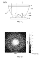
- FIGS. 7B, 7D, 7F show the light pattern images of the light-emitting apparatuses.
- the light-emitting apparatus in FIG. 7A has a light-emitting device 3000 formed on a carrier 10 , a first lens 160 covering the light-emitting device 3000 , a second lens 162 arranged on the first lens 160 , and a wavelength conversion layer 4 arranged on the second lens 162 .
- Light from the light-emitting device 3000 is firstly redirected by the first lens 160 and moves into the second lens 162 .
- the light from the first lens 160 is then redirected by the second lens 162 and moves in a direction substantially perpendicular to the carrier 10 .
- the light pattern has a brighter inner portion.
- the inner portion is substantially corresponding to the size and shape of the first lens 160 .
- the area ratio of the inner portion to the entire light pattern is substantially corresponding to the area ratio of the frontal projected areas between the first lens 160 and the second lens 162 .
- the lens 162 has a top surface connected to the wavelength conversion layer 4 , a bottom surface, side walls, and a cavity for accommodating the lens 160 and the light-emitting device 3000 .
- the cavity has a convex surface which is bulged toward the light-emitting device 3000 and has a width substantially equal to or slightly greater than that of the lens 160 .
- the side walls can inwardly approach with each other from the top surface to the bottom surface. In other words, the top surface is wider/bigger than the bottom surface in a cross section/top view.
- the side wall can be constructed by a flat surface, a curved surface, or both.
- the top surface or the bottom surface can be made in a circle, oval, rectangle, triangle, or other geometric shape. Moreover, the top surface and the bottom surface can have identical or different shapes.
- Light from the light-emitting device 3000 can be reflected and/or refracted at the side wall or the convex surface when the incident angle is varied.
- the convex surface can converge or collimate more light to the central area of the top surface of the lens 162 than to the peripheral area thereof, as shown in FIG. 7B .
- the lens 164 has a top surface connected to the wavelength conversion layer 4 , a bottom surface, side walls, and a cavity for accommodating the third lens 164 and the light-emitting device 3000 .
- the cavity has a triangular cross section with slanted edges and a bottom width. The bottom width is greater than the greatest width of the lens 160 .
- the slanted edges or surfaces can diverge more light to the peripheral area of the top surface of the lens 166 than the central area thereof, as shown in FIG. 7D .
- the fourth lens 166 has a structure similar to that of the second lens 162 .
- the lens 166 has a flat top surface connected to the wavelength conversion layer 4 , a bottom surface, side walls, and a cavity for accommodating the lens 160 and the light-emitting device 3000 .
- the cavity has a convex surface with a curvature radius smaller than that of the lens 162 .
- the light from the light-emitting device 3000 is firstly bent by the lens 160 and divergently moves into the lens 166 .
- FIG. 7E the structure similar to that of the second lens 162 .
- the light is diverged by the lens 166 , especially by the convex surface, rather than collimated in a direction substantially perpendicular to the carrier 10 , as shown in FIG. 7A .
- the light from the light-emitting device 3000 is also reflected by the sidewalls of the lens 166 .
- the light pattern shown in FIG. 7F is more uniform than that shown in FIG. 7B in light intensity distribution.
- FIG. 7G shows the forward emission light (L 1 ) and the backward emission light (L 2 ) radiated from the wavelength conversion layer 4 in the light-emitting apparatus.
- the forward emission light (L 1 ) and the backward emission light (L 2 ) can have different optical properties for different light apparatuses.
- a table showing the optical property differences between the light apparatuses shown in FIGS. 7A, 7C, and 7E is listed below.
- the difference of color temperature between the light (L 1 ) and the light (L 2 ) of the apparatus in FIG. 7A is less than 1000K
- the difference of the light extraction efficiency between the light (L 1 ) and the light (L 2 ) is larger than 10 lm/W.
- FIG. 7A FIG. 7C FIG. 7E Phosphor concentration_ 30%_ 30%/10%_ 50%_ thickness 0.5 mm 0.45 mm 0.25 mm CCT of L1 8455.27 6396.92 6568.98 CCT of L2 9813.29 11430.87 8962.41 Standard deviation of CCT between 2720.383 3487.41 1741.87 L1/L2 (K) Light extraction efficiency_L1 (lm/W) 75.3189 47.40 75.62 Light extraction efficiency _L2 (lm/W) 62.9374 87.85 65.59 Total Light extraction efficiency (lm/W) 138.256 135.25 141.21
- the wavelength conversion layer 4 in FIG. 7A has a 30% concentration of wavelength conversion material and a thickness of 0.5 mm, while that in the FIG. 7E has a 50% concentration of wavelength conversion material of 50% and a thickness of 0.25 mm.
- the wavelength conversion layer 4 in FIG. 7C has a 30% concentration of wavelength conversion material at outer portion, 10% concentration at inner portion (as shown in FIG. 7 H) and a thickness of 0.45 mm.
- the angle between the light beam from the light-emitting device and the wavelength conversion layer is not likely to affect the optical property of the light provided by the light-emitting apparatus. Referring to FIGS. 7I ⁇ 7 J, the angles between the wavelength conversion layer and three light beams are 45°, 60° and 90° respectively, as shown in FIG. 7I .
- the corresponding intensities of the three light beams, which are measured at the side of the wavelength conversion layer opposite to the light beams, are almost the same, as shown in FIG. 7J .
- FIG. 8A shows a light-emitting apparatus 1008 A with a stack including a first wavelength conversion layer 40 , a second wavelength conversion layer 42 , and a transparent layer 60 formed between the first and second wavelength conversion layers 40 , 42 .
- the optical properties of light emitted from the light-emitting apparatus 1008 A are affected by some factors of the stack. For example, the thickness of the first or second wavelength conversion layer and the weight percentage concentration (wt %) of the first or second wavelength conversion layer are all factors possibly affecting the light extraction efficiency of the light-emitting apparatus 1008 A. The light is more likely to be absorbed by the wavelength conversion layer with higher weight percentage concentration of the wavelength conversion material. The light extraction efficiency is therefore reduced when higher percentage of light is absorbed by the wavelength conversion layer.
- the stack is designed to reflect light back and forth between the first wavelength conversion layers 40 and the second wavelength conversion layer 42 before the light passing through the wavelength conversion layer 42 .
- the first wavelength conversion layer 40 has a 70% concentration.
- the second wavelength conversion layer 42 has a 5% concentration.
- the thicknesses of the first wavelength conversion layer 40 and the second wavelength conversion layer 42 are both 0.3 mm.
- the standard deviation of CCT between the forward emission light (L 1 ) and the backward emission light (L 2 ) is 2720.383 for the apparatus 1007 A in FIG.
- the apparatus 1008 A can retain the light extraction efficiency and provide a better standard deviation of CCT between the front side and back side by adopting a structure with two phosphor layers.
- the concentration of the first wavelength conversion layer 40 has higher influence on the CCT of the forward emission light (L 1 ); while the concentration of the second wavelength conversion layer 42 has higher influence on the CCT of the backward emission light (L 2 ).
- FIG. 7A FIG. 8A Phosphor concentration _ thickness 30%_ 70%/5%_ 0.5 mm 0.3 mm/0.3 mm CCT of L1 8455.27 7248.63 CCT of L2 9813.29 8114.13 Standard deviation of CCT between 2720.383 1258.146 L1/L2 (K) Light extraction efficiency_L1 (lm/W) 75.3189 66.6028 Light extraction efficiency _L2 (lm/W) 62.9374 70.4841 Total light extraction efficiency (lm/W) 138.256 137.087
- FIGS. 8C-8D show two light-emitting apparatus in accordance with embodiments of the present disclosure.
- the apparatus 1008 C in FIG. 8C includes two light-emitting devices 3000 which is arranged on two carriers 10 to emit light in a left direction and a right direction, respectively.
- the left side and the right side of the wavelength conversion layer 44 formed between the lens 170 a and 170 b , can absorb and convert light respectively coming from the two light-emitting devices 3000 .
- the two light-emitting devices 3000 can emit the same color light, such as infrared, red light, green light, blue light, and UV light.
- the CCT of the light-emitting apparatus 1008 C can be decreased down to about 6500K when the concentration of the wavelength conversion material in the wavelength conversion layer 44 is increased. However, the CCT is then kept unchanged at 6500K around when the concentration of the wavelength conversion material in the wavelength conversion layer 44 is even increased to 30% or more.
- the light extraction efficiency can be increased up to 290 (lm/W) around with the increase of the concentration of the wavelength conversion material in the wavelength conversion layer 44 . However, the light-emitting efficiency is kept unchanged around 290 (lm/W) when the concentration of the wavelength conversion material in the wavelength conversion layer 44 is even increased to 30% or more.
- the light-emitting apparatus 1008 D in FIG. 8D includes a light-emitting device 3000 positioned on the carrier 10 , two wavelength conversion layers 46 and 48 , and a lens 172 covering the light-emitting device 3000 and the wavelength conversion layers 46 and 48 .
- the lights L 1 and L 3 are redirected to incident the front side of the wavelength conversion layers 46 and 48 .
- the lights L 2 and L 4 are redirected to incident the back side of the wavelength conversion layers 46 and 48 .
- the wavelength conversion layers 46 and 48 have the same thickness of 0.55 mm.
- the lens 172 is symmetric with a central axis or a central plan (not shown), and therefore, can generate a symmetrical light paths.
- lights L 1 and L 3 are mirror images of each other; lights L 2 and L 4 are also mirror images of each other.
- the standard deviation of CCT between L 1 and L 2 , or L 3 and L 4 is less than 600K, which is less than that of the light-emitting apparatus shown in FIG. 7A .
- the light-emitting efficiency is larger than 150 lm/W, which is larger than the light-emitting efficiency of the light-emitting apparatus shown in FIG. 7A .
- FIG. 7A Phosphor concentration _ thickness 30%_ 30%_ 0.5 mm 0.5 mm CCT of L1 8455.27 6691.231 CCT of L2 9813.29 7251.631 Standard deviation of CCT between L1/L2 (K) 2720.383 548.4152
- FIGS. 9A-9D show light-emitting apparatuses in accordance with embodiments of the present disclosure.
- the lens 174 is optically coupled with a wavelength conversion layer 50 .
- the light can enter into the lens from one side and escape it at another side.
- the light can be reflected back and forth in the lens 174 if the incident angle of the light is properly controlled to create a total reflection at the top and bottom inner surfaces of the lens 174 .
- the light can be absorbed by the wavelength conversion layer 50 with strikes at different positions. With absorption of more light, more converted light can be generated by the wavelength conversion layer 50 .
- the light-emitting apparatus 1009 B has a light-emitting device 4000 formed on a carrier 10 , a lens 174 having a cavity 1740 , and a wavelength conversion layer 50 arranged on the lens 174 .
- the light-emitting device 4000 is arranged in the cavity 1740 and fully covered by the lens 174 .
- FIG. 9C shows a light pattern viewed on a front side of the lens 174 .
- FIG. 9D shows a light pattern viewed on a bottom side of the lens 174 .
- the optical properties of the apparatus 1009 B are listed below, wherein the standard deviation of CCT between light L 1 and L 2 is lower than 200K, the total light extraction efficiency is around 140 lm/W.
- FIG. 7A FIG. 9B Phosphor concentration _ thickness 30%_ 24%_ 0.5 mm 0.45 mm CCT of L1 8455.27 6593.7 CCT of L2 9813.29 6292.65 Standard deviation of CCT between L1/L2 (K) 2720.383 160.89
- FIGS. 10A-10D show a light-emitting apparatus in accordance with embodiments of the present disclosure.
- the light is reflected back and forth in the lens 176 .
- the lens 176 has a first wing 1760 and a second wing 1762 which are inclined against the carrier 10 by angles ⁇ 1 and ⁇ 2 , respectively.
- the angle ⁇ 1 is 30°, which is equal to that of ⁇ 2 .
- the light L 1 is reflected two or more times within the second wing 1762 before passing through the wavelength conversion layer 52 .
- the light L 2 is reflected two or more times within the second wing 1762 and can leave the second wing 1762 towards a direction far away from the wavelength conversion layer 52 without passing through the wavelength conversion layer 52 .
- the wavelength conversion layer 52 is not only formed on the surfaces S 1 and S 2 between the first wing 1760 and second wing 1762 but also on the edges E 1 and E 2 of the first wing 1760 and second wing 1762 .
- the first wing 1760 and second wing 1762 are bifurcated above the light-emitting device 5000 in a V/U-like shape.
- the lights L 1 and L 3 are moving in similar paths as shown in the drawing. With adopting lens shown in FIGS.
- the light-emitting apparatus in FIG. 10B has a light-emitting device 5000 formed on a carrier 10 , a lens 176 having a first wing 1760 and second wing 1762 , and a wavelength conversion layer 52 .
- FIG. 10C shows a front image of the lens 176 .
- FIG. 10D shows bottom image of the lens 176 .
- the optical properties of the apparatus are listed below, wherein the standard deviation of CCT is lower than 700K and the total light extraction efficiency is larger than 150 lm/W.
- FIG. 7A Phosphor concentration _ thickness 30%_ 4%_ 0.5 mm 0.5 mm CCT of L1 8455.27 6342.11 CCT of L2 9813.29 7416.94 Standard deviation of CCT between L1/L2 (K) 2720.383 657.92 Light extraction efficiency_L1 (lm/W) 75.3189 77.5 Light extraction efficiency _L2 (lm/W) 62.9374 80.87 Total light extraction efficiency (lm/W) 138.256 158.37
- the apparatus has several light-emitting devices 6000 (five devices 6000 are shown in the drawing, but the number can be less or more), a diffusion layer 18 distant from the light-emitting devices 6000 , a prism layer 20 on the diffusion layer 18 , and an liquid crystal display (LCD) module 22 on the prism layer 20 .
- the light-emitting devices 6000 , the diffusion layer 18 , and prism layer 20 can be integrated into a backlight module of LCD display.
- the LCD module 22 has a lens.
- the diffusion layer 18 can redistribute light from the light-emitting devices 6000 , and increase the light uniformity of the light-emitting devices 6000 .
- the prism layer 20 has numerous lenses to concentrate light. The light uniformity of the LCD module 22 is therefore increased.
- the distance between the lens in the LCD module 22 and the light-emitting device 6000 is larger than that between the adjacent light-emitting devices.
- FIG. 11B shows a schematic view of the apparatus.
- the symbol H represents the distance between the light-emitting device 6000 and the LCD module 22
- the symbol R represents the radius of the light field showing on the LCD module 22 .
- the symbol d represents the lateral distance between adjacent light-emitting devices.
- the shorter H implies a smaller light field with a shorter radius R at the LCD module 22 .
- the light-emitting device 6000 provides a light field on the LCD module 22 (or on the lens) having a radius R two or more times larger than the distance d.
- the FIGS. 11C-11D show a schematic top view of the arrangement of the light-emitting devices 6000 .
- the light-emitting devices 6000 are arranged in a connected rectangular shape, as shown in FIG. 11C .
- the light-emitting devices 6000 are arranged in a connected triangular shape, as shown in FIG. 11D .
- Different arrangements of the light-emitting devices can provide different illumination distribution.
- FIG. 11E shows an illumination distribution image of a unit area of the array shown in FIG. 11C .
- FIG. 11F shows an illumination distribution image of a unit area of the array shown in FIG. 11D .
- the radius R of the light field of a single light-emitting device 6000 can be set equal to the shortest distance between two adjacent light-emitting devices 6000 .
- different colors represent different illuminance level. The detail of the color mapping can be referred to the legend of respective diagram.
- FIG. 11G is a diagram showing that the uniformity of illumination varies with a displacement of a light-emitting device 6000 in x direction.
- FIG. 11H is another diagram showing that the uniformity of the illumination varies with a displacement of a light-emitting device 6000 in y direction.
- the abscissa of the FIG. 11G or FIG. 11H represents the displacement of one light-emitting device 6000 with respect to an original position in the light-emitting apparatus.
- the ordinate of the FIG. 11G or FIG. 11H represents the normalized uniformity of illuminance of a light-emitting apparatus. As shown in FIGS.
- the positive (x>0 or y>0) and negative (x ⁇ 0 or y ⁇ O) displacements result in similar decreasing levels of illumination uniformities in the rectangular arrangement.
- the positive (x>0 or y>0) and negative (x ⁇ 0 or y ⁇ 0) displacements result in different decreasing levels of illumination uniformities in the triangle arrangement.
- the negative displacement results in a more rapid drop in the illumination uniformity than the positive displacement does.
- the illuminance uniformity is substantially lower than 0.9 when the absolute value of the displacement is about 0.1 mm.
- FIGS. 12A-12B show measuring instruments in accordance with embodiments of the present disclosure.
- the instrument in FIG. 12A can measure the light properties of a light-emitting device 7000 in far-field.
- the light from the light-emitting device 7000 can pass through a first iris 178 a and a second iris 178 b and be received by a spectrometer 24 .
- the first iris 178 a and the second iris 178 b can remove part of the light and retain light in a specific angle to be detected by the spectrometer 24 .
- the instrument in FIG. 12B can measure the light properties of a light-emitting device 7000 in mid-field.
- the light from the light-emitting device 7000 can pass through a convex lens 180 and be received by the spectrometer 24 .
- FIGS. 12C-12E show some results measured by the instrument shown in FIG. 12A .
- 0 degree in FIGS. 12C-12E substantially corresponds to the center of the light-emitting device 7000 .
- the angle represents the angle between the measuring point and the center of the light-emitting device 7000 .
- FIG. 12C shows the normalized intensities of blue light, yellow light, and total light. The total light can include the blue light, the yellow light, or other color light. As shown in the drawing, different lights have different intensities at the same angle.
- FIG. 12D shows the light intensity ratio of the yellow light to the blue light (YBR). The ratio increases with the increase of absolute value of the angle.
- the correlated color temperature (CCT) decreases from over 6500K at 0 degree (around the center of the light-emitting device) to about 4500K at 90 degree (around the peripheral region of the light-emitting device).
- a lens 184 can be arranged on the light-emitting device 8000 to render a more uniform illuminance and/or color distribution.
- the lens 184 can direct the blue light to a direction with a larger angle and the yellow light to a direction with a smaller angle.
- the lens 184 has a main body and a cavity 1840 which is built from a bottom surface of the main body and defines a space for accommodating the light-emitting device 8000 .
- the cavity 1840 has a top inner surface with a bell/dome-like shape/contour and a bottom inner surface with a tail extending to the bottom surface of the lens 1840 in a cross-sectional view.
- the top inner surface and the bottom inner surface can have identical or different curvatures.
- the lens 184 has an outer contour with several sections connected with each other (the section can be seen as a line in a cross sectional view, as shown in FIG. 13 ).
- the transition portion of two adjacent sections preferably has a perceived angular change to redirect specific color light to a predetermined direction.
- the color light with shorter wavelength such as a blue light
- the color light with longer wavelength such as a yellow light
Abstract
The present application discloses a light-emitting apparatus having a light-emitting device and a wavelength conversion layer. The light-emitting device has a first top surface and a first side surface, and the wavelength conversion layer has a second top surface and a second side surface and covers the first top surface. A ratio of a distance between the first top surface to the second top surface and a distance between the first side surface and the second side surface is between 1.1˜1.3.
Description
This application claims the benefit of U.S. Provisional Application, Ser. No. 62/029,977, filed on Jul. 28, 2014. The Provisional Application and its English translation are incorporated herein by reference in their entirety.
Technical Field
The present disclosure relates to a light-emitting apparatus and in particular to a light-emitting apparatus having a semiconductor light-emitting element and an optical element.
Description of the Related Art
A light-emitting device having light-emitting diode (LED) is gradually taking the place of traditional incandescent light for energy saving, environmental protection, long operation life, compact, and so on.
Various kinds of optical elements, such as lens, reflector, and wavelength converter, can be used to change the optical properties of the light-emitting device. The lens can be used to collect or redistribute light from LEDs. The reflector can redirect light from LEDs to a desired direction. Moreover, the wavelength converter, such as phosphor, dye, or quantum dot, can convert color light from LEDs to another one.
The present application discloses a light-emitting apparatus having a light-emitting device and a wavelength conversion layer. The light-emitting device has a first top surface and a first side surface, and the wavelength conversion layer has a second top surface and a second side surface and covers the first top surface. A ratio of a distance between the first top surface to the second top surface and a distance between the first side surface and the second side surface is between 1.1˜1.3.
A light-emitting apparatus has a light-emitting device, a wavelength conversion layer covering the light-emitting device, a first lens on the light-emitting device, a second lens on the first lens, and a wavelength conversion layer connected to the second lens. The first lens ha a top surface bent in a first direction, and the second lens has an inner surface bent in a second direction which is different from the first direction.
A light-emitting apparatus has a first light-emitting device, a second light-emitting devices spaced from first light-emitting device by a first distance, a diffusion layer covering the first and second light-emitting devices, a prism layer on the diffusion layer, and an LCD module on the prism layer. The first light-emitting device or the second light-emitting device is configured to provide a light field on the LCD module and having a radius two or more times larger than the first distance.
The drawings illustrate the embodiments of the disclosure and, together with the description, serve to illustrate the principles of the application. The same name or the same reference numeral given or appeared in different paragraphs or figures along the specification can has the same or equivalent meaning(s) while it is once defined anywhere of the disclosure. The thickness or the shape of an element in the specification can be expanded or narrowed.
The light-emitting device 1000C has a transparent cover 8 formed on the wavelength conversion layer 4. The light-emitting device 1000D has a transparent cover 8, a wavelength conversion layer 4, a transparent layer 6 and a light-emitting diode 2 stacked in sequence from top to bottom. The wavelength conversion layer 4 of the light-emitting device 1000D has a bottom surface with a contour identical or similar to that of a top surface of the transparent layer 6, and a top surface with a contour identical or similar to that of a bottom surface of the transparent cover 8. Moreover, the top and bottom surfaces of the wavelength conversion layer 4 of the light-emitting device 1000D can have identical or different contours. The wavelength conversion layer 4 of the light-emitting device 1000D has two surfaces (top and bottom surfaces) parallel to each other. The wavelength conversion layer 4 of the light-emitting device 1000E is formed on the transparent layer 6 and has a bottom surface close to the transparent layer 6 and with a contour identical or similar to the top surface of the transparent layer 6, and a top surface formed in a flat contour or parallel to a top surface of the light-emitting device 1000E or the transparent cover 8. The wavelength conversion layer 4 of the light-emitting device 1000E has a bottom surface stretching along the contour of the light-emitting diode 2 and a flat top surface.
The light-emitting device 1000F has a transparent layer 6 which covers the top surface and side surfaces of the light-emitting diode 2. In one embodiment, the outer surfaces of the transparent layer 6 are respectively parallel to the inner surfaces of the transparent layer 6. In other words, the transparent layer 6 has a uniform thickness.
The light-emitting device 1000G has a transparent layer 6 which covers the top surface and side surfaces of the light-emitting diode 2. A wavelength conversion layer 4 covers the top surface and side surfaces of transparent layer 6. A transparent cover 8 having a rectangular cross-section is formed on the top surface of the wavelength conversion layer 4. The wavelength conversion layer 4 has a top thickness at the top of the light-emitting diode 2 and a lateral thickness at the lateral of the light-emitting diode 2. The lateral thickness is greater than the top thickness.
The light-emitting diode 2 has an active layer to emit an incoherent light. The light emitted from the light-emitting diode 2 has a first light intensity, a first light field, and a first color. The wavelength conversion layer 4 has a wavelength conversion material having a particle size ranged between 8˜50 μm, such as 8, 17, 20, 32 or 46 μm. The particle size can be a diameter or a characteristic length. The transparent layer 6 and the transparent cover 8 have transparent material. At least 60% of the light emitted from the light-emitting diode 2 can pass through the transparent layer 6 or the transparent cover 8 without being absorbed, i.e. the transparent layer 6 or the transparent cover 8 has a 60% transparency to the light from the light-emitting diode 2. The light-emitting devices 1000A˜1000H can emit a light having a second light intensity, a second light field, and a second color. The second light intensity is smaller than the first light intensity, due to part of the light form the light-emitting diode 2 is absorbed by or trapped in the wavelength conversion layer 4, the transparent layer 6 or the transparent cover 8. The second light field can be identical with or different from the first light field. Diffusion particles can be added to the transparent layer 6 or the transparent cover 8 to scatter light and change light field. The light path in the aforementioned embodiments can be visualized by adopting an appropriate simulation model, such as Monte Carlo ray tracing method. The light propagation within the wavelength conversion layer 4 can be visualized by using a simulation model based on Mie Scattering theory.
Referring to FIGS. 1B and 1D , the transparent layer 6 has a curved contour. The curved contour is convexly bent on the top surface of the light-emitting diode 2. The wavelength conversion layer 4 is formed on the curved top surface of the transparent layer 6 and therefore has a concavely-bent bottom surface. The transparent layer 6 further has a lower surface which has a contour similar to the shape of the light-emitting diode 2. Referring to FIGS. 1F, 1G and 1H , the transparent layer 6 and the wavelength conversion layer 4substantially have reversed-U shapes. Referring to FIG. 1H , the transparent cover 8 also has a reversed-U shape, while the reversed-U shape has a top portion and a lateral portion with is thinner than the top portion.
Referring to FIG. 5B , the color space uniformity Δu′v′ is about of 0.002, and the color temperature variance ΔCCT is about 100K, when the distance H is about 750 μm and the size of the light-emitting device is in a square of 1.8×1.8 mm2. The light extraction efficiency is larger than 135 lm/Watt when the distance H is about 750 μm and the size of the light-emitting device is a square of 2×2 mm2. The light-emitting device in FIG. 5B has better optical properties, such as light extraction efficiency, color space uniformity Δu′v′ and color temperature variance ΔCCT, when the distance H is 350 μm and size is of 1.2×1.2 mm2 or when the distance H is 450 μm and size is of 1.2×1.2 mm2.
Compared with structure of light-emitting device in FIG. 5B , the light-emitting device in FIG. 5C has better optical properties, such as light extraction efficiency, color space uniformity Δu′v′ and color temperature variance ΔCCT, when the distance H is 350 μm and size of 1.2×1.2 mm2, when the distance H is 450 μm and size of 1.2×1.2 mm2, or when the distance H is 750 μm and size of 1.4×1.4 mm2. The light provided by light-emitting devices in FIGS. 5A ˜5C has better performance at a specific sizes of distance H and distance W. For example, the color space uniformity Δu′v′ is better with a ratio, HWR (HWR=H/W), between 1.1˜1.3, and the light has a color space uniformity Δu′v′ within four MacAdam ellipse when the HWR is larger than 0.7.
Provided the light-emitting devices shown in either of FIGS. 5A ˜5C can be arranged on the carrier 10 shown in FIG. 3A , and the light provided by the light-emitting devices in FIG. 5A ˜5C are affected by the top surface 100. For example, when the direct reflectance of the top surface 100 decreases from 100% around to 90%, the light extraction efficiency can decrease by 18.42%, 18.13% and 20.28%. In another embodiment, when the top surface 100 changes from a surface having a reflectance of about 100% to a Lambertian surface of about 90% reflectance, the light extraction efficiency of the light-emitting apparatus decrease by 11.56%, 12.14% and 11.93%. In another embodiment, when the color temperature of the light emitted from the light-emitting device changes from 6500K to 30000K, the light extraction efficiency of the light-emitting devices in FIGS. 5A ˜5C can decrease by 7.63%, 7.58% and 6.22%. The properties of light emitted from the structures in FIGS. 1, 3A-3B, 4A-4C or 5A-5C are affected by the size of wavelength conversion layer 4, the size of total structure, the reflective rate of the top surface 100, or the color temperature of the light emitted from the light-emitting device.
As shown in FIGS. 3A ˜3E, the light extraction efficiency is not greatly affected by the reflectance of the surface of the sidewalls, no matter the surface is a Lambertian surface or a surface having about 100% reflectivity. As shown in FIGS. 1A ˜1H, 4A˜4C, 5A˜5C and 6A˜6F, the light extraction efficiency is more likely affected by the reflectance of the surface of the carrier 10 or the sizes of the light-emitting device. For example, the higher reflectance of the surface of the carrier 10 can improve light extraction efficiency by about 18%˜20%. Or, a reflective layer can be formed between the carrier 10 and the light-emitting device to improve light extraction efficiency by about 11%˜12%. Moreover, the light-emitting devices having similar color space uniformity can have improved light extraction efficiencies by increasing the size of the light-emitting devices. For example, when the size of the light-emitting device is increased to 25 times, or more, larger than the size of the light-emitting diode, the light extraction efficiency of the light-emitting device is increased from 127 lm/W to 138 lm/W, which is substantially equal to an 8% increase.
Besides, the ratio, HWR, or the particles 3 within the structures can affect the uniformity of light form the light-emitting device. For example, the color space uniformity Δu′v′ over the angle is less than 0.04 when the HWR is between 1.1˜1.3. The color space uniformity Δu′v′ over the angle between −80°˜+80° is less than 0.01 when the concentration of the particles 3 in the structure is about 5%.
The light-emitting apparatus in FIG. 7A has a light-emitting device 3000 formed on a carrier 10, a first lens 160 covering the light-emitting device 3000, a second lens 162 arranged on the first lens 160, and a wavelength conversion layer 4 arranged on the second lens 162. Light from the light-emitting device 3000 is firstly redirected by the first lens 160 and moves into the second lens 162. The light from the first lens 160 is then redirected by the second lens 162 and moves in a direction substantially perpendicular to the carrier 10. As shown in FIG. 7B , the light pattern has a brighter inner portion. The inner portion is substantially corresponding to the size and shape of the first lens 160. The area ratio of the inner portion to the entire light pattern is substantially corresponding to the area ratio of the frontal projected areas between the first lens 160 and the second lens 162.
In detail, as shown in FIG. 7A , the lens 162 has a top surface connected to the wavelength conversion layer 4, a bottom surface, side walls, and a cavity for accommodating the lens 160 and the light-emitting device 3000. The cavity has a convex surface which is bulged toward the light-emitting device 3000 and has a width substantially equal to or slightly greater than that of the lens 160. The side walls can inwardly approach with each other from the top surface to the bottom surface. In other words, the top surface is wider/bigger than the bottom surface in a cross section/top view. The side wall can be constructed by a flat surface, a curved surface, or both. In some embodiments, the top surface or the bottom surface can be made in a circle, oval, rectangle, triangle, or other geometric shape. Moreover, the top surface and the bottom surface can have identical or different shapes. Light from the light-emitting device 3000 can be reflected and/or refracted at the side wall or the convex surface when the incident angle is varied. The convex surface can converge or collimate more light to the central area of the top surface of the lens 162 than to the peripheral area thereof, as shown in FIG. 7B .
As shown in FIG. 7C , most of light from the light-emitting device 3000 is redirected to the edge or rim of the third lens 164 after refracting by the first lens 160 and refracting and reflecting by the third lens 164. Consequently, as shown in FIG. 7D , the edge or rim of light pattern is brighter than the inner portion.
In detail, as shown in FIG. 7C , the lens 164 has a top surface connected to the wavelength conversion layer 4, a bottom surface, side walls, and a cavity for accommodating the third lens 164 and the light-emitting device 3000. The cavity has a triangular cross section with slanted edges and a bottom width. The bottom width is greater than the greatest width of the lens 160. In some embodiments, the slanted edges or surfaces can diverge more light to the peripheral area of the top surface of the lens 166 than the central area thereof, as shown in FIG. 7D .
As shown in FIG. 7E , the fourth lens 166 has a structure similar to that of the second lens 162. In detail, as shown in FIG. 7E , the lens 166 has a flat top surface connected to the wavelength conversion layer 4, a bottom surface, side walls, and a cavity for accommodating the lens 160 and the light-emitting device 3000. The cavity has a convex surface with a curvature radius smaller than that of the lens 162. The light from the light-emitting device 3000 is firstly bent by the lens 160 and divergently moves into the lens 166. Compared with the structure shown in FIG. 7A , the light is diverged by the lens 166, especially by the convex surface, rather than collimated in a direction substantially perpendicular to the carrier 10, as shown in FIG. 7A . Besides, the light from the light-emitting device 3000 is also reflected by the sidewalls of the lens 166.The light pattern shown in FIG. 7F is more uniform than that shown in FIG. 7B in light intensity distribution.
| light emitting apparatus | FIG. 7A | FIG. 7C | FIG. 7E |
| Phosphor concentration_ | 30%_ | 30%/10%_ | 50%_ |
| thickness | 0.5 mm | 0.45 mm | 0.25 mm |
| CCT of L1 | 8455.27 | 6396.92 | 6568.98 |
| CCT of L2 | 9813.29 | 11430.87 | 8962.41 |
| Standard deviation of CCT between | 2720.383 | 3487.41 | 1741.87 |
| L1/L2 (K) | |||
| Light extraction efficiency_L1 (lm/W) | 75.3189 | 47.40 | 75.62 |
| Light extraction efficiency _L2 (lm/W) | 62.9374 | 87.85 | 65.59 |
| Total Light extraction efficiency (lm/W) | 138.256 | 135.25 | 141.21 |
The wavelength conversion layer 4 in FIG. 7A has a 30% concentration of wavelength conversion material and a thickness of 0.5 mm, while that in the FIG. 7E has a 50% concentration of wavelength conversion material of 50% and a thickness of 0.25 mm. The wavelength conversion layer 4 in FIG. 7C has a 30% concentration of wavelength conversion material at outer portion, 10% concentration at inner portion (as shown in FIG. 7 H) and a thickness of 0.45 mm. In an embodiment, the angle between the light beam from the light-emitting device and the wavelength conversion layer is not likely to affect the optical property of the light provided by the light-emitting apparatus. Referring to FIGS. 7I ˜7J, the angles between the wavelength conversion layer and three light beams are 45°, 60° and 90° respectively, as shown in FIG. 7I . The corresponding intensities of the three light beams, which are measured at the side of the wavelength conversion layer opposite to the light beams, are almost the same, as shown in FIG. 7J .
| light emitting apparatus | FIG. 7A | FIG. 8A |
| Phosphor concentration _ thickness | 30%_ | 70%/5%_ |
| 0.5 mm | 0.3 mm/0.3 mm | |
| CCT of L1 | 8455.27 | 7248.63 |
| CCT of L2 | 9813.29 | 8114.13 |
| Standard deviation of CCT between | 2720.383 | 1258.146 |
| L1/L2 (K) | ||
| Light extraction efficiency_L1 (lm/W) | 75.3189 | 66.6028 |
| Light extraction efficiency _L2 (lm/W) | 62.9374 | 70.4841 |
| Total light extraction efficiency (lm/W) | 138.256 | 137.087 |
The light-emitting apparatus 1008D in FIG. 8D includes a light-emitting device 3000 positioned on the carrier 10, two wavelength conversion layers 46 and 48, and a lens 172 covering the light-emitting device 3000 and the wavelength conversion layers 46 and 48. Referring to FIG. 8D , the lights L1 and L3 are redirected to incident the front side of the wavelength conversion layers 46 and 48. The lights L2 and L4 are redirected to incident the back side of the wavelength conversion layers 46 and 48. In an embodiment, the wavelength conversion layers 46 and 48 have the same thickness of 0.55 mm.
The light properties of the light-emitting apparatus are listed below. The lens 172 is symmetric with a central axis or a central plan (not shown), and therefore, can generate a symmetrical light paths. In other words, lights L1 and L3 are mirror images of each other; lights L2 and L4 are also mirror images of each other. The standard deviation of CCT between L1 and L2, or L3 and L4 is less than 600K, which is less than that of the light-emitting apparatus shown in FIG. 7A . The light-emitting efficiency is larger than 150 lm/W, which is larger than the light-emitting efficiency of the light-emitting apparatus shown in FIG. 7A .
| light emitting apparatus | FIG. 7A | FIG. 8D |
| Phosphor concentration _ thickness | 30%_ | 30%_ |
| 0.5 mm | 0.5 mm | |
| CCT of L1 | 8455.27 | 6691.231 |
| CCT of L2 | 9813.29 | 7251.631 |
| Standard deviation of CCT between L1/L2 (K) | 2720.383 | 548.4152 |
| Light extraction efficiency_L1 (lm/W) | 75.3189 | 62.67172 |
| Light extraction efficiency _L2 (lm/W) | 62.9374 | 96.07058 |
| Total light extraction efficiency (lm/W) | 138.256 | 158.7423 |
As shown in FIG. 9B , the light-emitting apparatus 1009B has a light-emitting device 4000 formed on a carrier 10, a lens 174 having a cavity 1740, and a wavelength conversion layer 50 arranged on the lens 174. The light-emitting device 4000 is arranged in the cavity 1740 and fully covered by the lens 174. FIG. 9C shows a light pattern viewed on a front side of the lens 174. FIG. 9D shows a light pattern viewed on a bottom side of the lens 174. The optical properties of the apparatus 1009B are listed below, wherein the standard deviation of CCT between light L1 and L2 is lower than 200K, the total light extraction efficiency is around 140 lm/W.
| light emitting apparatus | FIG. 7A | FIG. 9B |
| Phosphor concentration _ thickness | 30%_ | 24%_ |
| 0.5 mm | 0.45 mm | |
| CCT of L1 | 8455.27 | 6593.7 |
| CCT of L2 | 9813.29 | 6292.65 |
| Standard deviation of CCT between L1/L2 (K) | 2720.383 | 160.89 |
| Light extraction efficiency _L1 (lm/W) | 75.3189 | 61.76 |
| Light extraction efficiency _L2 (lm/W) | 62.9374 | 73.42 |
| Total light extraction efficiency (lm/W) | 138.256 | 135.18 |
| light emitting apparatus | FIG. 7A | FIG. 10B |
| Phosphor concentration _ thickness | 30%_ | 4%_ |
| 0.5 mm | 0.5 mm | |
| CCT of L1 | 8455.27 | 6342.11 |
| CCT of L2 | 9813.29 | 7416.94 |
| Standard deviation of CCT between L1/L2 (K) | 2720.383 | 657.92 |
| Light extraction efficiency_L1 (lm/W) | 75.3189 | 77.5 |
| Light extraction efficiency _L2 (lm/W) | 62.9374 | 80.87 |
| Total light extraction efficiency (lm/W) | 138.256 | 158.37 |
Referring to FIG. 11A , the apparatus has several light-emitting devices 6000 (five devices 6000 are shown in the drawing, but the number can be less or more), a diffusion layer 18 distant from the light-emitting devices 6000, a prism layer 20 on the diffusion layer 18, and an liquid crystal display (LCD) module 22 on the prism layer 20.The light-emitting devices 6000, the diffusion layer 18, and prism layer 20 can be integrated into a backlight module of LCD display. The LCD module 22 has a lens. The diffusion layer 18 can redistribute light from the light-emitting devices 6000, and increase the light uniformity of the light-emitting devices 6000. The prism layer 20 has numerous lenses to concentrate light. The light uniformity of the LCD module 22 is therefore increased. In an embodiment, the distance between the lens in the LCD module 22 and the light-emitting device 6000 is larger than that between the adjacent light-emitting devices.
As shown in FIG. 13 , a lens 184 can be arranged on the light-emitting device 8000 to render a more uniform illuminance and/or color distribution. The lens 184 can direct the blue light to a direction with a larger angle and the yellow light to a direction with a smaller angle. The lens 184 has a main body and a cavity 1840 which is built from a bottom surface of the main body and defines a space for accommodating the light-emitting device 8000. The cavity 1840 has a top inner surface with a bell/dome-like shape/contour and a bottom inner surface with a tail extending to the bottom surface of the lens 1840 in a cross-sectional view. The top inner surface and the bottom inner surface can have identical or different curvatures. Moreover, the top inner surface itself or the bottom inner surface itself can have one or more curvatures. The lens 184 has an outer contour with several sections connected with each other (the section can be seen as a line in a cross sectional view, as shown in FIG. 13 ). The transition portion of two adjacent sections preferably has a perceived angular change to redirect specific color light to a predetermined direction. For example, the color light with shorter wavelength, such as a blue light, can be bended downward after striking a higher section of the lens 184; the color light with longer wavelength, such as a yellow light, can be bended upward after striking the a lower section portion of the lens 184.
1. It will be apparent to those having ordinary skill in the art that various modifications and variations can be made to the devices in accordance with the present disclosure without departing from the scope or spirit of the disclosure. In view of the foregoing, it is intended that the present disclosure covers modifications and variations of this disclosure provided they fall within the scope of the following claims and their equivalents.
Claims (9)
1. A light-emitting apparatus, comprising:
a light-emitting diode, comprising a first top surface and a first side surface; and
an outmost transparent cover covering the first top surface and having a second top surface and a second side surface,
wherein a ratio of a distance between the first top surface and the second top surface to a distance between the first side surface and the second side surface is between 1.1-1.3.
2. The light-emitting apparatus according to claim 1 , further comprising a transparent layer formed between the light-emitting diode and the transparent cover.
3. The light-emitting apparatus according to claim 1 , further comprising a carrier having a third top surface connected to a bottom side, which is opposite to the first top surface.
4. The light-emitting apparatus according to claim 3 , wherein the third top surface is a Lambertian scattering surface.
5. The light-emitting apparatus according to claim 1 , further comprising a lens arranged on the light-emitting diode, wherein the lens comprises a first wing and a second wing.
6. A light-emitting apparatus, comprising:
a light-emitting device;
a wavelength conversion layer covering the light-emitting device and having wavelength particles;
a first lens, having a top surface bent in a first direction, on the light-emitting device; and
a second lens, connected to the wavelength conversion layer, and having an inner surface bent in a second direction on the first lens,
wherein the first direction is different from the second direction, and
wherein the light-emitting apparatus has a first light extraction efficiency in the first direction and a second light extraction efficiency in the second direction, a difference between the first light extraction efficiency and the second light extraction efficiency is larger than 10 lm/W.
7. The light-emitting apparatus according to claim 6 , wherein the light-emitting apparatus is configured to provide a first optical property in the first direction and a second optical property different from the first optical property in the second direction.
8. The light-emitting apparatus according to claim 7 , wherein a difference between the first optical property and the second optical property is a color temperature difference less than 1000K.
9. The light-emitting apparatus according to claim 6 , wherein the wavelength conversion layer comprises a first wavelength conversion layer, a second wavelength conversion layer and a transparent layer, the transparent layer has a solid material and is sandwiched by the first wavelength conversion layer and the second wavelength conversion layer.
Priority Applications (7)
| Application Number | Priority Date | Filing Date | Title |
|---|---|---|---|
| US14/810,180 US9911907B2 (en) | 2014-07-28 | 2015-07-27 | Light-emitting apparatus |
| TW108113852A TWI728348B (en) | 2014-07-28 | 2015-07-28 | Light-emitting apparatus |
| CN201510450634.1A CN105318278B (en) | 2014-07-28 | 2015-07-28 | Luminescence component |
| CN201910879067.XA CN110578912B (en) | 2014-07-28 | 2015-07-28 | Light emitting assembly |
| TW104124413A TWI661581B (en) | 2014-07-28 | 2015-07-28 | Light-emitting apparatus |
| US15/913,865 US20180198039A1 (en) | 2014-07-28 | 2018-03-06 | Light-emitting apparatus |
| US16/895,807 US11165000B2 (en) | 2014-07-28 | 2020-06-08 | Light-emitting apparatus |
Applications Claiming Priority (2)
| Application Number | Priority Date | Filing Date | Title |
|---|---|---|---|
| US201462029977P | 2014-07-28 | 2014-07-28 | |
| US14/810,180 US9911907B2 (en) | 2014-07-28 | 2015-07-27 | Light-emitting apparatus |
Related Child Applications (1)
| Application Number | Title | Priority Date | Filing Date |
|---|---|---|---|
| US15/913,865 Continuation US20180198039A1 (en) | 2014-07-28 | 2018-03-06 | Light-emitting apparatus |
Publications (2)
| Publication Number | Publication Date |
|---|---|
| US20160056348A1 US20160056348A1 (en) | 2016-02-25 |
| US9911907B2 true US9911907B2 (en) | 2018-03-06 |
Family
ID=55349017
Family Applications (3)
| Application Number | Title | Priority Date | Filing Date |
|---|---|---|---|
| US14/810,180 Active 2035-08-19 US9911907B2 (en) | 2014-07-28 | 2015-07-27 | Light-emitting apparatus |
| US15/913,865 Abandoned US20180198039A1 (en) | 2014-07-28 | 2018-03-06 | Light-emitting apparatus |
| US16/895,807 Active US11165000B2 (en) | 2014-07-28 | 2020-06-08 | Light-emitting apparatus |
Family Applications After (2)
| Application Number | Title | Priority Date | Filing Date |
|---|---|---|---|
| US15/913,865 Abandoned US20180198039A1 (en) | 2014-07-28 | 2018-03-06 | Light-emitting apparatus |
| US16/895,807 Active US11165000B2 (en) | 2014-07-28 | 2020-06-08 | Light-emitting apparatus |
Country Status (2)
| Country | Link |
|---|---|
| US (3) | US9911907B2 (en) |
| TW (2) | TWI661581B (en) |
Families Citing this family (6)
| Publication number | Priority date | Publication date | Assignee | Title |
|---|---|---|---|---|
| JP6339053B2 (en) * | 2014-09-30 | 2018-06-06 | 富士フイルム株式会社 | Wavelength conversion member, backlight unit including the same, and liquid crystal display device |
| US20180323354A1 (en) * | 2017-05-07 | 2018-11-08 | Yang Wang | Light emitting device and method for manufacturing light emitting device |
| KR20200041958A (en) * | 2018-10-04 | 2020-04-22 | 칸툼 우시카타 씨오., 엘티디. | Optical system device, biconvex lens |
| TWM607954U (en) * | 2020-06-30 | 2021-02-21 | 光森科技有限公司 | Light source module |
| CN214375712U (en) | 2020-06-30 | 2021-10-08 | 光森科技有限公司 | Light source module |
| TWI801848B (en) | 2021-04-23 | 2023-05-11 | 元太科技工業股份有限公司 | Reflective display and white light source thereof |
Citations (11)
| Publication number | Priority date | Publication date | Assignee | Title |
|---|---|---|---|---|
| US20060114369A1 (en) * | 2003-02-19 | 2006-06-01 | Lee Jeong-Hwan | Liquid crystal display apparatus |
| US20080029775A1 (en) * | 2006-08-02 | 2008-02-07 | Lustrous Technology Ltd. | Light emitting diode package with positioning groove |
| US20080100774A1 (en) * | 2006-10-31 | 2008-05-01 | Samsung Electronics Co., Ltd. | Light source device and liquid crystal display device having the same |
| US20080230795A1 (en) * | 2007-03-20 | 2008-09-25 | Eric W B Dias | Light emitting diode |
| US20100061087A1 (en) * | 2007-03-05 | 2010-03-11 | Sharp Kabushiki Kaisha | Backlight and display |
| US7942556B2 (en) * | 2007-06-18 | 2011-05-17 | Xicato, Inc. | Solid state illumination device |
| US20110193118A1 (en) * | 2010-02-09 | 2011-08-11 | Oshima Yukitoyo | Light emitting device and manufacturing method thereof |
| US20130027946A1 (en) * | 2011-07-29 | 2013-01-31 | Taiwan Semiconductor Manufactruring Company, Ltd. | Wide angle based indoor lighting lamp |
| US20130099661A1 (en) * | 2011-10-18 | 2013-04-25 | Commissariat A L'energie Atomique Et Aux Energies Alternatives | Light emitting diode component |
| US8434887B2 (en) * | 2009-08-27 | 2013-05-07 | Dolby Laboratories Licensing Corporation | Optical mixing and shaping system for display backlights and displays incorporating the same |
| US20140131749A1 (en) * | 2012-11-14 | 2014-05-15 | Epistar Corporation | Lighting apparatuses and driving methods regarding to light-emitting diodes |
Family Cites Families (36)
| Publication number | Priority date | Publication date | Assignee | Title |
|---|---|---|---|---|
| US7072096B2 (en) * | 2001-12-14 | 2006-07-04 | Digital Optics International, Corporation | Uniform illumination system |
| CN100583578C (en) * | 2002-03-08 | 2010-01-20 | 夏普株式会社 | Light source apparatus and optical communication module comprising it |
| US7121690B1 (en) * | 2004-02-26 | 2006-10-17 | Advanced Optical Technologies, Llc | Constructive occlusion with a transmissive component |
| TWI241038B (en) * | 2004-09-14 | 2005-10-01 | Ind Tech Res Inst | Light emitting diode structure and fabrication method thereof |
| KR100616625B1 (en) * | 2004-10-20 | 2006-08-28 | 삼성전기주식회사 | Large size backlight apparatus reduced in thickness |
| CN101086577A (en) | 2006-06-07 | 2007-12-12 | 中国科学院半导体研究所 | LCD backlight source structure of LED illumination |
| US7804147B2 (en) * | 2006-07-31 | 2010-09-28 | Cree, Inc. | Light emitting diode package element with internal meniscus for bubble free lens placement |
| KR100828900B1 (en) * | 2006-09-04 | 2008-05-09 | 엘지이노텍 주식회사 | Package of light emitting diode and manufacturing method thereof |
| KR101289069B1 (en) * | 2007-05-09 | 2013-07-22 | 엘지디스플레이 주식회사 | Light emitting diode package having structure of dual lens and liquid crystal display device thereby |
| TW200936953A (en) | 2008-02-29 | 2009-09-01 | Univ Nat Chiao Tung | Structure of LED lens with reflective film |
| CN101651177B (en) | 2008-08-11 | 2012-06-13 | 旭丽电子(广州)有限公司 | Photoelectric semiconductor device capable of generating uniform polychromatic light |
| US8129735B2 (en) * | 2008-09-24 | 2012-03-06 | Koninklijke Philips Electronics N.V. | LED with controlled angular non-uniformity |
| US7897419B2 (en) * | 2008-12-23 | 2011-03-01 | Cree, Inc. | Color correction for wafer level white LEDs |
| JP5047264B2 (en) * | 2009-12-22 | 2012-10-10 | 株式会社東芝 | Light emitting device |
| CN102142501A (en) | 2010-01-28 | 2011-08-03 | 海洋王照明科技股份有限公司 | LED encapsulation structure |
| JP5340191B2 (en) * | 2010-02-02 | 2013-11-13 | 日東電工株式会社 | Optical semiconductor device |
| CN101782203B (en) | 2010-02-04 | 2012-02-01 | 广东昭信光电科技有限公司 | Backlight system containing free-form surface reflector |
| US9062830B2 (en) * | 2010-03-03 | 2015-06-23 | Cree, Inc. | High efficiency solid state lamp and bulb |
| TWI561770B (en) * | 2010-04-30 | 2016-12-11 | Samsung Electronics Co Ltd | Light emitting device package, light source module, backlight unit, display apparatus, television set, and illumination apparatus |
| US20120051047A1 (en) * | 2010-08-30 | 2012-03-01 | Edison Opto Corporation | Street lamp |
| TWI478400B (en) * | 2010-10-22 | 2015-03-21 | Advanced Optoelectronic Tech | Encapsulation, light-emitting diode package and method for manufacturing encapsulation |
| US8552454B2 (en) * | 2010-11-29 | 2013-10-08 | Epistar Corporation | Light-emitting device and light mixing device |
| CN102588816B (en) | 2011-01-07 | 2017-12-01 | 晶元光电股份有限公司 | The manufacture method of light-emitting device, light mixing device and light-emitting device |
| CN102654273B (en) | 2011-03-04 | 2014-05-28 | 海洋王照明科技股份有限公司 | Condenser lens of LED (light emitting diode) |
| CN102748709B (en) | 2011-04-21 | 2014-05-14 | 海洋王照明科技股份有限公司 | Full-reflection lens and LED (Light-Emitting Diode) lamp using same |
| CN102306698A (en) | 2011-09-30 | 2012-01-04 | 深圳市灏天光电有限公司 | Novel LED packaging structure |
| US8564004B2 (en) * | 2011-11-29 | 2013-10-22 | Cree, Inc. | Complex primary optics with intermediate elements |
| WO2013112435A1 (en) * | 2012-01-24 | 2013-08-01 | Cooledge Lighting Inc. | Light - emitting devices having discrete phosphor chips and fabrication methods |
| US9065024B2 (en) * | 2012-05-01 | 2015-06-23 | Bridgelux, Inc. | LED lens design with more uniform color-over-angle emission |
| US8629466B2 (en) | 2012-05-22 | 2014-01-14 | Hong Kong Applied Science and Technology Research Institute Company Limited | Lighting device |
| US9166116B2 (en) | 2012-05-29 | 2015-10-20 | Formosa Epitaxy Incorporation | Light emitting device |
| TWM449358U (en) * | 2012-11-14 | 2013-03-21 | Camaro Internat Co Ltd | Light-emitting diode packaging structure |
| US8847261B1 (en) * | 2013-03-14 | 2014-09-30 | Cooledge Lighting Inc. | Light-emitting devices having engineered phosphor elements |
| WO2014195819A1 (en) | 2013-06-06 | 2014-12-11 | Koninklijke Philips N.V. | Light emitting diode laminated with a phosphor sheet and manufacturing method thereof |
| CN203521459U (en) | 2013-09-24 | 2014-04-02 | 璨圆光电股份有限公司 | Light-emitting assembly and light-emitting device |
| TWM475702U (en) * | 2013-12-11 | 2014-04-01 | Genesis Photonics Inc | Light emitting diode package structure |
-
2015
- 2015-07-27 US US14/810,180 patent/US9911907B2/en active Active
- 2015-07-28 TW TW104124413A patent/TWI661581B/en active
- 2015-07-28 TW TW108113852A patent/TWI728348B/en active
-
2018
- 2018-03-06 US US15/913,865 patent/US20180198039A1/en not_active Abandoned
-
2020
- 2020-06-08 US US16/895,807 patent/US11165000B2/en active Active
Patent Citations (11)
| Publication number | Priority date | Publication date | Assignee | Title |
|---|---|---|---|---|
| US20060114369A1 (en) * | 2003-02-19 | 2006-06-01 | Lee Jeong-Hwan | Liquid crystal display apparatus |
| US20080029775A1 (en) * | 2006-08-02 | 2008-02-07 | Lustrous Technology Ltd. | Light emitting diode package with positioning groove |
| US20080100774A1 (en) * | 2006-10-31 | 2008-05-01 | Samsung Electronics Co., Ltd. | Light source device and liquid crystal display device having the same |
| US20100061087A1 (en) * | 2007-03-05 | 2010-03-11 | Sharp Kabushiki Kaisha | Backlight and display |
| US20080230795A1 (en) * | 2007-03-20 | 2008-09-25 | Eric W B Dias | Light emitting diode |
| US7942556B2 (en) * | 2007-06-18 | 2011-05-17 | Xicato, Inc. | Solid state illumination device |
| US8434887B2 (en) * | 2009-08-27 | 2013-05-07 | Dolby Laboratories Licensing Corporation | Optical mixing and shaping system for display backlights and displays incorporating the same |
| US20110193118A1 (en) * | 2010-02-09 | 2011-08-11 | Oshima Yukitoyo | Light emitting device and manufacturing method thereof |
| US20130027946A1 (en) * | 2011-07-29 | 2013-01-31 | Taiwan Semiconductor Manufactruring Company, Ltd. | Wide angle based indoor lighting lamp |
| US20130099661A1 (en) * | 2011-10-18 | 2013-04-25 | Commissariat A L'energie Atomique Et Aux Energies Alternatives | Light emitting diode component |
| US20140131749A1 (en) * | 2012-11-14 | 2014-05-15 | Epistar Corporation | Lighting apparatuses and driving methods regarding to light-emitting diodes |
Also Published As
| Publication number | Publication date |
|---|---|
| US20160056348A1 (en) | 2016-02-25 |
| TW201605074A (en) | 2016-02-01 |
| TW201929270A (en) | 2019-07-16 |
| TWI661581B (en) | 2019-06-01 |
| US11165000B2 (en) | 2021-11-02 |
| TWI728348B (en) | 2021-05-21 |
| US20180198039A1 (en) | 2018-07-12 |
| US20200303601A1 (en) | 2020-09-24 |
Similar Documents
| Publication | Publication Date | Title |
|---|---|---|
| US11165000B2 (en) | Light-emitting apparatus | |
| JP5279329B2 (en) | Light-emitting unit with lens | |
| US9175832B2 (en) | Faceted LED street lamp lens | |
| US9461218B2 (en) | Surface light source | |
| JP2009542017A5 (en) | ||
| US20110292658A1 (en) | Optical light emitting device | |
| US8801221B2 (en) | Lens structure, light source device and light source module | |
| US9052071B2 (en) | Illumination device having light-guiding structure | |
| US9477116B2 (en) | Light emitting device, surface light source device and display apparatus | |
| TWI537523B (en) | Optical lens and lighting element using the same | |
| US10770632B2 (en) | Light source device | |
| CN110578912B (en) | Light emitting assembly | |
| TW201704683A (en) | Lens and light-emitting element having same | |
| TWI506229B (en) | Light emitting apparatus and lens | |
| JP2006196569A (en) | Light emitting device | |
| TWI481006B (en) | Led light source device | |
| KR20160059707A (en) | Light emitting device package and backlight unit including the package | |
| TWM422635U (en) | The lamp with luminous intensity of bat wing distribution | |
| TWI795896B (en) | Light emitting device | |
| TWI539113B (en) | Lens and light emitting device comprising the same | |
| KR102471181B1 (en) | An illumination apparatus | |
| KR101491467B1 (en) | Backlight Unit with Improved Viewing Angle | |
| JP2023004228A (en) | Light-emitting device, surface light source device and display device | |
| CN112303593A (en) | Optical lens, light-emitting device and display | |
| TW201639192A (en) | Lighting apparatus and lens structure thereof |
Legal Events
| Date | Code | Title | Description |
|---|---|---|---|
| AS | Assignment |
Owner name: EPISTAR CORPORATION, TAIWAN Free format text: ASSIGNMENT OF ASSIGNORS INTEREST;ASSIGNORS:LEE, TSUNG-XIAN;JHOU, JIAN-FONG;HUANG, YUN-JIE;AND OTHERS;SIGNING DATES FROM 20151020 TO 20151027;REEL/FRAME:044124/0726 |
|
| STCF | Information on status: patent grant |
Free format text: PATENTED CASE |
|
| MAFP | Maintenance fee payment |
Free format text: PAYMENT OF MAINTENANCE FEE, 4TH YEAR, LARGE ENTITY (ORIGINAL EVENT CODE: M1551); ENTITY STATUS OF PATENT OWNER: LARGE ENTITY Year of fee payment: 4 |