US9857984B2 - Memory system with garbage collection - Google Patents
Memory system with garbage collection Download PDFInfo
- Publication number
- US9857984B2 US9857984B2 US14/757,559 US201514757559A US9857984B2 US 9857984 B2 US9857984 B2 US 9857984B2 US 201514757559 A US201514757559 A US 201514757559A US 9857984 B2 US9857984 B2 US 9857984B2
- Authority
- US
- United States
- Prior art keywords
- command
- write
- nonvolatile memory
- size
- garbage collection
- Prior art date
- Legal status (The legal status is an assumption and is not a legal conclusion. Google has not performed a legal analysis and makes no representation as to the accuracy of the status listed.)
- Active
Links
Images


Classifications
-
- G—PHYSICS
- G06—COMPUTING; CALCULATING OR COUNTING
- G06F—ELECTRIC DIGITAL DATA PROCESSING
- G06F3/00—Input arrangements for transferring data to be processed into a form capable of being handled by the computer; Output arrangements for transferring data from processing unit to output unit, e.g. interface arrangements
- G06F3/06—Digital input from, or digital output to, record carriers, e.g. RAID, emulated record carriers or networked record carriers
- G06F3/0601—Interfaces specially adapted for storage systems
- G06F3/0602—Interfaces specially adapted for storage systems specifically adapted to achieve a particular effect
- G06F3/0608—Saving storage space on storage systems
-
- G—PHYSICS
- G06—COMPUTING; CALCULATING OR COUNTING
- G06F—ELECTRIC DIGITAL DATA PROCESSING
- G06F13/00—Interconnection of, or transfer of information or other signals between, memories, input/output devices or central processing units
- G06F13/14—Handling requests for interconnection or transfer
- G06F13/16—Handling requests for interconnection or transfer for access to memory bus
- G06F13/1605—Handling requests for interconnection or transfer for access to memory bus based on arbitration
-
- G—PHYSICS
- G06—COMPUTING; CALCULATING OR COUNTING
- G06F—ELECTRIC DIGITAL DATA PROCESSING
- G06F3/00—Input arrangements for transferring data to be processed into a form capable of being handled by the computer; Output arrangements for transferring data from processing unit to output unit, e.g. interface arrangements
- G06F3/06—Digital input from, or digital output to, record carriers, e.g. RAID, emulated record carriers or networked record carriers
- G06F3/0601—Interfaces specially adapted for storage systems
- G06F3/0602—Interfaces specially adapted for storage systems specifically adapted to achieve a particular effect
- G06F3/0604—Improving or facilitating administration, e.g. storage management
-
- G—PHYSICS
- G06—COMPUTING; CALCULATING OR COUNTING
- G06F—ELECTRIC DIGITAL DATA PROCESSING
- G06F3/00—Input arrangements for transferring data to be processed into a form capable of being handled by the computer; Output arrangements for transferring data from processing unit to output unit, e.g. interface arrangements
- G06F3/06—Digital input from, or digital output to, record carriers, e.g. RAID, emulated record carriers or networked record carriers
- G06F3/0601—Interfaces specially adapted for storage systems
- G06F3/0602—Interfaces specially adapted for storage systems specifically adapted to achieve a particular effect
- G06F3/061—Improving I/O performance
- G06F3/0611—Improving I/O performance in relation to response time
-
- G—PHYSICS
- G06—COMPUTING; CALCULATING OR COUNTING
- G06F—ELECTRIC DIGITAL DATA PROCESSING
- G06F3/00—Input arrangements for transferring data to be processed into a form capable of being handled by the computer; Output arrangements for transferring data from processing unit to output unit, e.g. interface arrangements
- G06F3/06—Digital input from, or digital output to, record carriers, e.g. RAID, emulated record carriers or networked record carriers
- G06F3/0601—Interfaces specially adapted for storage systems
- G06F3/0602—Interfaces specially adapted for storage systems specifically adapted to achieve a particular effect
- G06F3/0625—Power saving in storage systems
-
- G—PHYSICS
- G06—COMPUTING; CALCULATING OR COUNTING
- G06F—ELECTRIC DIGITAL DATA PROCESSING
- G06F3/00—Input arrangements for transferring data to be processed into a form capable of being handled by the computer; Output arrangements for transferring data from processing unit to output unit, e.g. interface arrangements
- G06F3/06—Digital input from, or digital output to, record carriers, e.g. RAID, emulated record carriers or networked record carriers
- G06F3/0601—Interfaces specially adapted for storage systems
- G06F3/0628—Interfaces specially adapted for storage systems making use of a particular technique
- G06F3/0638—Organizing or formatting or addressing of data
- G06F3/0644—Management of space entities, e.g. partitions, extents, pools
-
- G—PHYSICS
- G06—COMPUTING; CALCULATING OR COUNTING
- G06F—ELECTRIC DIGITAL DATA PROCESSING
- G06F3/00—Input arrangements for transferring data to be processed into a form capable of being handled by the computer; Output arrangements for transferring data from processing unit to output unit, e.g. interface arrangements
- G06F3/06—Digital input from, or digital output to, record carriers, e.g. RAID, emulated record carriers or networked record carriers
- G06F3/0601—Interfaces specially adapted for storage systems
- G06F3/0628—Interfaces specially adapted for storage systems making use of a particular technique
- G06F3/0655—Vertical data movement, i.e. input-output transfer; data movement between one or more hosts and one or more storage devices
- G06F3/0659—Command handling arrangements, e.g. command buffers, queues, command scheduling
-
- G—PHYSICS
- G06—COMPUTING; CALCULATING OR COUNTING
- G06F—ELECTRIC DIGITAL DATA PROCESSING
- G06F3/00—Input arrangements for transferring data to be processed into a form capable of being handled by the computer; Output arrangements for transferring data from processing unit to output unit, e.g. interface arrangements
- G06F3/06—Digital input from, or digital output to, record carriers, e.g. RAID, emulated record carriers or networked record carriers
- G06F3/0601—Interfaces specially adapted for storage systems
- G06F3/0668—Interfaces specially adapted for storage systems adopting a particular infrastructure
- G06F3/0671—In-line storage system
- G06F3/0673—Single storage device
- G06F3/0679—Non-volatile semiconductor memory device, e.g. flash memory, one time programmable memory [OTP]
-
- Y02B60/1228—
-
- Y—GENERAL TAGGING OF NEW TECHNOLOGICAL DEVELOPMENTS; GENERAL TAGGING OF CROSS-SECTIONAL TECHNOLOGIES SPANNING OVER SEVERAL SECTIONS OF THE IPC; TECHNICAL SUBJECTS COVERED BY FORMER USPC CROSS-REFERENCE ART COLLECTIONS [XRACs] AND DIGESTS
- Y02—TECHNOLOGIES OR APPLICATIONS FOR MITIGATION OR ADAPTATION AGAINST CLIMATE CHANGE
- Y02D—CLIMATE CHANGE MITIGATION TECHNOLOGIES IN INFORMATION AND COMMUNICATION TECHNOLOGIES [ICT], I.E. INFORMATION AND COMMUNICATION TECHNOLOGIES AIMING AT THE REDUCTION OF THEIR OWN ENERGY USE
- Y02D10/00—Energy efficient computing, e.g. low power processors, power management or thermal management
Definitions
- Embodiments described herein relate generally to a memory system and an information processing system.
- a memory system including a nonvolatile semiconductor memory and a control function for controlling the semiconductor memory.
- FIG. 1 is a block diagram illustrating a configuration example of an information processing system according to a first embodiment.
- FIG. 2 is a view illustrating an example of a command frame of a write prenotification command according to the first embodiment.
- FIG. 3 is a flowchart illustrating the issuance of the write prenotification command according to the first embodiment.
- FIG. 4 is a flowchart illustrating the issuance of a write command according to the first embodiment.
- FIG. 5 is a flowchart illustrating the generation of a free block according to the first embodiment.
- FIG. 5A is a block diagram illustrating an algorithm to obtain a time necessary for compaction.
- FIG. 6 is a flowchart illustrating a write process according to the first embodiment.
- FIG. 7 is a flowchart illustrating a write termination process according to the first embodiment.
- FIG. 8 is a timing chart illustrating a background process and a write process according to comparative example 1.
- FIG. 9 is a timing chart illustrating a background process and a write process according to the first embodiment.
- FIG. 10 is a view illustrating a ratio between write by a host and compaction write, part (a) being a view illustrating a write ratio according to comparative example 1, and a part (b) being a view illustrating a write ratio according to the first embodiment.
- FIG. 11A is a view illustrating a relationship between a block in an initial state and a valid cluster ratio.
- FIG. 11B is a view illustrating a relationship between a block in a first state and a valid cluster ratio.
- FIG. 11C is a view illustrating a relationship between a block in a second state and a valid cluster ratio.
- FIG. 12 is a comparison table illustrating performance of memory systems according to comparative examples 1 and 2 and the first embodiment.
- FIG. 13 is a block diagram illustrating a configuration example of an information processing system according to a second embodiment.
- FIG. 14A is a view illustrating an example of a command frame of a control command of preceding execution On/Off according to the second embodiment.
- FIG. 14B is a view illustrating an example of a command frame of a request for inquiry of a free-area size.
- FIG. 14C is a view illustrating an example of a command frame of a response to an inquiry of a free-area size.
- FIG. 15A is a flowchart illustrating an instruction of preceding execution On of a background process according to the second embodiment.
- FIG. 15B is a flowchart illustrating free block generation according to the second embodiment.
- FIG. 16A is a flowchart illustrating an instruction of preceding execution Off of the background process according to the second embodiment.
- FIG. 16B is a flowchart illustrating a response to inquiry of generation status of free blocks according to the second embodiment.
- FIG. 16C is a flowchart illustrating turning preceding background process Off according to the second embodiment.
- FIG. 17 is a flowchart illustrating issuing write command according to the second embodiment.
- FIG. 18 is a timing chart illustrating a relationship between time and a write size according to the second embodiment.
- FIG. 19 is a block diagram illustrating a configuration example of an information processing system according to Modification 1.
- FIG. 20 is a flowchart illustrating the issuance of an inquiry and a write command according to Modification 1.
- FIG. 21 is a timing chart illustrating a relationship between time and a write size according to Modification 1.
- FIG. 22 is a block diagram illustrating details of an information processing system according to a third embodiment.
- FIG. 23 is a perspective view illustrating a storage system according to the third embodiment.
- a memory system includes a nonvolatile memory, and a controller configured to control the nonvolatile memory.
- the controller includes an access controller configured to control access to the nonvolatile memory, based on a first request which is issued from an a host; a processor configured to execute garbage collection for securing, on the nonvolatile memory, a free area for writing data in the nonvolatile memory, based on a second request which is issued from the host before the first request is issued; and a scheduler configured to schedule the garbage collection by controlling the processor.
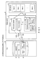
- FIG. 1 is a block diagram illustrating a configuration example of the information processing system 1 according to the first embodiment.
- the information processing system 1 includes a memory system 10 and a host 20 .
- the memory system 10 includes a NAND flash memory (hereinafter referred to as a “NAND memory”) 11 , and a controller 12 .
- NAND memory NAND flash memory
- the NAND memory 11 is a nonvolatile memory which is physically composed of a plurality of chips (for example, four chips), although illustration is omitted here.
- Each NAND memory 11 is composed of a plurality of physical blocks (block 0 to block n) each including a plurality of memory cells which are arranged at intersections between word lines and bit lines.
- data is erased batch-wise in units of this physical block.
- the physical block is an erase unit. Writing and reading are executed in units of a page (word line) in each block.
- the controller 12 controls the entire operations of the SSD 10 .
- the controller 12 controls access to the NAND memory 11 (write, read, erase) and a background process BG which is involved in a preceding process.
- the controller 12 includes a process scheduler 121 , a background processor 122 , a requested write size 123 , a size of a free area 124 , and a data access controller 125 .
- the process scheduler 121 transmits a control signal IS to the background processor 122 so as to execute a predetermined background process, based on an extended command eCOM (second request) which is issued from the host 20 , and schedules the background process. In addition, based on the received extended command eCOM, the process scheduler 121 returns an extended status signal ReS, which indicates the state of the self (SSD) 10 , to the host 20 .
- eCOM second request
- the background processor 122 executes the preceding background process BG for the NAND memory 11 .
- the background process BG refers to a process which aims at maintaining the performance of the SSD 10 , and is other than a process (write, etc.) responding to a request (first request) from the host 20 .
- Examples of the background process BG include garbage collection, block erase, and patrol read.
- garbage collection is described here by way of example.
- the garbage collection (hereinafter, also referred to as “compaction” in some cases) means to generate free blocks by freeing the area occupied with invalid data among the memory areas in the NAND memory 11 , and to increase a size of a free area in the NAND memory 11 .
- the “patrol read” means to periodically read out data from the NAND memory 11 , in order to detect an accumulation of errors mainly due to data retention, before an error correction becomes impossible.
- the background process BG is not limited to these processes, and may include a refresh process, for instance.
- the “refresh process” means that data is read from a block in which errors have accumulated, subjected to the error correction, and then written as corrected data to the block.
- the requested write size 123 is a size of write requested from the host 20 .
- the size of the free area 124 is a size of the free blocks generated in the NAND memory 11 , which is calculated by multiplying the number of free blocks by the block size, the free blocks being generated by garbage collection which is the background process BG to be described later.
- the data access controller 125 controls data access (write, etc.) to the NAND memory 11 , in accordance with a request (first request: write command COM, etc.) from the host 20 , after the above-described background process BG was executed in precedence.
- the host (host apparatus, information process apparatus) 20 drives the SSD 10 and requests write, read and erase of user data from the memory system 10 .
- the host 20 includes, as software components, an operating system 21 , a device driver 22 , and an application 24 .
- the “erase” refers to an UNMAP(TRIM) and a FORMAT command to erase data in SSD 10 , that erases the data which is no longer necessary for the host 20 .
- the operating system (OS, controller) 21 controls the device driver 22 and application 24 , and controls the entire operations of the host 20 .
- the device driver 22 controls an SSD controller 23 , based on the control of the operating system 21 or application 24 .
- the SSD controller 23 executes predetermined access to the controller 12 in accordance with the control of the device driver 22 .
- the application 24 is software which is executed in accordance with the purpose of a specific work, based on the control of the operating system 21 .
- the SSD controller 23 of the host 20 consciously (intentionally) issues to the SSD 10 an extended command eCOM (second request) which is a different definition from the write and read command COM (first request).
- the second request is not limited to a command form (eCOM), and it should suffice if the second request is some other predetermined extended signal (information, instruction, etc.).
- the controller 12 returns an extended status signal ReS to the host 20 as a response to the above-described received extended command eCOM.
- the extended status signal is not limited to a status signal form (ReS), and it should suffice if the extended status signal is some other predetermined extended signal (information, return signal, response, etc.).
- the host 20 can detect at least the state of the NAND memory 11 , based on the returned extended status signal ReS. As a result, the host 20 can instruct a background process (for example, garbage collection, etc.) in accordance with the detected state of the NAND memory 11 , etc. The details will be described later.
- a background process for example, garbage collection, etc.
- an extended predetermined signal may first be transmitted from the SSD 10 to the host 20 , and then an extended predetermined signal may be transmitted from the host apparatus 20 to the SSD 10 .
- a write prenotification command eCOM is taken as an example of the extended command.
- the write prenotification command eCOM is composed of a write size and a write schedule time as its command frame.
- the write size is 10 GB
- the write schedule time is 60 seconds later from the present time that is issued time of the command eCOM.
- the command frame of the write prenotification command eCOM is not limited to that illustrated in FIG. 2 .
- the write prenotification command eCOM may include, as well as the write prenotification time, hint information which can specify a write start time.
- step S 11 the SSD controller 23 on the host 20 side recognizes a write prenotification, based on an instruction from the device driver 22 .
- step S 12 the SSD controller 23 issues a write prenotification command eCOM, which is an extended command, to the SSD 10 .
- the controller 12 based on the received write prenotification command eCOM, the controller 12 returns to the host apparatus 20 an extended status signal ReS which indicates the state of the free blocks in the NAND memory 11 .
- ReS extended status signal
- step S 21 the SSD controller 23 issues a write command COM to the SSD 10 , based on the status signal ReS.
- the controller 12 on the SSD 10 side executes an operation illustrated in FIG. 5 .
- step S 13 of FIG. 5 upon receiving the write prenotification command eCOM, the process scheduler 121 of the controller 12 transmits a control signal IS to the background processor 122 , so as to execute garbage collection.
- the background processor 122 which received the control signal IS, determines whether the requested write size (the write size: 10 GB) 123 described in the received prenotification command eCOM is more than the limit value of the size of the free area 124 in the NAND memory 11 .
- the “limit value” is a predetermined value used to limit the total size of the free area 124 including the free area generated by the instruction from the host 20 in this embodiment.
- the process scheduler 121 compares the write size 10 GB of the write prenotification command eCOM and the limit value of the size of the free area 124 in the NAND memory 11 . Then, the background processor 122 determines whether the write size 10 GB is more than the limit value of the size of the free area 124 in the NAND memory 11 , and returns a determination result to the process scheduler 121 .
- step S 14 based on the above determination result, if the requested write size 123 exceeds the limit value of the size of the free area 124 in the NAND memory 11 (No in S 13 ), the process scheduler 121 controls the background processor 122 so as to change the requested write size 123 to the limit value of the size of the free area 124 .
- step S 15 based on the above determination result, if the requested write size 123 is less than or equal to the limit value of the size of the free area 124 in the NAND memory 11 (Yes in S 13 ), the process scheduler 121 calculates a generation size in the free area 124 in the NAND memory 11 . Specifically, the controller 12 calculates the generation size by subtracting the present size of the free area 124 from the requested write size 123 .
- the “free area” in the NAND memory 11 refers to an area, in which write can be executed to the NAND memory 11 , without garbage collection (compaction) being carried out.
- step S 16 the process scheduler 121 determines whether a time, which is calculated by subtracting the time necessary for compaction (CMP) from the write time specified in the write prenotification command eCOM, is a present time or later (the time interval is positive or not). Specifically, the process scheduler 121 determines whether a time, which is calculated by subtracting the time necessary for CMP from the write schedule time “60 seconds later” of the write prenotification command eCOM, is a present time or later.
- CMP time necessary for compaction
- the time necessary for compaction can be calculated by adding the time required for compaction of a number of source blocks to generate a number of free blocks corresponding to the generation size.
- the compaction time of each block can be calculated from the valid cluster ratio (valid cluster counter) of the block.
- the “valid/invalid clusters” are clusters written in blocks in the NAND memory 11 , and those which referred to by LUT are valid clusters, whereas those not referred to by LUT are invalid clusters.
- the block (compaction source block) which is a target of compaction, is selected from the blocks with the least valid cluster ratios.
- a plurality of source blocks are equal to each other in valid cluster ratio (valid cluster ratio) R, in the following conditions. More specifically, first, the number of source blocks required is sufficiently less as compared to the number of blocks corresponding to the physical capacity or the overprovisioning capacity. Further, there is a correlation between (the size of) the number of source blocks and the size of the write request from the host.
- FIG. 5A illustrates the case where valid data contained in three source blocks each having a valid cluster ratio R of 1/3 is written in one destination block.
- three free blocks are generated, and one free block is consumed.
- two free blocks can be obtained.
- the valid cluster ratio R of a source block is 1/3, two free blocks can be obtained while writing in one destination block.
- One free block is obtained by executing compaction of the valid data included in 1/(1 ⁇ R) source blocks, having the valid cluster ratio R, to R/(1 ⁇ R) destination blocks.
- R the valid cluster ratio of the source block at the present time.
- the time required for one block compaction write is defined as a coefficient ⁇ .
- the time necessary for compaction to obtain f free blocks is proportional to the compaction write size.
- the time necessary for compaction can be obtained using the coefficient ⁇ in the following equation (I). f *( R /(1 ⁇ R ))* ⁇ (I)
- step S 17 in the case of “True” in step S 16 , the process scheduler 121 sets this time in a timer (not shown) for the next start.
- step S 18 in the case of “False” in step S 16 , the process scheduler 121 determines whether the requested write size 123 is less than or equal to the size of the free area 124 in the NAND memory 11 which was set in step S 15 .
- the reason for this is that, with an elapsed time from step S 15 to S 18 , the size of the free area 124 in the NAND memory 11 may fail to satisfy the requested write size of the host 20 .
- the memory system 10 receives an extra write request, from the host or another host, other than the write request prenotified with the eCOM. In this case, a part of the generated free area 124 may be consumed with the extra write request, resulting in a decrease of the size of the free area 124 .
- plural hosts 20 there may be a case that plural hosts 20 exist.
- step S 18 the background processor 122 , which received an instruction of the process scheduler 121 , determines whether the requested write size 123 is less than or equal to the size of the free area 124 .
- step S 19 if the requested write size 123 is less than the size of the free area 124 (No in S 18 ), the process scheduler 121 controls NAND memory 11 to perform compaction for one block of the NAND memory 11 . Specifically, if the condition in step S 18 is not satisfied (No in S 18 ), the background processor 122 , which received the control signal IS from the process scheduler 121 , further executes, prior to write, garbage collection (compaction) as the background process BG for one block of the NAND memory 11 . Subsequently, the scheduler 121 repeats this step S 19 until satisfying the condition of step S 18 .
- the process scheduler 121 returns to the host 20 an extended status signal ReS.
- the host 20 issues the write command COM illustrated in FIG. 4 to the controller 12 of the SSD 10 , based on the extended status signal ReS which was returned from the SSD 10 .
- controller 12 which received the write command COM, executes a write operation illustrated in FIG. 6 .
- step S 22 the data access controller 125 of the controller 12 determines whether there is a background process BG which is executed precedent to this write.
- step S 23 if there is a background process BG which is executed precedent to the write (Yes in S 22 ), the data access controller 125 temporarily stops the preceding background process BG.
- step S 24 if there is no background process BG which has higher priority than the write (No in S 22 ), the data access controller 125 determines whether there is a background process BG with a priority which can be lowered.
- step S 25 if there is a background process BG with a priority which can be lowered (Yes in S 24 ), the data access controller 125 lowers the priority of the other background process (for example, other garbage collection, block erase, etc.).
- the data access controller 125 lowers the priority of the other background process (for example, other garbage collection, block erase, etc.).
- step S 26 if there is no background process BG with a priority which can be lowered (No in S 24 ), the data access controller 125 writes write data into the NAND memory 11 at address, based on the write command COM.
- the data access controller 125 writes write data into the NAND memory 11 at addresses, and then executes a write termination process illustrated in FIG. 7 .
- step S 31 the data access controller 125 determines whether there is a background process which is temporarily stopped in the preceding execution background processes BG.
- step S 33 if there is a temporarily stopped background process in the preceding execution background processes BG (Yes in S 31 ), the data access controller 125 resumes the preceding execution of this background process.
- step S 32 if there is no temporarily stopped background process in the preceding execution background processes BG (No in S 31 ), the data access controller 125 determines whether there is a background process BG with a lowered priority. If there is no background process BG with a lowered priority (No in S 32 ), the data access controller 125 terminates this operation.
- step S 34 if there is a background process BG with a lowered priority (Yes in S 32 ), the data access controller 125 raises the priority of this background process BG and terminates this operation.
- the write performance can be enhanced, and latency can be reduced.
- comparative example 1 is a memory system in which, unlike the first embodiment, the background process (garbage collection) is not executed in precedence.
- a background process (garbage collection) BGA and BGB for securing a free block needs to be executed concurrently with the write process WA and WB.
- the background process BGA and write process WA are started.
- the background process BGB and write process WB are started.
- all write operations are completed.
- comparative example 1 in the write process WA and WB, the background process BGA and BGB needs to be also executed concurrently. Thus, in comparative example 1, all of the performance of write to the NAND memory cannot be allocated to the write process. As a result, comparative example 1 is disadvantageous in that the write performance decreases and the latency increases.
- the scheduler 121 controls the background processor 122 by the control signal IS so as to execute a predetermined background process, based on the extended command eCOM (second request) which is issued from the host 20 .
- the background processor 122 executes the background process BG for the NAND memory 11 preceding the access (write, etc.) ( FIG. 5 , etc.).
- the background processor 122 starts the background process (garbage collection) BGA and BGB, prior to write.
- the write process WA and WB can be started.
- the write performance can be enhanced. Furthermore, in a typical case, the latency can advantageously be reduced by time T 0 , compared to comparative example 1.
- the ratio between write and compaction (garbage collection) according to comparative example 1 is, for example, about 1:1.
- the ratio of compaction write can greatly be decreased, compared to the ratio of write, and, ideally, the ratio of compaction write can be reduced to substantially zero.
- the ratio between write and compaction can be set at about 1:0. In this manner, in the first embodiment, the ratio of write can be improved.
- FIG. 11A to FIG. 11C are views illustrating the relationship between blocks BK and valid cluster ratios, FIG. 11A to FIG. 11C showing valid cluster distributions over physical blocks in an initial state, a first state and a second state, respectively. It should be noted that, in FIG. 11A to FIG. 11C , the size of the hatched areas which correspond to the user capacity of the SSD 10 are equal to each other.
- garbage collection is executed for a target of a block (compaction source block) CBK having a least valid cluster ratio.
- a target of a block (compaction source block) CBK having a least valid cluster ratio.
- compaction is executed for the 5th block as a target.
- compaction is executed for the 7th block and the 10th block as targets.
- comparative example 2 is a memory system which is a drive side and greedily executes preceding compaction.
- the memory system according to comparative example 2 needs to execute a large amount of garbage collection (compaction).
- Point a2) A large amount of compaction has to be executed until reaching the initial state of FIG. 11A from the second state of FIG. 11C .
- the garbage collection process is precedently executed. According to this, the memory system 10 generates the size of the free area 124 when needed in accordance with the required write size.
- the garbage collection process BG prior to write, the garbage collection process BG is precedently executed.
- the write and garbage collection process BG can be executed in a temporally distributed manner.
- the first embodiment is advantageous in that, since these two operations are processed in a temporally distributed manner, the power consumption involved in the process can be distributed, and the peak power consumption can be reduced.
- the method of maximization of peak performance is, in comparative example 2, greedy garbage collection at the discretion of the SSD (drive) itself.
- the first embodiment is different with respect to the preceding garbage collection on the instruction (eCOM) of the host 20 .
- the peak performance is high in each of the comparative example 2 and the first embodiment.
- the preceding compaction amount is excessively large in comparative example 2
- the amount that is a total amount of the generated free blocks necessary for the peak performance based on the host instruction (eCOM) can be obtained in the first embodiment.
- the WAF in comparative example 2 is larger than that in the first embodiment.
- the advantageous effects as described above are not limited to the garbage collection (compaction). Specifically, needless to say, the same advantageous effects as in the above (1) to (4) can be obtained with respect to the other background processes such as block erase and patrol read.
- the second embodiment relates to an example in which the host 20 requests, from the SSD 10 A, switching On/Off of the preceding background process.
- the description below a detailed description of the configurations and operations, which overlap those of the first embodiment, is omitted.
- the second embodiment differs from the first embodiment in that the information processing system 1 A according to the second embodiment does not include the process scheduler 121 , and the extended command eCOM 1 , eCOM 2 is transmitted from the host 20 to the background processor 122 .
- the host 20 transmits the extended command eCOM 1 to the background processor 122 , thereby controlling On (execution) or Off (non-execution) of preceding execution of the background process. Further, the host 20 transmits the extended command eCOM 2 to the background processor 122 , thereby requesting inquiry of the free-area size in the NAND memory 11 , and checking the status of the free area.
- the background processor 122 which received the extended command eCOM 1 , eCOM 2 , returns to the host 20 an extended status signal ReS based on this extended command. For example, the background processor 122 , which received the extended command eCOM 2 , notifies the host 20 of the size of the free area in the NAND memory 11 as the content of the extended status signal ReS based on the command eCOM 2 . The details of these will be described later.
- the extended command eCOM 1 is composed of a control flag of On/Off of preceding execution, and a requested write size. For example, when the preceding execution of the background process is requested to be On, the control flag of the extended command eCOM 1 is set. And when the preceding execution of the background process is requested to be Off, the control flag of the extended command eCOM 1 is set in a “0” state.
- a parameter is not particularly set for the extended command eCOM 2 according to the second embodiment.
- the extended command eCOM 2 is composed such that the extended command eCOM 2 has a different definition from other write command COM, etc., to inquire the size of the free area in the NAND memory 11 .
- the “free area” in the NAND memory 11 refers to an area, which enables writing to the NAND memory 11 without executing garbage collection (compaction).
- the extended status signal ReS according to the second embodiment is composed of a size of the free area, which is calculated from the number of free blocks, as a return signal of the extended command eCOM 2 .
- the content of the size of the free area of the extended status signal ReS according to the second embodiment is described as 5 GB.
- step S 41 the SSD controller 23 of the host 20 recognizes write prenotification based on an instruction of the device driver 22 .
- step S 41 the SSD controller 23 issues an extended command eCOM 1 of preceding execution On to the background processor 122 .
- the SSD controller 23 issues an extended command eCOM 1 with the control flag of the “1” state to the background processor 122 , so as to execute preceding execution of the background process.
- the background processor 122 which received the extended command eCOM 1 , first starts the preceding execution of the background process, since the control flag of the command eCOM 1 is in the “1” state.
- step S 43 the background processor 122 determines whether the requested write size described in the received command eCOM 1 is less than or equal to the limit value of the size of the free area 124 in the NAND memory 11 .
- the background processor 122 compares the write size 10 GB of the command eCOM 1 and the limit value of the size of the free area 124 in the NAND memory 11 . Then, the background processor 122 determines whether the write size 10 GB is less than or equal to the limit value of the size of the free area 124 in the NAND memory 11 .
- step S 44 if the requested write size 123 is greater than the limit value of the size of the free area 124 in the NAND memory 11 (No in S 43 ), the background processor 122 changes the requested write size to the limit value of the size of the free area 124 .
- step S 45 if the requested write size is less than or equal to the limit value of the size of the free area 124 in the NAND memory 11 (Yes in S 43 ), the background processor 122 determines whether the requested write size of the command eCOM 1 is less than or equal to the size of the free area 124 in the NAND memory 11 which was set in step S 43 . This is because with an elapsed time, the size of the free area in the NAND memory 11 may fail to satisfy the requested write size of the host 20 . To be more specific, there is a case where the memory system 10 A receives an extra write request, from the host or another host, other than the write request pre-notified with the eCOM. In this case, a part of the generated free blocks may be consumed with the extra write request, resulting in a decrease of the number of free blocks.
- step S 46 if the requested write size is larger than the size of the free area 124 (No in S 45 ), the background processor 122 controls to perform compaction of one block of the NAND memory 11 . Specifically, in this case, the background processor 122 executes, prior to write, garbage collection (compaction) in advance as the background process BG for one block of the NAND memory 11 . Subsequently, the background processor 122 repeats this step S 46 until satisfying the condition of step S 45 .
- step S 45 the background processor 122 returns to the host 20 an extended status signal ReS which is indicative of the size of the free area (for example, 5 GB) which is calculated from the number of free blocks.
- step S 51 based on an instruction of the device driver 22 , the SSD controller 23 of the host 20 issues an extended command eCOM 2 to the background processor 122 of the SSD 10 A, as an inquiry of the generation status of the free blocks in the SSD 10 A.
- step S 52 based on an extended status signal ReS (to be described later in detail with reference to FIG. 16B ) which was returned from the background processor 122 , the SSD controller 23 determines whether the size of the free area in the SSD 10 A (size 5 GB of free area of ReS) has reached an instructed value.
- ReS extended status signal
- step S 53 if the size of the free area in the SSD 10 A has not reached the instructed value (No in S 52 ), the SSD controller 23 sets a timer (not shown) for the next time.
- step S 54 if the size of the free area in the SSD 10 has reached the instructed value (Yes in S 52 ), the SSD controller 23 issues a command eCOM 1 by which the preceding execution of the background process in the Off state. Specifically, the SSD controller 23 issues to the background processor 122 the extended command eCOM 1 with the flag in the “0” state, so as not to carry out the preceding execution of the background process.
- the background processor 122 which received the extended command eCOM 2 as the inquiry of the generation status of the free blocks in step S 51 of FIG. 16A , acquires the number of free blocks. Specifically, the background processor 122 acquires the number of free blocks which can be used up for write to the NAND memory 11 .
- step S 56 the background processor 122 calculates the size of the free area. Specifically, the background processor 122 multiplies the number of free blocks, which was acquired in step S 55 , by the block size, and calculates the size of the free area.
- step S 57 the background processor 122 transmits to the host 20 a status signal ReS describing the size (for example, 5 GB) of the free area calculated in step S 56 .
- step S 58 of FIG. 16C the background processor 122 , which received the extended command eCOM 1 in step S 54 of FIG. 16A , determines whether there is a background process BG which is being executed in precedence. If the condition of step S 58 is not satisfied (No in S 58 ), the background processor 122 terminates the operation of turning preceding background process Off.
- step S 59 if the condition of step S 58 is satisfied (Yes in S 58 ), the background processor 122 stops the background process (for example, garbage collection process) BG which is being executed.
- the background processor 122 stops the background process (for example, garbage collection process) BG which is being executed.
- step S 61 the SSD controller 23 determines, in step S 61 , whether the preceding execution of the background process BG is in the On state or not. If this condition of step S 61 is not satisfied (No in S 61 ), the process goes to step S 63 .
- step S 62 in order to set the preceding execution of the background process BG into the Off state, the SSD controller 23 issues to the SSD 10 A an extended command eCOM 1 with the control flag indicating the “0” state.
- step S 63 the SSD controller 23 receives a status signal ReS from the background processor 122 , and issues a write command COM to the SSD 10 A.
- the write operation executed by the data access controller 125 after receiving the write command COM are substantially the same as those in the above-described first embodiment. Thus, a detailed description thereof is omitted.
- the host 20 transmits the extended command eCOM 1 to the SSD 10 A, and requests switching On/Off of the preceding background process ( FIG. 14A , FIG. 15A ).
- the background processor 122 of the SSD 10 A which received this command eCOM 1 , executes garbage collection as the background process, prior to the write operation ( FIG. 15B ).
- the background processor 122 continues to generate free blocks until the size of the free area 124 reaches the requested write size 123 ( FIG. 15B ).
- the host 20 sets the preceding execution of the background process of the SSD 10 in the Off state ( FIG. 16A to FIG. 16C , FIG. 17 ).
- the host 20 issues an inquiry to the SSD 10 A by sending the extended command eCOM 2 , and monitors the generation status of the free blocks in the SSD 10 A (S 51 to S 52 of FIG. 16A , etc.).
- the above control which is executed by the information processing system 1 A of the second embodiment, is illustrated as shown in FIG. 18 .
- the host 20 transmits the command eCOM 2 to the SSD 10 A, and executes check 1 of the generation status of the free blocks in the SSD 10 A.
- the host 20 transmits the command eCOM 1 to the SSD 10 A, and requests On of preceding execution of the garbage collection as the background process.
- the host 20 similarly transmits the command eCOM 2 to the SSD 10 A, and executes check 2 and check 3 of the generation status of the free blocks in the SSD 10 A.
- the host 20 transmits the command eCOM 1 to the SSD 10 A, based on the check result of the check 3, and requests Off of preceding execution of the garbage collection as the background process.
- the selectivity of the information processing system 1 A can be broad, without the provision of the process scheduler 121 .
- the second embodiment can be applied.
- Modification 1 is an example of a variation of the second embodiment.
- Modification 1 differs from the second embodiment in that the information processing system 1 B according to Modification 1 does not include the requested write size 123 .
- step S 71 the SSD controller 23 of the host 20 issues an extended command eCOM 2 to the background processor 122 , and inquires about the generation status of the free blocks generated by the background process BG executed in precedence.
- the background processor 122 which received the inquiry, returns the size of the free area 124 to the SSD controller 23 by an extended status signal ReS.
- step S 72 the SSD controller 23 determines whether the requested write size, which the host 20 requires to execute to the memory system 1 , is larger than the size of the free area 124 . To be more specific, based on the size of the free area 124 which is described in the returned status signal ReS, the SSD controller 23 determines whether the write size required by the host 20 is larger than the size of the free area 124 . If the condition of step S 72 is not satisfied (No in S 72 ), the process goes to step S 74 .
- step S 73 if the requested write size, which the host 20 requires to execute to the memory system 1 B, is larger than the size of the free area 124 (Yes in S 72 ), the SSD controller 23 makes the write size regulated to the size of the free area 124 .
- step S 74 based on the set size, the SSD controller 23 issues a write command COM to the data access controller 125 .
- the size of the free area 124 which was generated by the background process BG that was executed in precedence, is larger than the write size required by the host 20 .
- the SSD controller 23 issues the write command COM so as to execute write, based on the set size (the write size).
- the SSD controller 23 issues the write command COM so as that the requested write size is equalized to the size of the free area 124 .
- the host 20 issues the command eCOM 2 to the SSD 10 B and inquires about the generation status of the free blocks 124 in the SSD 10 B (S 71 in FIG. 20 ). Then the host 20 writes the data of the size of the free area, based on the inquiry (S 72 to S 74 in FIG. 20 ).
- the host 20 executes write for an acceptable write size in accordance with the size of the free area 124 (S 73 in FIG. 20 ).
- the host 20 can write for up to the acceptable write size in accordance with the size of the free area in the NAND memory 11 .
- control which is executed by the information processing system 1 B of Modification 1, is illustrated as shown in FIG. 21 .
- the host 20 issues the command eCOM 2 to the SSD 10 B, and executes check 1 of the generation status of the free blocks 124 in the SSD 10 B (S 71 in FIG. 20 ).
- the host 20 transmits the command eCOM 1 to the SSD 10 B, and requests On of preceding execution of the garbage collection as the background process.
- the host 20 similarly issues the command eCOM 2 to the SSD 10 B, and executes check 2 of the generation status of the free blocks 124 in the SSD 10 B.
- the host 20 issues the write command COM to the SSD 10 B, based on the size 1 GB described in the extended status signal ReS, which is the check result of the check 2, and causes the SSD 10 B to execute write of the size 1 GB.
- Modification 1 the selectivity of the information processing system 1 can be broad, without the provision of the process scheduler 121 and the requested write size 123 .
- Modification 1 can be applied.
- FIG. 22 is a block diagram illustrating an example of the detailed configuration of an information processing system 1 C according to the third embodiment.
- the process scheduler 121 and background processor 122 according to the above-described first and second embodiments and Modification 1 correspond to, for example, a CPU 43 B, etc.
- the data access controller 125 according to the above-described first and second embodiments and Modification 1 corresponds to, for example, a host interface 41 , etc.
- the requested write size 123 and the size of the free area 124 may be located in a volatile memory and used.
- the controller 12 C includes a front end 12 F and a back end 12 B.
- the front end (host communication unit) 12 F includes the host interface 41 , a host interface controller 42 , an encryption/decryption unit (Advanced Encryption Standard [AES]) 44 , and the CPU 43 F.
- AES Advanced Encryption Standard
- the host interface 41 communicates with the information processing apparatus 20 for communication of requests (write command, read command, erase command (UNMAP(TRIM) command), etc.), logical addresses LBA, and data.
- the host controller (controller) 42 controls the communication of the host interface 41 , based on the control of the CPU 43 F.
- the encryption/decryption unit (Advanced Encryption Standard [AES]) 44 encrypts, in a write operation, write data (plain text) which is sent from the host interface controller 42 .
- the encryption/decryption unit 44 decrypts, in a read operation, encrypted read data which is sent from a read buffer RB of the back end 12 B. It should be noted that, where necessary, write data and read data can be transmitted without the intervention of the encryption/decryption unit 44 .
- the CPU 43 F controls the respective components 41 , 42 and 44 of the front end 12 F, and controls the entire operations of the front end 12 F.
- the back end (memory communication unit) 12 B includes a write buffer WB, the read buffer RB, an LUT unit 45 , a DDRC 46 , a DRAM 47 , a DMAC 48 , an ECC 49 , a randomizer RZ, a NANDC 50 , and a CPU 43 B.
- the write buffer (write data transfer unit) WB temporarily stores write data WD which is transmitted from the host 20 . Specifically, the write buffer WB temporarily stores data until the size of the write data WD reaches a predetermined size that is suited to the NAND memory 11 .
- the read buffer (read data transfer unit) RB temporarily stores read data RD which was read out from the NAND memory 11 . Specifically, in the read buffer RB, the read data RD is rearranged in an order suited to the host 20 (an order of logical addresses LBA which is designated by the host 20 ).
- the look-up table (LUT) 45 is a conversion table to convert the logical address LBA to a corresponding physical address PBA.
- the DDRC 46 controls a double data rate (DDR) in the DRAM 47 .
- DDR double data rate
- the dynamic random access memory (DRAM) 47 is, for example, a volatile memory which stores the LUT 45 .
- the direct memory access controller (DMAC) 48 transfers write data WD and read data RD via an internal bus IB.
- the controller 12 may include two or more DMACs 48 .
- the DMAC 48 is set at various positions in the controller 12 , where necessary.
- the error correction unit (ECU) 49 adds an error correction code (ECC) to the write data WD which is sent from the write buffer WB.
- ECC error correction code
- the ECC 49 corrects, where necessary, the read data RD which was read out from the NAND memory 11 , by using the added ECC, when the ECC 49 sends the read data RD to the read buffer RB.
- the randomizer (or scrambler) RZ is configured to equalize the frequency of being programmed as 1 and that as 0 for each cell (wear leveling for each cell) and to suppress unevenness in the numbers of 1 and 0 within a page (reduction of interference between cells or between pages, and equalization). In this manner, the number of times of write can be leveled, and the life of the NAND memory 11 can be increased. Therefore, the reliability of the NAND memory 11 can be enhanced.
- the NAND controller (NANDC) 50 accesses the NAND memory 11 in parallel by using a plurality of channels (in this example, four channels CH0 to CH3), in order to meet a predetermined speed requirement.
- a plurality of channels in this example, four channels CH0 to CH3
- the CPU 43 B controls the above-described respective structural components (45 to 50, RZ) of the back end 12 B, and controls the entire operations of the back end 12 B.
- controller 12 illustrated in FIG. 22 is merely an example, and is not limited to the illustrated configuration.
- FIG. 23 is a perspective view illustrating a storage system 100 according to the third embodiment.
- the storage system 100 includes a plurality of memory systems 10 as SSDs.
- the external appearance of the memory system 10 is, for example, a relatively small module, and the outer-shape dimensions are, for instance, about 120 mm ⁇ 130 mm. It should be noted that the size and dimensions of the memory system 10 are not limited to these, and proper changes to various sizes are possible.
- the memory system 10 can be used by being mounted in the host 20 that is an information processing apparatus such as a server, in a data center or a cloud computing system which is operated in a company (enterprise).
- the memory system 10 may be an Enterprise SSD (eSSD).
- the host 20 includes a plurality of connectors (for example, slots) 30 which open upward, for example.
- Each connector 30 is, for instance, a SAS (Serial Attached SCSI) connector. According to this SAS connector, the host 20 and each memory system 10 can execute high speed communication by 6 Gbps dual ports. It should be noted that each connector 30 is not limited to this, and may be, for instance, a PCI Express (PCIe).
- PCIe PCI Express
- the plural memory systems 10 are attached to the connectors 30 of the host 20 , respectively, and are juxtaposed and supported in upright attitudes in a substantially vertical direction. According to this configuration, the plural memory systems 10 can be mounted in a compact size, and the size of the memory system 10 can be reduced. Furthermore, the shape of each memory system 10 of the third embodiment is a 2.5 type SFF (Small Form Factor). By this shape, the memory system 10 can have a compatible shape with an Enterprise HDD (eHDD), and system compatibility with the eHDD can be realized.
- eHDD Enterprise HDD
- the memory system 10 is not limited to the use for enterprises.
- the memory system 10 is applicable as a storage medium of a consumer electronic device such as a notebook computer or a tablet computer.
Landscapes
- Engineering & Computer Science (AREA)
- Theoretical Computer Science (AREA)
- Physics & Mathematics (AREA)
- General Engineering & Computer Science (AREA)
- General Physics & Mathematics (AREA)
- Human Computer Interaction (AREA)
- Memory System (AREA)
- Techniques For Improving Reliability Of Storages (AREA)
Abstract
Description
f*(R/(1−R))*α (I)
Claims (18)
Priority Applications (2)
| Application Number | Priority Date | Filing Date | Title |
|---|---|---|---|
| US15/819,474 US10095410B2 (en) | 2014-12-24 | 2017-11-21 | Memory system with garbage collection |
| US16/123,465 US10402097B2 (en) | 2014-12-24 | 2018-09-06 | Memory system and information processing system utilizing space information |
Applications Claiming Priority (2)
| Application Number | Priority Date | Filing Date | Title |
|---|---|---|---|
| JP2014259951A JP2016122227A (en) | 2014-12-24 | 2014-12-24 | Memory system and information processing system |
| JP2014-259951 | 2014-12-24 |
Related Child Applications (1)
| Application Number | Title | Priority Date | Filing Date |
|---|---|---|---|
| US15/819,474 Continuation US10095410B2 (en) | 2014-12-24 | 2017-11-21 | Memory system with garbage collection |
Publications (2)
| Publication Number | Publication Date |
|---|---|
| US20160188220A1 US20160188220A1 (en) | 2016-06-30 |
| US9857984B2 true US9857984B2 (en) | 2018-01-02 |
Family
ID=56164200
Family Applications (3)
| Application Number | Title | Priority Date | Filing Date |
|---|---|---|---|
| US14/757,559 Active US9857984B2 (en) | 2014-12-24 | 2015-12-24 | Memory system with garbage collection |
| US15/819,474 Active US10095410B2 (en) | 2014-12-24 | 2017-11-21 | Memory system with garbage collection |
| US16/123,465 Active US10402097B2 (en) | 2014-12-24 | 2018-09-06 | Memory system and information processing system utilizing space information |
Family Applications After (2)
| Application Number | Title | Priority Date | Filing Date |
|---|---|---|---|
| US15/819,474 Active US10095410B2 (en) | 2014-12-24 | 2017-11-21 | Memory system with garbage collection |
| US16/123,465 Active US10402097B2 (en) | 2014-12-24 | 2018-09-06 | Memory system and information processing system utilizing space information |
Country Status (2)
| Country | Link |
|---|---|
| US (3) | US9857984B2 (en) |
| JP (1) | JP2016122227A (en) |
Families Citing this family (16)
| Publication number | Priority date | Publication date | Assignee | Title |
|---|---|---|---|---|
| US10877669B1 (en) * | 2011-06-30 | 2020-12-29 | Amazon Technologies, Inc. | System and method for providing a committed throughput level in a data store |
| JP2016122227A (en) | 2014-12-24 | 2016-07-07 | 株式会社東芝 | Memory system and information processing system |
| US9696935B2 (en) | 2015-04-24 | 2017-07-04 | Kabushiki Kaisha Toshiba | Storage device that secures a block for a stream or namespace and system having the storage device |
| US10665305B2 (en) * | 2015-09-09 | 2020-05-26 | Toshiba Memory Corporation | Host device connectable to memory device performing patrol read and memory device performing patrol read |
| JP6524039B2 (en) * | 2016-09-23 | 2019-06-05 | 東芝メモリ株式会社 | Memory system and control method |
| KR20180047402A (en) * | 2016-10-31 | 2018-05-10 | 삼성전자주식회사 | Storage device managing multi-namespaces and Method of operating the storage device |
| US10379943B2 (en) * | 2016-12-06 | 2019-08-13 | International Business Machines Corporation | Management of foreground and background processes in a storage controller |
| US10971241B2 (en) | 2017-01-30 | 2021-04-06 | Toshiba Memory Corporation | Performance based method and system for patrolling read disturb errors in a memory unit |
| KR102447602B1 (en) | 2017-10-25 | 2022-09-26 | 삼성전자주식회사 | Memory device and Dynamic garbage collection Method thereof |
| US10331555B1 (en) * | 2018-03-06 | 2019-06-25 | Western Digital Technologies, Inc. | Dynamic memory compaction |
| KR20190120966A (en) * | 2018-04-17 | 2019-10-25 | 에스케이하이닉스 주식회사 | Storage device and operating method thereof |
| JP2020003838A (en) | 2018-06-25 | 2020-01-09 | キオクシア株式会社 | Memory system |
| US11074007B2 (en) | 2018-08-08 | 2021-07-27 | Micron Technology, Inc. | Optimize information requests to a memory system |
| US10969994B2 (en) * | 2018-08-08 | 2021-04-06 | Micron Technology, Inc. | Throttle response signals from a memory system |
| KR102653659B1 (en) * | 2019-07-05 | 2024-04-03 | 에스케이하이닉스 주식회사 | Memory system, memory controller, and operating method |
| JP7321851B2 (en) | 2019-09-09 | 2023-08-07 | キオクシア株式会社 | Memory system and garbage collection control method |
Citations (9)
| Publication number | Priority date | Publication date | Assignee | Title |
|---|---|---|---|---|
| US20080082728A1 (en) * | 2006-09-28 | 2008-04-03 | Shai Traister | Memory systems for phased garbage collection using phased garbage collection block or scratch pad block as a buffer |
| US20080201336A1 (en) * | 2007-02-20 | 2008-08-21 | Junichi Yamato | Distributed data storage system, data distribution method, and apparatus and program to be used for the same |
| US20130246688A1 (en) | 2012-03-15 | 2013-09-19 | Kabushiki Kaisha Toshiba | Semiconductor memory device and computer program product |
| US20130290619A1 (en) * | 2012-04-30 | 2013-10-31 | Netapp, Inc. | Apparatus and Method for Sequential Operation on a Random Access Device |
| US8683148B2 (en) * | 2010-06-30 | 2014-03-25 | Sandisk Il Ltd. | Status indication when a maintenance operation is to be performed at a memory device |
| US20150347025A1 (en) * | 2014-05-27 | 2015-12-03 | Kabushiki Kaisha Toshiba | Host-controlled garbage collection |
| US20160041762A1 (en) * | 2014-08-08 | 2016-02-11 | Kabushiki Kaisha Toshiba | Memory system, host device and information processing system |
| US20160188220A1 (en) * | 2014-12-24 | 2016-06-30 | Kabushiki Kaisha Toshiba | Memory system and information processing system |
| US20160291872A1 (en) * | 2015-04-03 | 2016-10-06 | Kabushiki Kaisha Toshiba | Storage device writing data on the basis of stream |
Family Cites Families (9)
| Publication number | Priority date | Publication date | Assignee | Title |
|---|---|---|---|---|
| US8429352B2 (en) * | 2007-06-08 | 2013-04-23 | Sandisk Technologies Inc. | Method and system for memory block flushing |
| WO2010094332A1 (en) * | 2009-02-19 | 2010-08-26 | Ametek Denmark A/S | A temperature calibration device, a calibrator block, and a method for calibrating a temperature probe |
| JP5731708B2 (en) * | 2011-04-06 | 2015-06-10 | ダウ グローバル テクノロジーズ エルエルシー | Novel polysaccharide derivatives and dosage forms |
| US20150034702A1 (en) * | 2013-08-01 | 2015-02-05 | Semigear Inc | Apparatus & method for treating substrate |
| KR102164617B1 (en) * | 2014-03-24 | 2020-10-12 | 삼성전자주식회사 | Method for operating a data storage device and method for operating a system including the same |
| CN105630638B (en) * | 2014-10-31 | 2018-01-12 | 国际商业机器公司 | For the apparatus and method for disk array distribution caching |
| CN108139968B (en) * | 2015-10-19 | 2020-12-04 | 华为技术有限公司 | Method and equipment for determining quantity of threads of garbage collector and managing activities |
| US9946483B2 (en) * | 2015-12-03 | 2018-04-17 | Sandisk Technologies Llc | Efficiently managing unmapped blocks to extend life of solid state drive with low over-provisioning |
| TWI619018B (en) * | 2016-11-10 | 2018-03-21 | 慧榮科技股份有限公司 | Garbage collection method for data storage device |
-
2014
- 2014-12-24 JP JP2014259951A patent/JP2016122227A/en active Pending
-
2015
- 2015-12-24 US US14/757,559 patent/US9857984B2/en active Active
-
2017
- 2017-11-21 US US15/819,474 patent/US10095410B2/en active Active
-
2018
- 2018-09-06 US US16/123,465 patent/US10402097B2/en active Active
Patent Citations (9)
| Publication number | Priority date | Publication date | Assignee | Title |
|---|---|---|---|---|
| US20080082728A1 (en) * | 2006-09-28 | 2008-04-03 | Shai Traister | Memory systems for phased garbage collection using phased garbage collection block or scratch pad block as a buffer |
| US20080201336A1 (en) * | 2007-02-20 | 2008-08-21 | Junichi Yamato | Distributed data storage system, data distribution method, and apparatus and program to be used for the same |
| US8683148B2 (en) * | 2010-06-30 | 2014-03-25 | Sandisk Il Ltd. | Status indication when a maintenance operation is to be performed at a memory device |
| US20130246688A1 (en) | 2012-03-15 | 2013-09-19 | Kabushiki Kaisha Toshiba | Semiconductor memory device and computer program product |
| US20130290619A1 (en) * | 2012-04-30 | 2013-10-31 | Netapp, Inc. | Apparatus and Method for Sequential Operation on a Random Access Device |
| US20150347025A1 (en) * | 2014-05-27 | 2015-12-03 | Kabushiki Kaisha Toshiba | Host-controlled garbage collection |
| US20160041762A1 (en) * | 2014-08-08 | 2016-02-11 | Kabushiki Kaisha Toshiba | Memory system, host device and information processing system |
| US20160188220A1 (en) * | 2014-12-24 | 2016-06-30 | Kabushiki Kaisha Toshiba | Memory system and information processing system |
| US20160291872A1 (en) * | 2015-04-03 | 2016-10-06 | Kabushiki Kaisha Toshiba | Storage device writing data on the basis of stream |
Also Published As
| Publication number | Publication date |
|---|---|
| US20190018596A1 (en) | 2019-01-17 |
| US10095410B2 (en) | 2018-10-09 |
| US20160188220A1 (en) | 2016-06-30 |
| JP2016122227A (en) | 2016-07-07 |
| US10402097B2 (en) | 2019-09-03 |
| US20180088828A1 (en) | 2018-03-29 |
Similar Documents
| Publication | Publication Date | Title |
|---|---|---|
| US10402097B2 (en) | Memory system and information processing system utilizing space information | |
| US10824553B2 (en) | Memory device that controls timing of receiving write data from a host | |
| US9836224B2 (en) | Storage controller, storage system and method of operating storage controller | |
| US8332579B2 (en) | Data storage apparatus and method of writing data | |
| US20160210060A1 (en) | Dynamic resource allocation within storage devices | |
| KR102098697B1 (en) | Non-volatile memory system, system having the same and method for performing adaptive user storage region adjustment in the same | |
| US9846541B2 (en) | Memory system for controlling perforamce by adjusting amount of parallel operations | |
| US10599349B2 (en) | Method and apparatus of dynamic parallelism for controlling power consumption of SSDs | |
| US20140101370A1 (en) | Apparatus and method for low power low latency high capacity storage class memory | |
| US20120166911A1 (en) | Data storage apparatus and apparatus and method for controlling nonvolatile memories | |
| US9436267B2 (en) | Data storage device | |
| US8589768B2 (en) | Memory system having multiple channels and write control method including determination of error correction channel in memory system | |
| US20210216239A1 (en) | Host controlled garbage collection in a solid state drive | |
| KR102615227B1 (en) | Memory system and operating method thereof | |
| US20200042238A1 (en) | Data storage device, method of operating the same, and storage system having the same | |
| US11847327B2 (en) | Centralized power management in memory devices | |
| KR20200114052A (en) | Controller, memory system and operating method thereof | |
| KR102381233B1 (en) | Data storage device and operating method thereof | |
| US11775188B2 (en) | Communications to reclaim storage space occupied by proof of space plots in solid state drives | |
| TWI786288B (en) | Storage device, control method therefor and storage medium | |
| US20230244394A1 (en) | Gradually Reclaim Storage Space Occupied by a Proof of Space Plot in a Solid State Drive | |
| KR20150041873A (en) | Data processing system | |
| US20120159024A1 (en) | Semiconductor apparatus | |
| KR20190102998A (en) | Data storage device and operating method thereof | |
| US20240094911A1 (en) | Dynamic And Shared CMB And HMB Allocation |
Legal Events
| Date | Code | Title | Description |
|---|---|---|---|
| AS | Assignment |
Owner name: KABUSHIKI KAISHA TOSHIBA, JAPAN Free format text: ASSIGNMENT OF ASSIGNORS INTEREST;ASSIGNORS:NEMOTO, HIROYUKI;KITSUNAI, KAZUYA;KOJIMA, YOSHIHISA;AND OTHERS;REEL/FRAME:037625/0143 Effective date: 20160107 |
|
| AS | Assignment |
Owner name: TOSHIBA MEMORY CORPORATION, JAPAN Free format text: ASSIGNMENT OF ASSIGNORS INTEREST;ASSIGNOR:KABUSHIKI KAISHA TOSHIBA;REEL/FRAME:043529/0709 Effective date: 20170628 |
|
| STCF | Information on status: patent grant |
Free format text: PATENTED CASE |
|
| AS | Assignment |
Owner name: K.K. PANGEA, JAPAN Free format text: MERGER;ASSIGNOR:TOSHIBA MEMORY CORPORATION;REEL/FRAME:055659/0471 Effective date: 20180801 Owner name: KIOXIA CORPORATION, JAPAN Free format text: CHANGE OF NAME AND ADDRESS;ASSIGNOR:TOSHIBA MEMORY CORPORATION;REEL/FRAME:055669/0001 Effective date: 20191001 Owner name: TOSHIBA MEMORY CORPORATION, JAPAN Free format text: CHANGE OF NAME AND ADDRESS;ASSIGNOR:K.K. PANGEA;REEL/FRAME:055669/0401 Effective date: 20180801 |
|
| MAFP | Maintenance fee payment |
Free format text: PAYMENT OF MAINTENANCE FEE, 4TH YEAR, LARGE ENTITY (ORIGINAL EVENT CODE: M1551); ENTITY STATUS OF PATENT OWNER: LARGE ENTITY Year of fee payment: 4 |