US9651663B2 - Distance measurement apparatus - Google Patents
Distance measurement apparatus Download PDFInfo
- Publication number
- US9651663B2 US9651663B2 US15/151,586 US201615151586A US9651663B2 US 9651663 B2 US9651663 B2 US 9651663B2 US 201615151586 A US201615151586 A US 201615151586A US 9651663 B2 US9651663 B2 US 9651663B2
- Authority
- US
- United States
- Prior art keywords
- laser light
- output
- laser
- threshold value
- photodiode
- Prior art date
- Legal status (The legal status is an assumption and is not a legal conclusion. Google has not performed a legal analysis and makes no representation as to the accuracy of the status listed.)
- Active
Links
Images


Classifications
-
- G—PHYSICS
- G01—MEASURING; TESTING
- G01S—RADIO DIRECTION-FINDING; RADIO NAVIGATION; DETERMINING DISTANCE OR VELOCITY BY USE OF RADIO WAVES; LOCATING OR PRESENCE-DETECTING BY USE OF THE REFLECTION OR RERADIATION OF RADIO WAVES; ANALOGOUS ARRANGEMENTS USING OTHER WAVES
- G01S17/00—Systems using the reflection or reradiation of electromagnetic waves other than radio waves, e.g. lidar systems
- G01S17/02—Systems using the reflection of electromagnetic waves other than radio waves
- G01S17/06—Systems determining position data of a target
- G01S17/46—Indirect determination of position data
- G01S17/48—Active triangulation systems, i.e. using the transmission and reflection of electromagnetic waves other than radio waves
-
- G—PHYSICS
- G01—MEASURING; TESTING
- G01S—RADIO DIRECTION-FINDING; RADIO NAVIGATION; DETERMINING DISTANCE OR VELOCITY BY USE OF RADIO WAVES; LOCATING OR PRESENCE-DETECTING BY USE OF THE REFLECTION OR RERADIATION OF RADIO WAVES; ANALOGOUS ARRANGEMENTS USING OTHER WAVES
- G01S17/00—Systems using the reflection or reradiation of electromagnetic waves other than radio waves, e.g. lidar systems
- G01S17/02—Systems using the reflection of electromagnetic waves other than radio waves
- G01S17/06—Systems determining position data of a target
- G01S17/08—Systems determining position data of a target for measuring distance only
- G01S17/32—Systems determining position data of a target for measuring distance only using transmission of continuous waves, whether amplitude-, frequency-, or phase-modulated, or unmodulated
-
- G01S17/105—
-
- G—PHYSICS
- G01—MEASURING; TESTING
- G01S—RADIO DIRECTION-FINDING; RADIO NAVIGATION; DETERMINING DISTANCE OR VELOCITY BY USE OF RADIO WAVES; LOCATING OR PRESENCE-DETECTING BY USE OF THE REFLECTION OR RERADIATION OF RADIO WAVES; ANALOGOUS ARRANGEMENTS USING OTHER WAVES
- G01S17/00—Systems using the reflection or reradiation of electromagnetic waves other than radio waves, e.g. lidar systems
- G01S17/02—Systems using the reflection of electromagnetic waves other than radio waves
- G01S17/06—Systems determining position data of a target
- G01S17/08—Systems determining position data of a target for measuring distance only
- G01S17/10—Systems determining position data of a target for measuring distance only using transmission of interrupted, pulse-modulated waves
- G01S17/14—Systems determining position data of a target for measuring distance only using transmission of interrupted, pulse-modulated waves wherein a voltage or current pulse is initiated and terminated in accordance with the pulse transmission and echo reception respectively, e.g. using counters
-
- G—PHYSICS
- G01—MEASURING; TESTING
- G01S—RADIO DIRECTION-FINDING; RADIO NAVIGATION; DETERMINING DISTANCE OR VELOCITY BY USE OF RADIO WAVES; LOCATING OR PRESENCE-DETECTING BY USE OF THE REFLECTION OR RERADIATION OF RADIO WAVES; ANALOGOUS ARRANGEMENTS USING OTHER WAVES
- G01S17/00—Systems using the reflection or reradiation of electromagnetic waves other than radio waves, e.g. lidar systems
- G01S17/02—Systems using the reflection of electromagnetic waves other than radio waves
- G01S17/06—Systems determining position data of a target
- G01S17/42—Simultaneous measurement of distance and other co-ordinates
-
- G—PHYSICS
- G01—MEASURING; TESTING
- G01S—RADIO DIRECTION-FINDING; RADIO NAVIGATION; DETERMINING DISTANCE OR VELOCITY BY USE OF RADIO WAVES; LOCATING OR PRESENCE-DETECTING BY USE OF THE REFLECTION OR RERADIATION OF RADIO WAVES; ANALOGOUS ARRANGEMENTS USING OTHER WAVES
- G01S7/00—Details of systems according to groups G01S13/00, G01S15/00, G01S17/00
- G01S7/48—Details of systems according to groups G01S13/00, G01S15/00, G01S17/00 of systems according to group G01S17/00
- G01S7/4808—Evaluating distance, position or velocity data
-
- G—PHYSICS
- G01—MEASURING; TESTING
- G01S—RADIO DIRECTION-FINDING; RADIO NAVIGATION; DETERMINING DISTANCE OR VELOCITY BY USE OF RADIO WAVES; LOCATING OR PRESENCE-DETECTING BY USE OF THE REFLECTION OR RERADIATION OF RADIO WAVES; ANALOGOUS ARRANGEMENTS USING OTHER WAVES
- G01S7/00—Details of systems according to groups G01S13/00, G01S15/00, G01S17/00
- G01S7/48—Details of systems according to groups G01S13/00, G01S15/00, G01S17/00 of systems according to group G01S17/00
- G01S7/481—Constructional features, e.g. arrangements of optical elements
- G01S7/4811—Constructional features, e.g. arrangements of optical elements common to transmitter and receiver
- G01S7/4812—Constructional features, e.g. arrangements of optical elements common to transmitter and receiver transmitted and received beams following a coaxial path
-
- G—PHYSICS
- G01—MEASURING; TESTING
- G01S—RADIO DIRECTION-FINDING; RADIO NAVIGATION; DETERMINING DISTANCE OR VELOCITY BY USE OF RADIO WAVES; LOCATING OR PRESENCE-DETECTING BY USE OF THE REFLECTION OR RERADIATION OF RADIO WAVES; ANALOGOUS ARRANGEMENTS USING OTHER WAVES
- G01S7/00—Details of systems according to groups G01S13/00, G01S15/00, G01S17/00
- G01S7/48—Details of systems according to groups G01S13/00, G01S15/00, G01S17/00 of systems according to group G01S17/00
- G01S7/481—Constructional features, e.g. arrangements of optical elements
- G01S7/4817—Constructional features, e.g. arrangements of optical elements relating to scanning
-
- G—PHYSICS
- G01—MEASURING; TESTING
- G01S—RADIO DIRECTION-FINDING; RADIO NAVIGATION; DETERMINING DISTANCE OR VELOCITY BY USE OF RADIO WAVES; LOCATING OR PRESENCE-DETECTING BY USE OF THE REFLECTION OR RERADIATION OF RADIO WAVES; ANALOGOUS ARRANGEMENTS USING OTHER WAVES
- G01S7/00—Details of systems according to groups G01S13/00, G01S15/00, G01S17/00
- G01S7/48—Details of systems according to groups G01S13/00, G01S15/00, G01S17/00 of systems according to group G01S17/00
- G01S7/483—Details of pulse systems
- G01S7/486—Receivers
-
- G—PHYSICS
- G01—MEASURING; TESTING
- G01S—RADIO DIRECTION-FINDING; RADIO NAVIGATION; DETERMINING DISTANCE OR VELOCITY BY USE OF RADIO WAVES; LOCATING OR PRESENCE-DETECTING BY USE OF THE REFLECTION OR RERADIATION OF RADIO WAVES; ANALOGOUS ARRANGEMENTS USING OTHER WAVES
- G01S7/00—Details of systems according to groups G01S13/00, G01S15/00, G01S17/00
- G01S7/48—Details of systems according to groups G01S13/00, G01S15/00, G01S17/00 of systems according to group G01S17/00
- G01S7/491—Details of non-pulse systems
- G01S7/4912—Receivers
- G01S7/4916—Receivers using self-mixing in the laser cavity
Definitions
- Embodiments described herein relate generally to a distance measurement technology with a fight time measurement method.
- a distance measurement apparatus which can be used for measurement of the three-dimensional shape of a commodity or a component.
- a distance measurement apparatus which is small in size and cheap in cost is required to be capable of measuring at a high speed in a non-contact manner.
- a distance measurement apparatus for example, see Japanese Unexamined Patent Application Publication No. Hei 6-213658 that measures a distance through a triangulation method using laser light and a distance measurement apparatus (for example, see Japanese Unexamined Patent Application Publication No. 2014-102072) that measures a distance through a fight time measurement method using laser light are developed.
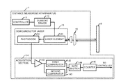
- FIG. 1 is a diagram illustrating a distance measurement apparatus 7 that measures a distance through the triangulation method.
- a controller 71 controls to drive a semiconductor laser 73 via a current driver 72 at a constant current.
- a measurement object 9 is irradiated with laser light output by the semiconductor laser 73 via a condenser lens 74 .
- the laser light reflected by the measurement object 9 makes a spot imaged on a photodiode 76 (position detection element) through a light receiving lens 75 .
- the position of the spot changes depending on displacement amount of the laser light in an optical axis direction.
- the controller 71 through a drive module (not shown), measures the displacement amount of the spot on the photodiode 76 while causing the distance measurement apparatus 7 and the measurement object 9 to move relatively in the vertical direction shown in FIG. 1 orthogonal to the optical axis of the laser light. In this way, the controller 71 can measure the displacement amount of the measurement object 9 in the optical axis direction to measure the surface shape of the measurement object 9 .
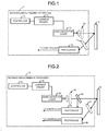
- FIG. 2 is a diagram illustrating a distance measurement apparatus 8 that measures a distance through the fight time measurement method.
- a controller 81 controls to drive a semiconductor laser 83 at a constant current via a current driver 82 . After laser light output by the semiconductor laser 83 is collimated by a collimating lens 84 , part of the laser light is taken out by a half mirror 85 and the laser light of this part is received by a photodiode 86 .
- the controller 81 starts to measure the flight time at a timing when the photodiode 86 receives the laser light.
- the measurement object 9 is irradiated with the laser light passing through the half mirror 85 .
- the laser light reflected by the measurement object 9 is received by the photodiode 88 through a light receiving lens 87 .
- the controller 81 terminates the measurement of the flight time of the laser light at a timing when the photodiode 88 receives the laser light.
- the controller 81 can measure the distance from the semiconductor laser 83 to the measurement object 9 by calculating the flight time of the laser light.
- FIG. 1 is a diagram illustrating a distance measurement apparatus that measures a distance through a triangulation method
- FIG. 2 is a diagram illustrating a distance measurement apparatus that measures a distance through a fight time measurement method
- FIG. 3 is a diagram illustrating the structure of a distance measurement apparatus
- FIG. 4 is a diagram illustrating an output of a photodiode
- FIG. 5 is a timing chart illustrating operating principles of a gate section and a counter
- FIG. 6 is a flowchart illustrating a distance measurement processing
- FIG. 7 is a diagram illustrating the structure of main portions of a distance measurement apparatus.
- FIG. 8 is a diagram illustrating each measurement position of a measurement object.
- a distance measurement apparatus comprises a semiconductor laser and an acquisition section.
- the semiconductor laser outputs laser light through a laser element and receives a back beam output by the laser element through a built-in photodiode.
- the acquisition section counts time between a first timing when an output of the photodiode exceeds a first threshold value because the laser element starts to output the laser light and a second timing when the output of the photodiode exceeds a second threshold value higher than the first threshold value because the laser light is reflected by the measurement object and returns to the laser element, and acquires the counted time as flight time of the laser light from a moment when the laser light is output to a moment when the laser light is reflected by the measurement object and returns to calculate a distance from the laser element to the measurement object or displacement of the distance.
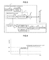
- FIG. 3 is a diagram illustrating the structure of a distance measurement apparatus 1 .
- the distance measurement apparatus 1 calculates flight time of laser light from a moment when the laser light is output to a moment when the laser light is reflected by the measurement object 9 and returns to calculate a distance to the measurement object 9 or displacement of the distance.
- a controller 11 of the distance measurement apparatus 1 is provided with a processor that controls various kinds of processing by reading programs in a memory (not shown), and controls the whole of the distance measurement apparatus 1 .
- the controller 11 controls to drive a laser element 131 of a semiconductor laser 13 via a current driver 12 at a constant current.
- the controller 11 controls to drive the laser element 131 in such a manner that a constant output of the laser light is continued during the measurement of the flight time of the laser light.
- the laser element 131 which is an edge-emitting laser diode, outputs laser light from one end surface. Further, the laser element 131 outputs a back beam from the other end surface opposite to one end surface in a direction opposite to the direction in which the laser light is output.
- the optical axis of the back beam and the optical axis of the laser light are on the identical straight line.
- the back beam is received by the photodiode 132 built in the semiconductor laser 13 .
- the photodiode 132 arranged to be adjacent to the laser element 131 is integrally packaged with the laser element 131 .
- Light emission efficiency of the laser element 131 reduces as the temperature becomes higher, and the output of the laser light changes according to the environment temperature.
- the intensity of the back beam is in proportion to the output of the laser light.
- the photodiode 132 for monitoring of back beam built in the semiconductor laser 13 is used, and the acquisition section 14 calculates the flight time of the laser light.
- the acquisition section 14 regards a timing when the photodiode 132 starts to receive the back beam as a timing when the laser light is output towards the measurement object 9 , that is, a measurement start timing of the flight time of the laser light.
- the measurement object 9 is irradiated with the laser light output by the laser element 131 via a collimating lens 15 .
- the laser light reflected by the measurement object 9 enters into the laser element 131 .
- the laser light entering into the laser element 131 resonates with the output laser light in the laser element 131 to increase the output of the back beam.
- the acquisition section 14 regards a timing when the output of the photodiode 132 is increased through the increase of the output of the back beam as a timing when the laser light is reflected by the measurement object 9 and returns to the laser element 131 , that is, a measurement end timing of the flight time of the laser light.
- the acquisition section 14 on the basis of the output of the photodiode 132 , acquires a difference between a timing when the laser element 131 starts to output the laser light and the timing when the laser light is reflected by the measurement object 9 and returns to the laser element 131 as the flight time of the laser light.
- the acquisition section 14 counts the flight time of the laser light and outputs a signal indicating the flight time of the laser light to the controller 11 .
- Such an acquisition section 14 comprises a conversion circuit (not shown) that converts a current output by the photodiode 132 into a voltage, an amplifier 141 that amplifies the output of the photodiode 132 passing the conversion circuit, first and second comparators 142 and 143 into which the output of the photodiode 132 passing the amplifier 141 is input, and a gate section 144 and a counter 145 arranged at the latter part of the first and second comparators 142 and 143 .
- the first and second comparators 142 and 143 , the gate section 144 , and the counter 145 are described later.
- the controller 11 calculates a distance to the measurement object 9 . Further, the controller 11 can calculate displacement of the distance to the measurement object 9 and can measure a surface shape of the measurement object 9 by causing the semiconductor laser 13 and the collimating lens 15 , and the measurement object 9 to relatively move in a direction orthogonal to an optical axis of the laser light (in the vertical direction of the paper surface of FIG. 3 ).
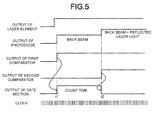
- FIG. 4 is a diagram illustrating the output of the photodiode 132 .
- horizontal axis represents time and vertical axis represents the output of the photodiode 13 .
- the output of the photodiode 132 is zero.
- a small amount of bias current is input to the laser element 131 to enable the laser element 131 to emit glimmer in some cases.
- the output of the photodiode 132 becomes a value corresponding to light receiving amount of a weak back beam until a timing t 1 when the laser light for measurement is output.
- the output of the photodiode 132 is increased in correspondence with the light receiving amount of the back beam.
- the output of the first comparator 142 is binary, and the output differs depending on whether or not the output of the photodiode 132 exceeds a threshold value th 1 (a first threshold value). Specifically, an output voltage of the first comparator 142 becomes high in a case in which an output voltage of the photodiode 132 input to a first input terminal exceeds a reference voltage th 1 as a threshold value input to a second input terminal, and the output voltage thereof becomes low in a case in which the output voltage of the photodiode 132 is smaller than the reference voltage th 1 .
- the threshold value th 1 is set to a value lower than the output of the photodiode 132 at the timing t 1 .
- the threshold value th 1 is set to a value higher than the output of the photodiode 132 at the time of the reception of the back beam caused by the bias current in a case of inputting the bias current to the laser element 131 .
- the resonance in the laser element 131 occurs through the returned laser light, and the output of the back beam is increased.
- the output of the photodiode 132 receiving the back beam is further increased.
- the second comparator 143 has the same structure as the first comparator 142 , but differs from the first comparator 142 only in a threshold value th 2 .
- the threshold value th 2 is set to a value lower than the output of the photodiode 132 at the timing t 2 and higher than the output of the photodiode 132 at the timing t 1 .
- the intensity of the laser light reflected by the measurement object 9 and returning to the laser element 131 varies according to the distance from the distance measurement apparatus 1 to the measurement object 9 and the reflectance of the measurement object 9 .
- the threshold value th 2 and the threshold value th 1 (reference voltages th 1 and th 2 of the comparators 142 and 143 ) for determining whether or not the laser light returns to the laser element 131 can be changed randomly by the controller 11 .
- FIG. 5 is a timing chart illustrating operating principles of the gate section 144 and the counter 145 .
- an output of the gate section 144 is high, and in a case in which the combination of the output of the first comparator 142 and that of the second comparator 143 is other situations except the above, the output of the gate section 144 is low.
- the output of the gate section 144 is high during a period from a moment when the laser light is output to a moment when the laser light is reflected by the measurement object 9 and returns.
- the counter 145 counts time using a clock and calculates the flight time of the laser light when the output of the gate section 144 is high.
- the controller 11 on the basis of the measured value of the counter 145 , calculates the distance to the measurement object 9 or the displacement of the distance.
- the controller 11 calculates a distance L from the distance measurement apparatus 1 (the laser element 131 ) to the measurement object 9 according to the following formula (1).
- the flight time of the laser light measured by the counter 145 is set to t
- a distance measurement processing carried out by the distance measurement apparatus 1 is simply described below with reference to a flowchart shown in FIG. 6 .
- the distance measurement apparatus 1 outputs laser light through the laser element 131 (Act 1 ).
- the photodiode 132 detects the back beam, and in this way, it can be determined that the laser element 131 is outputting the laser light.
- the distance measurement apparatus 1 monitors whether or not the output of the photodiode 132 exceeds the threshold value th 1 indicating the reception of the back beam (Act 2 ).
- the distance measurement apparatus 1 determines the timing t 1 when the output of the photodiode 132 exceeds the threshold value th 1 as a timing when the laser element 131 starts to output the laser light. The distance measurement apparatus 1 starts to measure the flight time of the laser light at the timing t 1 (Act 3 ).
- the returned laser light resonates with the output laser light in the laser element 131 , and the output of the back beam is increased.
- the photodiode 132 it can be determined that the laser light is reflected by the measurement object 9 and returns to the laser element 131 .
- the distance measurement apparatus 1 monitors whether or not the output of the photodiode 132 exceeds the threshold value th 2 indicating that the laser light returns to the laser element 131 (Act 4 ).
- the distance measurement apparatus 1 determines the timing t 2 as a timing when the laser light is reflected by the measurement object 9 and returns to the laser element 131 . Then, the distance measurement apparatus 1 ends the measurement of the flight time of the laser light at the timing t 2 (Act 5 ).
- the distance measurement apparatus 1 calculates a distance to the measurement object 9 or displacement of the distance (Act 6 ).
- FIG. 7 is a diagram illustrating the structure of main portions of a distance measurement apparatus 1 A.
- the distance measurement apparatus 1 A is provided with a galvanometer mirror 16 , which is different from the distance measurement apparatus 1 , other constitutions thereof are identical to those of the distance measurement apparatus 1 .
- the galvanometer mirror 16 is inclinable in any direction through a drive module (not shown), and can direct the laser light to any two-dimensional direction.
- an output direction of the laser light can be designated in a coordinate (X, Y), and the controller 11 controls an angle of the galvanometer mirror 16 so that a position of the coordinate (X, Y) is irradiated with the laser light.
- FIG. 8 is a diagram illustrating each measurement position of a measurement object 9 .
- the controller 11 drives the galvanometer mirror 16 to scan the laser light in a horizontal scanning direction at a position of which the coordinate is Y 0 in a vertical scanning direction.
- the controller 11 first emits the laser light to a position (X 0 , Y 0 ) (a first position) and measures flight time of the laser light to the position (X 0 , Y 0 ). The controller 11 , at this time, maintains an irradiation position of the laser light at the position (X 0 , Y 0 ) until the measurement of the flight time of the laser light at the position (X 0 , Y 0 ) is terminated.
- the controller 11 drives the galvanometer mirror 16 to cause the irradiation position of the laser light to move to a position (X 1 , Y 0 ) obtained by shifting one coordinate in the horizontal scanning direction and measures flight time of the laser light to the position (X 1 ,Y 0 ) (a second position).
- the controller 11 shifts the laser light every one coordinate in the horizontal scanning direction and scans the laser light in the horizontal scanning direction. Then, the controller 11 measures the flight time of the laser light at each coordinate position in the horizontal scanning direction.
- the controller 11 scans the laser light in the horizontal scanning direction at a position Y 1 obtained by shifting one coordinate in the vertical scanning direction orthogonal to the horizontal scanning direction, and measures flight time of the laser light at coordinate positions (X 1 , Y 1 ) (X 2 , Y 1 ) . . . in the horizontal scanning direction.
- the controller 11 on the basis of the flight time of the laser light of each coordinate position acquired in this way, calculates a distance to each coordinate position or displacement of the distance to the coordinate position, i.e., a surface shape of the measurement object 9 .
- a scan pattern of the laser light may be made into a zigzag shape as stated above in the X-Y plane, or a spiral shape as long as the shape is suitable.
- the back beam is monitored by one photodiode 132 , and the measurement start timing t 1 and the measurement end timing t 2 of the flight time of the laser light are obtained.
- the device structure can be simplified and miniaturized.
- the photodiode 132 for monitoring built in the semiconductor laser 13 As the photodiode 132 for monitoring built in the semiconductor laser 13 is used, a ready-made semiconductor laser 13 can be used and the distance measurement apparatuses 1 and 1 A can be created easily.
Landscapes
- Physics & Mathematics (AREA)
- Engineering & Computer Science (AREA)
- Electromagnetism (AREA)
- Computer Networks & Wireless Communication (AREA)
- General Physics & Mathematics (AREA)
- Radar, Positioning & Navigation (AREA)
- Remote Sensing (AREA)
- Optical Radar Systems And Details Thereof (AREA)
- Measurement Of Optical Distance (AREA)
- Length Measuring Devices By Optical Means (AREA)
Abstract
A distance measurement apparatus comprises an acquisition section which counts time between a first timing when an output of a photodiode built in a semiconductor laser exceeds a first threshold value because a laser element of the semiconductor laser starts to output laser light and a second timing when the output of the photodiode exceeds a second threshold value higher than the first threshold value because the laser light is reflected by a measurement object and returns to the laser element, and acquires the counted time as flight time of the laser light from a moment when the laser light is output to a moment when the laser light is reflected by the measurement object and returns to calculate a distance from the laser element to the measurement object or displacement of the distance.
Description
This application is based upon and claims the benefit of priority from Japanese Patent Application No. P2015-118454, filed Jun. 11, 2015, the entire contents of which are incorporated herein by reference.
Embodiments described herein relate generally to a distance measurement technology with a fight time measurement method.
A distance measurement apparatus is known which can be used for measurement of the three-dimensional shape of a commodity or a component. In recent years, with the automation of production in a factory, a distance measurement apparatus which is small in size and cheap in cost is required to be capable of measuring at a high speed in a non-contact manner. Thus, a distance measurement apparatus (for example, see Japanese Unexamined Patent Application Publication No. Hei 6-213658) that measures a distance through a triangulation method using laser light and a distance measurement apparatus (for example, see Japanese Unexamined Patent Application Publication No. 2014-102072) that measures a distance through a fight time measurement method using laser light are developed.
In the distance measurement apparatus 7, a controller 71 controls to drive a semiconductor laser 73 via a current driver 72 at a constant current. A measurement object 9 is irradiated with laser light output by the semiconductor laser 73 via a condenser lens 74. The laser light reflected by the measurement object 9 makes a spot imaged on a photodiode 76 (position detection element) through a light receiving lens 75. The position of the spot changes depending on displacement amount of the laser light in an optical axis direction.
The controller 71, through a drive module (not shown), measures the displacement amount of the spot on the photodiode 76 while causing the distance measurement apparatus 7 and the measurement object 9 to move relatively in the vertical direction shown in FIG. 1 orthogonal to the optical axis of the laser light. In this way, the controller 71 can measure the displacement amount of the measurement object 9 in the optical axis direction to measure the surface shape of the measurement object 9.
However, there is a problem in the distance measurement apparatus 7 using the triangulation method that the range of a measurable distance to the measurement object 9 is extremely narrow.
In the distance measurement apparatus 8, a controller 81 controls to drive a semiconductor laser 83 at a constant current via a current driver 82. After laser light output by the semiconductor laser 83 is collimated by a collimating lens 84, part of the laser light is taken out by a half mirror 85 and the laser light of this part is received by a photodiode 86.
When the distance measurement apparatus 8 measures flight time of the laser light from a moment when the laser light is output to a moment when the laser light is reflected by the measurement object 9 and returns, the controller 81 starts to measure the flight time at a timing when the photodiode 86 receives the laser light.
The measurement object 9 is irradiated with the laser light passing through the half mirror 85. The laser light reflected by the measurement object 9 is received by the photodiode 88 through a light receiving lens 87. The controller 81 terminates the measurement of the flight time of the laser light at a timing when the photodiode 88 receives the laser light.
The controller 81 can measure the distance from the semiconductor laser 83 to the measurement object 9 by calculating the flight time of the laser light.
In accordance with an embodiment, a distance measurement apparatus comprises a semiconductor laser and an acquisition section. The semiconductor laser outputs laser light through a laser element and receives a back beam output by the laser element through a built-in photodiode. The acquisition section counts time between a first timing when an output of the photodiode exceeds a first threshold value because the laser element starts to output the laser light and a second timing when the output of the photodiode exceeds a second threshold value higher than the first threshold value because the laser light is reflected by the measurement object and returns to the laser element, and acquires the counted time as flight time of the laser light from a moment when the laser light is output to a moment when the laser light is reflected by the measurement object and returns to calculate a distance from the laser element to the measurement object or displacement of the distance.
Each embodiment is described below with reference to the accompanying drawings.
The distance measurement apparatus 1 calculates flight time of laser light from a moment when the laser light is output to a moment when the laser light is reflected by the measurement object 9 and returns to calculate a distance to the measurement object 9 or displacement of the distance.
A controller 11 of the distance measurement apparatus 1 is provided with a processor that controls various kinds of processing by reading programs in a memory (not shown), and controls the whole of the distance measurement apparatus 1. The controller 11 controls to drive a laser element 131 of a semiconductor laser 13 via a current driver 12 at a constant current. The controller 11 controls to drive the laser element 131 in such a manner that a constant output of the laser light is continued during the measurement of the flight time of the laser light.
The laser element 131, which is an edge-emitting laser diode, outputs laser light from one end surface. Further, the laser element 131 outputs a back beam from the other end surface opposite to one end surface in a direction opposite to the direction in which the laser light is output. The optical axis of the back beam and the optical axis of the laser light are on the identical straight line.
The back beam is received by the photodiode 132 built in the semiconductor laser 13. The photodiode 132 arranged to be adjacent to the laser element 131 is integrally packaged with the laser element 131.
Light emission efficiency of the laser element 131 reduces as the temperature becomes higher, and the output of the laser light changes according to the environment temperature. Herein, the intensity of the back beam is in proportion to the output of the laser light. Thus, by monitoring the back beam, it is known to carry out a feedback control that sets the output of the laser light to be constant.
In the present embodiment, the photodiode 132 for monitoring of back beam built in the semiconductor laser 13 is used, and the acquisition section 14 calculates the flight time of the laser light.
Specifically, the acquisition section 14 regards a timing when the photodiode 132 starts to receive the back beam as a timing when the laser light is output towards the measurement object 9, that is, a measurement start timing of the flight time of the laser light.
The measurement object 9 is irradiated with the laser light output by the laser element 131 via a collimating lens 15. The laser light reflected by the measurement object 9 enters into the laser element 131. The laser light entering into the laser element 131 resonates with the output laser light in the laser element 131 to increase the output of the back beam.
Thus, the acquisition section 14 regards a timing when the output of the photodiode 132 is increased through the increase of the output of the back beam as a timing when the laser light is reflected by the measurement object 9 and returns to the laser element 131, that is, a measurement end timing of the flight time of the laser light.
The acquisition section 14, on the basis of the output of the photodiode 132, acquires a difference between a timing when the laser element 131 starts to output the laser light and the timing when the laser light is reflected by the measurement object 9 and returns to the laser element 131 as the flight time of the laser light.
The acquisition section 14 counts the flight time of the laser light and outputs a signal indicating the flight time of the laser light to the controller 11.
Such an acquisition section 14 comprises a conversion circuit (not shown) that converts a current output by the photodiode 132 into a voltage, an amplifier 141 that amplifies the output of the photodiode 132 passing the conversion circuit, first and second comparators 142 and 143 into which the output of the photodiode 132 passing the amplifier 141 is input, and a gate section 144 and a counter 145 arranged at the latter part of the first and second comparators 142 and 143. The first and second comparators 142 and 143, the gate section 144, and the counter 145 are described later.
The controller 11, based on the flight time of the laser light, calculates a distance to the measurement object 9. Further, the controller 11 can calculate displacement of the distance to the measurement object 9 and can measure a surface shape of the measurement object 9 by causing the semiconductor laser 13 and the collimating lens 15, and the measurement object 9 to relatively move in a direction orthogonal to an optical axis of the laser light (in the vertical direction of the paper surface of FIG. 3 ).
When the laser element 131 does not output the laser light, the output of the photodiode 132 is zero. In order to easily output the laser light, usually, a small amount of bias current is input to the laser element 131 to enable the laser element 131 to emit glimmer in some cases. In this case, the output of the photodiode 132 becomes a value corresponding to light receiving amount of a weak back beam until a timing t1 when the laser light for measurement is output.
At the timing t1 when the laser element 131 starts the output of the laser light, the output of the photodiode 132 is increased in correspondence with the light receiving amount of the back beam.
The output of the first comparator 142 is binary, and the output differs depending on whether or not the output of the photodiode 132 exceeds a threshold value th1 (a first threshold value). Specifically, an output voltage of the first comparator 142 becomes high in a case in which an output voltage of the photodiode 132 input to a first input terminal exceeds a reference voltage th1 as a threshold value input to a second input terminal, and the output voltage thereof becomes low in a case in which the output voltage of the photodiode 132 is smaller than the reference voltage th1.
In this way, in a case in which the output of the first comparator 142 is high, it can be determined that the laser element 131 starts the output of the laser light. Further, the threshold value th1 is set to a value lower than the output of the photodiode 132 at the timing t1. The threshold value th1 is set to a value higher than the output of the photodiode 132 at the time of the reception of the back beam caused by the bias current in a case of inputting the bias current to the laser element 131.
At a timing t2 when the laser light reflected by the measurement object 9 returns to the laser element 131 and enters into the laser element 131, the resonance in the laser element 131 occurs through the returned laser light, and the output of the back beam is increased. Thus, at the timing t2, the output of the photodiode 132 receiving the back beam is further increased.
The second comparator 143 has the same structure as the first comparator 142, but differs from the first comparator 142 only in a threshold value th2. The threshold value th2 is set to a value lower than the output of the photodiode 132 at the timing t2 and higher than the output of the photodiode 132 at the timing t1.
In this way, in a case in which the output of the second comparator 143 is high, it can be determined that the laser light reflected by the measurement object 9 returns to the laser element 131.
The intensity of the laser light reflected by the measurement object 9 and returning to the laser element 131 varies according to the distance from the distance measurement apparatus 1 to the measurement object 9 and the reflectance of the measurement object 9. Thus, the threshold value th2 and the threshold value th1 (reference voltages th1 and th2 of the comparators 142 and 143) for determining whether or not the laser light returns to the laser element 131 can be changed randomly by the controller 11.
In a case in which the output of the first comparator 142 is high and the output of the second comparator is low, an output of the gate section 144 is high, and in a case in which the combination of the output of the first comparator 142 and that of the second comparator 143 is other situations except the above, the output of the gate section 144 is low.
In other words, the output of the gate section 144 is high during a period from a moment when the laser light is output to a moment when the laser light is reflected by the measurement object 9 and returns.
The counter 145 counts time using a clock and calculates the flight time of the laser light when the output of the gate section 144 is high.
The controller 11, on the basis of the measured value of the counter 145, calculates the distance to the measurement object 9 or the displacement of the distance.
For example, the controller 11 calculates a distance L from the distance measurement apparatus 1 (the laser element 131) to the measurement object 9 according to the following formula (1). In the formula (1), the flight time of the laser light measured by the counter 145 is set to t, and the speed of the laser light is set to c.
L=(½)*t*c (1)
L=(½)*t*c (1)
A distance measurement processing carried out by the distance measurement apparatus 1 is simply described below with reference to a flowchart shown in FIG. 6 .
The distance measurement apparatus 1 outputs laser light through the laser element 131 (Act 1).
As the laser element 131 also outputs a back beam when outputting the laser light, the photodiode 132 detects the back beam, and in this way, it can be determined that the laser element 131 is outputting the laser light.
Thus, the distance measurement apparatus 1 monitors whether or not the output of the photodiode 132 exceeds the threshold value th1 indicating the reception of the back beam (Act 2).
In a case in which the output of the photodiode 132 exceeds the threshold value th1 (YES in Act 2), the distance measurement apparatus 1 determines the timing t1 when the output of the photodiode 132 exceeds the threshold value th1 as a timing when the laser element 131 starts to output the laser light. The distance measurement apparatus 1 starts to measure the flight time of the laser light at the timing t1 (Act 3).
If the laser light is reflected by the measurement object 9 and returns to the laser element 131, the returned laser light resonates with the output laser light in the laser element 131, and the output of the back beam is increased. Thus, by detecting the increase of the output of the back beam through the photodiode 132, it can be determined that the laser light is reflected by the measurement object 9 and returns to the laser element 131.
Thus, the distance measurement apparatus 1 monitors whether or not the output of the photodiode 132 exceeds the threshold value th2 indicating that the laser light returns to the laser element 131 (Act 4).
In a case in which the output of the photodiode 132 exceeds the threshold value th2 (YES in Act 4), the distance measurement apparatus 1 determines the timing t2 as a timing when the laser light is reflected by the measurement object 9 and returns to the laser element 131. Then, the distance measurement apparatus 1 ends the measurement of the flight time of the laser light at the timing t2 (Act 5).
The distance measurement apparatus 1, on the basis of the flight time of the laser light, calculates a distance to the measurement object 9 or displacement of the distance (Act 6).
The distance measurement apparatus 1 A is provided with a galvanometer mirror 16, which is different from the distance measurement apparatus 1, other constitutions thereof are identical to those of the distance measurement apparatus 1.
The galvanometer mirror 16 is inclinable in any direction through a drive module (not shown), and can direct the laser light to any two-dimensional direction. In the present embodiment, an output direction of the laser light can be designated in a coordinate (X, Y), and the controller 11 controls an angle of the galvanometer mirror 16 so that a position of the coordinate (X, Y) is irradiated with the laser light.
The controller 11 drives the galvanometer mirror 16 to scan the laser light in a horizontal scanning direction at a position of which the coordinate is Y0 in a vertical scanning direction.
The controller 11 first emits the laser light to a position (X0, Y0) (a first position) and measures flight time of the laser light to the position (X0, Y0). The controller 11, at this time, maintains an irradiation position of the laser light at the position (X0, Y0) until the measurement of the flight time of the laser light at the position (X0, Y0) is terminated.
Next, the controller 11 drives the galvanometer mirror 16 to cause the irradiation position of the laser light to move to a position (X1, Y0) obtained by shifting one coordinate in the horizontal scanning direction and measures flight time of the laser light to the position (X1,Y0) (a second position).
In this way, the controller 11 shifts the laser light every one coordinate in the horizontal scanning direction and scans the laser light in the horizontal scanning direction. Then, the controller 11 measures the flight time of the laser light at each coordinate position in the horizontal scanning direction.
If the measurement in the horizontal scanning direction is terminated, the controller 11 scans the laser light in the horizontal scanning direction at a position Y1 obtained by shifting one coordinate in the vertical scanning direction orthogonal to the horizontal scanning direction, and measures flight time of the laser light at coordinate positions (X1, Y1) (X2, Y1) . . . in the horizontal scanning direction.
The controller 11, on the basis of the flight time of the laser light of each coordinate position acquired in this way, calculates a distance to each coordinate position or displacement of the distance to the coordinate position, i.e., a surface shape of the measurement object 9.
A scan pattern of the laser light may be made into a zigzag shape as stated above in the X-Y plane, or a spiral shape as long as the shape is suitable.
In the first and second embodiments, the back beam is monitored by one photodiode 132, and the measurement start timing t1 and the measurement end timing t2 of the flight time of the laser light are obtained. Thus, in the first and second embodiments, compared with the conventional structure shown in FIG. 2 that uses the half mirror 85 and plural photodiodes 86 and 88, the device structure can be simplified and miniaturized.
In the first and second embodiments, as the photodiode 132 for monitoring built in the semiconductor laser 13 is used, a ready-made semiconductor laser 13 can be used and the distance measurement apparatuses 1 and 1A can be created easily.
Claims (6)
1. A distance measurement apparatus, comprising:
a semiconductor laser comprising an edge-emitting laser diode that produces a constant first output of laser light through a first edge in a first direction and produces a constant second output of laser light through a second edge in a second direction opposite the first direction;
a photodiode adjacent to and coupled with the edge-emitting laser diode, the photodiode integrally packaged with the edge-emitting laser diode, and
an acquisition section comprising a conversion circuit for converting a current output by the photodiode into a voltage, an amplifier for amplifying the voltage, a first comparator and a second comparator into which the voltage is input, and a gate section and a counter coupled to an output of the first comparator and the second comparator, the acquisition section configured to count time between a first timing when output laser light through the first edge exceeds a first threshold value and a second timing when the output of the photodiode exceeds a second threshold value higher than the first threshold value when the laser light is reflected by the measurement object and returns to the laser element, and acquires the counted time as flight time of the laser light from a moment when the laser light is output to a moment when the laser light is reflected by the measurement object and returns to calculate a distance from the laser element to the measurement object or displacement of the distance.
2. The distance measurement apparatus according to claim 1 , wherein
the
first comparator of the acquisition section is configured to carry out a first different output according to whether or not the output of the photodiode exceeds the first threshold value;
the second comparator of the acquisition section is configured to carry out a second different output according to whether or not the output of the photodiode exceeds the second threshold value; and
a counter configured to count elapsed time between a first time when the output of the first comparator exceeds the first threshold value and a second time when the output of the second comparator exceeds the second threshold value as the flight time; and
the first threshold value and the second threshold value can be changed.
3. The distance measurement apparatus according to claim 1 , wherein
the laser element continues the output of the laser light in the measurement of the flight time.
4. The distance measurement apparatus according to claim 2 , wherein
the laser element continues the output of the laser light in the measurement of the flight time.
5. The distance measurement apparatus according to claim 1 , further comprising
a mirror configured to reflect the laser light output by the laser element and change an output direction of the laser light; and
a controller configured to control an angle of the mirror and after scanning the laser light in a horizontal scanning direction, scan the laser light in the horizontal scanning direction at a position shifted in a vertical scanning direction.
6. The distance measurement apparatus according to claim 5 , wherein
the controller maintains an irradiation position of the laser light at a first position of the measurement object until the measurement of the flight time is terminated at the first position, and cause the irradiation position of the laser light to move to a second position shifted from the first position of the measurement object in the horizontal scanning direction if the measurement of the flight time at the first position is terminated.
Applications Claiming Priority (2)
| Application Number | Priority Date | Filing Date | Title |
|---|---|---|---|
| JP2015118454A JP2017003461A (en) | 2015-06-11 | 2015-06-11 | Distance measurement device |
| JP2015-118454 | 2015-06-11 |
Publications (2)
| Publication Number | Publication Date |
|---|---|
| US20160363667A1 US20160363667A1 (en) | 2016-12-15 |
| US9651663B2 true US9651663B2 (en) | 2017-05-16 |
Family
ID=56117627
Family Applications (1)
| Application Number | Title | Priority Date | Filing Date |
|---|---|---|---|
| US15/151,586 Active US9651663B2 (en) | 2015-06-11 | 2016-05-11 | Distance measurement apparatus |
Country Status (4)
| Country | Link |
|---|---|
| US (1) | US9651663B2 (en) |
| EP (1) | EP3104193A1 (en) |
| JP (1) | JP2017003461A (en) |
| CN (1) | CN106249249B (en) |
Cited By (1)
| Publication number | Priority date | Publication date | Assignee | Title |
|---|---|---|---|---|
| US20190178994A1 (en) * | 2017-12-07 | 2019-06-13 | Hon Hai Precision Industry Co., Ltd. | Laser distance measuring device |
Families Citing this family (7)
| Publication number | Priority date | Publication date | Assignee | Title |
|---|---|---|---|---|
| WO2018176288A1 (en) * | 2017-03-29 | 2018-10-04 | 深圳市大疆创新科技有限公司 | Laser radar and time measurement method based on laser radar |
| KR20190120715A (en) * | 2018-04-16 | 2019-10-24 | 리지텍 일렉트로닉스 컴퍼니 리미티드 | Structured light projection system |
| DE102018115452A1 (en) * | 2018-06-27 | 2020-01-02 | Carl Zeiss Ag | Method and device for scanning the distance of an object |
| CN111366239A (en) * | 2018-12-26 | 2020-07-03 | 中国科学院长春光学精密机械与物理研究所 | Laser irradiation time detection system and detection method |
| KR102198941B1 (en) * | 2019-01-03 | 2021-01-05 | 울산과학기술원 | Apparatus and Method for measuring distance using SPAD(Single Photon Avalanche Diode) using TOF(Time of Flight) |
| DE102019106750B4 (en) * | 2019-03-18 | 2021-02-04 | Sick Ag | Optical scanner |
| US20220336272A1 (en) * | 2021-04-15 | 2022-10-20 | Taiwan Semiconductor Manufacturing Co., Ltd. | Apparatus and methods for determining horizontal position of substrate using lasers |
Citations (8)
| Publication number | Priority date | Publication date | Assignee | Title |
|---|---|---|---|---|
| US20080186470A1 (en) * | 2006-09-15 | 2008-08-07 | Triple-In Holding Ag | Taking distance images |
| US20120069322A1 (en) * | 2008-06-27 | 2012-03-22 | Juha Kostamovaara | Method and Device For Measuring Distance |
| US20120176593A1 (en) * | 2011-01-10 | 2012-07-12 | Frucht Systems, Technologies and Business Development | Laser range finder and method for intrusion detection |
| US20130135420A1 (en) * | 2011-11-29 | 2013-05-30 | Kyocera Document Solutions Inc. | Optical scanning device, image forming apparatus with optical scanning device and abnormality detection method for optical scanning device |
| US20140233012A1 (en) * | 2009-06-26 | 2014-08-21 | Trimble Ab | Distance measuring device |
| US20160202214A1 (en) | 2015-01-14 | 2016-07-14 | Toshiba Tec Kabushiki Kaisha | Structural deformation detecting device |
| US20160202216A1 (en) | 2015-01-14 | 2016-07-14 | Toshiba Tec Kabushiki Kaisha | Structural deformation detecting device |
| US20160202215A1 (en) | 2015-01-14 | 2016-07-14 | Toshiba Tec Kabushiki Kaisha | Vibration measuring apparatus |
Family Cites Families (14)
| Publication number | Priority date | Publication date | Assignee | Title |
|---|---|---|---|---|
| JPS51126846A (en) * | 1975-04-28 | 1976-11-05 | Agency Of Ind Science & Technol | A data processing system |
| JP2885807B2 (en) * | 1988-10-21 | 1999-04-26 | 東京航空計器株式会社 | Distance detection device |
| JP2646898B2 (en) * | 1991-07-30 | 1997-08-27 | 日本電気株式会社 | Laser distance measuring device |
| US5267016A (en) * | 1991-11-27 | 1993-11-30 | United Technologies Corporation | Laser diode distance measurement |
| DE4229313A1 (en) | 1992-09-02 | 1994-03-03 | Betr Forsch Inst Angew Forsch | Method and device for high-precision distance measurement of surfaces |
| JP3225682B2 (en) * | 1993-03-30 | 2001-11-05 | 住友電気工業株式会社 | Distance measuring device |
| JPH0763853A (en) * | 1993-08-30 | 1995-03-10 | Omron Corp | Device of measuring distance |
| JP2001183461A (en) * | 1999-12-27 | 2001-07-06 | Minolta Co Ltd | Distance-measuring device |
| JP4037774B2 (en) * | 2003-02-19 | 2008-01-23 | 富士通テン株式会社 | Radar equipment |
| JP4071688B2 (en) * | 2003-05-12 | 2008-04-02 | ローム株式会社 | Vibration measuring method and apparatus |
| JP5172077B2 (en) * | 2005-05-06 | 2013-03-27 | アズビル株式会社 | Distance / speed meter and distance / speed measurement method |
| CN100362366C (en) * | 2006-04-30 | 2008-01-16 | 太原理工大学 | Apparatus and method for distance measurement using chaos laser of optical fiber laser device |
| JP5651289B2 (en) * | 2008-03-25 | 2015-01-07 | アズビル株式会社 | Reflective photoelectric switch and object detection method |
| JP2014102072A (en) | 2011-03-08 | 2014-06-05 | National Univ Corp Shizuoka Univ | Signal processing circuit for distance measurement and distance measurement device |
-
2015
- 2015-06-11 JP JP2015118454A patent/JP2017003461A/en active Pending
-
2016
- 2016-05-11 US US15/151,586 patent/US9651663B2/en active Active
- 2016-06-02 CN CN201610384320.0A patent/CN106249249B/en not_active Expired - Fee Related
- 2016-06-10 EP EP16173928.9A patent/EP3104193A1/en not_active Withdrawn
Patent Citations (8)
| Publication number | Priority date | Publication date | Assignee | Title |
|---|---|---|---|---|
| US20080186470A1 (en) * | 2006-09-15 | 2008-08-07 | Triple-In Holding Ag | Taking distance images |
| US20120069322A1 (en) * | 2008-06-27 | 2012-03-22 | Juha Kostamovaara | Method and Device For Measuring Distance |
| US20140233012A1 (en) * | 2009-06-26 | 2014-08-21 | Trimble Ab | Distance measuring device |
| US20120176593A1 (en) * | 2011-01-10 | 2012-07-12 | Frucht Systems, Technologies and Business Development | Laser range finder and method for intrusion detection |
| US20130135420A1 (en) * | 2011-11-29 | 2013-05-30 | Kyocera Document Solutions Inc. | Optical scanning device, image forming apparatus with optical scanning device and abnormality detection method for optical scanning device |
| US20160202214A1 (en) | 2015-01-14 | 2016-07-14 | Toshiba Tec Kabushiki Kaisha | Structural deformation detecting device |
| US20160202216A1 (en) | 2015-01-14 | 2016-07-14 | Toshiba Tec Kabushiki Kaisha | Structural deformation detecting device |
| US20160202215A1 (en) | 2015-01-14 | 2016-07-14 | Toshiba Tec Kabushiki Kaisha | Vibration measuring apparatus |
Cited By (1)
| Publication number | Priority date | Publication date | Assignee | Title |
|---|---|---|---|---|
| US20190178994A1 (en) * | 2017-12-07 | 2019-06-13 | Hon Hai Precision Industry Co., Ltd. | Laser distance measuring device |
Also Published As
| Publication number | Publication date |
|---|---|
| CN106249249B (en) | 2018-11-09 |
| US20160363667A1 (en) | 2016-12-15 |
| JP2017003461A (en) | 2017-01-05 |
| EP3104193A1 (en) | 2016-12-14 |
| CN106249249A (en) | 2016-12-21 |
Similar Documents
| Publication | Publication Date | Title |
|---|---|---|
| US9651663B2 (en) | Distance measurement apparatus | |
| JP6819098B2 (en) | Object detection device, sensing device and mobile device | |
| US20180209779A1 (en) | Laser sensor for partical density detection | |
| JP4694907B2 (en) | Read head for speckle image correlated optical displacement sensing, read head for speckle image correlated optical position transducer, and method for monitoring warm-up period thereof | |
| JP6700586B2 (en) | Circuit device, photodetector, object detection device, sensing device, mobile device, signal detection method and object detection method | |
| EP3147690B1 (en) | Circuit device, optical detector, object detector, sensor, and movable device | |
| US9981604B2 (en) | Object detector and sensing apparatus | |
| US20210293942A1 (en) | Method of calculating distance-correction data, range-finding device, and mobile object | |
| US20170199272A1 (en) | Optical reflection sensor and electronic device | |
| US9329025B2 (en) | Measuring device | |
| JP2019158693A (en) | Light reception device, object detection device, distance measurement device, moving body device, noise measurement method, object detection method, and distance measurement method | |
| US20190178996A1 (en) | Distance measuring device | |
| US10859681B2 (en) | Circuit device, object detecting device, sensing device, mobile object device and object detecting device | |
| KR20200101860A (en) | Random hardware fault and degradation protection apparatus for time-of-flight receiver | |
| WO2020031881A1 (en) | Optical distance measurement device | |
| US20170038203A1 (en) | Self-propelled device and distance detector thereof | |
| JP2013190378A (en) | Optical sensor and setting method for sensitivity adjustment control | |
| JP6186863B2 (en) | Ranging device and program | |
| JP6566198B2 (en) | Object detection device, sensing device, mobile device, and object detection method | |
| JP5903855B2 (en) | Optical displacement sensor | |
| US20200292667A1 (en) | Object detector | |
| CN101156073A (en) | Relative movement sensor comprising multiple lasers | |
| KR101604867B1 (en) | Sensing appratus for using diffraction grating | |
| US20200175706A1 (en) | Three-dimensional position detecting device, three-dimensional position detecting system and method for detecting three-dimensional positions | |
| JP5760938B2 (en) | Optical sensor |
Legal Events
| Date | Code | Title | Description |
|---|---|---|---|
| AS | Assignment |
Owner name: TOSHIBA TEC KABUSHIKI KAISHA, JAPAN Free format text: ASSIGNMENT OF ASSIGNORS INTEREST;ASSIGNORS:ISHIKAWA, DAISUKE;KOMIYA, KENICHI;REEL/FRAME:038544/0175 Effective date: 20160428 |
|
| STCF | Information on status: patent grant |
Free format text: PATENTED CASE |
|
| MAFP | Maintenance fee payment |
Free format text: PAYMENT OF MAINTENANCE FEE, 4TH YEAR, LARGE ENTITY (ORIGINAL EVENT CODE: M1551); ENTITY STATUS OF PATENT OWNER: LARGE ENTITY Year of fee payment: 4 |