JP6186863B2 - Ranging device and program - Google Patents
Ranging device and program Download PDFInfo
- Publication number
- JP6186863B2 JP6186863B2 JP2013097863A JP2013097863A JP6186863B2 JP 6186863 B2 JP6186863 B2 JP 6186863B2 JP 2013097863 A JP2013097863 A JP 2013097863A JP 2013097863 A JP2013097863 A JP 2013097863A JP 6186863 B2 JP6186863 B2 JP 6186863B2
- Authority
- JP
- Japan
- Prior art keywords
- angle
- scanning mirror
- light
- distance
- light receiving
- Prior art date
- Legal status (The legal status is an assumption and is not a legal conclusion. Google has not performed a legal analysis and makes no representation as to the accuracy of the status listed.)
- Expired - Fee Related
Links
- 238000005259 measurement Methods 0.000 claims description 150
- 238000012545 processing Methods 0.000 claims description 23
- 238000009434 installation Methods 0.000 claims description 4
- 238000000034 method Methods 0.000 description 16
- 230000008569 process Effects 0.000 description 11
- 238000001514 detection method Methods 0.000 description 8
- 230000003287 optical effect Effects 0.000 description 8
- 230000006870 function Effects 0.000 description 7
- 230000008859 change Effects 0.000 description 4
- 238000006243 chemical reaction Methods 0.000 description 4
- 238000010586 diagram Methods 0.000 description 4
- 238000012544 monitoring process Methods 0.000 description 3
- 239000011159 matrix material Substances 0.000 description 2
- 239000004065 semiconductor Substances 0.000 description 2
- 238000003491 array Methods 0.000 description 1
- 230000001427 coherent effect Effects 0.000 description 1
- 238000004891 communication Methods 0.000 description 1
- 238000005516 engineering process Methods 0.000 description 1
- 238000003384 imaging method Methods 0.000 description 1
- 238000012986 modification Methods 0.000 description 1
- 230000004048 modification Effects 0.000 description 1
- 230000004044 response Effects 0.000 description 1
Images


Landscapes
- Physics & Mathematics (AREA)
- Engineering & Computer Science (AREA)
- Electromagnetism (AREA)
- Computer Networks & Wireless Communication (AREA)
- General Physics & Mathematics (AREA)
- Radar, Positioning & Navigation (AREA)
- Remote Sensing (AREA)
- Traffic Control Systems (AREA)
- Optical Radar Systems And Details Thereof (AREA)
Description
本開示は、測距装置及びプログラムに関する。 The present disclosure relates to a distance measuring apparatus and a program.
従来から、レーザ光源からのレーザ光を光走査手段で走査し、走査領域からの反射光を前記走査レーザ光と異なる光路で受光して走査領域内を監視する走査型レーザレーダが知られている(例えば、特許文献1参照)。この走査型レーザレーダは、多数の受光素子がマトリクス状に配列された受光素子アレイを備える。走査領域からの反射光は、結像レンズを介して受光素子アレイにより受光される。この走査型レーザレーダでは、光走査手段の走査位置が変化する毎に、変換テーブルメモリ内の変換テーブルに基づいて、各走査位置に対して予め対応付けられた受光素子及びその周囲の受光素子がマルチプレクサにより選択される。選択された受光素子の受光出力は加算され、加算された受光出力に基づいて走査領域内が監視される。 2. Description of the Related Art Conventionally, there is known a scanning laser radar that scans laser light from a laser light source with an optical scanning unit and receives reflected light from a scanning area through an optical path different from the scanning laser light to monitor the inside of the scanning area. (For example, refer to Patent Document 1). This scanning laser radar includes a light receiving element array in which a large number of light receiving elements are arranged in a matrix. The reflected light from the scanning region is received by the light receiving element array through the imaging lens. In this scanning laser radar, each time the scanning position of the optical scanning unit changes, a light receiving element previously associated with each scanning position and its surrounding light receiving elements are determined based on the conversion table in the conversion table memory. Selected by multiplexer. The light receiving outputs of the selected light receiving elements are added, and the inside of the scanning region is monitored based on the added light receiving outputs.
上記の特許文献1に記載の構成では、マルチプレクサにより選択された受光素子の受光出力のみを用いるため、監視対象以外からの光による受光出力は利用されず、ノイズ成分を軽減することができる。即ち、走査による広角な監視を可能としつつ、ノイズ成分を軽減することができる。
In the configuration described in
しかしながら、上記の特許文献1に記載の構成では、多数の受光素子(受光素子アレイ)や、マルチプレクサ、変換テーブルメモリ等を必要とし、回路規模が大掛かりになるという問題点がある。
However, the configuration described in
そこで、開示の技術は、回路規模を増大させることなく、近距離に位置する測定対象物の測距精度を高めることが可能な測距装置及びプログラムの提供を目的とする。 Therefore, the disclosed technique aims to provide a distance measuring device and a program capable of increasing the distance measuring accuracy of a measurement object located at a short distance without increasing the circuit scale.
本開示の一局面によれば、光源と、
前記光源からの光線を反射することにより外部に出射し、前記光線の出射方向が変化するように角度が制御される第1走査ミラーと、
受光素子と、
外部から入射する光線を前記受光素子に向けて反射し、外部の複数方向から入射する光線のうち、前記受光素子に受光される方向の光線が変化するように角度が制御される第2走査ミラーと、
前記受光素子の受光出力に基づいて、外部に存在する測定対象物までの距離を算出する距離測定部と、
前記測定対象物までの距離に関する距離情報と、前記光線の出射時の前記第1走査ミラーの角度に関する角度情報とに基づいて、前記第2走査ミラーの角度を制御する制御装置とを含み、
前記距離情報は、前記距離測定部の算出結果に基づいて生成される、測距装置が提供される。
According to one aspect of the present disclosure, a light source;
A first scanning mirror that emits the light from the light source to the outside by reflecting the light, and the angle is controlled so that the emission direction of the light changes;
A light receiving element;
A second scanning mirror that reflects light incident from the outside toward the light receiving element and controls the angle so that the light in the direction received by the light receiving element among the light incident from a plurality of external directions changes. When,
Based on the light receiving output of the light receiving element, a distance measuring unit that calculates a distance to a measurement object existing outside,
And distance information on the distance to the measurement object, based on the angle with respect to the angle information of the first scanning mirror during the emission of the light beam, seen including a control device for controlling the angle of the second scanning mirror,
A distance measuring device is provided in which the distance information is generated based on a calculation result of the distance measuring unit .
本開示の技術によれば、回路規模を増大させることなく、近距離に位置する測定対象物の測距精度を高めることが可能な測距装置等が得られる。 According to the technology of the present disclosure, it is possible to obtain a distance measuring device or the like that can increase the distance measuring accuracy of a measurement object located at a short distance without increasing the circuit scale.
以下、添付図面を参照しながら各実施例について詳細に説明する。 Hereinafter, embodiments will be described in detail with reference to the accompanying drawings.
図1は、測距装置1の一例を示す構成図である。図1においては、光線70A,70Bが2点鎖線で示されている。また、図1においては、光学装置200は、便宜上、上面視で示されている。光線70Aは、測定対象物までの往路に係る光線を示し、光線70Bは、測定対象物までの復路に係る光線を示す。
FIG. 1 is a configuration diagram illustrating an example of a
測距装置1は、外部の測定対象物を検知し、当該測定対象物までの距離(測距装置1と当該測定対象物との間の距離)を測定する。測距装置1は、任意の用途で使用されてもよい。例えば、測距装置1は、車両周囲の測定対象物を検知するために、車両に搭載されてもよい。この場合、測距装置1による測定対象物の検知結果(又は測定対象物までの距離の測定結果)は、測定対象物に対する注意喚起のための警報や、測定対象物との衝突を回避するための衝突防止制御(プリクラッシュ制御)等で利用されてもよい。
The distance measuring
測距装置1は、図1に示すように、処理装置100と、光学装置200とを含む。
As shown in FIG. 1, the
処理装置100は、任意の形態で構成されてもよい。処理装置100の各種機能(以下で説明する機能を含む)は、任意のハードウェア、ソフトウェア、ファームウェア又はそれらの組み合わせにより実現されてもよい。例えば、処理装置100の機能の任意の一部又は全部は、特定用途向けASIC(application-specific integrated circuit)、FPGA(Field Programmable Gate Array)等により実現されてもよい。また、処理装置100は、物理的に離れた位置にある複数の処理装置により実現されてもよい。 The processing apparatus 100 may be configured in any form. Various functions (including functions described below) of the processing device 100 may be realized by arbitrary hardware, software, firmware, or a combination thereof. For example, any or all of the functions of the processing apparatus 100 may be realized by an application-specific integrated circuit (ASIC), a field programmable gate array (FPGA), or the like. The processing apparatus 100 may be realized by a plurality of processing apparatuses that are physically separated from each other.
処理装置100は、図1に示すように、レーザ駆動回路102と、第1走査ミラーコントローラ104と、受光出力アンプ106と、第2走査ミラーコントローラ108と、飛行時間(距離)測定回路110と、測定制御回路112とを含む。尚、これらの区分けは、便宜上のものであり、各回路等の機能が他の回路により実現されてもよい。例えば、第2走査ミラーコントローラ108の機能の一部または全部は、測定制御回路112により実現されてもよい。また、飛行時間測定回路110の一部または全部は、測定制御回路112により実現されてもよい。
As shown in FIG. 1, the processing apparatus 100 includes a
レーザ駆動回路102は、光源202から光線が出射されるように、光源202を駆動する。レーザ駆動回路102は、測定制御回路112からの出射指令に応じて、光源202を駆動してよい。レーザ駆動回路102は、光線の出射タイミングを表す情報を飛行時間測定回路110に供給してよい。
The
第1走査ミラーコントローラ104は、測定制御回路112からの角度指令(第1角度指令と称する)に応じて、第1走査ミラー204の角度β1を制御する。例えば、第1走査ミラーコントローラ104は、アクチュエータ(図示せず)を制御して、第1走査ミラー204の角度β1を変更させる。第1角度指令は、第1走査ミラー204の角度β1の指示値を含んでよい。第1走査ミラーコントローラ104は、第1走査ミラー204の角度β1を検出し、第1走査ミラー204の角度β1を表す情報(以下、角度情報とも称する)を生成して測定制御回路112に供給してよい。角度情報は、測定制御回路112からの第1角度指令に基づいて生成されてもよい。
The first
受光出力アンプ106は、受光素子206の受光出力を増幅し、飛行時間測定回路110に供給する。
The light
第2走査ミラーコントローラ108は、測定制御回路112からの角度指令(第2角度指令と称する)に応じて、第2走査ミラー208の角度β2を制御する。例えば、第2走査ミラーコントローラ108は、アクチュエータ(図示せず)を制御して、第2走査ミラー208の角度β2を変更させる。第2角度指令は、第2走査ミラー208の角度β2の指示値を含んでよい。
The second
飛行時間測定回路110は、受光出力アンプ106からの出力(受光素子206の受光出力)に基づいて、外部の測定対象物までの距離を算出(計測)する。例えば、飛行時間測定回路110は、光源202から出射されてから外部の測定対象物に当たって戻ってくるまでの光線の飛行時間(TOF:Time Of Flight)を測定することで、外部の測定対象物までの距離を算出する。算出した距離を表す情報(測距結果)は、測定制御回路112に供給される。尚、測定制御回路112は、このようにして得られた測距結果を、外部機器(例えば、車載の警報制御装置)に送信してもよい。
The time-of-
測定制御回路112は、レーザ駆動回路102、第1走査ミラーコントローラ104及び第2走査ミラーコントローラ108を制御することで、測距装置1の測距動作を制御する。また、測定制御回路112は、飛行時間測定回路110からの測距結果を取得し、例えば外部機器(例えば、車載の警報制御装置)に送信する。測定制御回路112の機能の詳細は後述する。
The
光学装置200は、光源202と、第1走査ミラー204と、受光素子206と、第2走査ミラー208と、集光レンズ210と、波長選択フィルタ212とを含む。
The
光源202は、任意であるが、本例では、可干渉性を持つレーザ光を発生するレーザ光源(例えば半導体レーザ装置)である。この場合、光源202は、例えばレーザダイオードにより形成されてよい。尚、レーザ光は、例えば0.7 μm〜1 mmの赤外線レーザ光であってよい。光源202は、例えば、パルスレーザ光を出射するようにレーザ駆動回路102により駆動されてよい。
The
第1走査ミラー204は、光源202からの光線を反射して外部に光線(光線70A参照)を出射する。即ち、第1走査ミラー204は、光源202から受けた光線を、外部に向けて反射する。第1走査ミラー204は、角度β1が可変に構成される。尚、光源202からの光線が到達する外部領域(測定対象物検知領域)の角度範囲は、第1走査ミラー204の回転範囲(角度β1の可変範囲)に応じて決定される。図1に示す例では、第1走査ミラー204は、水平面内での走査が可能な態様で、角度β1が可変に構成される。尚、ここでは、角度β1は、基準線L1の光源202側を0度として時計方向を正方向として増加する角度とする。基準線L1は、第1走査ミラー204の回転中心O1を通って水平面内で横方向に延在する線であるとする。第1走査ミラー204の角度β1は、上述の如く、アクチュエータ(図示せず)の駆動により可変されてよい。第1走査ミラー204及びアクチュエータは、例えば、MEMS(Micro Electro Mechanical Systems)により形成されてよい。
The
受光素子206は、第2走査ミラー208により反射された光線(光線70B参照)を受光し、受光量に応じた電気信号を出力してよい。受光素子206は、例えばフォトダイオードにより形成されてよい。受光素子206は、単一の受光素子であってよい。即ち、受光素子206は、多数の受光素子がマトリックス上に配列された受光素子アレイとして形成されてもよいが、好ましくは、回路規模を低減する観点から、単一の受光素子である。但し、受光素子206は、複数の受光素子の集合から形成されてもよい。
The
第2走査ミラー208は、外部(測定対象物検知領域を含む)から入射する光線(光線70B参照)を受けて、当該光線を受光素子206に向けて反射する。第2走査ミラー208は、外部の複数方向から入射する光線のうち、受光素子206に受光される方向の光線が変化するように角度β2が制御される。即ち、第2走査ミラー208の角度β2は、外部の複数方向から入射する光線のうちの、受光素子206に受光される光線の方向を決める。受光素子206に受光される光線の方向は、第2走査ミラー208の角度β2と、受光素子206と第2走査ミラー208の位置関係とによって定まる(図2参照)。図1に示す例では、第2走査ミラー208は、水平面内での走査が可能な態様で、角度β2が可変に構成される。尚、ここでは、角度β2は、基準線L2の受光素子206側を0度として時計方向を正方向として増加する角度とする。基準線L2は、第2走査ミラー208の回転中心O2を通って水平面内で横方向に延在する線であるとする。第2走査ミラー208の角度β2は、上述の如く、アクチュエータ(図示せず)の駆動により可変されてよい。第2走査ミラー208及びアクチュエータは、例えば、MEMSにより形成されてよい。尚、第2走査ミラー208と第1走査ミラー204とは、構成自体は同一であってよい。
The
集光レンズ210は、第2走査ミラー208と受光素子206との間の光路内に設けられてよい。集光レンズ210は、第2走査ミラー208により反射された光線を集光し、受光素子206上で合焦(結像)させる。
The
波長選択フィルタ212は、光源202から発生される光線の波長に対応する波長のみを透過するフィルタである。波長選択フィルタ212は、例えばバンドバスフィルタにより形成されてよい。波長選択フィルタ212は、第2走査ミラー208の前段に設けられる。即ち、外部からの光線は、波長選択フィルタ212を介して第2走査ミラー208に入射される。
The
図2は、角度β1及び角度β2等の説明図であり、(A)は、第1走査ミラー204の角度β1と光線70A(往路)の出射方向θ1との関係を模式的に示し、(B)は、第2走査ミラー208の角度β2と光線70B(復路)の入射方向θ2との関係を模式的に示す。尚、図2においては、便宜上、集光レンズ210の図示は省略されている。
FIG. 2 is an explanatory diagram of the angle β 1, the angle β 2, and the like. FIG. 2A schematically shows the relationship between the angle β 1 of the
第1走査ミラー204の角度β1と光線70A(往路)の出射方向θ1との関係は、図2(A)に示すように、以下の式で表される。
β1=(θ1−α1)/2 式(1)
ここで、α1は、光源202の設置角度、即ち、基準線L1に対する光源202からの光線の角度である。角度α1は、基準線L1の光源202側を0度として反時計方向を正方向として増加する角度とする。また、出射方向θ1は、基準線L1の光源202とは逆側を0度として時計方向を正方向として増加する角度とする。尚、図2(A)において、ラインC1は、第1走査ミラー204の回転中心O1を通る、第1走査ミラー204の表面(反射面)に対する法線を表す。尚、式(1)は、光源202からの光線とラインC1との間の角度(90−α1−β1)が、第1走査ミラー204で反射する光線70AとラインC1との間の角度(90−θ1+β1)に等しいことに基づく。
Relationship between the emission direction θ1 angle beta 1 and
β 1 = (θ1−α 1 ) / 2 Formula (1)
Here, α 1 is the installation angle of the
第2走査ミラー208の角度β2と光線70B(復路)の入射方向θ2との関係は、図2(B)に示すように、以下の式で表される。
β2=(θ2−α2)/2 式(2)
ここで、α2は、受光素子206の設置角度、即ち、基準線L2に対する受光素子206への光線の角度である。角度α2は、基準線L2の受光素子206側を0度として反時計方向を正方向として増加する角度とする。また、出射方向θ2は、基準線L2の受光素子206とは逆側を0度として時計方向を正方向として増加する角度とする。尚、図2(B)において、ラインC2は、第2走査ミラー208の回転中心O2を通る、第2走査ミラー208の表面(反射面)に対する法線を表す。尚、式(2)は、受光素子206に向かって反射する光線とラインC2との間の角度(90−α2−β2)が、角度(90−θ2+β2)に等しいことに基づく。この角度(90−θ2+β2)は、第2走査ミラー208に入射する光線70B(受光素子206に向かって反射することになる光線)とラインC2との間の角度である。
Relationship between the incident direction θ2 of the angle beta 2 and beam 70B of the second scanning mirror 208 (backward), as shown in FIG. 2 (B), is expressed by the following equation.
β 2 = (θ 2 −α 2 ) / 2 Formula (2)
Here, α 2 is the installation angle of the
次に、測定制御回路112による第2走査ミラーコントローラ108の制御方法、即ち第2走査ミラーコントローラ108の機能について説明する。
Next, the control method of the second
第2走査ミラーコントローラ108は、上述の如く、測定制御回路112からの第2角度指令に応じて、第2走査ミラー208の角度β2を制御する。即ち、第2走査ミラーコントローラ108は、第2角度指令による第2走査ミラー208の角度β2の指示値が実現されるように、第2走査ミラー208の角度β2を制御する。
As described above, the second
ここで、第2走査ミラー208の角度β2(第2角度指令の指示値)は、測定対象物までの距離に関する距離情報と、第1走査ミラー204の角度β1を表す情報(角度情報)とに基づいて、決定される。
Here, the angle β 2 of the second scanning mirror 208 (indicated value of the second angle command) is distance information related to the distance to the measurement object and information (angle information) indicating the angle β 1 of the
距離情報は、任意の態様で取得されてもよい。例えば、距離情報は、飛行時間測定回路110の測定結果に基づく情報であってもよい。この場合、距離情報は、前回以前の測定時に得られた同一の測定対象物までの距離の測定結果(飛行時間測定回路110の測定結果)に基づいて生成されてもよい。或いは、距離情報は、他の測位装置(例えば、ステレオカメラ)から取得されてもよい。かかる距離情報は、例えば、ステレオカメラを搭載する車両に測距装置1が搭載される場合に取得可能である。
The distance information may be acquired in any manner. For example, the distance information may be information based on the measurement result of the time-of-
尚、距離情報は、精度の高い情報であってよいが、非常に高い精度である必要はない。従って、測距装置1が車両に搭載される場合、距離情報は、車両位置と過去の測定対象物の検知結果との対応関係に基づいて取得されてもよい。例えば、ある車両位置で、測定対象物(例えば駐車場のポール等の固定物)が過去に検知された場合、当該車両位置と略同一の車両位置に位置するときに、当該過去の測定対象物の距離情報が利用されてもよい。また、測定対象物の位置は、ナビゲーション装置からの地図情報等、インフラからの情報、車車間通信で得られる情報等に基づいて、一次的に特定されてよい。この場合、かかる測定対象物の位置と、GPS(Global Positioning System)により測位される自車位置とに基づいて、距離情報が生成されてもよい。
The distance information may be highly accurate information, but need not be very accurate. Therefore, when the
角度情報は、今回の測定のための光線の出射時における第1走査ミラー204の角度β1を表す。角度情報は、任意の態様で取得されてもよい。例えば、角度情報は、センサ等で検出されてもよいし、制御値(第1角度指令)が使用されてもよい。
Angle information indicates the angle beta 1 of the
図3は、第2走査ミラー208の角度β2の決定方法の説明図であり、測距装置1と測定対象物S1との関係の一例を模式的に上面視で示す。尚、測距装置1については、第1走査ミラー204及び第2走査ミラー208のみを模式的に図示している。
Figure 3 is an explanatory view of the angle beta 2 of method for determining the
図3に示す例では、測定対象物S1は、測距装置1から距離X1だけ離間している。即ち、測距装置1の基準線L1、L2(ここでは、便宜上、同一としている)と測定対象物S1との間の距離は、X1である。また、測定対象物S1の横位置Y1は、第1走査ミラー204と第2走査ミラー208との間の中心軸Oを基準としている。中心軸Oは、第1走査ミラー204の中心O1と第2走査ミラー208の中心O2から等距離にある軸である。
In the example shown in FIG. 3, the measuring object S <b> 1 is separated from the
この場合、先ず、第1走査ミラー204の角度β1(図2(A)参照)、出射される光線70Aが測定対象物S1に当たるように設定(調整)される。このとき、第2走査ミラー208の角度β2(図2(B)参照)は、測定対象物S1からの光線(測定対象物S1にて反射した光線)70Bが受光素子206にて受光されるように決定される。即ち、第2走査ミラー208の角度β2は、他の方向から入射する光線(例えば、太陽光等の測定対象外の光線や、他の物体からの光)70C,70Dが受光素子206にて受光されないように決定される。
In this case, first, the angle β 1 (see FIG. 2A) of the
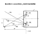
図4は、図3の状態を幾何学図形として主要部分だけを取り出した図である。図4に示すように、ここでは、第1走査ミラー204及び第2走査ミラー208と中心軸Oとの間の距離(横方向)をLとする。尚、この距離Lは、測距装置1の構造に依存する距離であり、既知である。
FIG. 4 is a diagram in which only the main part is extracted with the state of FIG. 3 as a geometric figure. As shown in FIG. 4, here, the distance (lateral direction) between the
図4に示す幾何的な関係から、以下の式(3)及び式(4)が導かれる。
tan(θ2)=X1/(Y1-L) 式(3)
tan(θ1)=X1/(Y1+L) 式(4)
式(3)及び式(4)から、以下の式(5)が導かれる。
θ2=arctan(X1/(X1cot(θ1)-2L) 式(5)
よって、上述の式(2)から、第2走査ミラー208の角度β2は、以下の式(6)に基づいて決定されてよい。
β2={arctan(X1/(X1cot(θ1)-2L)-α2}/2 式(6)
The following equations (3) and (4) are derived from the geometric relationship shown in FIG.
tan (θ2) = X1 / (Y1-L) Equation (3)
tan (θ1) = X1 / (Y1 + L) Equation (4)
The following equation (5) is derived from the equations (3) and (4).
θ2 = arctan (X1 / (X1cot (θ1) -2L) Equation (5)
Therefore, from the above equation (2), the angle β 2 of the
β 2 = {arctan (X1 / (X1cot (θ1) -2L) -α 2 } / 2 Formula (6)
ところで、測定対象物S1までの距離X1が非常に大きい場合(例えば、(X1cot(θ1)≫2Lの場合)は、式(5)からtan(θ2)≒tan(θ1)となる。従って、第2走査ミラー208の角度β2は、第1走査ミラー204の角度β1と同一であっても、測定対象物S1からの光線(測定対象物S1にて反射した光線)70Bを受光素子206にて受光することができる。
By the way, when the distance X1 to the measuring object S1 is very large (for example, (X1cot (θ1) >> 2L)), tan (θ2) ≈tan (θ1) from the equation (5). Even if the angle β 2 of the two-
しかしながら、測定対象物S1までの距離X1が小さい場合、式(3)及び式(4)からも分かるように、θ2とθ1の差が有意に大きくなる。このため、第2走査ミラー208の角度β2が、第1走査ミラー204の角度β1と同一であるときは、測定対象物S1からの光線を受光素子206にて受光することができなくなる(または、受光出力が小さくなる)。換言すると、第2走査ミラー208の角度β2が、第1走査ミラー204の角度β1と同一であるときは、測定対象物S1の方向ではない他の方向から入射する光線(例えば、太陽光等の測定対象外の光線)が受光素子206にて受光される虞がある。
However, when the distance X1 to the measuring object S1 is small, the difference between θ2 and θ1 becomes significantly large as can be seen from the equations (3) and (4). For this reason, when the angle β 2 of the
これに対して、本実施例によれば、第2走査ミラー208の角度β2を上記の式(6)に従って設定することにより、測定対象物S1までの距離X1が小さい場合であっても、測定対象物S1からの光線を受光素子206にて確実に受光することができる。これにより、近距離に位置する測定対象物S1の測距精度を高めることが可能となる。また、第1走査ミラー204の角度β1を変更することにより広角な監視を可能としつつ、測定対象物S1の方向ではない他の方向から入射する光線に起因したノイズ成分を軽減することができる。
In contrast, according to this embodiment, by setting the angle beta 2 of the
また、本実施例では、第2走査ミラー208と第2走査ミラーコントローラ108を用いる構成であるので、例えば上記の特許文献1に記載の構成で使用されるような多数の受光素子(受光素子アレイ)や、マルチプレクサ、変換テーブルメモリ等を必要としない。これにより、回路規模を増大することなく測距装置1を実現することができる。
In this embodiment, since the
図5は、測距装置1による測距処理の一例を示すフローチャートである。
FIG. 5 is a flowchart illustrating an example of a distance measurement process performed by the
ステップ500では、測定制御回路112は、第1走査ミラーコントローラ104を介して第1走査ミラー204の角度β1を設定する。第1走査ミラー204の角度β1は、任意の角度に設定されてよい。尚、典型的には、第1走査ミラー204の角度β1は、測定対象物検知領域内を走査するために、所定の走査角度範囲内で一定の角度ずつ変化されてよい。
In
ステップ502では、測定制御回路112は、レーザ駆動回路102により光源202を駆動し、レーザ光を出射する。
In
ステップ504では、測定制御回路112は、第2走査ミラーコントローラ108を介して第2走査ミラー208の角度β2を設定する。第1回目(初回)の測定時は、測定制御回路112は、上記ステップ500で設定した第1走査ミラー204の角度β1と同一の角度に第2走査ミラー208の角度β2を設定してよい。
In
ステップ506では、測定対象物からの反射光を受光出力アンプ106により検出する。尚、測定対象物からの反射光が検出されない場合(例えば、受光出力アンプ106の出力レベルが所定値を越えない場合)、ステップ500に戻り、第1走査ミラー204の角度β1を変更して、測定対象物からの反射光が検出されるまで処理が繰り返されてよい。
In
ステップ508では、飛行時間測定回路110により測定対象物までの距離X1を算出する。このように、ステップ500からステップ508までの処理は、対象物検知領域内に測定対象物を初期的に検知する処理となる。従って、飛行時間測定回路110により測定対象物までの距離X1は、精度が悪い場合がありえ、最終的な測定結果として使用されなくてよい(即ち、ステップ510でのみ使用されてもよい)。対象物検知領域内に測定対象物が初期的に検知されると、ステップ510以降の処理が実行される。
In step 508, the distance X1 to the measurement object is calculated by the time-of-
ステップ510では、上記ステップ508で算出された距離X1と、算出した距離X1に係る光線の出射時の第1走査ミラー204の角度β1とに基づいて、第2走査ミラー208の角度β2を算出する。このとき、第2走査ミラー208の角度β2は、上記の式(6)に従って算出されてよい。測定制御回路112は、算出した角度β2が実現されるように、第2走査ミラーコントローラ108を介して第2走査ミラー208の角度β2を変更(設定)する。
In step 510, the distance X1 calculated in step 508, based on the angle beta 1 and the
ステップ512では、再び、測定制御回路112は、レーザ駆動回路102により光源202からレーザ光を出射する。即ち、初期的に検知された測定対象物に関して、2回目以降の測定を実行する。このとき、第1走査ミラー204の角度β1は、先ずは、上記ステップ500で設定した角度のままであってよいが、かかる角度で測定対象物からの反射光が検出されない場合は変更されてもよい。これは、1回目の測定時から今回の測定時までの間に、測定対象物と測距装置1との関係が変化しうるためである。尚、第1走査ミラー204の角度β1が変更された場合は、それに伴って、上記ステップ510で変更された第2走査ミラー208の角度β2が更に変更されてもよい。いずれにしても、測定対象物からの反射光が検出された場合は、飛行時間測定回路110により測定対象物までの距離X1を算出する。このようにして得られた距離X1は、次回の測定時に、第2走査ミラー208の角度β2を再度決定する際(ステップ510参照)に同様に利用されてよい。
In step 512, the
このようにして、第2走査ミラー208の角度β2は、測定対象物までの距離X1が測定される毎に、前回の測定時の測定対象物までの距離X1と、前回(又は今回)の測定時の第1走査ミラー204の角度β1とに基づいて、決定及び設定されてよい。
In this manner, the angle beta 2 of the
図5に示す処理によれば、第2走査ミラー208の角度β2は、第1走査ミラー204の角度β1と、測定対象物までの距離X1の算出結果(測定結果)とに基づいて、適応的に調整される。これにより、測定対象物が近距離に位置する場合でも、測定対象物からの反射光を第2走査ミラー208及び受光素子206により高い確度で捕捉することが可能となり、ノイズの影響を低減して精度の高い測定結果を得ることができる。
According to the process shown in FIG. 5, the angle beta 2 of the
尚、図5に示す処理では、第2走査ミラー208の角度β2の算出に用いる距離情報(測定対象物までの距離X1に関する距離情報)は、飛行時間測定回路110の算出結果に基づく情報である。しかしながら、第2走査ミラー208の角度β2の算出に用いる距離情報は、上述の如く他の出所の距離情報(例えばステレオカメラからの距離情報)であってもよい。特に、初回の飛行時間測定回路110の算出結果(ステップ508の算出結果)については、他の情報が代替的に利用されてよい。この場合も、ステップ510による第2走査ミラー208の角度β2の変更後は、飛行時間測定回路110の算出結果が、次の測定時の第2走査ミラー208の角度β2の決定に利用されてもよい。或いは、同様の観点から、ステップ504において、第2走査ミラー208の角度β2は、他の出所の距離情報と、第1走査ミラー204の角度β1とに基づいて、決定及び設定されてよい。この場合、ステップ510においては、第2走査ミラー208の角度β2は、初回の飛行時間測定回路110の算出結果(ステップ508の算出結果)に基づく距離情報と、第1走査ミラー204の角度β1とに基づいて、決定及び設定されてよい。
Incidentally, in the processing shown in FIG. 5, the distance information used in the calculation of the angle beta 2 of the second scanning mirror 208 (distance information about the distance X1 to the object of measurement) is information based on the calculation result of the time of
また、図5を参照した上述の説明は、1つの測定対象物を検知した場合に関するものである。しかしながら、測定対象物検知領域内に2つ以上の別の測定対象物を検知された場合でも、同様に適用可能である。この場合は、それぞれの測定対象物に対して、独立して図5に示す処理が実行されればよい。即ち、ステップ510では、それぞれの測定対象物までの各距離と、それぞれの測定対象物を検知する際の第1走査ミラー204の各角度β1とに基づいて、それぞれの測定対象物までの距離を測定する際の第2走査ミラー208の各角度β2が別々に決定(変更)されればよい。
Further, the above description with reference to FIG. 5 relates to a case where one measurement object is detected. However, the present invention can be similarly applied even when two or more other measurement objects are detected in the measurement object detection region. In this case, the process shown in FIG. 5 may be executed independently for each measurement object. That is, in step 510, based on the respective distances to each of the measurement object, and the angle beta 1 of the
図6は、測距装置1による測距処理の他の一例を示すフローチャートである。
FIG. 6 is a flowchart illustrating another example of the distance measuring process performed by the
ステップ600、ステップ602、ステップ604、ステップ606、ステップ608、ステップ610及びステップ612の各処理は、図5に示したステップ502、ステップ504、ステップ506、ステップ508、ステップ510及びステップ512の各処理と実質的に同一であって良いので、異なる部分を重点的に説明する。
ステップ609では、測定制御回路112は、ステップ608で算出された距離X1が所定閾値よりも小さいか否かを判定する。所定閾値は、θ2とθ1の差が有意に大きくなり測定精度に影響する近距離範囲の最大値に対応してよく、必要とされる精度等に応じて適合されてよい。例えば、所定閾値は、X1cot(80°)=2L(上記の式(5)参照)を満たすX1に対応してよい。尚、80°は、ほぼ正面に位置する測定対象物を90°±10°で走査するときの、θ1の最小値に対応する。或いは、所定閾値は、測定対象物に対する注意喚起等の警報が出力される距離範囲の最大値に対応してもよい。距離X1が所定閾値よりも小さい場合は、ステップ610に進む。他方、距離X1が所定閾値よりも小さくない場合は、ステップ610をスキップして、ステップ612に進む。この場合、ステップ612では、第2走査ミラー208の角度β2を変更せず(即ち、第1走査ミラー204の角度β1と同一の角度のままで)、その後の測定が実行されることになる。
In
このように図6に示す処理によれば、測定対象物までの距離X1が近距離範囲内である場合に限り、第2走査ミラー208の角度β2は、第1走査ミラー204の角度β1と、測定対象物までの距離X1の算出結果(測定結果)とに基づいて、適応的に調整される。これにより、測定対象物が近距離範囲外にあるときには、きめ細かい調整が不要となり(第2走査ミラー208の角度β2を第1走査ミラー204の角度β1と同一にするだけでよく)、制御負荷を低減することができる。
According to the process shown in FIG. 6, only if the distance X1 to the object of measurement is within a short distance range, the angle beta 2 of the
尚、図5に示す処理(図6に示す処理も同様)の一部または全部は、コンピューター読み取り可能なプログラムをコンピューターが実行することにより実現されてよい。例えば、図5に示す処理(図6に示す処理も同様)の一部または全部は、プログラムを処理装置100に実行させることで実現することができる。また、プログラムを記録媒体に記録し、このプログラムが記録された記録媒体を処理装置100に読み取らせて、図5に示す処理(図6に示す処理も同様)の一部または全部を実現させることも可能である。尚、記録媒体は、CD−ROM、フレキシブルディスク、光磁気ディスク等の様に情報を光学的,電気的或いは磁気的に記録する記録媒体、ROM、フラッシュメモリ等の様に情報を電気的に記録する半導体メモリ等、様々なタイプの記録媒体を用いることができる。尚、記録媒体には、搬送波は含まれない。 Part or all of the processing shown in FIG. 5 (the same applies to the processing shown in FIG. 6) may be realized by a computer executing a computer-readable program. For example, part or all of the processing shown in FIG. 5 (same as the processing shown in FIG. 6) can be realized by causing the processing device 100 to execute a program. Further, the program is recorded on a recording medium, and the processing apparatus 100 is caused to read the recording medium on which the program is recorded, thereby realizing part or all of the processing shown in FIG. 5 (the processing shown in FIG. 6 is also the same). Is also possible. The recording medium is a recording medium for recording information optically, electrically or magnetically such as a CD-ROM, flexible disk, magneto-optical disk, etc., and information is electrically recorded such as ROM, flash memory, etc. Various types of recording media such as a semiconductor memory can be used. The recording medium does not include a carrier wave.
以上、各実施例について詳述したが、特定の実施例に限定されるものではなく、特許請求の範囲に記載された範囲内において、種々の変形及び変更が可能である。また、前述した実施例の構成要素を全部又は複数を組み合わせることも可能である。 Although each embodiment has been described in detail above, it is not limited to a specific embodiment, and various modifications and changes can be made within the scope described in the claims. It is also possible to combine all or a plurality of the components of the above-described embodiments.
例えば、上述した実施例では、第2走査ミラー208の角度は、図2で定義した角度β2に基づいて制御されているが、他の角度に基づいて制御されてもよい。例えば、第2走査ミラー208の角度は、図2で定義した角度θ2に基づいて制御されてもよい。この場合、第2走査ミラー208の角度θ2は、上記の式(5)に従って算出された角度に制御されればよい。
For example, in the above-described embodiment, the angle of the
また、上述した実施例では、説明の複雑化を防止するために、第1走査ミラー204の中心O1と第2走査ミラー208の中心O2は、同一の水平面内に位置するが、高さ方向でオフセットして配置されてもよい。この際、第1走査ミラー204の反射面及び/又は第2走査ミラー208の反射面は、かかるオフセットを補償するために、鉛直面に対して傾斜されてもよい。
In the embodiment described above, the center O1 of the
また、上述した実施例では、光源202からの光線は、第1走査ミラー204により水平面内で走査されているが、水平面以外の面内で走査されてもよい。例えば、光源202からの光線は、第1走査ミラー204により鉛直面内で走査されてもよい。この場合、図1、図3及び図4は、側面視として考えればよい。
In the above-described embodiment, the light beam from the
なお、以上の実施例に関し、さらに以下の付記を開示する。
(付記1)
光源と、
前記光源からの光線を反射することにより外部に出射し、前記光線の出射方向が変化するように角度が制御される第1走査ミラーと、
受光素子と、
外部から入射する光線を前記受光素子に向けて反射し、外部の複数方向から入射する光線のうち、前記受光素子に受光される方向の光線が変化するように角度が制御される第2走査ミラーと、
前記受光素子の受光出力に基づいて、外部に存在する測定対象物までの距離を算出する距離測定部と、
前記測定対象物までの距離に関する距離情報と、前記光線の出射時の前記第1走査ミラーの角度に関する角度情報とに基づいて、前記第2走査ミラーの角度を制御する制御装置とを含む、測距装置。
(付記2)
前記距離情報は、前記距離測定部の算出結果に基づいて生成される、付記1に記載の測距装置。
(付記3)
前記制御装置は、前記受光素子の設置角度をα2とし、前記測定対象物までの距離をX1とし、前記第1走査ミラーの角度をβ1とし、前記第1走査ミラーの回転中心と第2走査ミラーの回転中心間の距離を2Lとしたとき、β2={arctan(X1/(X1cot(θ1)-2L)-α2}/2なる関係式に基づいて、前記第2走査ミラーの角度β2を決定する、付記1又は2に記載の測距装置。
(付記4)
前記制御装置は、前記測定対象物までの距離が所定閾値よりも小さいと判定した場合に、前記測定対象物までの距離に関する情報と、前記第1走査ミラーの角度に関する情報とに基づいて、前記第2走査ミラーの角度を制御し、前記測定対象物までの距離が所定閾値よりも大きいと判定した場合に、前記測定対象物までの距離に関する情報、及び、前記第1走査ミラーの角度に関する情報のうち、前記第1走査ミラーの角度に関する情報のみに基づいて、前記第2走査ミラーの角度を制御する、付記1〜3のうちのいずれか1項に記載の測距装置。
(付記5)
前記光源は、レーザ光源である、付記1〜4のうちのいずれか1項に記載の測距装置。
(付記6)
光源からの光線を反射して外部に出射する第1走査ミラーの角度を設定し、
光源から光線を出射し、
前記光線の出射時の前記第1走査ミラーの角度に関する角度情報と、外部に存在する測定対象物までの距離に関する距離情報とを取得し、
外部から入射する光線を受光素子に向けて反射する第2走査ミラーの角度を、前記取得した角度情報及び距離情報に基づいて算出し、
前記算出した第2走査ミラーの角度となるように、第2走査ミラーの角度を変更し、
前記角度が変更された前記第2走査ミラーにより反射された光線を、受光素子を用いて受光し、
前記受光素子の受光出力に基づいて前記測定対象物までの距離を算出することを含む、測距方法。
(付記7)
光線の出射方向が変化するように角度が制御される第1走査ミラーにおける光線の出射時の角度に関する角度情報を取得し、
外部に存在する測定対象物までの距離に関する距離情報を取得し、
外部から入射する光線を受光素子に向けて反射し、外部の複数方向から入射する光線のうち、前記受光素子に受光される方向の光線が変化するように角度が制御される第2走査ミラーにおける角度を、前記取得した角度情報及び距離情報に基づいて算出し、
前記算出した第2走査ミラーの角度となるように、第2走査ミラーの角度を変更する制御信号を生成する、
処理をコンピューターに実行させるプログラム。
(付記8)
光源からの光線を反射して外部に出射する第1走査ミラーの角度を設定し、
光源から光線を出射し、
前記光線の出射時の前記第1走査ミラーの角度に関する角度情報と、外部に存在する測定対象物までの距離に関する距離情報とを取得し、
外部から入射する光線を受光素子に向けて反射する第2走査ミラーの角度を、前記取得した角度情報及び距離情報に基づいて算出し、
前記算出した第2走査ミラーの角度となるように、第2走査ミラーの角度を変更し、
前記角度が変更された前記第2走査ミラーにより反射された光線を、受光素子を用いて受光し、
前記受光素子の受光出力に基づいて、前記測定対象物までの距離を算出する、
処理をコンピューターに実行させるプログラム。
In addition, the following additional remarks are disclosed regarding the above Example.
(Appendix 1)
A light source;
A first scanning mirror that emits the light from the light source to the outside by reflecting the light, and the angle is controlled so that the emission direction of the light changes;
A light receiving element;
A second scanning mirror that reflects light incident from the outside toward the light receiving element and controls the angle so that the light in the direction received by the light receiving element among the light incident from a plurality of external directions changes. When,
Based on the light receiving output of the light receiving element, a distance measuring unit that calculates a distance to a measurement object existing outside,
A control device that controls the angle of the second scanning mirror based on distance information about the distance to the measurement object and angle information about the angle of the first scanning mirror when the light beam is emitted. Distance device.
(Appendix 2)
The distance measuring device according to
(Appendix 3)
Wherein the control device, the installation angle of the light receiving element and alpha 2, the distance to the measurement object and X1, the angle of the first scanning mirror and beta 1, the rotation center of the first scanning mirror and the second When the distance between the rotation centers of the scanning mirrors is 2L, the angle of the second scanning mirror is based on the relational expression β 2 = {arctan (X1 / (X1cot (θ1) −2L) −α 2 } / 2). The distance measuring device according to
(Appendix 4)
When the control device determines that the distance to the measurement object is smaller than a predetermined threshold, based on the information on the distance to the measurement object and the information on the angle of the first scanning mirror, When the angle of the second scanning mirror is controlled and it is determined that the distance to the measurement object is larger than a predetermined threshold, information about the distance to the measurement object and information about the angle of the first scanning mirror 4. The distance measuring device according to
(Appendix 5)
The distance measuring device according to any one of
(Appendix 6)
Set the angle of the first scanning mirror that reflects the light from the light source and emits it to the outside,
Emit light from the light source,
Obtaining angle information regarding the angle of the first scanning mirror at the time of emission of the light beam and distance information regarding the distance to the measurement object existing outside;
The angle of the second scanning mirror that reflects the light incident from the outside toward the light receiving element is calculated based on the acquired angle information and distance information,
Changing the angle of the second scanning mirror to be the calculated angle of the second scanning mirror,
The light beam reflected by the second scanning mirror whose angle has been changed is received using a light receiving element,
A distance measuring method including calculating a distance to the measurement object based on a light reception output of the light receiving element.
(Appendix 7)
Obtaining angle information relating to the angle at which the light beam is emitted in the first scanning mirror, the angle of which is controlled so that the light emission direction changes,
Get distance information about the distance to the measurement object that exists outside,
In the second scanning mirror in which the angle is controlled so that the light beam incident from the outside is reflected toward the light receiving element and the light beam in the direction received by the light receiving element among the light beams incident from a plurality of external directions changes. An angle is calculated based on the acquired angle information and distance information,
Generating a control signal for changing the angle of the second scanning mirror so as to be the calculated angle of the second scanning mirror;
A program that causes a computer to execute processing.
(Appendix 8)
Set the angle of the first scanning mirror that reflects the light from the light source and emits it to the outside,
Emit light from the light source,
Obtaining angle information regarding the angle of the first scanning mirror at the time of emission of the light beam and distance information regarding the distance to the measurement object existing outside;
The angle of the second scanning mirror that reflects the light incident from the outside toward the light receiving element is calculated based on the acquired angle information and distance information,
Changing the angle of the second scanning mirror to be the calculated angle of the second scanning mirror,
The light beam reflected by the second scanning mirror whose angle has been changed is received using a light receiving element,
Based on the light reception output of the light receiving element, calculate the distance to the measurement object,
A program that causes a computer to execute processing.
1 測距装置
100 処理装置
102 レーザ駆動回路
104 第1走査ミラーコントローラ
106 受光出力アンプ
108 第2走査ミラーコントローラ
110 飛行時間測定回路
112 測定制御回路
200 光学装置
202 光源
204 第1走査ミラー
206 受光素子
208 第2走査ミラー
210 集光レンズ
212 波長選択フィルタ
DESCRIPTION OF
Claims (3)
前記光源からの光線を反射することにより外部に出射し、前記光線の出射方向が変化するように角度が制御される第1走査ミラーと、
受光素子と、
外部から入射する光線を前記受光素子に向けて反射し、外部の複数方向から入射する光線のうち、前記受光素子に受光される方向の光線が変化するように角度が制御される第2走査ミラーと、
前記受光素子の受光出力に基づいて、外部に存在する測定対象物までの距離を算出する距離測定部と、
前記測定対象物までの距離に関する距離情報と、前記光線の出射時の前記第1走査ミラーの角度に関する角度情報とに基づいて、前記第2走査ミラーの角度を制御する制御装置とを含み、
前記距離情報は、前記距離測定部の算出結果に基づいて生成される、測距装置。 A light source;
A first scanning mirror that emits the light from the light source to the outside by reflecting the light, and the angle is controlled so that the emission direction of the light changes;
A light receiving element;
A second scanning mirror that reflects light incident from the outside toward the light receiving element and controls the angle so that the light in the direction received by the light receiving element among the light incident from a plurality of external directions changes. When,
Based on the light receiving output of the light receiving element, a distance measuring unit that calculates a distance to a measurement object existing outside,
And distance information on the distance to the measurement object, based on the angle with respect to the angle information of the first scanning mirror during the emission of the light beam, seen including a control device for controlling the angle of the second scanning mirror,
The distance information is generated based on a calculation result of the distance measurement unit.
受光素子の受光出力に基づいて、外部に存在する測定対象物までの距離を算出し、
前記距離の算出結果に基づいて生成される前記測定対象物までの距離に関する距離情報を取得し、
外部から入射する光線を前記受光素子に向けて反射し、外部の複数方向から入射する光線のうち、前記受光素子に受光される方向の光線が変化するように角度が制御される第2走査ミラーにおける角度を、前記取得した角度情報及び距離情報に基づいて算出し、
前記算出した第2走査ミラーの角度となるように、第2走査ミラーの角度を変更する制御信号を生成する、
処理をコンピューターに実行させるプログラム。 Obtaining angle information relating to the angle at which the light beam is emitted in the first scanning mirror, the angle of which is controlled so that the light emission direction changes,
Based on the light reception output of the light receiving element, calculate the distance to the measurement object existing outside,
Obtaining distance information related to the distance to the measurement object generated based on the calculation result of the distance;
The light rays incident from the outside is reflected toward the light receiving element, among the light rays incident from the outside of a plurality of directions, a second scanning mirror angle is controlled so light in a direction which is received by the photodetection element changes Is calculated based on the acquired angle information and distance information,
Generating a control signal for changing the angle of the second scanning mirror so as to be the calculated angle of the second scanning mirror;
A program that causes a computer to execute processing.
Priority Applications (1)
| Application Number | Priority Date | Filing Date | Title |
|---|---|---|---|
| JP2013097863A JP6186863B2 (en) | 2013-05-07 | 2013-05-07 | Ranging device and program |
Applications Claiming Priority (1)
| Application Number | Priority Date | Filing Date | Title |
|---|---|---|---|
| JP2013097863A JP6186863B2 (en) | 2013-05-07 | 2013-05-07 | Ranging device and program |
Publications (2)
| Publication Number | Publication Date |
|---|---|
| JP2014219250A JP2014219250A (en) | 2014-11-20 |
| JP6186863B2 true JP6186863B2 (en) | 2017-08-30 |
Family
ID=51937846
Family Applications (1)
| Application Number | Title | Priority Date | Filing Date |
|---|---|---|---|
| JP2013097863A Expired - Fee Related JP6186863B2 (en) | 2013-05-07 | 2013-05-07 | Ranging device and program |
Country Status (1)
| Country | Link |
|---|---|
| JP (1) | JP6186863B2 (en) |
Families Citing this family (5)
| Publication number | Priority date | Publication date | Assignee | Title |
|---|---|---|---|---|
| US10976413B2 (en) * | 2017-02-14 | 2021-04-13 | Baidu Usa Llc | LIDAR system with synchronized MEMS mirrors |
| JP2019039847A (en) | 2017-08-28 | 2019-03-14 | オムロンオートモーティブエレクトロニクス株式会社 | Object detection device |
| JP2019138675A (en) | 2018-02-07 | 2019-08-22 | オムロンオートモーティブエレクトロニクス株式会社 | Object detecting device |
| JP7148249B2 (en) * | 2018-03-13 | 2022-10-05 | パイオニア株式会社 | rangefinder |
| JP2020003329A (en) * | 2018-06-28 | 2020-01-09 | パイオニア株式会社 | Optical device, distance measuring device, and distance measuring method |
Family Cites Families (5)
| Publication number | Priority date | Publication date | Assignee | Title |
|---|---|---|---|---|
| JPH02210287A (en) * | 1989-02-10 | 1990-08-21 | Opt:Kk | Distance measuring instrument |
| JPH088469Y2 (en) * | 1989-12-26 | 1996-03-06 | 株式会社日本アレフ | Object detection device |
| JPH07270535A (en) * | 1994-03-31 | 1995-10-20 | Omron Corp | Photoelectric sensor, laser equipment for measuring distance and vehicle mounting laser equipment for measuring distance |
| JP3169074B2 (en) * | 1998-09-25 | 2001-05-21 | 日本電気株式会社 | Laser radar device |
| JP5293686B2 (en) * | 2010-06-16 | 2013-09-18 | パルステック工業株式会社 | 3D shape measuring device |
-
2013
- 2013-05-07 JP JP2013097863A patent/JP6186863B2/en not_active Expired - Fee Related
Also Published As
| Publication number | Publication date |
|---|---|
| JP2014219250A (en) | 2014-11-20 |
Similar Documents
| Publication | Publication Date | Title |
|---|---|---|
| US10371817B2 (en) | Object detecting apparatus | |
| JP6111617B2 (en) | Laser radar equipment | |
| KR101521356B1 (en) | Distance measurement apparatus, distance measurement method, and computer-readable storage medium | |
| US9891432B2 (en) | Object detection device and sensing apparatus | |
| WO2019163673A1 (en) | Optical distance measurement device | |
| US20160209499A1 (en) | Object detection device, sensing device, movable body device, and object detection method | |
| KR102020037B1 (en) | Hybrid LiDAR scanner | |
| CN110691983A (en) | LIDAR-based 3-D imaging with structured light and integrated illumination and detection | |
| JP6186863B2 (en) | Ranging device and program | |
| US9981604B2 (en) | Object detector and sensing apparatus | |
| US11408982B2 (en) | Electromagnetic wave detection apparatus, program, and electromagnetic wave detection system | |
| US11686819B2 (en) | Dynamic beam splitter for direct time of flight distance measurements | |
| US11754678B2 (en) | Electromagnetic wave detection apparatus, program, and electromagnetic wave detection system | |
| JP2018021776A (en) | Parallax calculation system, mobile body, and program | |
| US11573301B2 (en) | Electromagnetic wave detection apparatus, program, and electromagnetic wave detection system | |
| US20200292667A1 (en) | Object detector | |
| US11194021B2 (en) | Electromagnetic wave detection apparatus, program, and electromagnetic wave detection system comprising a controller to update related information associating an emission direction and two elements defining two points on a path of electromagnetic waves | |
| JP2017173258A (en) | Distance measurement device, distance measurement method, and program | |
| WO2020085089A1 (en) | Electromagnetic radiation detector | |
| US20230161040A1 (en) | Electromagnetic wave detection apparatus and range finder | |
| JP2023101803A (en) | Scanning device and distance-measuring device | |
| JP2023116245A (en) | Measuring apparatus | |
| JP2021181886A (en) | Optical rangefinder | |
| CN115720619A (en) | Measuring apparatus | |
| JP2019002847A (en) | Electromagnetic wave detector and information acquisition system |
Legal Events
| Date | Code | Title | Description |
|---|---|---|---|
| A621 | Written request for application examination |
Free format text: JAPANESE INTERMEDIATE CODE: A621 Effective date: 20160226 |
|
| A131 | Notification of reasons for refusal |
Free format text: JAPANESE INTERMEDIATE CODE: A131 Effective date: 20161213 |
|
| A521 | Request for written amendment filed |
Free format text: JAPANESE INTERMEDIATE CODE: A523 Effective date: 20170126 |
|
| TRDD | Decision of grant or rejection written | ||
| A01 | Written decision to grant a patent or to grant a registration (utility model) |
Free format text: JAPANESE INTERMEDIATE CODE: A01 Effective date: 20170704 |
|
| A61 | First payment of annual fees (during grant procedure) |
Free format text: JAPANESE INTERMEDIATE CODE: A61 Effective date: 20170717 |
|
| R150 | Certificate of patent or registration of utility model |
Ref document number: 6186863 Country of ref document: JP Free format text: JAPANESE INTERMEDIATE CODE: R150 |
|
| LAPS | Cancellation because of no payment of annual fees |