US9514339B2 - Control method, controlled device, user interaction device and computer program product - Google Patents
Control method, controlled device, user interaction device and computer program product Download PDFInfo
- Publication number
- US9514339B2 US9514339B2 US13/862,316 US201313862316A US9514339B2 US 9514339 B2 US9514339 B2 US 9514339B2 US 201313862316 A US201313862316 A US 201313862316A US 9514339 B2 US9514339 B2 US 9514339B2
- Authority
- US
- United States
- Prior art keywords
- controlled device
- user interaction
- rfid tag
- operational parameters
- rfid
- Prior art date
- Legal status (The legal status is an assumption and is not a legal conclusion. Google has not performed a legal analysis and makes no representation as to the accuracy of the status listed.)
- Active, expires
Links
- 230000003993 interaction Effects 0.000 title claims abstract description 167
- 238000000034 method Methods 0.000 title claims abstract description 64
- 238000004590 computer program Methods 0.000 title abstract description 5
- 230000011664 signaling Effects 0.000 claims description 34
- 230000006870 function Effects 0.000 claims description 24
- 230000008034 disappearance Effects 0.000 claims description 9
- 230000006399 behavior Effects 0.000 claims description 8
- 230000002618 waking effect Effects 0.000 claims description 5
- 238000001514 detection method Methods 0.000 claims description 3
- 238000005406 washing Methods 0.000 description 12
- 238000005259 measurement Methods 0.000 description 9
- 230000007704 transition Effects 0.000 description 9
- 230000008901 benefit Effects 0.000 description 6
- 230000008859 change Effects 0.000 description 6
- 238000013461 design Methods 0.000 description 5
- 230000004044 response Effects 0.000 description 5
- 230000001960 triggered effect Effects 0.000 description 5
- 230000009286 beneficial effect Effects 0.000 description 4
- 239000007943 implant Substances 0.000 description 4
- 230000008569 process Effects 0.000 description 4
- 239000003826 tablet Substances 0.000 description 4
- 238000010438 heat treatment Methods 0.000 description 3
- 238000005265 energy consumption Methods 0.000 description 2
- 230000007613 environmental effect Effects 0.000 description 2
- 235000013305 food Nutrition 0.000 description 2
- 238000012544 monitoring process Methods 0.000 description 2
- 238000003825 pressing Methods 0.000 description 2
- 230000000717 retained effect Effects 0.000 description 2
- VGGSQFUCUMXWEO-UHFFFAOYSA-N Ethene Chemical compound C=C VGGSQFUCUMXWEO-UHFFFAOYSA-N 0.000 description 1
- 239000005977 Ethylene Substances 0.000 description 1
- 229920005439 Perspex® Polymers 0.000 description 1
- 230000009471 action Effects 0.000 description 1
- 230000006978 adaptation Effects 0.000 description 1
- 230000002730 additional effect Effects 0.000 description 1
- 230000003321 amplification Effects 0.000 description 1
- 230000005540 biological transmission Effects 0.000 description 1
- 238000004140 cleaning Methods 0.000 description 1
- 238000010276 construction Methods 0.000 description 1
- 230000001419 dependent effect Effects 0.000 description 1
- 238000004851 dishwashing Methods 0.000 description 1
- 238000009826 distribution Methods 0.000 description 1
- 239000003814 drug Substances 0.000 description 1
- 230000005611 electricity Effects 0.000 description 1
- 239000007789 gas Substances 0.000 description 1
- 238000003306 harvesting Methods 0.000 description 1
- 230000000977 initiatory effect Effects 0.000 description 1
- 238000007689 inspection Methods 0.000 description 1
- 238000012432 intermediate storage Methods 0.000 description 1
- 230000007246 mechanism Effects 0.000 description 1
- 239000008267 milk Substances 0.000 description 1
- 210000004080 milk Anatomy 0.000 description 1
- 235000013336 milk Nutrition 0.000 description 1
- 238000003199 nucleic acid amplification method Methods 0.000 description 1
- 239000004926 polymethyl methacrylate Substances 0.000 description 1
- 238000002360 preparation method Methods 0.000 description 1
- 238000012545 processing Methods 0.000 description 1
- 238000013341 scale-up Methods 0.000 description 1
- 230000001953 sensory effect Effects 0.000 description 1
- 238000003860 storage Methods 0.000 description 1
- 238000007920 subcutaneous administration Methods 0.000 description 1
- 239000012855 volatile organic compound Substances 0.000 description 1
- XLYOFNOQVPJJNP-UHFFFAOYSA-N water Substances O XLYOFNOQVPJJNP-UHFFFAOYSA-N 0.000 description 1
- 239000002023 wood Substances 0.000 description 1
Images


Classifications
-
- G—PHYSICS
- G06—COMPUTING; CALCULATING OR COUNTING
- G06K—GRAPHICAL DATA READING; PRESENTATION OF DATA; RECORD CARRIERS; HANDLING RECORD CARRIERS
- G06K7/00—Methods or arrangements for sensing record carriers, e.g. for reading patterns
- G06K7/10—Methods or arrangements for sensing record carriers, e.g. for reading patterns by electromagnetic radiation, e.g. optical sensing; by corpuscular radiation
- G06K7/10009—Methods or arrangements for sensing record carriers, e.g. for reading patterns by electromagnetic radiation, e.g. optical sensing; by corpuscular radiation sensing by radiation using wavelengths larger than 0.1 mm, e.g. radio-waves or microwaves
-
- G—PHYSICS
- G06—COMPUTING; CALCULATING OR COUNTING
- G06K—GRAPHICAL DATA READING; PRESENTATION OF DATA; RECORD CARRIERS; HANDLING RECORD CARRIERS
- G06K7/00—Methods or arrangements for sensing record carriers, e.g. for reading patterns
- G06K7/0008—General problems related to the reading of electronic memory record carriers, independent of its reading method, e.g. power transfer
-
- G—PHYSICS
- G06—COMPUTING; CALCULATING OR COUNTING
- G06K—GRAPHICAL DATA READING; PRESENTATION OF DATA; RECORD CARRIERS; HANDLING RECORD CARRIERS
- G06K19/00—Record carriers for use with machines and with at least a part designed to carry digital markings
- G06K19/06—Record carriers for use with machines and with at least a part designed to carry digital markings characterised by the kind of the digital marking, e.g. shape, nature, code
- G06K19/067—Record carriers with conductive marks, printed circuits or semiconductor circuit elements, e.g. credit or identity cards also with resonating or responding marks without active components
- G06K19/07—Record carriers with conductive marks, printed circuits or semiconductor circuit elements, e.g. credit or identity cards also with resonating or responding marks without active components with integrated circuit chips
- G06K19/0716—Record carriers with conductive marks, printed circuits or semiconductor circuit elements, e.g. credit or identity cards also with resonating or responding marks without active components with integrated circuit chips at least one of the integrated circuit chips comprising a sensor or an interface to a sensor
-
- G—PHYSICS
- G06—COMPUTING; CALCULATING OR COUNTING
- G06K—GRAPHICAL DATA READING; PRESENTATION OF DATA; RECORD CARRIERS; HANDLING RECORD CARRIERS
- G06K19/00—Record carriers for use with machines and with at least a part designed to carry digital markings
- G06K19/06—Record carriers for use with machines and with at least a part designed to carry digital markings characterised by the kind of the digital marking, e.g. shape, nature, code
- G06K19/067—Record carriers with conductive marks, printed circuits or semiconductor circuit elements, e.g. credit or identity cards also with resonating or responding marks without active components
- G06K19/07—Record carriers with conductive marks, printed circuits or semiconductor circuit elements, e.g. credit or identity cards also with resonating or responding marks without active components with integrated circuit chips
- G06K19/0723—Record carriers with conductive marks, printed circuits or semiconductor circuit elements, e.g. credit or identity cards also with resonating or responding marks without active components with integrated circuit chips the record carrier comprising an arrangement for non-contact communication, e.g. wireless communication circuits on transponder cards, non-contact smart cards or RFIDs
Definitions
- the invention relates to a method for controlling a controlled device.
- the invention also relates to a controlled device, a user interaction device and a computer program product.
- energy-frugal sensor nodes enable securely logging and/or transmitting all kinds of sensory data
- household appliances such as for example washing machines and kitchen ovens—get more and more features to control both their primary process as well as their energy consumption
- electronic watches and time-controlled electric plugs also known as time switches
- an energy-frugal sensor node is very small and may not be able to accommodate more user interaction means than just one or two buttons. Also, it is very energy-constrained and may therefore not be able to drive a display or even just a few LED's.
- Electronic watches and time-controlled electric plugs do have a display, but typically have very few buttons to control their operation, making a simple task—such as setting the time—a tedious task for many end-users.
- UPnP devices There are prior art methods which control a first device by utilizing user interaction means on a second device. For example, it is known for a UPnP device to expose a user interface to another UPnP device (see “Remote UI Client and Server V 1.0” by the UPnP Forum, retrievable from http://upnp.org/specs/rui/remoteui/). UPnP devices are connected by means of a (wired or wireless) IP connection.
- a computing device to take control of another computing device using remote desktop protocols such as RDP and VNC (see “Remote Desktop Protocol” by Microsoft, retrievable from http://msdn.microsoft.com/en-us/library/aa383015.aspx, and “Virtual Network Computing” by Wikipedia, retrievable from http://en.wikipedia.org/wiki/Virtual_Network_Computing).
- RDP and VNC remote desktop protocols
- These protocols also take place over a (wired or wireless) IP connection.
- Most of these solutions are primarily meant to enable controlling a device from another location.
- the controlled device may or may not have rich user interaction means of its own, i.e. a local user interface.
- Design constraints for a device may limit the possibilities for user-friendly interaction with that device. Specifically, it may not be possible to equip the device with rich user interaction means, such as a touch screen. Instead, the device may have been equipped with very simple user interaction means, for example very few buttons which much be pressed in a specific sequence to use certain functionality on the device.
- UI solutions such as UPnP RUI, RDP or VNC
- UI remote user interface
- This may be a wired or a wireless data connection (for example a Wi-Fi connection).
- Establishing a wired or wireless data connection requires additional actions on behalf of the end-user and is often cumbersome.
- requiring a device to possess a wired or wireless interface for such a data connection may conflict with constraints such as low cost, low power usage and/or small form factor.
- a method for controlling a controlled device comprising the following steps: (s1) the controlled device writes operational parameters to the RFID tag through the host connection; (s2) a user interaction device reads the operational parameters from the RFID tag through an RFID connection; (s3) a user changes the operational parameters via a user interface comprised in the user interaction device; (s4) the user interaction device writes the operational parameters to the RFID tag through the RFID connection; (s5) the controlled device reads the operational parameters from the RFID tag through the host connection and adapts its behavior based on the operational parameters.
- a host controller comprised in the controlled device writes the operational parameters to the RFID tag through the host connection; and in step (s5), the host controller adapts the behavior of the controlled device by configuring a set of controlled functions based on the operational parameters.
- the RFID tag sends a wake-up signal to the controlled device upon a predetermined event, such that the controlled device wakes up from an off state or low-power state.
- the predetermined event is a detection of an RF field by the RFID tag or the establishment of the RFID connection.
- the predetermined event is the writing of the operational parameters to the RFID tag in step (s4) or the disappearance of the RF field or the RFID connection in step (s4).
- a handshake protocol is executed between the user interaction device and the controlled device via the RFID tag, such that the controlled device may return to the off state or low-power state if it does not need to perform a step of the method.
- the handshake protocol comprises that the user interaction device changes a signaling flag comprised in the RFID tag; the signaling flag indicates whether or not the controlled device needs to perform a specific step of the method; and, upon waking up, the controlled device reads the signaling flag and returns to the off state or low-power state if the signaling flag indicates that it does not need to perform any specific step of the method.
- the RFID tag only provides the wake-up signal to the controlled device if predetermined sections of a memory comprised in the RFID tag are read from and/or written to by the user interaction device; wherein the predetermined sections of the memory contain operational parameters relating to operations that require a wake-up of the controlled device.
- the operational parameters include a description of the user interface comprised in the user interaction device.
- the description of the user interface embeds operational parameters which directly relate to the functioning of the controlled device.
- the description of the user interface is provided by reference, in particular by a URL pointing to a website from which the description of the user interface is retrievable.
- a controlled device for use in a method of the kind set forth is conceived.
- the controlled device is one of the group of: an energy-frugal sensor node, a household appliance, a time-controlled electric plug, an electronic watch.
- a user interaction device is conceived, in particular a portable user interaction device, for use in a method of the kind set forth.
- the user interaction device is an NFC-enabled smart phone or a web tablet.
- a computer program product which comprises program elements executable by a controlled device or a user interaction device, wherein each program element comprises program instructions which, when being executed by the controlled device or the user interaction device, cause said controlled device and user interaction device to carry out or control respective steps of a method of the kind set forth.
- FIG. 1 illustrates exemplary embodiments of a controlled device and a user interaction device according to the invention
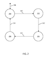
- FIG. 2 shows exemplary values or states of a signaling flag for use in a handshake protocol according to an embodiment of the invention.
- a method which enables a user to interact with a device (i.e. a controlled device) which does not comprise user interaction means, or which only comprises minimal user interaction means.
- the method involves a second device (i.e. a user interaction device) which may comprise rich user interaction means.
- FIG. 1 illustrates exemplary embodiments of a controlled device 100 and a user interaction device 120 according to the invention. Effectively, the controlled device 100 and the user interaction device 120 form a system in which the above-mentioned method can be applied.
- the controlled device 100 comprises a host controller 112 and a so-called Connected Tag 102 .
- a “Connected Tag” is defined as an RFID tag which has a host connection 116 , i.e. a wired connection, to the host controller 112 .
- the Connected Tag 102 comprises a non-volatile memory 104 , a (passive) RFID interface 106 for contactless reading/writing of the non-volatile memory 104 , a tag controller 108 for controlling the functions of the tag and a wired interface 116 with the host controller 112 (i.e. the host connection) enabling the reading/writing of the non-volatile memory 104 by that host controller 112 .
- the controlled device 100 may for example be an energy-frugal sensor node, a household appliance such as a washing machine or a kitchen oven, a time-controlled electric plug or an electronic watch.
- the user interaction device 120 comprises an NFC interface device or an active RFID device 122 .
- the NFC interface device or active RFID device 122 is able to read/write data from/to the Connected Tag 102 , while supplying power to the Connected Tag 102 .
- the user interaction device 120 may, for example, be an NFC-enabled smart phone or a web tablet with a touch screen as user interaction means.
- the host controller 112 of the controlled device 100 writes certain operational parameters initially or regularly into the non-volatile memory 104 of the Connected Tag 102 .
- the end-user interacts with a user interface 126 comprised in the user interaction device 120 , which results in new and/or updated operational parameters for the controlled device 100 .
- step (1) it is not necessary for step (1) to be immediately followed by steps (2), (3) and (4). Likewise, it is not necessary for steps (2), (3) and (4) to be immediately followed by step (5). In other words, there may be an unspecified time lag between the execution of step (1) on one hand and steps (2), (3) and (4) on the other hand. Similarly, there may be an unspecified time lag between steps (2), (3) and (4) on one hand and step (5) on the other hand. Furthermore, it is possible for step (1) to be executed multiple times, before executing steps (2), (3) and (4) or for steps (2), (3) and (4) to be executed multiple times without step (1) being executed in between. Similarly, it is possible for steps (2), (3) and (4) to be executed multiple times before executing step (5) once.
- non-volatile memory 104 instead of the non-volatile memory 104 another type of memory may be implemented on the Connected Tag 102 . However, it is important that the contents of the memory can be retained when no external power is supplied to the Connected Tag 102 . In particular, the new and/or updated operational parameters should remain available to the host controller 112 after disappearance of the RF field, so that the host controller 112 may perform step (5) at any time. In principle this may also be achieved with a volatile memory and a battery backup.
- the controlled device 100 does not have to be equipped with rich user interaction means, while it still enables rich user interaction via the user interaction device 120 .
- the controlled device 100 has no room for a touch screen or is used in a harsh environment where the touch screen may get dirty or even be destroyed.
- the controlled device 100 may be completely stripped of any user interaction means, which further lowers its cost and further increases its design freedom.
- an energy-frugal sensor node according to an embodiment of the invention requires no buttons or LED's at all (it is even conceivable to completely mold it in Perspex, making it very robust against dirt and other environmental influences).
- a household appliance or time-controlled electric plug requires neither buttons nor a display and an electronic watch may require fewer buttons.
- the above-described method lowers cost (a Connected Tag 102 is very cost effective), simplifies session setup (the user interaction device 120 may simply be held close to the controlled device 100 ) and may even support interaction with the controlled device 100 whilst the latter is powered down. Furthermore, the energy needed by the controlled device 100 to accomplish the user interaction may be significantly lower as it needs to power neither user interaction means nor a radio for wireless communications. This is important if the controlled device 100 is significantly more energy-constrained than the user interaction device 120 , for example, when a smart phone is used to configure an energy-frugal sensor node.
- UI remote user interface
- the controlled device 100 also comprises a host memory 110 used by the host controller 112 and a set of controlled functions 114 .
- the controlled functions 114 embody any of the primary functions of the controlled device 100 , for example: sensors and storage and/or data transmission means in an energy-frugal sensor node, motors, heaters and valves in a washing machine, heating elements, fans and a microwave tube in a kitchen oven, relay and timing functions in a time-controlled electric plug, or timing functions in an electronic watch.
- the host controller 112 controls these functions 114 in accordance with the operational parameters.
- the user interaction device 120 comprises a controller 124 , a memory 128 , and a user interface 126 (i.e. user interaction means).
- the controller 124 may execute a program element which implements particular steps of the method, i.e. steps (2), (3), and (4)) and utilizes the memory 128 , the user interface 126 , and the NFC interface device or active RFID device 122 for this purpose.
- a wake-up signal 118 may be provided. For example, upon interaction of the NFC interface device or active RFID device 122 with the RFID interface 106 —e.g. to read from or write to the non-volatile memory 104 in general or from or to specific parts thereof—the wake-up signal 118 is raised by the Connected Tag 102 to wake up the host controller 112 from an off state or low-power state.
- the controlled device for use in this method may be an energy-frugal sensor node, a hearing aid, a household appliance, and a time-controlled electric plug or socket.
- An energy-frugal sensor node is a device that measures one or more physical quantities, for example, lighting level, temperature, air pressure, air flow, motion and concentrations of gases like relative humidity, CO 2 , CO, O 2 , ethylene and volatile organic compounds. It comprises means to store and/or wirelessly transmit these measurements for further usage.
- An energy-frugal sensor node typically operates in a duty-cycled fashion, i.e. waking up periodically from a very low power sleep mode for a very short period of time to perform and store/transmit some measurements and subsequently reverting back to the sleep mode.
- This duty-cycled operation makes the sensor node so energy-efficient that it can live on a small battery for many years or can even harvest its energy from the ambient.
- an energy-frugal sensor node is a data logging device for monitoring the quality of perishable products (e.g. food or medicine).
- the device is attached to a pallet of products or even to an individual product (e.g. a milk carton) and logs the environmental conditions during distribution or even during the entire lifetime of the product. Inspection of the logs can be used to assess the quality of the product (e.g. remaining shelf life).
- cost, power, and form factor constraints are so strict that the device cannot comprise rich (or even any) user interaction means.
- Using a low-cost Connected Tag of the kind set forth enables a rich user interaction on a user interaction device instead (even while the device is asleep or its battery is depleted).
- the user interaction could, for example, involve browsing the logged data, resetting the logged data when attaching the device to another pallet and modifying configuration settings such as the periodicity, the set of physical quantities to measure and the associated measurement accuracies.
- an in-body implant such as an intraocular implant or a subcutaneous implant that monitors and logs biologically relevant parameters in a human or an animal. Power and form factor constraints are extremely strict and external self-powered user interaction is probably the only possibility to read out and configure the implant.
- an energy-frugal sensor node is a wireless sensor node applied in, for example, a building control system or for structural integrity monitoring of constructions such as bridges.
- the measurements are transmitted periodically over a wireless network interface.
- the wireless network interface provides, in principle, means to remotely interrogate and configure the device, this may be difficult in practice.
- the device In order to be sensitive to interrogation and configuration requests (e.g. read out the current sensor values, set the periodicity or set the set of physical quantities and associated accuracies) the device must be in receive-mode permanently or at least at well agreed moments in time. When the device is in receive-mode frequently, its energy reserves may be depleted quickly. When the device is in receive-mode very infrequently the interaction may have very long response times.
- interaction by means of a method of the kind set forth enables low power usage while maintaining short response times.
- the wireless network interface may not be usable at all before the device is configured (i.e. chicken-and-egg problem).
- this device is one of a plurality of similar devices connected to the wireless network, a method of the kind set forth enables very intuitive selection of this particular device—as opposed to another device in the plurality—for subsequent user interaction by merely bringing the user interaction device in its proximity.
- a small form factor device is a hearing aid. It needs to fit in/on the auricle and, for aesthetic reasons, be as small as possible, meaning that there is no room on the device itself for rich user interaction means.
- a wide variety of audio parameters e.g. amplification per frequency band
- small adaptations to the settings may need to be made interactively. Providing rich user interaction by means of the method according to the invention enables the audiologist to do his job properly and efficiently, while the small form factor (i.e. aesthetics) constraints are still satisfied.
- the end-user of the hearing aid may need to change settings such as the volume or to enable a specific mode of operation such as “speech-mode”, “music-mode” or “TV-mode” (i.e. using an inductance loop to pick up the TV sound). Also that is easily accomplished with a method of the kind set forth: tap the phone to the ear (i.e. hearing aid), change the settings on the touch screen and tap it once again.
- Household appliances such as washing machines, tumble dryers, dish washers and kitchen ovens tend to get more and more integrated functionality. As user interaction means not always scale up with this increase in functionality, the end-user experience may suffer.
- a washing machine, tumble dryer or dish washer offers a wide variety of programs and may additionally have means to adapt its schedule to variable energy pricing schemes. This means complex user interaction may be required to use the appliance properly. Design constraints may seriously limit the amount of space available for providing user interaction means. For example, for aesthetic reasons, a dish washer may have to be hidden behind wood paneling. As a result, the user interaction means may end up on the top side of the door, that is only a few centimeters high. A touch screen at that location is clearly out of the question, not only for form factor reasons, but also considering the high temperatures and humidity it may be exposed to.
- the user interaction means are not accessible (or even visible) during operation of the dish washer, implying for example that the end-user is not kept informed about the progress of the dish washing process (e.g. time to completion).
- a method of the kind set forth provides a convenient way to interact with the household appliance and change its operational parameters.
- a high-end kitchen oven offers a wide variety of heating options (e.g. bottom heat, top heat, hot air, hot air for multiple layers, grill, microwave, steam, incineration cleaning and many combinations and intensity settings thereof), time functions, pre-programmed preparation schedules, etcetera.
- a kitchen oven has to fit a standard-sized kitchen cabinet.
- a so-called “compact” oven has to fit a 560 ⁇ 450 ⁇ 550 mm3 (w ⁇ h ⁇ d) cabinet. Within this form factor the actual oven cavity should have maximum dimensions to be able to prepare as much food as possible.
- a UI-less kitchen oven with a wide and high oven cavity could be provided that can be conveniently programmed by means of a rich user interaction device such as a smart phone or a web tablet.
- a time-controlled electric plug is a device that can switch mains powered loads on or off based on a pre-determined time schedule. Typically it can be inserted into an electric power outlet and it comprises an electric power outlet by itself to plug in the load.
- a partially randomized time schedule may be employed.
- it can be used to switch heating devices (such as an electric water boiler or a waterbed) on only when electricity is available at a low tariff.
- time-controlled electric plugs are available on the market either comprising a mechanical clock or an electronic clock.
- a mechanical clock it is programmed by means of putting pins in holes or by toggling mechanical levers.
- an electronic clock it is programmed by utilizing user interaction means, for example, a small LCD display and a handful of buttons.
- the programming of such a prior art time-controlled electric plug is often cumbersome. Having few buttons implies that very specific sequences of button presses are needed to accomplish a certain task. In many cases these sequences are not intuitive and also the result of the task cannot be easily verified, just adding to end-user frustration.
- the time-controlled electric plug comprises no user interaction means, but only a Connected Tag. This has a number of benefits:
- the cost of the plug can be lower, because the cost of a Connected Tag is much lower than the cost of above-mentioned user interaction means.
- the form factor of the plug can be much smaller as no room is needed for user interaction means; as a matter of fact the “plug” could be completely integrated into a wall socket.
- the user interaction device provides much richer user interaction means (e.g. touch screen) making the interaction more intuitive and better to verify, thereby reducing the probability of end-user frustration.
- user interaction means e.g. touch screen
- a method of the kind set forth also permits control over the controlled device 100 even while it is switched off. This is enabled by the fact that the Connected Tag 102 contains a non-volatile memory 104 and that the NFC interface device or active RFID device 122 comprised in the user interaction device 120 is able to power the interaction with the Connected Tag 102 . In this way, the controlled device 100 neither has to be switched on all the time, nor does the end-user have to switch it on explicitly before starting interaction (and switch it off again after completing interaction).
- step (1) of the method of the kind set forth is performed by the controlled device 100 at a moment that it is active (i.e. switched on), which may be different from the moment that user interaction takes place.
- the controlled device 100 might be switched off and actual user interaction, i.e. steps (2), (3), and (4), takes place.
- the controlled device 100 might be active again and take the changed operational parameters that resulted from this user interaction into account for its subsequent operation, i.e. the controlled device 100 performs step (5).
- a controlled device 100 it might be undesirable for a controlled device 100 to be switched on all the time, because its power consumption could increase significantly.
- an energy-frugal sensor node can only function if it only wakes up periodically for a very short period of time. This is known as duty-cycled operation.
- the controlled device 100 is an energy-frugal sensor node comprising one or more sensors and if its sensors' measurements can be displayed by means of the user interaction device 120 , the time lag between performing steps (1) and (2) may imply that the sensor values as displayed may be outdated.
- step (5) setting a timer controlled by the washing machine's host controller 112 —is not immediately triggered by the occurrence of step (4); writing the new programming into the Connected Tag 102 .
- the controlled device 100 is a device comprising a real-time clock—for example, a time-controlled electric plug or an electronic watch—and if the user interaction device 120 is used to set this clock to the correct time, the following might occur.
- the user interaction device 120 would read the ‘current’ time that was stored into the Connected Tag 102 by the controlled device 100 a certain amount of time before that as part of step (1).
- this time is not correct anymore and only confuses the end-user.
- a further exemplary embodiment of the invention which will be described in more detail below, enables steps (1) and (2) respectively (4) and (5) to follow each other instantaneously to avoid the drawbacks described above, while it is still neither necessary to keep the controlled device 100 powered all the time, nor to have the end-user switch it on and off manually.
- the optional wake-up signal 118 mentioned earlier plays a pivotal role in this exemplary embodiment and is briefly explained first.
- the basic principle of the wake-up signal 118 is as follows.
- the wake-up signal 118 is provided from the Connected Tag 102 to the host controller 112 of the controlled device 100 .
- the wake-up signal 118 is raised and the controlled device 100 is woken up from its off state or low-power state (i.e. the controlled device 100 is switched on).
- the wake-up signal is raised when the appearance—or the subsequent disappearance—of a field generated by an NFC interface device or active RFID device 122 is detected.
- the wake-up signal 118 is raised only when that NFC interface device or active RFID device 122 addresses this particular Connected Tag 102 , i.e. upon establishment of an RFID connection.
- the wake-up signal 118 is only raised when the non-volatile memory 104 —or predetermined memory cells thereof—have been written to or read from (or both) during the interaction.
- the raising of the wake-up signal 118 may be triggered by a general or a more specific event on the RFID connection 130 , e.g. the appearance or removal of an RF field (general event) or the reading from or writing to a specific memory cell (specific event).
- a general or a more specific event on the RFID connection 130 e.g. the appearance or removal of an RF field (general event) or the reading from or writing to a specific memory cell (specific event).
- the RFID tag sends a wake-up signal to the controlled device upon a predetermined event, such that the controlled device wakes up from an off state or low-power state.
- the predetermined event is a detection of an RF field by the RFID tag or the establishment of the RFID connection. This enables that the controlled device is able to perform step (1) substantially instantaneously before the user interaction device performs step (2).
- the predetermined event is the writing of the operational parameters to the RFID tag in step (4) or the disappearance of the RF field or the RFID connection in step (4). This enables that the controlled device is able to perform step (5) substantially instantaneously after step (4).
- FIG. 1 suggests that the wake-up signal 118 is fed to a pin of the host controller 112 causing it to wake up from an off state or low-power state.
- the power supply of the controlled device 100 is disabled or disconnected in the inactive state and the wake-up signal 118 pulls a switch, e.g. galvanic or MOSFET, to power the controlled device 100 to cause it to move to the active state.
- a switch e.g. galvanic or MOSFET
- a wake-up signal 118 from the Connected Tag 102 may also be beneficial if the controlled device 100 is not switched off or in a low-power state.
- the wake-up signal 118 simply serves as an interrupt signal to the host controller 112 , triggering it to start executing a subsequent step of the method.
- step (2) instantaneously follow step (1)
- the act of bringing the user interaction device 120 into close proximity of the controlled device 100 should trigger the host controller 112 to wake-up and provide the operational parameters to the Connected Tag 102 first (i.e. executing step (1)) before proceeding with step (2).
- step (5) instantaneously follow step (4)
- the writing of the changed operational parameters into the Connected Tag 102 by the user interaction device 120 should trigger the host controller 112 to wake up, read those operational parameters from the Connected Tag 102 and subsequently adapting its behavior based on these operational parameters (i.e. executing step (5)).
- a further exemplary embodiment of a method according to the invention, which exhibits those features, is described below.
- This method makes use of different types of wake-up signals, varying from very specific wake-up triggers (e.g. a specific memory cell of the Connected Tag 102 being written) to very generic wake-up triggers (e.g. an RF field or RFID connection 130 appearing or disappearing). It is noted that the disappearance of the RF field or the RFID connection 130 may be a very natural wake-up trigger for causing the transition from step (4) to step (5); the end-user is ready with the user interaction and removes the user interaction device 120 from the close proximity of the controlled device 100 , thereby removing the RF field and the RFID connection 130 .
- a handshake protocol is executed between the user interaction device 120 and the host controller 112 of the controlled device 100 via the Connected Tag 102 .
- a dedicated memory location i.e. a signaling flag—is allocated in the non-volatile memory 104 of the Connected Tag 102 .
- FIG. 2 shows exemplary values or states of a signaling flag for use in a handshake protocol according to an embodiment of the invention.
- this signaling flag may assume any of four values (states): “waiting for request” 200 , “request parameters” 202 , “parameters available” 204 and “parameters updated” 206 .
- the signaling flag is initialized with the value “waiting for request” 200 .
- the writing of the signaling flag by the user interaction device 120 should cause the wake-up signal 118 being raised by the Connected Tag 102 .
- other events e.g. writing to another memory location, not being the signaling flag or even the mere appearance or disappearance of a random RF field
- the wake-up signal 118 may be raised as well.
- the exemplary method described below is made robust against such “false hits” by having the host controller 112 check the value of the signaling flag before proceeding with its next step. Although these “false hits” do not break the exemplary method as presented, they may cause more frequent (and unnecessary) wake-ups of the host controller 112 , resulting in unnecessary power consumption.
- having the Connected Tag 102 support more specific wake-up triggers enables a reduced power consumption of the controlled device 100 . For an energy frugal sensor node, for example, this may be beneficial.
- a further exemplary embodiment of a method according to the invention comprises the following steps (it is noted that steps (1) and (5) of the above-described method are now split up in sub-steps):
- the end-user brings the user interaction device 120 into close proximity of the controlled device 100 and the user interaction device 120 changes the value of the signaling flag in the Connected Tag 102 from “waiting for request” 200 to “request parameters” 202 , resulting in a first state transition 210 .
- the Connected Tag 102 raises the wake-up signal 118 in response to this interaction with the Connected Tag 102 , the host controller 112 wakes up and checks whether the signaling flag is set to “request parameters” 202 . If so, the host controller 112 proceeds with the next step. If not, the host controller 112 may return to the off state or low-power state.
- the host controller 112 obtains or computes the operational parameters and subsequently writes them into (another memory location of) the non-volatile memory 104 . Subsequently, the host controller 112 sets the signaling flag to “parameters available” 204 , resulting in a second state transition 212 . (2) The user interaction device 120 polls the signaling flag until it is set to “parameters available” 204 and subsequently reads the operational parameters from the Connected Tag 102 . (3) The end-user interacts with a user interface 126 on the user interaction device 120 resulting in changed operational parameters (i.e. new and/or updated operational parameters) for the controlled device 100 .
- the end-user brings the user interaction device 120 again into close proximity of the controlled device 100 —alternatively, it is kept in close proximity during the whole procedure—and the user interaction device 120 writes the new and/or updated operational parameters into the Connected Tag 102 . Then, the user interaction device 120 sets the signaling flag to “parameters updated” 206 , resulting in a third state transition 214 .
- the Connected Tag 102 raises the wake-up signal 118 in response to this interaction with the Connected Tag 102 , the host controller 112 wakes up and checks whether the signaling flag is set to “parameters updated” 206 . If so, the host controller 112 proceeds with the next step.
- the host controller 112 may return to the off state or low-power state.
- the host controller 112 reads the new and/or updated operational parameters from the Connected Tag 102 and subsequently adapts its behavior based on these operational parameters. Finally, the host controller 112 sets the signaling flag to “waiting for request” 200 , resulting in a fourth state transition 216 .
- step (5a) the host controller 112 may check the signaling flag just before it is actually set to “parameters updated” 206 by the user interaction device 120 in step (4) and conclude that it does not have to proceed with step (5b).
- This race condition can be avoided by either the Connected Tag 102 delaying the raising of the wake-up signal 118 (e.g.
- the host controller 112 polling the signaling flag over a certain period of time (e.g. 100 ms). If the wake-up signal 118 is triggered by the disappearance of the RF field or the RFID connection or by the actual writing of the memory cell containing the signaling flag, then this race condition does not occur.
- steps (1) and (2) comprise the use of the signaling flag.
- the signaling flag may be two-valued.
- the Connected Tag 102 may provide a wake-up signal 118 only upon reading and/or writing operational parameters (i.e. sets of memory cells of non-volatile memory 104 ) relating to those operations that require waking up.
- operational parameters i.e. sets of memory cells of non-volatile memory 104
- the memory cell containing signaling flag is a prime candidate for providing a wake-up signal 118 when it is written to by the user interaction device 120 .
- This configurability can be achieved by the host processor 112 writing configuration parameters into a special area of the non-volatile memory 104 by means of the host connection 116 .
- this special area could contain bitmaps indicating which areas of the non-volatile memory 104 must cause a wake-up when addressed for reading and/or writing, and which areas must not cause a wake-up.
- Control logic in the Connected Tag 102 will interpret the configuration parameters to decide whether or not to trigger the wake-up signal 118 upon addressing a specific memory cell.
- the controlled device is a washing machine
- different settings can be programmed without wake-up, for example the temperature and the washing program.
- start program button is pushed on the user interaction device 120 —or when a timer is programmed to start the washing machine at a certain moment in time—a wake-up is necessary.
- the controlled device 100 is an energy-frugal sensor node it may not be necessary to wake it up when the operational parameters are typical configuration settings which need to be programmed into it—such as the set of physical quantities to measure and the associated measurement accuracies—or when the operational parameters consist of actual measurements of slowly changing physical phenomena which need to be checked—such as the room temperature. However, it may be necessary to wake it up when the operational parameters consist of measurements of quickly changing physical phenomena—such as a lighting level—or when it is enabled for duty-cycled operation for the first time.
- the operational parameters are typical configuration settings which need to be programmed into it—such as the set of physical quantities to measure and the associated measurement accuracies—or when the operational parameters consist of actual measurements of slowly changing physical phenomena which need to be checked—such as the room temperature.
- the operational parameters consist of measurements of quickly changing physical phenomena—such as a lighting level—or when it is enabled for duty-cycled operation for the first time.
- the energy-frugal sensor node wakes up periodically to perform measurements—and log the results thereof in the non-volatile memory 104 and/or transmit them over a wireless interface—and that the slowly changing phenomena show little change during a single period, whereas the quickly changing phenomena may show a lot of change during a single period.
- the operational parameters supplied by the controlled device 100 to the user interaction device 120 as part of step (2) of a method of the kind set forth may comprise a user interface description in addition to—or effectively embedding—operational parameters that directly relate to the functioning of the controlled device 100 .
- the latter are called function parameters in this section.
- an HTML-page containing the function parameters as (default settings for) e.g. radio button selectors, check boxes, and/or pull down menu controls may be provided as operational parameter.
- the user interaction device 120 will load this HTML-page into an HTML-renderer application enabling the end-user to modify the various controls (and hence the function parameters).
- the HTML-renderer application is very similar to an Internet browser, but the protocols to communicate with the Connected Tag 102 may be different from plain HTTP.
- the HTML-renderer application may be realized by means of a standard browser and an embedded web server that converts those protocols to/from HTTP. After the end-user has finished modifying the controls, the function parameters must be “posted” back to the controlled device 100 as part of step (4).
- This action of “posting” the function parameters can be triggered by a “submit” button on the HTML-page or, alternatively, by the end-user bringing the user interaction device 120 into close proximity of the controlled device 100 .
- the end-user needs to press the “submit” button while the user interaction device 120 is in close proximity of the controlled device 100 .
- a combination of the two is also possible: either the end-user pressing the “submit” button in close proximity, or the end-user first pressing the “submit” button and subsequently bringing the user interaction device 120 into close proximity again.
- the benefit of including a user interface description in the operational parameters is the ability to have a dedicated user interface 126 for each type of controlled device 100 .
- the user interaction device 120 requires no a priori knowledge of the controlled device 100 and yet is able to provide an optimally tailored user interface 126 for it to the end-user. In other words, it is not necessary to install a different “app” on the user interaction device 120 for each different type of controlled device 100 . Instead, a single generic (protocol-adapted) browser suffices, such that the browser may be standardized.
- the user interface 126 could also be branded by the manufacturer of the controlled device 100 .
- the user interface description may comprise client-executable code such as JavaScript, CSS, Java or Adobe Flash—stored as additional files on the Connected Tag 102 —offering a more dynamic (e.g. animated) user interface experience and/or the possibility to compute function parameters from more user-friendly settings.
- client-executable code such as JavaScript, CSS, Java or Adobe Flash—stored as additional files on the Connected Tag 102 —offering a more dynamic (e.g. animated) user interface experience and/or the possibility to compute function parameters from more user-friendly settings.
- a temperature setting on the user interface 126 for a washing machine may be in Celsius or Fahrenheit, while the parameters accepted by the washing machine are in yet another unit of measurement.
- the user interface description may be provided by reference, for example by the controlled device 100 providing a URL pointing to a user interface description—instead of the user interface description itself—as part of the operational parameters.
- the user interaction device 120 furthermore needs to comprise Internet access means, for example, a Wi-Fi radio or a GPRS/UMTS modem. This is typically the case when the user interaction device 120 is a smart phone or a web tablet.
- the user interaction device 120 uses the URL thus obtained to retrieve the actual user interface description utilizing the Internet access means and subsequently presents a user interface 126 in accordance with this description to the end-user (after which the method proceeds as outlined above).
- the non-volatile memory 104 of the Connected Tag 102 needs to provide less data (a URL typically being much smaller than a user interface description) reducing the cost of the controlled device 100 and possibly also the download time of the user interface description. As this effectively removes any size constraint on the user interface description, the user interface description could even be a dedicated application that is automatically downloaded and installed on the user interaction device 120 .
- the manufacturer of the controlled device 100 can easily update the user interface description by providing a new version on his website. It is noted that in this example it is assumed that the URL points to the website of the manufacturer.
- multiple message exchanges between the controlled device 100 and the user interaction device 120 may take place as part of a single user interaction session.
- the user interaction device 120 may go through steps (2), (3), and (4) of the method more than once and the controlled device 100 may be involved in steps (1), (2), (4) and (5) more than once.
- the user interface description may remain the same, or it may change (e.g. browse to new HTML-pages to obtain submenus). The point of this is that some state information (in this case a user interface description with actual settings for the function parameters) may be maintained by the user interaction device 120 while performing the method multiple times.
- the user interaction device 120 may cache the user interface description, so that it is not necessary to download it (from the controlled device 100 or from the Internet) each and every time that interaction with the controlled device 100 is needed.
- the user interaction device 120 Upon reading the operational parameters from the controlled device 100 , the user interaction device 120 obtains a unique identifier of the user interface description (in the variant above this is the URL) and checks whether it has already downloaded a user interface description with this unique identifier. Only if it has not, it will download the user interface description.
- a pin-code lock for, for example, a scooter.
- the user interaction device 120 obtains a user interface description from the scooter through the Connected Tag 102 .
- This user interface description supports the pin-code entry and writes the entered pin-code back into the Connected Tag 102 .
- the scooter is woken up by writing into the Connected Tag 102 (see section “Wake up host controller during or following interaction”). Subsequently, the scooter verifies the pin-code and releases the lock if the pin-code is correct.
- the user interface description is the only operational parameter read from the controlled device 100 (i.e. the scooter); no function parameters are read and only one function parameter is written (i.e. the pin-code).
- a more secure solution involves using a public/private key pair (i.e. public key cryptography).
- the smart phone first reads a user interface description and a public key from the scooter, in particular from its Connected Tag 102 , subsequently uses the user interface 126 to obtain the pin-code from the end-user, encrypts the pin-code with the public key and writes it back to the scooter, in particular to its Connected Tag 102 .
- the Connected Tag 102 wakes up the scooter, which first decrypts the pin-code with its private key. Subsequently the scooter verifies the pin-code, and if the pin-code is correct the scooter releases the lock.
- any reference sign placed between parentheses shall not be construed as limiting the claim.
- the word “comprise(s)” or “comprising” does not exclude the presence of elements or steps other than those listed in a claim.
- the word “a” or “an” preceding an element does not exclude the presence of a plurality of such elements.
- the invention may be implemented by means of hardware comprising several distinct elements and/or by means of a suitably programmed processor. In a device claim enumerating several means, several of these means may be embodied by one and the same item of hardware. The mere fact that certain measures are recited in mutually different dependent claims does not indicate that a combination of these measures cannot be used to advantage.
Landscapes
- Engineering & Computer Science (AREA)
- Physics & Mathematics (AREA)
- Theoretical Computer Science (AREA)
- General Physics & Mathematics (AREA)
- Microelectronics & Electronic Packaging (AREA)
- Computer Hardware Design (AREA)
- Artificial Intelligence (AREA)
- Computer Vision & Pattern Recognition (AREA)
- Health & Medical Sciences (AREA)
- Toxicology (AREA)
- Computer Networks & Wireless Communication (AREA)
- Electromagnetism (AREA)
- General Health & Medical Sciences (AREA)
- Selective Calling Equipment (AREA)
Abstract
Description
(5) The
(1b) The
(1c) The
(2) The
(3) The end-user interacts with a
(4) The end-user brings the
(5a) The
(5b) The
-
- When, reversely, it is not necessary for step (2) to instantaneously follow step (1), but it is necessary for step (5) to instantaneously follow step (4), only steps (4) and (5) comprise the use of the signaling flag. In this case the signaling flag may also be two-valued.
- Alternatively, the handshake mechanism (including the maintaining of its state as embodied by the signaling flag) may be realized in dedicated control hardware of the
Connected Tag 102. In this variant, theConnected Tag 102 provides the ability to intercept a read attempt of thenon-volatile memory 104 via itsRFID interface 106. When theuser interaction device 120 attempts to read operational parameters, theConnected Tag 102 stalls the response to theuser interaction device 120. In the mean time it wakes up thehost controller 112 by means of the wake-up signal 118, thehost controller 112 obtains or computes the operational parameters and subsequently writes them into thenon-volatile memory 104 at which point theConnected Tag 102 completes the read attempt by providing the requested operational parameters to theuser interaction device 120. As a matter of fact, intermediate storage of these operational parameters in thenon-volatile memory 104 is not even strictly necessary for this variant. Alternatively, the read attempt could be stalled by the dedicated control hardware of theConnected Tag 102 by a fixed amount of time, while the wake-up signal 118 is provided to thehost controller 112. This fixed amount of time should be sufficiently large for thehost controller 112 to wake-up, obtain or compute the operational parameters and write them into thenon-volatile memory 104. For example, the amount of time may be 100 ms. However, it should be noted that this variant is more complex, because theConnected Tag 102 is no longer a relatively simple dual-portednon-volatile memory 104—having anRFID interface 106 and ahost connection 116—with a wake-up capability, but a component which requires more complex control circuitry.
- 100 controlled device
- 102 RFID tag
- 104 non-volatile memory
- 106 RFID interface
- 108 tag controller
- 110 host memory
- 112 host controller
- 114 controlled functions
- 116 host connection
- 118 optional wake-up signal
- 120 user interaction device
- 122 NFC interface device or active RFID device
- 124 controller
- 126 user interface
- 128 memory
- 130 RFID connection
- 200 “waiting for request” state
- 202 “request parameters” state
- 204 “parameters available” state
- 206 “parameters updated” state
- 208 initialize
- 210 first state transition
- 212 second state transition
- 214 third state transition
- 216 fourth state transition
Claims (8)
Applications Claiming Priority (3)
| Application Number | Priority Date | Filing Date | Title |
|---|---|---|---|
| EP12163933.0 | 2012-04-12 | ||
| EP12163933 | 2012-04-12 | ||
| EP12163933.0A EP2650820B1 (en) | 2012-04-12 | 2012-04-12 | Control method and computer program product |
Publications (2)
| Publication Number | Publication Date |
|---|---|
| US20130271268A1 US20130271268A1 (en) | 2013-10-17 |
| US9514339B2 true US9514339B2 (en) | 2016-12-06 |
Family
ID=46044384
Family Applications (1)
| Application Number | Title | Priority Date | Filing Date |
|---|---|---|---|
| US13/862,316 Active 2034-08-13 US9514339B2 (en) | 2012-04-12 | 2013-04-12 | Control method, controlled device, user interaction device and computer program product |
Country Status (3)
| Country | Link |
|---|---|
| US (1) | US9514339B2 (en) |
| EP (1) | EP2650820B1 (en) |
| CN (1) | CN103377387B (en) |
Cited By (3)
| Publication number | Priority date | Publication date | Assignee | Title |
|---|---|---|---|---|
| US20160266843A1 (en) * | 2015-03-09 | 2016-09-15 | Kabushiki Kaisha Toshiba | Memory device, communication device, and memory controller |
| US10154018B2 (en) | 2015-02-19 | 2018-12-11 | Nxp B.V. | Method and system for facilitating network joining |
| US11461454B2 (en) | 2017-04-04 | 2022-10-04 | Analog Devices, Inc. | Passive sensor reader authentication protocol |
Families Citing this family (14)
| Publication number | Priority date | Publication date | Assignee | Title |
|---|---|---|---|---|
| EP2602677B1 (en) | 2011-12-05 | 2018-02-21 | Nxp B.V. | Localization method, computer program product and localization device |
| EP2624081B1 (en) | 2012-01-31 | 2018-01-10 | Nxp B.V. | Configuration method, configuration device, computer program product and control system |
| EP2665235B1 (en) | 2012-05-15 | 2016-01-06 | Nxp B.V. | Method for establishing secure communication between nodes in a network, network node, key manager, installation device and computer program product |
| EP2704365B1 (en) | 2012-08-31 | 2016-02-03 | Nxp B.V. | Method for establishing control relationships, configuration device, networked device and computer program product |
| EP2770804B1 (en) | 2013-02-26 | 2020-07-15 | Nxp B.V. | Lighting control method, computer program product and lighting control system |
| EP2860950B1 (en) * | 2013-10-11 | 2017-04-12 | Nxp B.V. | Transferring a descriptive web interface language code between two nearfield communication devices |
| WO2015113618A1 (en) * | 2014-01-31 | 2015-08-06 | Arcelik Anonim Sirketi | System and method of operating a household appliance having a limited function control interface |
| JP6544903B2 (en) * | 2014-09-19 | 2019-07-17 | ホーチキ株式会社 | Wireless disaster prevention system, sensor node and repeater node |
| EP3086585B1 (en) | 2015-04-23 | 2019-12-11 | Nxp B.V. | Method and system for securing data communicated in a network |
| DE102015225831A1 (en) * | 2015-12-17 | 2017-06-22 | Bender Gmbh & Co. Kg | Method for data transmission between a measuring device and a communication terminal with automatic processing of a machine-readable identification of the measuring device |
| DE102016210413A1 (en) | 2016-06-13 | 2017-12-14 | Zumtobel Lighting Gmbh | Decentralized logging of operating states of building technology components |
| US11086279B2 (en) * | 2017-07-31 | 2021-08-10 | Solaredge Technologies Ltd. | Method to prepare a power converter or other apparatus for configuration |
| DE112019006454T5 (en) | 2018-12-28 | 2021-11-04 | Sony Group Corporation | Communication device and communication method |
| EP3907711A1 (en) * | 2020-05-08 | 2021-11-10 | Carrier Corporation | Configurable alarm system component |
Citations (36)
| Publication number | Priority date | Publication date | Assignee | Title |
|---|---|---|---|---|
| US5565855A (en) | 1991-05-06 | 1996-10-15 | U.S. Philips Corporation | Building management system |
| US6174073B1 (en) | 1996-01-02 | 2001-01-16 | Bernard Regan | Radio frequency remote-controllable lighting system having plurality of lighting units |
| DE19940651A1 (en) | 1999-08-26 | 2001-03-08 | Deutsch Zentr Luft & Raumfahrt | Device for receiving and / or sending communication and / or navigation signals |
| US6229433B1 (en) | 1999-07-30 | 2001-05-08 | X-10 Ltd. | Appliance control |
| US20020170952A1 (en) | 2001-04-04 | 2002-11-21 | Koninklijke Philips Electronics N.V. | Internet enabled resource constrained terminal for processing tags |
| US20030137396A1 (en) | 2002-01-22 | 2003-07-24 | Durej Ronald G. | System and method for configuration of HVAC network |
| EP1479988A2 (en) | 2003-05-23 | 2004-11-24 | WRAP S.p.A. | Household appliance, particularly a refrigeration apparatus, with a control system using sensor means based on RFID technology |
| US20050093374A1 (en) | 2003-10-31 | 2005-05-05 | Timothy Connors | Controlling power supplied to a circuit using an externally applied magnetic field |
| WO2006016845A1 (en) | 2004-08-10 | 2006-02-16 | Tac Ab | Field device management |
| WO2006020152A1 (en) | 2004-07-27 | 2006-02-23 | Intel Corporation | Method and apparatus for accessing information on an external machine-readable tag |
| US20060049935A1 (en) | 2002-12-19 | 2006-03-09 | Koninklijke Philips Electronics N.V. | Method of configuration a wireless-controlled lighting system |
| CN1766903A (en) | 2004-10-27 | 2006-05-03 | 乐金电子(天津)电器有限公司 | Electric device for reading smart tag |
| US7174227B2 (en) | 2002-01-22 | 2007-02-06 | Kabushiki Kaisha Toshiba | Laundry system including home terminal device and laundry apparatus with communicating function |
| WO2007016101A1 (en) | 2005-07-29 | 2007-02-08 | Alcon, Inc. | Method and system for configuring and data populating a surgical device |
| US20070047749A1 (en) | 2005-08-31 | 2007-03-01 | Thomas Kasztelan | Hearing aid with transponder device and corresponding data transmission method |
| US20080048837A1 (en) | 2006-07-18 | 2008-02-28 | Hewlett-Packard Development Company Lp | RF tag |
| WO2008085423A1 (en) | 2007-01-03 | 2008-07-17 | Intelleflex Corporation | Long range rfid device as modem and systems implementing same |
| US20080204249A1 (en) | 2007-02-26 | 2008-08-28 | Kai-Cheng Chang | Radio frequency identification systems for electronic devices |
| US20080204199A1 (en) | 2007-01-22 | 2008-08-28 | Cisco Technology | Method And System For Remotely Provisioning And/Or Configuring A Device |
| US20080211427A1 (en) | 2005-06-02 | 2008-09-04 | Koninklijke Philips Electronics, N.V. | Lighting System and Method for Controlling a Lighting System |
| US20090009358A1 (en) | 2006-03-18 | 2009-01-08 | Demag Cranes & Components Gmbh | Method and system for wirelessly transmitting control commands for a controller for lifting gear |
| EP2050863A1 (en) | 2006-05-02 | 2009-04-22 | Electrolux Home Products Corporation N.V. | Household appliance with program status indicator |
| US20090121865A1 (en) | 2007-11-14 | 2009-05-14 | Hamel Andrew J | System and method for automatically powering on and synchronizing a wireless remote console to a central control unit so as to allow remote control of a medical device |
| WO2010032227A1 (en) | 2008-09-22 | 2010-03-25 | Nxp B.V. | Automatic address selection for controllable devices |
| US7825776B2 (en) | 2006-08-17 | 2010-11-02 | Intel Corporation | Device configuration with RFID |
| DE102006035011B4 (en) | 2006-07-28 | 2010-11-25 | Siemens Audiologische Technik Gmbh | Programming system for a hearing aid and method |
| CN101951335A (en) | 2010-09-29 | 2011-01-19 | 广州市聚晖电子科技有限公司 | System and method for realizing interconnection and interworking protocol stack between digital home network devices |
| WO2011057194A1 (en) | 2009-11-06 | 2011-05-12 | Skyhawke Technologies, Llc | Golf shot tracking system |
| US20110143661A1 (en) | 2007-11-30 | 2011-06-16 | Nokia Corporation | Method, device and system for firmware update by near-field communication |
| CN102324050A (en) | 2011-04-19 | 2012-01-18 | 佛山市瑞德软件科技有限公司 | Method and dedicated device for recording information of home appliance controller by using RFID (Radio Frequency Identification Device) chip |
| US20120133841A1 (en) * | 2010-11-30 | 2012-05-31 | Verizon Patent And Licensing, Inc. | Universal remote control systems, methods, and apparatuses |
| US20120176244A1 (en) * | 2011-01-07 | 2012-07-12 | Southern Imperial, Inc. | System and Method for Integrated Product Protection |
| US20130076491A1 (en) | 2011-09-23 | 2013-03-28 | Nx B.V. | System and method for commissioning devices |
| US20130141223A1 (en) | 2011-12-05 | 2013-06-06 | Nxp B.V. | Localization method, computer program product and localization device |
| US20130198813A1 (en) | 2012-01-31 | 2013-08-01 | Nxp B.V. | Configuration method, configuration device, computer program product and control system |
| US20130211761A1 (en) | 2012-02-10 | 2013-08-15 | Nxp B.V. | Calibration method, calibration device and measurement device |
-
2012
- 2012-04-12 EP EP12163933.0A patent/EP2650820B1/en active Active
-
2013
- 2013-04-03 CN CN201310115913.3A patent/CN103377387B/en active Active
- 2013-04-12 US US13/862,316 patent/US9514339B2/en active Active
Patent Citations (39)
| Publication number | Priority date | Publication date | Assignee | Title |
|---|---|---|---|---|
| US5565855A (en) | 1991-05-06 | 1996-10-15 | U.S. Philips Corporation | Building management system |
| US6174073B1 (en) | 1996-01-02 | 2001-01-16 | Bernard Regan | Radio frequency remote-controllable lighting system having plurality of lighting units |
| US6229433B1 (en) | 1999-07-30 | 2001-05-08 | X-10 Ltd. | Appliance control |
| DE19940651A1 (en) | 1999-08-26 | 2001-03-08 | Deutsch Zentr Luft & Raumfahrt | Device for receiving and / or sending communication and / or navigation signals |
| US20020170952A1 (en) | 2001-04-04 | 2002-11-21 | Koninklijke Philips Electronics N.V. | Internet enabled resource constrained terminal for processing tags |
| US7174227B2 (en) | 2002-01-22 | 2007-02-06 | Kabushiki Kaisha Toshiba | Laundry system including home terminal device and laundry apparatus with communicating function |
| US20030137396A1 (en) | 2002-01-22 | 2003-07-24 | Durej Ronald G. | System and method for configuration of HVAC network |
| US6667690B2 (en) | 2002-01-22 | 2003-12-23 | Carrier Corporation | System and method for configuration of HVAC network |
| US20060049935A1 (en) | 2002-12-19 | 2006-03-09 | Koninklijke Philips Electronics N.V. | Method of configuration a wireless-controlled lighting system |
| EP1479988A2 (en) | 2003-05-23 | 2004-11-24 | WRAP S.p.A. | Household appliance, particularly a refrigeration apparatus, with a control system using sensor means based on RFID technology |
| US20050093374A1 (en) | 2003-10-31 | 2005-05-05 | Timothy Connors | Controlling power supplied to a circuit using an externally applied magnetic field |
| US7250695B2 (en) * | 2003-10-31 | 2007-07-31 | Hewlett-Packard Development Company, L.P. | Controlling power supplied to a circuit using an externally applied magnetic field |
| WO2006020152A1 (en) | 2004-07-27 | 2006-02-23 | Intel Corporation | Method and apparatus for accessing information on an external machine-readable tag |
| WO2006016845A1 (en) | 2004-08-10 | 2006-02-16 | Tac Ab | Field device management |
| CN1766903A (en) | 2004-10-27 | 2006-05-03 | 乐金电子(天津)电器有限公司 | Electric device for reading smart tag |
| US20080211427A1 (en) | 2005-06-02 | 2008-09-04 | Koninklijke Philips Electronics, N.V. | Lighting System and Method for Controlling a Lighting System |
| WO2007016101A1 (en) | 2005-07-29 | 2007-02-08 | Alcon, Inc. | Method and system for configuring and data populating a surgical device |
| US20070047749A1 (en) | 2005-08-31 | 2007-03-01 | Thomas Kasztelan | Hearing aid with transponder device and corresponding data transmission method |
| US20090009358A1 (en) | 2006-03-18 | 2009-01-08 | Demag Cranes & Components Gmbh | Method and system for wirelessly transmitting control commands for a controller for lifting gear |
| EP2050863A1 (en) | 2006-05-02 | 2009-04-22 | Electrolux Home Products Corporation N.V. | Household appliance with program status indicator |
| US20080048837A1 (en) | 2006-07-18 | 2008-02-28 | Hewlett-Packard Development Company Lp | RF tag |
| DE102006035011B4 (en) | 2006-07-28 | 2010-11-25 | Siemens Audiologische Technik Gmbh | Programming system for a hearing aid and method |
| US7825776B2 (en) | 2006-08-17 | 2010-11-02 | Intel Corporation | Device configuration with RFID |
| WO2008085423A1 (en) | 2007-01-03 | 2008-07-17 | Intelleflex Corporation | Long range rfid device as modem and systems implementing same |
| US20080204199A1 (en) | 2007-01-22 | 2008-08-28 | Cisco Technology | Method And System For Remotely Provisioning And/Or Configuring A Device |
| US8098160B2 (en) * | 2007-01-22 | 2012-01-17 | Cisco Technology, Inc. | Method and system for remotely provisioning and/or configuring a device |
| US20080204249A1 (en) | 2007-02-26 | 2008-08-28 | Kai-Cheng Chang | Radio frequency identification systems for electronic devices |
| US20090121865A1 (en) | 2007-11-14 | 2009-05-14 | Hamel Andrew J | System and method for automatically powering on and synchronizing a wireless remote console to a central control unit so as to allow remote control of a medical device |
| US20110143661A1 (en) | 2007-11-30 | 2011-06-16 | Nokia Corporation | Method, device and system for firmware update by near-field communication |
| WO2010032227A1 (en) | 2008-09-22 | 2010-03-25 | Nxp B.V. | Automatic address selection for controllable devices |
| WO2011057194A1 (en) | 2009-11-06 | 2011-05-12 | Skyhawke Technologies, Llc | Golf shot tracking system |
| CN101951335A (en) | 2010-09-29 | 2011-01-19 | 广州市聚晖电子科技有限公司 | System and method for realizing interconnection and interworking protocol stack between digital home network devices |
| US20120133841A1 (en) * | 2010-11-30 | 2012-05-31 | Verizon Patent And Licensing, Inc. | Universal remote control systems, methods, and apparatuses |
| US20120176244A1 (en) * | 2011-01-07 | 2012-07-12 | Southern Imperial, Inc. | System and Method for Integrated Product Protection |
| CN102324050A (en) | 2011-04-19 | 2012-01-18 | 佛山市瑞德软件科技有限公司 | Method and dedicated device for recording information of home appliance controller by using RFID (Radio Frequency Identification Device) chip |
| US20130076491A1 (en) | 2011-09-23 | 2013-03-28 | Nx B.V. | System and method for commissioning devices |
| US20130141223A1 (en) | 2011-12-05 | 2013-06-06 | Nxp B.V. | Localization method, computer program product and localization device |
| US20130198813A1 (en) | 2012-01-31 | 2013-08-01 | Nxp B.V. | Configuration method, configuration device, computer program product and control system |
| US20130211761A1 (en) | 2012-02-10 | 2013-08-15 | Nxp B.V. | Calibration method, calibration device and measurement device |
Non-Patent Citations (6)
| Title |
|---|
| "Remote Desktop Protocol", Microsoft, 5 pgs. retrieved from the internet at: http://msdn.microsoft.com/en-us/library/aa383015.aspx (2011). |
| "Remote UI Client and Server V 1.0", 1 pg, retrieved from the internet at: http://upnp.org/specs/rui/remoteui/ (Aug. 25, 2004). |
| "STMicroelectronics Facilitates Contactless Communication between Mobile Phones and Other Electronic Device", ST Electronics, 2 pgs, retrieved from the internet at: http://www.st.com/internet/com/press-release/t3102.jsp (Jan. 19, 2012). |
| "Virtual Network Computing", Wikipedia, 5 pgs, Apr. 10, 2013 retrieved from the internet at: http://en.wikipedia.org/wiki/Virtual-Network-Computing. |
| "Wi-Fi Protected Setup Specification-Version 1.0", 109 pgs, WiFi Alliance, retrieved from the internet at: https://login.wi-fi.org/login.php?resume=/idp/resumeSAML20/idp/SSO.ping&spentity=www.wi-fi.org (Sep. 2006). |
| Extended European Search Report for Patent Appln. 12163933.0 (Sep. 24, 2012). |
Cited By (3)
| Publication number | Priority date | Publication date | Assignee | Title |
|---|---|---|---|---|
| US10154018B2 (en) | 2015-02-19 | 2018-12-11 | Nxp B.V. | Method and system for facilitating network joining |
| US20160266843A1 (en) * | 2015-03-09 | 2016-09-15 | Kabushiki Kaisha Toshiba | Memory device, communication device, and memory controller |
| US11461454B2 (en) | 2017-04-04 | 2022-10-04 | Analog Devices, Inc. | Passive sensor reader authentication protocol |
Also Published As
| Publication number | Publication date |
|---|---|
| EP2650820B1 (en) | 2014-10-08 |
| CN103377387B (en) | 2016-04-06 |
| US20130271268A1 (en) | 2013-10-17 |
| EP2650820A1 (en) | 2013-10-16 |
| CN103377387A (en) | 2013-10-30 |
Similar Documents
| Publication | Publication Date | Title |
|---|---|---|
| US9514339B2 (en) | Control method, controlled device, user interaction device and computer program product | |
| US10386802B2 (en) | Home appliance and online system including the same | |
| US10633778B2 (en) | Home appliance and online system including the same | |
| CN109162063B (en) | Washing device and online system comprising same | |
| EP2704365B1 (en) | Method for establishing control relationships, configuration device, networked device and computer program product | |
| CN103718505A (en) | Laundry machine and online system including the same | |
| US8786412B2 (en) | Appliance network for a networked appliance and a remote user interface | |
| ITTO970017A1 (en) | CONTROL SYSTEM FOR A HOME APPLIANCE APPARATUS. | |
| KR100474930B1 (en) | Apparatus and method for monitoring history of goods in home network | |
| US8719407B2 (en) | Network device, information processing apparatus, control method of the same, and recording medium for the same | |
| KR20140077844A (en) | Method for activating a service mode in an electronic device and associated device | |
| KR20180019144A (en) | laundry machine and online system including the same | |
| JP7290735B2 (en) | Program push method and program execution method for home appliance | |
| CN110714296B (en) | Clothes treating device | |
| KR101830746B1 (en) | laundry machine and online system including the same | |
| CN109101182A (en) | A kind of touch control method and relevant apparatus | |
| KR20130013236A (en) | Laundry machine and online system including the same | |
| US20230055413A1 (en) | Method for operating a domestic appliance, computer program product and arrangement comprising a domestic appliance and an external operating device | |
| JP2021037025A (en) | Washing system and program | |
| KR20130014042A (en) | Laundry machine and online system including the same |
Legal Events
| Date | Code | Title | Description |
|---|---|---|---|
| AS | Assignment |
Owner name: MORGAN STANLEY SENIOR FUNDING, INC., MARYLAND Free format text: SECURITY AGREEMENT SUPPLEMENT;ASSIGNOR:NXP B.V.;REEL/FRAME:038017/0058 Effective date: 20160218 |
|
| AS | Assignment |
Owner name: NXP B.V., NETHERLANDS Free format text: ASSIGNMENT OF ASSIGNORS INTEREST;ASSIGNORS:BRANDSMA, EWOUT;VAN ROERMUND, TIMO;PENNINGS, MAARTEN CHRISTIAAN;REEL/FRAME:038111/0506 Effective date: 20121005 |
|
| AS | Assignment |
Owner name: MORGAN STANLEY SENIOR FUNDING, INC., MARYLAND Free format text: CORRECTIVE ASSIGNMENT TO CORRECT THE REMOVE APPLICATION 12092129 PREVIOUSLY RECORDED ON REEL 038017 FRAME 0058. ASSIGNOR(S) HEREBY CONFIRMS THE SECURITY AGREEMENT SUPPLEMENT;ASSIGNOR:NXP B.V.;REEL/FRAME:039361/0212 Effective date: 20160218 |
|
| STCF | Information on status: patent grant |
Free format text: PATENTED CASE |
|
| AS | Assignment |
Owner name: MORGAN STANLEY SENIOR FUNDING, INC., MARYLAND Free format text: CORRECTIVE ASSIGNMENT TO CORRECT THE REMOVE APPLICATION 12681366 PREVIOUSLY RECORDED ON REEL 039361 FRAME 0212. ASSIGNOR(S) HEREBY CONFIRMS THE SECURITY AGREEMENT SUPPLEMENT;ASSIGNOR:NXP B.V.;REEL/FRAME:042762/0145 Effective date: 20160218 Owner name: MORGAN STANLEY SENIOR FUNDING, INC., MARYLAND Free format text: CORRECTIVE ASSIGNMENT TO CORRECT THE REMOVE APPLICATION 12681366 PREVIOUSLY RECORDED ON REEL 038017 FRAME 0058. ASSIGNOR(S) HEREBY CONFIRMS THE SECURITY AGREEMENT SUPPLEMENT;ASSIGNOR:NXP B.V.;REEL/FRAME:042985/0001 Effective date: 20160218 |
|
| AS | Assignment |
Owner name: NXP B.V., NETHERLANDS Free format text: RELEASE BY SECURED PARTY;ASSIGNOR:MORGAN STANLEY SENIOR FUNDING, INC.;REEL/FRAME:050745/0001 Effective date: 20190903 |
|
| AS | Assignment |
Owner name: MORGAN STANLEY SENIOR FUNDING, INC., MARYLAND Free format text: CORRECTIVE ASSIGNMENT TO CORRECT THE REMOVE APPLICATION 12298143 PREVIOUSLY RECORDED ON REEL 042762 FRAME 0145. ASSIGNOR(S) HEREBY CONFIRMS THE SECURITY AGREEMENT SUPPLEMENT;ASSIGNOR:NXP B.V.;REEL/FRAME:051145/0184 Effective date: 20160218 Owner name: MORGAN STANLEY SENIOR FUNDING, INC., MARYLAND Free format text: CORRECTIVE ASSIGNMENT TO CORRECT THE REMOVE APPLICATION 12298143 PREVIOUSLY RECORDED ON REEL 039361 FRAME 0212. ASSIGNOR(S) HEREBY CONFIRMS THE SECURITY AGREEMENT SUPPLEMENT;ASSIGNOR:NXP B.V.;REEL/FRAME:051029/0387 Effective date: 20160218 Owner name: MORGAN STANLEY SENIOR FUNDING, INC., MARYLAND Free format text: CORRECTIVE ASSIGNMENT TO CORRECT THE REMOVE APPLICATION 12298143 PREVIOUSLY RECORDED ON REEL 042985 FRAME 0001. ASSIGNOR(S) HEREBY CONFIRMS THE SECURITY AGREEMENT SUPPLEMENT;ASSIGNOR:NXP B.V.;REEL/FRAME:051029/0001 Effective date: 20160218 Owner name: MORGAN STANLEY SENIOR FUNDING, INC., MARYLAND Free format text: CORRECTIVE ASSIGNMENT TO CORRECT THE REMOVE APPLICATION12298143 PREVIOUSLY RECORDED ON REEL 042985 FRAME 0001. ASSIGNOR(S) HEREBY CONFIRMS THE SECURITY AGREEMENT SUPPLEMENT;ASSIGNOR:NXP B.V.;REEL/FRAME:051029/0001 Effective date: 20160218 Owner name: MORGAN STANLEY SENIOR FUNDING, INC., MARYLAND Free format text: CORRECTIVE ASSIGNMENT TO CORRECT THE REMOVE APPLICATION12298143 PREVIOUSLY RECORDED ON REEL 039361 FRAME 0212. ASSIGNOR(S) HEREBY CONFIRMS THE SECURITY AGREEMENT SUPPLEMENT;ASSIGNOR:NXP B.V.;REEL/FRAME:051029/0387 Effective date: 20160218 Owner name: MORGAN STANLEY SENIOR FUNDING, INC., MARYLAND Free format text: CORRECTIVE ASSIGNMENT TO CORRECT THE REMOVE APPLICATION 12298143 PREVIOUSLY RECORDED ON REEL 038017 FRAME 0058. ASSIGNOR(S) HEREBY CONFIRMS THE SECURITY AGREEMENT SUPPLEMENT;ASSIGNOR:NXP B.V.;REEL/FRAME:051030/0001 Effective date: 20160218 Owner name: MORGAN STANLEY SENIOR FUNDING, INC., MARYLAND Free format text: CORRECTIVE ASSIGNMENT TO CORRECT THE REMOVE APPLICATION12298143 PREVIOUSLY RECORDED ON REEL 042762 FRAME 0145. ASSIGNOR(S) HEREBY CONFIRMS THE SECURITY AGREEMENT SUPPLEMENT;ASSIGNOR:NXP B.V.;REEL/FRAME:051145/0184 Effective date: 20160218 |
|
| MAFP | Maintenance fee payment |
Free format text: PAYMENT OF MAINTENANCE FEE, 4TH YEAR, LARGE ENTITY (ORIGINAL EVENT CODE: M1551); ENTITY STATUS OF PATENT OWNER: LARGE ENTITY Year of fee payment: 4 |
|
| MAFP | Maintenance fee payment |
Free format text: PAYMENT OF MAINTENANCE FEE, 8TH YEAR, LARGE ENTITY (ORIGINAL EVENT CODE: M1552); ENTITY STATUS OF PATENT OWNER: LARGE ENTITY Year of fee payment: 8 |