US9409574B2 - Vehicle acceleration suppression device and vehicle acceleration suppression method - Google Patents
Vehicle acceleration suppression device and vehicle acceleration suppression method Download PDFInfo
- Publication number
- US9409574B2 US9409574B2 US14/441,239 US201314441239A US9409574B2 US 9409574 B2 US9409574 B2 US 9409574B2 US 201314441239 A US201314441239 A US 201314441239A US 9409574 B2 US9409574 B2 US 9409574B2
- Authority
- US
- United States
- Prior art keywords
- obstacle
- vehicle
- distance
- acceleration suppression
- decision level
- Prior art date
- Legal status (The legal status is an assumption and is not a legal conclusion. Google has not performed a legal analysis and makes no representation as to the accuracy of the status listed.)
- Active
Links
- 230000001133 acceleration Effects 0.000 title claims abstract description 203
- 230000001629 suppression Effects 0.000 title claims abstract description 174
- 238000000034 method Methods 0.000 title claims abstract description 44
- 238000001514 detection method Methods 0.000 claims abstract description 99
- 238000013459 approach Methods 0.000 claims abstract description 29
- 239000004575 stone Substances 0.000 claims abstract description 28
- 230000005540 biological transmission Effects 0.000 claims description 41
- 230000003213 activating effect Effects 0.000 abstract description 9
- 230000004913 activation Effects 0.000 description 66
- 230000008569 process Effects 0.000 description 25
- 244000025254 Cannabis sativa Species 0.000 description 9
- 238000005070 sampling Methods 0.000 description 5
- 230000000694 effects Effects 0.000 description 3
- 239000012530 fluid Substances 0.000 description 3
- 230000000452 restraining effect Effects 0.000 description 3
- 230000008859 change Effects 0.000 description 2
- 230000009471 action Effects 0.000 description 1
- 230000003247 decreasing effect Effects 0.000 description 1
- 238000005516 engineering process Methods 0.000 description 1
- 238000012986 modification Methods 0.000 description 1
- 230000004048 modification Effects 0.000 description 1
- 230000007935 neutral effect Effects 0.000 description 1
- 230000002093 peripheral effect Effects 0.000 description 1
- 230000004044 response Effects 0.000 description 1
- 230000035945 sensitivity Effects 0.000 description 1
- 239000007787 solid Substances 0.000 description 1
Images


Classifications
-
- B—PERFORMING OPERATIONS; TRANSPORTING
- B60—VEHICLES IN GENERAL
- B60W—CONJOINT CONTROL OF VEHICLE SUB-UNITS OF DIFFERENT TYPE OR DIFFERENT FUNCTION; CONTROL SYSTEMS SPECIALLY ADAPTED FOR HYBRID VEHICLES; ROAD VEHICLE DRIVE CONTROL SYSTEMS FOR PURPOSES NOT RELATED TO THE CONTROL OF A PARTICULAR SUB-UNIT
- B60W50/00—Details of control systems for road vehicle drive control not related to the control of a particular sub-unit, e.g. process diagnostic or vehicle driver interfaces
- B60W50/08—Interaction between the driver and the control system
- B60W50/087—Interaction between the driver and the control system where the control system corrects or modifies a request from the driver
-
- B—PERFORMING OPERATIONS; TRANSPORTING
- B60—VEHICLES IN GENERAL
- B60T—VEHICLE BRAKE CONTROL SYSTEMS OR PARTS THEREOF; BRAKE CONTROL SYSTEMS OR PARTS THEREOF, IN GENERAL; ARRANGEMENT OF BRAKING ELEMENTS ON VEHICLES IN GENERAL; PORTABLE DEVICES FOR PREVENTING UNWANTED MOVEMENT OF VEHICLES; VEHICLE MODIFICATIONS TO FACILITATE COOLING OF BRAKES
- B60T7/00—Brake-action initiating means
- B60T7/12—Brake-action initiating means for automatic initiation; for initiation not subject to will of driver or passenger
- B60T7/22—Brake-action initiating means for automatic initiation; for initiation not subject to will of driver or passenger initiated by contact of vehicle, e.g. bumper, with an external object, e.g. another vehicle, or by means of contactless obstacle detectors mounted on the vehicle
-
- B—PERFORMING OPERATIONS; TRANSPORTING
- B60—VEHICLES IN GENERAL
- B60W—CONJOINT CONTROL OF VEHICLE SUB-UNITS OF DIFFERENT TYPE OR DIFFERENT FUNCTION; CONTROL SYSTEMS SPECIALLY ADAPTED FOR HYBRID VEHICLES; ROAD VEHICLE DRIVE CONTROL SYSTEMS FOR PURPOSES NOT RELATED TO THE CONTROL OF A PARTICULAR SUB-UNIT
- B60W10/00—Conjoint control of vehicle sub-units of different type or different function
- B60W10/04—Conjoint control of vehicle sub-units of different type or different function including control of propulsion units
-
- B—PERFORMING OPERATIONS; TRANSPORTING
- B60—VEHICLES IN GENERAL
- B60W—CONJOINT CONTROL OF VEHICLE SUB-UNITS OF DIFFERENT TYPE OR DIFFERENT FUNCTION; CONTROL SYSTEMS SPECIALLY ADAPTED FOR HYBRID VEHICLES; ROAD VEHICLE DRIVE CONTROL SYSTEMS FOR PURPOSES NOT RELATED TO THE CONTROL OF A PARTICULAR SUB-UNIT
- B60W10/00—Conjoint control of vehicle sub-units of different type or different function
- B60W10/18—Conjoint control of vehicle sub-units of different type or different function including control of braking systems
-
- B—PERFORMING OPERATIONS; TRANSPORTING
- B60—VEHICLES IN GENERAL
- B60W—CONJOINT CONTROL OF VEHICLE SUB-UNITS OF DIFFERENT TYPE OR DIFFERENT FUNCTION; CONTROL SYSTEMS SPECIALLY ADAPTED FOR HYBRID VEHICLES; ROAD VEHICLE DRIVE CONTROL SYSTEMS FOR PURPOSES NOT RELATED TO THE CONTROL OF A PARTICULAR SUB-UNIT
- B60W30/00—Purposes of road vehicle drive control systems not related to the control of a particular sub-unit, e.g. of systems using conjoint control of vehicle sub-units
- B60W30/08—Active safety systems predicting or avoiding probable or impending collision or attempting to minimise its consequences
- B60W30/09—Taking automatic action to avoid collision, e.g. braking and steering
-
- G—PHYSICS
- G01—MEASURING; TESTING
- G01S—RADIO DIRECTION-FINDING; RADIO NAVIGATION; DETERMINING DISTANCE OR VELOCITY BY USE OF RADIO WAVES; LOCATING OR PRESENCE-DETECTING BY USE OF THE REFLECTION OR RERADIATION OF RADIO WAVES; ANALOGOUS ARRANGEMENTS USING OTHER WAVES
- G01S15/00—Systems using the reflection or reradiation of acoustic waves, e.g. sonar systems
- G01S15/02—Systems using the reflection or reradiation of acoustic waves, e.g. sonar systems using reflection of acoustic waves
- G01S15/06—Systems determining the position data of a target
- G01S15/46—Indirect determination of position data
-
- G—PHYSICS
- G01—MEASURING; TESTING
- G01S—RADIO DIRECTION-FINDING; RADIO NAVIGATION; DETERMINING DISTANCE OR VELOCITY BY USE OF RADIO WAVES; LOCATING OR PRESENCE-DETECTING BY USE OF THE REFLECTION OR RERADIATION OF RADIO WAVES; ANALOGOUS ARRANGEMENTS USING OTHER WAVES
- G01S15/00—Systems using the reflection or reradiation of acoustic waves, e.g. sonar systems
- G01S15/87—Combinations of sonar systems
- G01S15/876—Combination of several spaced transmitters or receivers of known location for determining the position of a transponder or a reflector
- G01S15/878—Combination of several spaced transmitters or receivers of known location for determining the position of a transponder or a reflector wherein transceivers are operated, either sequentially or simultaneously, both in bi-static and in mono-static mode, e.g. cross-echo mode
-
- G—PHYSICS
- G01—MEASURING; TESTING
- G01S—RADIO DIRECTION-FINDING; RADIO NAVIGATION; DETERMINING DISTANCE OR VELOCITY BY USE OF RADIO WAVES; LOCATING OR PRESENCE-DETECTING BY USE OF THE REFLECTION OR RERADIATION OF RADIO WAVES; ANALOGOUS ARRANGEMENTS USING OTHER WAVES
- G01S15/00—Systems using the reflection or reradiation of acoustic waves, e.g. sonar systems
- G01S15/88—Sonar systems specially adapted for specific applications
- G01S15/93—Sonar systems specially adapted for specific applications for anti-collision purposes
- G01S15/931—Sonar systems specially adapted for specific applications for anti-collision purposes of land vehicles
-
- G—PHYSICS
- G01—MEASURING; TESTING
- G01S—RADIO DIRECTION-FINDING; RADIO NAVIGATION; DETERMINING DISTANCE OR VELOCITY BY USE OF RADIO WAVES; LOCATING OR PRESENCE-DETECTING BY USE OF THE REFLECTION OR RERADIATION OF RADIO WAVES; ANALOGOUS ARRANGEMENTS USING OTHER WAVES
- G01S7/00—Details of systems according to groups G01S13/00, G01S15/00, G01S17/00
- G01S7/52—Details of systems according to groups G01S13/00, G01S15/00, G01S17/00 of systems according to group G01S15/00
- G01S7/539—Details of systems according to groups G01S13/00, G01S15/00, G01S17/00 of systems according to group G01S15/00 using analysis of echo signal for target characterisation; Target signature; Target cross-section
-
- B—PERFORMING OPERATIONS; TRANSPORTING
- B60—VEHICLES IN GENERAL
- B60T—VEHICLE BRAKE CONTROL SYSTEMS OR PARTS THEREOF; BRAKE CONTROL SYSTEMS OR PARTS THEREOF, IN GENERAL; ARRANGEMENT OF BRAKING ELEMENTS ON VEHICLES IN GENERAL; PORTABLE DEVICES FOR PREVENTING UNWANTED MOVEMENT OF VEHICLES; VEHICLE MODIFICATIONS TO FACILITATE COOLING OF BRAKES
- B60T2201/00—Particular use of vehicle brake systems; Special systems using also the brakes; Special software modules within the brake system controller
- B60T2201/02—Active or adaptive cruise control system; Distance control
- B60T2201/022—Collision avoidance systems
-
- B—PERFORMING OPERATIONS; TRANSPORTING
- B60—VEHICLES IN GENERAL
- B60W—CONJOINT CONTROL OF VEHICLE SUB-UNITS OF DIFFERENT TYPE OR DIFFERENT FUNCTION; CONTROL SYSTEMS SPECIALLY ADAPTED FOR HYBRID VEHICLES; ROAD VEHICLE DRIVE CONTROL SYSTEMS FOR PURPOSES NOT RELATED TO THE CONTROL OF A PARTICULAR SUB-UNIT
- B60W2420/00—Indexing codes relating to the type of sensors based on the principle of their operation
- B60W2420/54—Audio sensitive means, e.g. ultrasound
-
- B—PERFORMING OPERATIONS; TRANSPORTING
- B60—VEHICLES IN GENERAL
- B60W—CONJOINT CONTROL OF VEHICLE SUB-UNITS OF DIFFERENT TYPE OR DIFFERENT FUNCTION; CONTROL SYSTEMS SPECIALLY ADAPTED FOR HYBRID VEHICLES; ROAD VEHICLE DRIVE CONTROL SYSTEMS FOR PURPOSES NOT RELATED TO THE CONTROL OF A PARTICULAR SUB-UNIT
- B60W2520/00—Input parameters relating to overall vehicle dynamics
- B60W2520/10—Longitudinal speed
-
- B—PERFORMING OPERATIONS; TRANSPORTING
- B60—VEHICLES IN GENERAL
- B60W—CONJOINT CONTROL OF VEHICLE SUB-UNITS OF DIFFERENT TYPE OR DIFFERENT FUNCTION; CONTROL SYSTEMS SPECIALLY ADAPTED FOR HYBRID VEHICLES; ROAD VEHICLE DRIVE CONTROL SYSTEMS FOR PURPOSES NOT RELATED TO THE CONTROL OF A PARTICULAR SUB-UNIT
- B60W2540/00—Input parameters relating to occupants
- B60W2540/10—Accelerator pedal position
-
- B60W2550/10—
-
- B—PERFORMING OPERATIONS; TRANSPORTING
- B60—VEHICLES IN GENERAL
- B60W—CONJOINT CONTROL OF VEHICLE SUB-UNITS OF DIFFERENT TYPE OR DIFFERENT FUNCTION; CONTROL SYSTEMS SPECIALLY ADAPTED FOR HYBRID VEHICLES; ROAD VEHICLE DRIVE CONTROL SYSTEMS FOR PURPOSES NOT RELATED TO THE CONTROL OF A PARTICULAR SUB-UNIT
- B60W2554/00—Input parameters relating to objects
-
- B—PERFORMING OPERATIONS; TRANSPORTING
- B60—VEHICLES IN GENERAL
- B60W—CONJOINT CONTROL OF VEHICLE SUB-UNITS OF DIFFERENT TYPE OR DIFFERENT FUNCTION; CONTROL SYSTEMS SPECIALLY ADAPTED FOR HYBRID VEHICLES; ROAD VEHICLE DRIVE CONTROL SYSTEMS FOR PURPOSES NOT RELATED TO THE CONTROL OF A PARTICULAR SUB-UNIT
- B60W2720/00—Output or target parameters relating to overall vehicle dynamics
- B60W2720/10—Longitudinal speed
- B60W2720/106—Longitudinal acceleration
-
- B—PERFORMING OPERATIONS; TRANSPORTING
- B60—VEHICLES IN GENERAL
- B60W—CONJOINT CONTROL OF VEHICLE SUB-UNITS OF DIFFERENT TYPE OR DIFFERENT FUNCTION; CONTROL SYSTEMS SPECIALLY ADAPTED FOR HYBRID VEHICLES; ROAD VEHICLE DRIVE CONTROL SYSTEMS FOR PURPOSES NOT RELATED TO THE CONTROL OF A PARTICULAR SUB-UNIT
- B60W30/00—Purposes of road vehicle drive control systems not related to the control of a particular sub-unit, e.g. of systems using conjoint control of vehicle sub-units
- B60W30/06—Automatic manoeuvring for parking
-
- G—PHYSICS
- G01—MEASURING; TESTING
- G01S—RADIO DIRECTION-FINDING; RADIO NAVIGATION; DETERMINING DISTANCE OR VELOCITY BY USE OF RADIO WAVES; LOCATING OR PRESENCE-DETECTING BY USE OF THE REFLECTION OR RERADIATION OF RADIO WAVES; ANALOGOUS ARRANGEMENTS USING OTHER WAVES
- G01S15/00—Systems using the reflection or reradiation of acoustic waves, e.g. sonar systems
- G01S15/88—Sonar systems specially adapted for specific applications
- G01S15/93—Sonar systems specially adapted for specific applications for anti-collision purposes
- G01S15/931—Sonar systems specially adapted for specific applications for anti-collision purposes of land vehicles
- G01S2015/937—Sonar systems specially adapted for specific applications for anti-collision purposes of land vehicles sensor installation details
- G01S2015/938—Sonar systems specially adapted for specific applications for anti-collision purposes of land vehicles sensor installation details in the bumper area
Definitions
- the present disclosure relates to a vehicle acceleration suppression device and a vehicle acceleration suppression method for performing acceleration suppression control as a drive assist to avoid an obstacle.
- JP 2010-164356 A for detecting an obstacle existing ahead in a travel direction of the vehicle.
- reflected waves of spherical surface transmission waves that have been emitted by an in-vehicle sonar are captured, so that the obstacle is detected.
- a threshold pattern for removing the reflected wave from the road surface is set and the threshold pattern is removed from the reflected wave that has been captured, so that the obstacle is detected.
- acceleration suppression control is performed as a drive assist for suppressing a contact between a vehicle and an obstacle such as a wall or another vehicle
- the acceleration suppression control is activated for the obstacles, such as a curb stone, edge stone, or grass (natural thing), for which the acceleration suppression is not needed, making a troublesome situation.
- the present disclosure intends to provide a vehicle acceleration suppression device and a vehicle acceleration suppression method, capable of activating the acceleration suppression control appropriately.
- an in-vehicle sonar configured to emit a transmission wave forward in a travel direction of a vehicle.
- An obstacle distance detector is configured to receive a reflection wave of the transmission wave emitted by the in-vehicle sonar, and to detect a distance between the vehicle and an obstacle existing ahead in the travel direction of the vehicle.
- An obstacle height determination unit is configured to receive the reflection wave of the transmission wave emitted by the in-vehicle sonar, and to determine whether or not the obstacle existing ahead in the travel direction of the vehicle is a tall obstacle that is as tall as the vehicle or taller than the vehicle.
- an obstacle type determination unit is configured to determine a type of the obstacle based on at least a first-time detection distance that is the distance between the vehicle and the obstacle detected by the obstacle distance detector for a first time, and a height determination distance that is the distance between the vehicle and the obstacle detected by the obstacle distance detector when the obstacle distance detector determines that the obstacle is the tall obstacle for the first time.
- an acceleration suppression controller is configured to carry out acceleration suppression control in a control manner depending on a determination result made by the obstacle type determination unit, when it is determined that the vehicle has approached the obstacle at an approach degree equal to or higher than a predefined approach degree based on the distance between the vehicle and the obstacle detected by the obstacle distance detector.
- the type of the obstacle detected by capturing the reflection wave of the transmission wave emitted by the in-vehicle sonar can be determined, so that the control manner of the acceleration suppression control can be changed depending on the type of the obstacle.
- the magnitude and activation/non-activation of the acceleration suppression control can be changed by the type of the obstacle.
- FIG. 1 is a conceptual view illustrative of a configuration of a vehicle in one embodiment of the present disclosure
- FIG. 2 is a view illustrative of an obstacle detection method by a sonar
- FIG. 3 is a view illustrative of a configuration of a travel controller
- FIG. 4 is a flow chart illustrative of an acceleration suppression activation determination process procedure
- FIG. 5 is a flow chart illustrative of a decision level determination process procedure
- FIG. 6A and FIG. 6B are views illustrative of a height determination method of the obstacle
- FIG. 7 is a view illustrative of a decision level determination threshold
- FIG. 8 is a flow chart illustrative of a decision level acquisition process procedure
- FIG. 9A to FIG. 9C are views illustrative of differences between an obstacle distance detection result by the obstacle type and the height determination result;
- FIG. 10 is a view illustrative of a relationship between the type of the obstacle and a decision level
- FIG. 11 is a flow chart illustrative of a process procedure of an acceleration suppression amount operation unit
- FIG. 12 is a flow chart illustrative of a process procedure of a brake control amount operation unit
- FIG. 13 is a time chart illustrative of an operation (in the case of a wall) in one embodiment of the present disclosure
- FIG. 14 is a time chart illustrative of an operation (when ignition is turned on) in one embodiment of the present disclosure
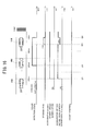
- FIG. 15 is a time chart illustrative of an operation (in the case of another vehicle) in one embodiment of the present disclosure
- FIG. 16 is a time chart illustrative of an operation (in the case of a step) in one embodiment of the present disclosure
- FIG. 17 is a time chart illustrative of an operation (in the case of grass) in one embodiment of the present disclosure.
- FIG. 18 is a view illustrative of another example of the decision level determination threshold.
- FIG. 1 is a conceptual view illustrative of a configuration of a vehicle in the present embodiment.
- a code MM denotes the vehicle.
- the vehicle MM includes a brake device that generates a brake force and a drive device that generates a drive force.
- the brake device is configured to include brake devices 12 respectively arranged for wheels 11 , a fluid pressure circuit 13 including piping connected to each of the brake devices 12 , and a brake controller 14 .
- the brake controller 14 is configured to control a brake force generated by each brake device 12 to a value depending on a brake force instruction value through the fluid pressure circuit 13 .
- the brake device 12 is not limited to a device that applies a brake force by fluid pressure, and may be an electric brake device or the like.
- the drive device is configured to include an engine 15 as a drive source, and an engine controller 16 configured to control the torque (drive force) generated by the engine 15 to a value depending on an acceleration instruction value.
- the drive source of the drive device is not limited to the engine 15 , and may be an electric motor, or may have a hybrid configuration in which a motor is combined with the engine 15 .
- the brake controller 14 and the engine controller 16 are each configured to receive an instruction value from a travel controller 10 which is a higher controller.
- the brake controller 14 is configured to receive a brake instruction (brake force instruction value) from the travel controller 10
- the engine controller 16 is configured to receive a drive instruction (acceleration instruction value) from the travel controller 10 .
- the vehicle MM is configured to include a surrounding environment recognition sensor 1 , a wheel speed sensor 2 , a steering angle sensor 3 , a shift position sensor 4 , a brake manipulation detection sensor 5 , an accelerator manipulation detection sensor 6 , a navigation device 7 , and an ignition switch 8 .
- the surrounding environment recognition sensor 1 is configured to recognize an obstacle in surroundings (at least ahead in a travel direction) of the vehicle MM, and to output the information (surrounding environment recognition information) to the travel controller 10 .
- the surrounding environment recognition sensor 1 is configured to include one or plural sonars (ultrasonic exploratory device) capable of detecting an obstacle.
- each sonar 1 a to 1 d is arranged at the front side and the rear side of the vehicle MM, respectively.
- the sonars 1 a to 1 d arranged at the front side of the vehicle MM are illustrated in FIG. 2 , the sonars 1 a to 1 d are arranged in alignment in the width direction of the vehicle MM.
- Each sonar is configured to emit a spherical surface transmission wave to a measuring object at every predefined time, and to measure the location, the distance, and the like of the obstacle by receiving a reflection wave of the transmission wave from the obstacle.
- each sonar is also configured to receive the reflection waves of the transmission waves emitted by its adjacent sonars.
- the shortest one of the ten detection distance values is employed as a distance between the vehicle MM and the obstacle.
- the wheel speed sensor 2 is configured to detect the speed of the wheel, and to output detected wheel speed information to the travel controller 10 .
- the wheel speed sensor 2 is configured with, for example, a pulse generator such as a rotary encoder for measuring a wheel speed pulse.
- the steering angle sensor 3 is configured to detect a steering angle of the steering wheel 20 , and to output detected steering angle information to the travel controller 10 .
- the steering angle sensor 3 is arranged at a steering shaft or the like. It is to be noted that the turning angle of the steering wheel may be detected as steering angle information.
- the shift position sensor 4 is configured to detect a shift position (drive instruction position, parking instruction position, neutral position, and the like), and to output the detected shift position to the travel controller 10 as shift information.
- the brake manipulation detection sensor 5 is configured to detect a presence or absence of manipulation or a manipulation amount of the brake pedal 18 .
- the detected brake pedal manipulation amount is output to the travel controller 10 .
- the brake pedal 18 is a manipulation element to be manipulated by a driver for instructing the speed deceleration.
- the accelerator manipulation detection sensor 6 is configured to detect a manipulation amount of the accelerator pedal 19 .
- the detected accelerator pedal manipulation amount is output to the travel controller 10 .
- the accelerator pedal 19 is a manipulation element to be manipulated by a driver for instructing the speed acceleration.
- the navigation device 7 is configured to include a GPS receiver, a map database, a display monitor, and the like, and is a device for performing a route search, route guidance, and the like.
- the navigation device 7 is configured to acquire road information such as a type of a road, a width of the road, and the like of the road on which the vehicle MM travels, based on the current location of the vehicle V acquired by using the GPS receiver and the road information stored in the map database.
- the vehicle MM includes an information presentation device, not illustrated.
- the information presentation device is configured to output a warning or another presentation in a sound or image in response to a control signal from the travel controller 10 .
- the information presentation device is configured to include, for example, a speaker to provide information to a driver in a buzzer or voice, and a display unit to provide information by presenting an image or text.
- the display unit may also use a display monitor of the navigation device 26 .
- the travel controller 10 is an electronic control unit including a CPU and peripheral devices such as a ROM, RAM, and the like, and is configured to carry out a drive assist process to avoid the obstacle.
- FIG. 3 is a block view illustrative of a configuration of the travel controller 10 .
- the travel controller 10 is configured to include a surrounding environment recognition information operation unit 10 A, a vehicle speed operation unit 10 B, a steering angle operation unit 10 C, and a shift position operation unit 10 D, a brake pedal manipulation information operation unit 10 E, an accelerator manipulation amount operation unit 10 F, an acceleration suppression activation determination unit 10 G, an acceleration suppression amount operation unit 10 H, a target throttle opening degree operation unit 10 I, a brake control amount operation unit 10 J, and a decision level storage unit 10 K.
- the surrounding environment recognition information operation unit 10 A is configured to recognize an environment surrounding the vehicle based on a signal from the surrounding environment recognition sensor 1 .
- information on the obstacle (the presence or absence of obstacle, the location of the obstacle, the distance between the vehicle MM and the obstacle) in the surrounding of the vehicle is recognized from the reflection waves detected by the sonars 1 a to 1 d arranged as the surrounding environment recognition sensor 1 .
- the reflection wave which was received at a timing immediately before the sonars 1 a to 1 d emit the transmission waves, is determined to be a noise emitted from the outside, and is excluded from a subject of the obstacle detection.
- the vehicle speed operation unit 10 B is configured to operate the vehicle speed based on the signal from the wheel speed sensor 2 .
- the steering angle operation unit 10 C is configured to operate the steering angle based on the signal from the steering angle sensor 3 .
- the shift position operation unit 10 D is configured to determine the shift position based on the signal from the shift position sensor 4 .
- the brake pedal manipulation information operation unit 10 E is configured to determine the brake manipulation amount based on the signal from the brake manipulation detection sensor 5 .
- the accelerator manipulation amount operation unit 10 F is configured to operate the manipulation amount of accelerator pedal 19 based on the signal from the accelerator manipulation detection sensor 6 .
- the acceleration suppression activation determination unit 10 G is configured to receive various pieces of information and to determine whether or not acceleration suppression control for suppressing the acceleration of the vehicle MM need to be carried out, as a drive assist process to avoid the obstacle.
- the acceleration suppression control includes drive force limit control for limiting the drive force of the vehicle MM and brake force control for generating a brake force in the vehicle MM.
- FIG. 4 is a flow chart illustrative of an acceleration suppression activation determination process procedure to be carried out by the acceleration suppression activation determination unit 10 G.
- the acceleration suppression activation determination process starts when the ignition switch 8 is turned on, and is carried out at every predefined sampling time.
- step S 110 the acceleration suppression activation determination unit 10 G acquires the surrounding environment recognition information from the surrounding environment recognition information operation unit 10 A, and processing goes to step S 115 .
- step S 115 the acceleration suppression activation determination unit 10 G determines whether or not the timing is immediately after the ignition switch 8 is turned on from the state where the ignition switch 8 is turned off. Then, when it is determined that the timing is not immediately after the ignition switch 8 is turned on, the processing goes to step S 125 . When it is determined that the timing is immediately after the ignition switch 8 is turned on, the processing goes to step S 128 .
- step S 125 the acceleration suppression activation determination unit 10 G determines whether or not there is an obstacle in the course ahead in the travel direction based on the surrounding environment recognition information recognized in the above step S 110 . Then, when there is an obstacle, the acceleration suppression activation determination unit 10 G determines a decision level of the obstacle.
- the decision level of the obstacle is determined depending on the type of obstacle (such as a wall, another vehicle, an edge stone, or a natural thing (grass)). Smaller values are set in the order of a wall, another vehicle, an edge stone, and a natural thing.
- FIG. 5 is a flow chart illustrative of a decision level determination process procedure to be carried out in step S 125 .
- the acceleration suppression activation determination unit 10 G determines whether or not there is an obstacle in the course ahead in the travel direction based on the surrounding environment recognition information recognized in the above step S 110 .
- the course of the vehicle MM is estimated based on the steering angle information.
- a range having a similar width to the vehicle MM in the estimated course of the vehicle MM is set as a course of the vehicle MM, and whether or not there is an obstacle in the course is determined.
- step S 125 b when it is determined that there is an obstacle, the processing goes to step S 125 b .
- step S 125 o the processing goes to step S 125 o to be described later.
- step S 125 b the acceleration suppression activation determination unit 10 G determines whether or not such a detected obstacle has been detected for the first time. In other words, in the process while the vehicle MM is approaching the obstacle, it is determined whether or not the obstacle has been detected for the first time. Then, when the obstacle was not detected at the previous sampling and the obstacle is detected at the current sampling, it is determined that the detection has been made for the first time and the processing goes to step S 125 c . On the other hand, when the detection has not been made for the first time, that is when the obstacle was also detected at the previous sampling, the processing goes to step S 125 d to be described later.
- step S 125 c the acceleration suppression activation determination unit 10 G acquires the distance from the current location of the vehicle MM to the obstacle as a first-time detection distance La, and the processing goes to step S 125 d.
- step S 125 d the acceleration suppression activation determination unit 10 G determines whether or not a height determination of the obstacle is possible.
- the height determination of the obstacle is assumed possible.
- the sonar 1 a when an edge stone is detected by the sonar 1 a , as illustrated in the upper section of FIG. 6A , in the transmission waves emitted from the sonar 1 a , the transmission wave emitted in the road surface direction (obliquely downward) is reflected by an edge stone, such a reflection wave is again reflected on the road surface, and the sonar 1 a receives the reflection wave.
- the transmission wave emitted by the sonar 1 a in the horizontal direction passes above the edge stone, and therefore the sonar 1 a does not receive the reflection wave of the transmission wave.
- the strength property of the reflection wave received by the sonar 1 a as illustrated in the lower section of FIG. 6A , has a single peak higher than an obstacle detection threshold.
- the sonar 1 a receives the reflection wave directly.
- the sonar 1 a receives both of the reflection wave of the transmission wave emitted obliquely downward and the reflection wave of the transmission wave emitted horizontally.
- the strength property of the reflection waves received by the sonar 1 a has two peaks higher than the obstacle detection threshold in a short period T 1 .
- T 1 is a length of time while it can be determined that the received reflection waves are the reflection waves from an identical obstacle.
- step S 125 e the processing goes to step S 125 g to be described later.
- step S 125 e the acceleration suppression activation determination unit 10 G acquires the distance from the current location of the vehicle MM to the obstacle as a height determination distance Lb, and the processing goes to step S 125 f .
- the height determination distance Lb is a distance from the vehicle MM to the obstacle at a time point when the height determination of the obstacle is enabled (the time point when it can be determined that the obstacle is a tall obstacle).
- step S 125 g the acceleration suppression activation determination unit 10 G determines whether or not an identical obstacle is detected by plural sonars. In this situation, it is determined whether or not such an identical obstacle is detected by at least two adjacent sonars. To be specific, in a case where two adjacent sonars receive the reflection wave (direct reflection wave) of the transmission wave emitted by oneself and the reflection wave (indirect reflection wave) of the transmission wave emitted by the other one, respectively, and the detection distance values are acquired from the direct reflection wave and the indirect reflection wave, it is determined that an identical obstacle is detected by these two sonars.
- step S 125 h when it is determined for the first time that the identical obstacle is detected by plural sonars, the processing goes to step S 125 h .
- the processing goes to step S 125 i to be described later.
- step S 125 h the acceleration suppression activation determination unit 10 G acquires the distance from the current location of the vehicle MM to an obstacle as a plural-number detection distance Lc, and the processing goes to step S 125 i .
- the plural-number detection distance Lc is a distance from the vehicle MM to the obstacle at the time point when the identical obstacle is detected by plural sonars.
- step S 125 i the acceleration suppression activation determination unit 10 G determines whether or not the detected obstacle has a decision level of Lv 3 (high level) based on the first-time detection distance La, the height determination distance Lb, the plural-number detection distance Lc, and the distance difference Ld.
- step S 125 i the acceleration suppression activation determination unit 10 G determines that the decision level of the detected obstacle is Lv 3 (high level), when the first-time detection distance La is equal to or longer than a threshold TH 13 , the height determination distance Lb is equal to or longer than a threshold TH 23 , the plural-number detection distance Lc is equal to or longer than a threshold TH 33 , and the distance difference Ld is equal to or shorter than a threshold TH 43 .
- FIG. 7 is a view illustrative of an example of the decision level determination threshold.
- a numerical unit is centimeter (cm).
- step S 125 i when it is determined that a condition of Lv 3 is satisfied in step S 125 i , the processing goes to step S 125 j .
- the decision level of the detected obstacle is set to Lv 3 (high), and the processing goes to step S 125 p to be described later.
- step S 125 k when it is determined that the condition of Lv 3 is not satisfied in step S 125 i , the processing goes to step S 125 k.
- step S 125 k the acceleration suppression activation determination unit 10 G determines whether or not the decision level of the detected obstacle is Lv 2 (medium level) based on the first-time detection distance La, the height determination distance Lb, the plural-number detection distance Lc, and the distance difference Ld.
- the decision level of the detected obstacle is Lv 2 (medium level)
- the threshold TH 12 300 cm
- the threshold TH 22 150 cm
- the threshold TH 32 230 cm
- the threshold TH 42 250 cm.
- step S 125 k when it is determined that a condition of Lv 2 is satisfied in step S 125 k , the processing goes to step S 125 l .
- the decision level of the detected obstacle is set to Lv 2 (medium), and the processing goes to step S 125 p to be described later.
- step S 125 m when it is determined that the condition of Lv 2 is not satisfied in step S 125 k , the processing goes to step S 125 m.
- step S 125 m the acceleration suppression activation determination unit 10 G determines whether or not the decision level of the detected obstacle is Lv 1 (low level) based on the first-time detection distance La, the height determination distance Lb, the plural-number detection distance Lc, and the distance difference Ld.
- the decision level of the detected obstacle is Lv 1 (low level)
- the threshold TH 11 250 cm
- the threshold TH 21 100 cm
- the threshold TH 31 80 cm
- the threshold TH 41 300 cm.
- step S 125 n the processing goes to step S 125 n .
- the decision level of the detected obstacle is set to Lv 1 (low), and the processing goes to step S 125 p to be described later.
- step S 125 o the processing goes to step S 125 o .
- the decision level of the detected obstacle is set to Lv 0 (null), and the decision level determination process ends.
- step S 125 p the acceleration suppression activation determination unit 10 G determines whether or not the obstacle is lost in a short distance (for example, within a range of 50 cm ahead in the travel direction of the vehicle MM). In other words, it is determined that whether or not the state where there is an obstacle ahead in the travel direction of the vehicle MM can be kept, even when the distance between the vehicle MM and the obstacle is shorter than a short distance threshold (50 cm). Then, when it is determined that the obstacle is lost in the short distance, the processing goes to step S 125 o . When it is determined that the obstacle is not lost in the short distance, the processing goes to step S 125 q.
- a short distance for example, within a range of 50 cm ahead in the travel direction of the vehicle MM.
- step S 125 q the acceleration suppression activation determination unit 10 G sets the decision level of the detected obstacle to Lv 3 (high), and the decision level determination process ends.
- the decision level is raised to Lv 3
- the decision level is lowered to Lv 0 .
- step S 125 the decision level is set based on the information on the obstacle existing ahead in the travel direction of the vehicle MM.
- the decision level of the obstacle is updated to a final decision level in consideration of a travel state or drive state of the vehicle MM to be described later.
- the decision level stored in the decision level storage unit 10 K is used to carry out the acceleration suppression control to avoid the obstacle.
- step S 128 the acceleration suppression activation determination unit 10 G carries out a decision level acquisition process of acquiring the decision level of the obstacle stored in the decision level storage unit 10 K.
- FIG. 8 is a flow chart illustrative of a decision level acquisition process procedure to be carried out in step S 128 .
- step S 128 a the acceleration suppression activation determination unit 10 G reads a stored level of the obstacle stored in the decision level storage unit 10 K and the distance between the vehicle MM and the obstacle, and the processing goes to step S 128 b.
- step S 128 b the acceleration suppression activation determination unit 10 G detects the distance between the vehicle MM and the obstacle based on the surrounding environment recognition information recognized in the above step S 110 . It is to be noted that, in one embodiment, at least two sonars that have detected the obstacle immediately before the ignition is turned off are configured to detect the distance between the vehicle MM and the obstacle.
- step S 128 c the acceleration suppression activation determination unit 10 G calculates an error between the distance between the vehicle MM and the obstacle (obstacle distance storage value) read in the above step S 128 a and the distance between the vehicle MM and the obstacle (obstacle distance detection value) detected in the above step S 128 b.
- step S 128 d the acceleration suppression activation determination unit 10 G determines whether or not the error calculated in step S 128 c falls within an allowable range.
- the error falls within a range of + ⁇ 30 cm, it is determined that the error falls within such an allowable range.
- step S 128 e determines that the decision level stored in the decision level storage unit 10 K is valid.
- the decision level stored in the decision level storage unit 10 K is used as a decision level of the obstacle existing ahead in the travel direction of the vehicle MM, and the decision level acquisition process ends.
- step S 128 d when it is determined in step S 128 d that the error falls out of an allowable range, the processing goes to step S 128 f and determines that the decision level stored in the decision level storage unit 10 K is invalid. In this case, the decision level of the obstacle existing ahead in the travel direction of the vehicle MM is set to an initial state (Lv 0 ), and the decision level acquisition process ends.
- step S 130 the acceleration suppression activation determination unit 10 G acquires the speed of the vehicle MM from the vehicle speed operation unit 10 B.
- step S 140 the acceleration suppression activation determination unit 10 G determines whether or not the vehicle speed acquired in the above step S 130 is lower than a predefined vehicle speed threshold (for example, 15 km/h). Then, when the vehicle speed is lower than the vehicle speed threshold, it is determined that the vehicle MM is travelling at a low speed, and then the processing goes to step S 150 . When the vehicle speed is equal to or higher than the vehicle speed threshold, it is determined that the acceleration suppression control does not have to be activated, and the processing goes to step S 145 .
- a predefined vehicle speed threshold for example, 15 km/h
- step S 150 the acceleration suppression activation determination unit 10 G acquires the brake pedal manipulation information from the brake pedal manipulation information operation unit 10 E, and the processing goes to step S 160 .
- step S 160 the acceleration suppression activation determination unit 10 G determines whether there is a presence or absence of the brake pedal manipulation based on the brake pedal manipulation information acquired in the above step S 150 . Then, when the absence of the brake pedal manipulation is determined, the processing goes to step S 170 . When the presence of the brake pedal manipulation is determined, the processing goes to step S 145 .
- step S 170 the acceleration suppression activation determination unit 10 G acquires the accelerator manipulation amount from the accelerator manipulation amount operation unit 10 F, and the processing goes to step S 180 .
- step S 180 the acceleration suppression activation determination unit 10 G determines whether or not the accelerator manipulation amount acquired in step S 170 is equal to or larger than a predefined accelerator manipulation amount threshold.
- the accelerator manipulation amount threshold is set to, for example, a manipulation amount corresponding to 50% the accelerator opening degree of the accelerator pedal 19 . Then, when the accelerator manipulation amount is equal to or larger than the accelerator manipulation amount threshold, processing goes to step S 182 . When the accelerator manipulation amount is smaller than the accelerator manipulation amount threshold, processing goes to step S 145 .
- step S 182 the acceleration suppression activation determination unit 10 G operates an approach degree D to the obstacle.
- the distance between the vehicle MM and the obstacle is set as the approach degree D.
- step S 184 the acceleration suppression activation determination unit 10 G determines whether or not the approach degree D calculated in the above step S 182 is equal to or higher than a predefined approach degree threshold.
- a predefined value for example, 3.5 meters
- step S 186 when the approach degree D is equal to or higher than the approach degree threshold, it is determined that the acceleration suppression control should be carried out, and the processing goes to step S 186 .
- the approach degree D is lower than the approach degree threshold, it is determined that it is sufficient to do an avoidance action from the obstacle, and the processing goes to step S 122 .
- the approach degree D does not have to be a distance itself between the vehicle MM and the obstacle.
- a risk potential such as a Time To Contact TTC in which the vehicle MM arrives at the current location of the obstacle can be used for a value of the approach degree D.
- step S 186 the acceleration suppression activation determination unit 10 G determines that the acceleration suppression activation condition is satisfied, the decision level determined in step S 125 is set as an acceleration suppression activation determination result, and the processing goes to step S 190 .
- step S 190 the acceleration suppression activation determination result determined in either the above step S 145 or step S 186 is output to the acceleration suppression amount operation unit 10 H and is also stored in the decision level storage unit 10 K, and the acceleration suppression activation determination process ends.
- the decision level is set depending on the type of obstacle based on the first-time detection distance La, the height determination distance Lb, the plural-number detection distance Lc, and the distance difference Ld that is a difference between the first-time detection distance La and the height determination distance Lb.
- the decision level storage unit 10 K is configured to store the decision level that has been set most recently before the ignition is turned off and the distance between the vehicle MM and the obstacle that has been detected most recently before the ignition is turned off. Immediately after the ignition is turned on, by comparing the obstacle distance storage value with the obstacle distance detection value, the validity of the decision level stored in the decision level storage unit 10 K is determined to be used for the acceleration suppression control to avoid the obstacle.
- FIG. 9A to FIG. 9C are views illustrative of differences between the obstacle distance detection result and the height determination result depending on the type of obstacle.
- the obstacle in FIG. 9A , the obstacle is a wall, in FIG. 9B , the obstacle is another vehicle, and in FIG. 9C , the obstacle is an edge stone.
- the first-time detection distance La, the height determination distance Lb, and the distance difference Ld between the first-time detection distance La and the height determination distance Lb are varied depending on the type of obstacle.
- the existence of the obstacle and the obstacle that is tall can be detected from a comparatively longer distance.
- the first-time detection distance La tends to be shorter than that of the wall.
- the distance difference Ld between the first-time detection distance La and the height determination distance Lb of another vehicle becomes longer than that of a wall.
- plural sonars are configured to detect the obstacle.
- a thin object such as a pole or a pylon
- plural sonars are not configured to detect the obstacle.
- the detection performance is poor and the reflection wave tends to be hardly received in a stable manner, unless the vehicle MM gets closer within 1 meter, for example.
- the decision level when the obstacle is a wall, the decision level is Lv 3 that is a maximum level.
- the decision level varies Lv 1 to Lv 3 depending on the shape and size.
- the decision level when the obstacle is not tall such as an edge stone or a step, the decision level is Lv 0 .
- the decision level can be Lv 1 until it is lost in a short distance.
- the decision level can be Lv 2 until it is lost in a short distance.
- the decision level in the case of a natural thing, a thin object, a walker, a bicycle, or the like, the decision level is Lv 0 .
- a control manner of the acceleration suppression control is changed depending on the decision level of the obstacle (the type of the obstacle).
- the acceleration suppression amount operation unit 10 H and the brake control amount operation unit 10 J are configured to make such a change in the control manner, upon receipt of the decision level of the obstacle that has been set by the acceleration suppression activation determination unit 10 G.
- the acceleration suppression amount operation unit 10 H is configured to carry out the acceleration suppression amount operation process as illustrated in FIG. 11 at every predefined sampling time.
- step S 210 the acceleration suppression amount operation unit 10 H acquires the decision level of the obstacle as an acceleration suppression activation determination result from the acceleration suppression activation determination unit 10 G, and processing goes to step S 220 .
- step S 220 the acceleration suppression amount operation unit 10 H acquires acceleration suppression process selection information.
- the acceleration suppression process selection information is an accelerator manipulation amount acquired from the accelerator manipulation amount operation unit 10 F.
- step S 230 the acceleration suppression amount operation unit 10 H determines whether or not the decision level of the obstacle acquired in the above step S 210 is Lv 3 . Then, when the decision level is Lv 3 , the processing goes to step S 240 . When the decision level is not Lv 3 , the processing goes to step S 250 to be described later.
- step S 240 the acceleration suppression amount operation unit 10 H operates a second acceleration suppression amount to strongly activate the drive force limit control, and the processing goes to step S 280 to be described later.
- the acceleration suppression amount is operated such that the throttle opening degree (acceleration instruction value) is not larger than a second limit value (for example, 0%) based on the accelerator manipulation amount acquired in the above step S 220 .
- step S 250 the acceleration suppression amount operation unit 10 H determines whether or not the decision level of the obstacle acquired in the above step S 210 is either Lv 2 or Lv 1 . Then, when the decision level is either Lv 2 or Lv 1 , the processing goes to step S 260 .
- step S 260 the acceleration suppression amount operation unit 10 H operates a first acceleration suppression amount to weakly activate the drive force limit control, and the processing goes to step S 280 to be described later.
- the acceleration suppression amount is operated such that the throttle opening degree (acceleration instruction value) is not larger than a first limit value (for example, 25%) based on the accelerator manipulation amount acquired in the above step S 220 .
- step S 250 when it is determined in step S 250 that the decision level is Lv 0 , the processing goes to step S 270 .
- the acceleration suppression amount is set with “0” so that the drive force limit control should not be activated, and the processing goes to step S 280 .
- step S 280 the acceleration suppression amount operation unit 10 H outputs the acceleration suppression amount that has been operated to the target throttle opening degree operation unit 10 I, and the acceleration suppression amount operation process ends.
- the target throttle opening degree operation unit 10 I outputs the throttle opening degree ⁇ * that has been operated to the engine controller 16 , and the engine controller 16 controls the engine that is a drive source so that the throttle opening degree should be the target throttle opening degree ⁇ *.
- FIG. 12 is a flow chart illustrative of a brake control amount operation process procedure to be carried out by the brake control amount operation unit 10 J.
- step S 310 the brake control amount operation unit 10 J acquires the decision level of the obstacle as an acceleration suppression activation determination result from the acceleration suppression activation determination unit 10 G, and processing goes to step S 320 .
- step S 320 the brake control amount operation unit 10 J determines whether or not the acceleration suppression activation determination result acquired from the acceleration suppression activation determination unit 10 G is the acceleration suppression activation condition non-satisfied, that is to say, whether or not the decision level is Lv 0 . Then, when it is determined that the decision level is not Lv 0 , the processing goes to step S 330 . When it is determined that the decision level is Lv 0 , the processing goes to step S 370 to be described later.
- step S 330 the brake control amount operation unit 10 J determines whether or not the distance between the vehicle MM and the obstacle falls within a short distance (for example, 50 cm). Then, when it falls within a short distance, the processing goes to step S 340 . When it does not fall within a short distance, the processing goes to step S 350 to be described later.
- a short distance for example, 50 cm
- step S 340 the brake control amount operation unit 10 J operates a second brake amount to strongly activate the brake force control, and the processing goes to step S 380 to be described later.
- the brake amount is operated such that the brake force (brake force instruction value) is the second brake force (corresponding to, for example, 0.5 G).
- step S 350 the brake control amount operation unit 10 J determines whether or not the decision level of the obstacle acquired in the above step S 310 is either Lv 3 or Lv 2 . Then, when the decision level is either Lv 3 or Lv 2 , the processing goes to step S 360 .
- step S 360 the brake control amount operation unit 10 J operates the first brake amount to weakly activate the brake force control, and the processing goes to step S 380 to be described later.
- the brake force is operated such that the brake force (brake force instruction value) is the first brake force (corresponding to 0.25 G, for example).
- step S 350 when it is determined in step S 350 that the decision level is Lv 0 , the processing goes to step S 370 .
- the control amount is set to “0” so that the brake force control should not be activated, and the processing goes to step S 380 .
- step S 380 the brake control amount operation unit 10 J outputs the control amount that has been operated to the brake controller 14 , and the brake control amount operation process ends.
- the brake controller 14 controls the brake force such that the brake force generated by the brake device 12 should be a brake force operated by the brake control amount operation unit 10 J.
- FIG. 13 is a time chart illustrative of an example of the operation while the vehicle MM is traveling at a low speed under 15 km/h toward a wall.
- the travel controller 10 detects a wall for the first time as an obstacle existing ahead in the travel direction of the vehicle MM at a location that is 350 cm short of the wall (at a time point t 1 ) (step S 125 a : Yes, step S 125 b : Yes in FIG. 5 )
- the distance between the vehicle MM and the obstacle at this time is acquired as the first-time detection distance La (step S 125 c ).
- the first-time detection distance La is 350 cm.
- the distance between the vehicle MM and the obstacle at the time point t 1 is acquired as the plural-number detection distance Lc (step S 125 h ).
- the plural-number detection distance Lc is 350 cm.
- the height determination distance Lb cannot be acquired.
- the decision level of the obstacle cannot be determined. Accordingly, at the time point t 1 , the decision level remains as an initial state (Lv 0 ).
- step S 250 when a driver makes an accelerator operation at the time point t 1 , the drive force limit control is not carried out (step S 250 : No in FIG. 11 ), and the engine is controlled such that the throttle opening degree depends on the driver's accelerator manipulation amount.
- the decision level is Lv 0 , the brake force control is not carried out, either (step S 350 : No in FIG. 12 ).
- step S 125 d when the reflection wave having two peaks is received at a location that is 300 cm short of the wall (at a time point t 2 ) as illustrated in the lower section of FIG. 6B , it is determined that the detected obstacle is a tall obstacle that is as tall as the vehicle or taller than the vehicle MM (step S 125 d : Yes). Then, the distance between the vehicle MM and the obstacle at this time is acquired as the height determination distance Lb (step S 125 e ). In other words, the height determination distance La is 300 cm. Thus, the distance difference Ld between the first-time detection distance La and the height determination distance Lb is 50 cm (step S 125 f ).
- the acceleration suppression amount is operated so that the throttle opening degree (acceleration instruction value) should not be higher than 0% (step S 240 ), and the engine is controlled based on the acceleration suppression amount that has been operated. Accordingly, the throttle opening degree is limited to 0%.
- the strong drive force limit control the acceleration of the vehicle MM is suppressed with certainty.
- the weak brake force control for the purpose of warning is activated (step S 360 ). Accordingly, the brake force corresponding to 0.25 G is generated, so that the vehicle speed can be decreased.
- step S 330 when the driver continues the accelerator operation and the vehicle MM reaches a location that is 50 cm short of the wall at a time point t 3 (step S 330 : Yes), the travel controller 10 activates the strong brake force control for the purpose of avoiding a contact with the wall (step S 340 ). Accordingly, the brake force corresponding to 0.5 G is generated.
- the throttle opening degree is limited to 0%, and in addition, the brake force corresponding to 0.25 G is generated. Further, when the vehicle MM approaches at a short distance (less than 50 cm) from the obstacle, the brake force corresponding to 0.5 G is generated.
- the decision level storage unit 10 K is configured to store the decision level that has been set most recently before the ignition switch 8 is turned off, and the distance between the vehicle MM and the obstacle that has been set most recently before the ignition switch 8 is turned off.
- step S 115 when the driver turns on the ignition switch 8 at a time point t 4 of FIG. 14 (step S 115 : Yes), the decision level of the obstacle stored in the decision level storage unit 10 K is read (step S 128 a of FIG. 8 ). Also, in this situation, the sonars 1 a to 1 d detect the distance to the obstacle existing ahead in the travel direction of the vehicle MM (step S 128 b ).
- step S 128 d Since the parked location of the vehicle MM while the ignition is off is not changed, when the obstacle existing ahead is a wall, the distance to the wall detected when the ignition is turned on is equal to the distance stored in the decision level storage unit 10 K. Thus, since an error between the detection value and the storage value falls within an allowable range (step S 128 d : Yes), it is determined at a time point t 5 immediately after the ignition is turned on that the decision level stored in the travel controller 10 is valid, the obstacle existing ahead in the travel direction is assumed to be a wall, and the decision level is set to Lv 3 (step S 128 e ).
- the throttle opening degree is limited to 0% by the drive force limit control.
- the driver makes an accelerator manipulation to move backward with the shift position being set at the D range, in the situation where there is a wall ahead the vehicle MM, the acceleration of the vehicle MM can be suppressed with certainty.
- the decision level of the obstacle cannot be determined from the information on the obstacle existing ahead that has been detected in a parking state at the time when the ignition is turned on.
- the decision level of the obstacle stored in the decision level storage unit 10 K makes it possible to understand the decision level of the obstacle promptly and appropriately at the time of turning on the ignition. Therefore, suited acceleration suppression control can be made.
- the engine is controlled such that the throttle opening degree depends on the driver's accelerator manipulation amount.
- the distance between the vehicle MM and the obstacle at this time is acquired as the first-time detection distance La (step S 125 c ).
- the first-time detection distance La is 250 cm.
- the distance between the vehicle MM and the obstacle at the time point t 12 is acquired as the plural-number detection distance Lc (step S 125 h ).
- the plural-number detection distance Lc is 250 cm.
- the decision level remains as an initial state (Lv 0 ) and the acceleration suppression control is not activated. Therefore, the engine control depending on the driver's accelerator manipulation amount continues.
- the first-time detection distance La and the height determination distance Lb tend to be shorter.
- step S 125 m Yes
- the decision level is set to Lv 1 (step S 125 n ).
- the acceleration suppression amount is operated such that the throttle opening degree (acceleration instruction value) is not higher than 25% at a time point t 13 (step S 260 ), the engine is controlled based on the acceleration suppression amount that has been operated. Accordingly, the throttle opening degree is limited to 25%. Thus, the acceleration of the vehicle MM is suppressed by activating the weak drive force limit control. In addition, since the decision level is Lv 1 (step S 350 : No), the brake force control is not activated (step S 370 ).
- the travel controller 10 determines whether or not the obstacle is lost (step S 125 p ).
- the obstacle is another vehicle, and in order to maintain the state where the obstacle is detected even in the short distance (step S 125 p : Yes), the decision level of the obstacle is raised from Lv 1 to Lv 3 (step S 125 q ). Accordingly, the travel controller 10 activates the strong drive force limit control to limit the throttle opening degree to 0% (step S 240 ).
- step S 330 the strong brake force control is activated for the purpose of avoiding a contact with another vehicle to generate the brake force corresponding to 0.5 G (step S 340 ).
- the distance between the vehicle MM and the obstacle and the decision level of the obstacle at that time point are stored in the decision level storage unit 10 K.
- step S 128 d No
- the validity of the decision level is determined.
- the stored decision level is made invalid so that the inappropriate acceleration suppression control can be prevented.
- FIG. 16 is a time chart illustrative of an operation when a step having the decision level that can be Lv 1 is detected as an obstacle.
- step S 125 m when the obstacle is detected for the first time at a time point t 22 at a location that is 250 cm short of the step and the height is determined at a time point t 22 at a location that is 100 cm short of the step, the condition of Lv 1 is satisfied (step S 125 m : Yes). It is determined that there is a high possibility that the detected obstacle is another vehicle, an edge stone, or a step, and the decision level is set to Lv 1 (step S 125 n ).
- the acceleration suppression amount is operated so that the throttle opening degree (acceleration instruction value) should not be higher than 25% (step S 260 ), and the engine is controlled based on the acceleration suppression amount that has been operated. Accordingly, the throttle opening degree is limited to 25%. In this manner, the acceleration of the vehicle MM is suppressed by activating the weak drive force limit control.
- the brake force control is not activated (step S 370 ).
- the travel controller 10 determines that the obstacle is lost in a short distance and lowers the decision level of the obstacle from Lv 1 to Lv 0 (step S 125 o ). Accordingly, the travel controller 10 switches the drive force limit control to non-activation (step S 270 ). In addition, the brake force control remains as non-activation (step S 370 ).
- the decision level of the obstacle is Lv 1 (or, Lv 2 ). Even if it cannot be determined whether the obstacle is another vehicle, an edge stone, or a step, whether or not the obstacle is lost in a short distance is determined, so that the type of the obstacle can be determined. In other words, when the obstacle is not lost in a short distance, it is determined that there is a high possibility that the obstacle is another vehicle instead of a short obstacle such as an edge stone of a step and then the decision level is raised to Lv 3 .
- the strong drive force limit control and the strong brake force control can be activated together, so that a contact with another vehicle can be avoided appropriately.
- step S 125 m the conditions of Lv 3 to Lv 1 are not satisfied. It is determined that there is a high possibility that the detected obstacle is a natural thing or a thin object, and the decision level is set to Lv 0 (step S 125 o ).
- the engine is controlled such that the throttle opening degree depends on the driver's accelerator manipulation amount (step S 270 ). Also, the brake force control is made to be non-activated (step S 370 ).
- the decision level is maintained in Lv 0 , although the height determination is made or the obstacle is not lost in a short distance. Therefore, it is possible to prevent activation of the acceleration suppression control to avoid a natural thing with certainty.
- the distance between the vehicle MM and the obstacle, and the decision level of the obstacle at that time are stored in the decision level storage unit 10 K.
- step S 128 d Yes
- step S 128 f it is determined that the decision level stored in the decision level storage unit 10 K is valid and the obstacle existing ahead is assumed to be a natural thing to set the decision level to Lv 0
- the surrounding environment recognition sensor 1 corresponds to an in-vehicle sonar
- the acceleration suppression amount operation unit 10 H and the brake control amount operation unit 10 J correspond to an acceleration suppression controller
- the decision level storage unit 10 K corresponds to an obstacle type storage unit and an obstacle distance storage unit.
- step S 125 d corresponds to an obstacle height determination unit
- step S 125 i to step S 125 q correspond to an obstacle type determination unit
- step S 128 c to step S 128 f correspond to a validity determination unit.
- the travel controller 10 is configured to determine the type of an obstacle based on the first-time detection distance La that is a distance between the vehicle MM and the obstacle when it is determined by the sonars 1 a to 1 d for the first time that the obstacle is existing, and the height determination distance Lb that is a distance between the vehicle MM and the obstacle when it is determined by the sonars 1 a to 1 d for the first time that the obstacle is a tall one. Then, when it is determined that the vehicle MM has approached the obstacle at an approach degree equal to or higher than a predefined approach degree based on the distance between the vehicle MM and the obstacle, the travel controller 10 is configured to carry out the acceleration suppression control in a control manner depending on a determination result of the obstacle type.
- a condition of the magnitude of a control amount or activation/non-activation of the acceleration suppression control can be changed.
- appropriate acceleration suppression control depending on the type of the obstacle is enabled, so that the drive assist to avoid an obstacle can be given appropriately.
- the travel controller 10 is configured to determine that an obstacle existing ahead in the travel direction of the vehicle MM is a tall obstacle, upon receipt of a reflection wave having two strong peaks higher than a predefined obstacle detection threshold in a certain period, with respect to a single emission of transmission wave from each of the sonars 1 a to 1 d .
- the travel controller 10 is configured to utilize the fact that the transmission waves that have been emitted to the lower part of the obstacle by the sonar are received as a reflection wave reflected in the order of the obstacle and a road surface, and then returned, and a reflection wave emitted horizontally by the sonar, reflected directly, and then returned.
- the travel controller 10 is configured to determine a wall, a vehicle, an edge stone, a natural thing, as the type of the obstacle.
- the travel controller 10 is configured to set an obstacle decision level as an index to represent the type of the obstacle, and to set the obstacle decision level to a lower value in the order of a wall, a vehicle, an edge stone, and a natural thing.
- the travel controller 10 is configured to set the obstacle decision level to be higher, as the first detection distance La is longer.
- the travel controller 10 is configured to determine the type of the obstacle as a natural thing, when the first-time detection distance La is shorter than a natural thing detectable distance where reflection waves from the natural thing of the transmission waves emitted by the sonars 1 a to 1 d can be received stably.
- the travel controller 10 is configured to determine the type of the obstacle as a natural thing. Accordingly, such a detected obstacle can be recognized as a natural thing appropriately.
- the travel controller 10 is configured to set the obstacle decision level to be higher, as the height determination distance Lb is longer. Accordingly, when the obstacle that is a tall obstacle can be detected even from a distant location, a large-sized obstacle having a simple shape such as a wall can be determined.
- the travel controller 10 is configured to set the obstacle decision level to be higher, as the distance Ld obtained by subtracting the height determination distance Lb from the first-time detection distance La is shorter. Accordingly, in a case where the first-time detection can be made relatively promptly but the height determination is difficult to be made depending on the surface processing of the obstacle or the road surface condition, such as a case where the obstacle that is a short obstacle (an edge stone and a step) has a surface that can easily reflect the transmission wave emitted by the sonar, the obstacle decision level can be set to low. Therefore, it is possible to restrain an erroneous determination that a short obstacle is a wall or another vehicle.
- the travel controller 10 is configured to set the obstacle decision level to be higher, as the plural-number detection distance Lc that is a distance between the vehicle MM and the obstacle is longer, when a reflection waves from the identical obstacle of the transmission waves emitted by at least two adjacent sonars are received for the first time. Accordingly, an erroneous detection of the obstacle can be prevented.
- the obstacle decision level is set to be higher, when simultaneous detections made by plural sonars are possible even from a distant location, the probability of the obstacle detection when an obstacle is a wall can be improved.
- the travel controller 10 is configured to set the obstacle decision level to the maximum level, while the state where it is determined by the sonars 1 a to 1 d that an obstacle exists ahead in the travel direction of the vehicle MM is maintained, even when the distance between the vehicle MM and the obstacle is shorter than a predefined short distance threshold. Also, when the distance between the vehicle MM and the obstacle becomes shorter than the short distance threshold, and it is determined that the obstacle does not exist any longer from the state where it is determined by the sonars 1 a to 1 d that an obstacle exists ahead in the travel direction of the vehicle MM, the obstacle decision level is set to the minimum level.
- the travel controller 10 is configured to carry out the drive force limit control as the acceleration suppression control to avoid the obstacle, such that the acceleration instruction value depending on the accelerator pedal manipulation amount is limited to the acceleration limit value depending on the obstacle decision level as an upper limit.
- the acceleration limit value is set to a smaller value, as the obstacle decision level is higher. Accordingly, the acceleration limit value of the drive force suppression control is set to be smaller to a wall or another vehicle, so that the acceleration suppression effect can be brought out sufficiently. Also, the acceleration limit value of the drive force limit control is set to be larger to an edge stone or a natural thing so as to permit the acceleration. Hence, it is possible to restrain annoying feeling, which is caused by strongly activating the acceleration suppression control, from being given to a driver. (12)
- the travel controller 10 is configured to carry out the brake force control of generating the brake force onto the vehicle depending on the distance between the vehicle MM and the obstacle, as the acceleration suppression control to avoid the obstacle.
- the travel controller 10 is configured to store the type of the obstacle that has been determined based on the first detection distance La and the height determination distance Lb.
- the travel controller 10 is configured to carry out the acceleration suppression control in a control manner according to the stored obstacle type based on the distance between the vehicle MM and the obstacle, when it is determined that the vehicle MM has approached the obstacle at an approach degree equal to or higher than a predefined approach degree, at the time of turning on the ignition.
- the decision level of the obstacle is stored, so that the stored decision level is used for the acceleration suppression control at the time of turning on the ignition.
- the travel controller 10 is configured to determine the validity of the stored obstacle type, and then to use it for the acceleration suppression control at the time of turning on the ignition. Accordingly, it is possible to improve the reliability of the drive assist to avoid the obstacle at the time of turning on the ignition.
- the travel controller 10 is configured to determine at the time of turning on the ignition that the stored obstacle type is valid, when a difference between the stored distance to the obstacle and the detected distance to the obstacle by the sonars 1 a to 1 d falls within an allowable range. Accordingly, in a case where the obstacle has moved away or has been changed to another one until the ignition is turned on after the ignition is turned off, the stored obstacle type can be considered invalid. Thus, it is possible to suppress the activation of inappropriate acceleration suppression control.
- the first-time detection distance La that is a distance between the vehicle MM and the obstacle when it is determined by the sonars 1 a to 1 d for the first time that the obstacle exists, and the height determination distance Lb that is a distance between the vehicle MM and the obstacle when it is determined by the sonars 1 a to 1 d for the first time that the obstacle is a tall one are detected.
- the type of the obstacle is determined.
- the acceleration suppression control is carried out in a control manner depending on the type of the obstacle that has been determined.
- the decision level is determined by use of the decision level determination threshold illustrated in FIG. 7 has been described.
- the value of each threshold can be set appropriately depending on the sensitivity of the sonar or the travel environment (such as visibility).
- the decision level determination threshold to be set according to the vehicle speed may be used. Accordingly, the decision level determination can be made in consideration of a delay in the speed detection.
- the present disclosure is applied to the acceleration suppression control to avoid the obstacle has been described. However, the present disclosure may be used in combination of acceleration suppression control at the time of parking the vehicle.
- a camera is provided as the surrounding environment recognition sensor 1 , so that the surrounding environment recognition information operation unit 10 A can recognize the parking frame from the image captured by the camera. Then, it is determined whether or not there is an obstacle existing in the course ahead in the travel direction while the vehicle is being manipulated for parking, the acceleration suppression control for parking the vehicle at an intended parking location is carried out. In addition, when there is an obstacle existing ahead the parking frame, the acceleration suppression control depending on the decision level of the obstacle is carried out. Thus, the acceleration suppression effect can be brought out sufficiently, even if the accelerator pedal is mistakenly manipulated while the vehicle is being manipulated for parking. (3) In the above-described embodiment, the case where both of the drive force limit control and the brake force control are carried out as the acceleration suppression control has been described. However, only either one of them may be carried out. In particular, as the acceleration suppression control at the time of turning on the ignition, sufficient effects are obtainable by carrying out only the drive force limit control.
- a control manner of the acceleration suppression control can be changed depending on the type of the obstacle.
- the magnitude of the control amount or activation/non-activation of the acceleration suppression control can be changed depending on the type of the obstacle.
Landscapes
- Engineering & Computer Science (AREA)
- Remote Sensing (AREA)
- Radar, Positioning & Navigation (AREA)
- Automation & Control Theory (AREA)
- Physics & Mathematics (AREA)
- Mechanical Engineering (AREA)
- Transportation (AREA)
- General Physics & Mathematics (AREA)
- Computer Networks & Wireless Communication (AREA)
- Acoustics & Sound (AREA)
- Chemical & Material Sciences (AREA)
- Combustion & Propulsion (AREA)
- Human Computer Interaction (AREA)
- Control Of Driving Devices And Active Controlling Of Vehicle (AREA)
- Traffic Control Systems (AREA)
- Measurement Of Velocity Or Position Using Acoustic Or Ultrasonic Waves (AREA)
Abstract
Description
θ*=θ1−Δθ
where θ1 is a throttle opening degree depending on the accelerator manipulation amount, and Δθ is an acceleration suppression amount.
(3) The
(4) The
(5) The
(6) The
(7) The
(8) The
(9) The
(10) The
(11) The
(12) The
(13) The
(14) The
(15) The
(16) The first-time detection distance La that is a distance between the vehicle MM and the obstacle when it is determined by the
(2) In the above-described embodiment, the case where the present disclosure is applied to the acceleration suppression control to avoid the obstacle has been described. However, the present disclosure may be used in combination of acceleration suppression control at the time of parking the vehicle. In this case, a camera is provided as the surrounding
(3) In the above-described embodiment, the case where both of the drive force limit control and the brake force control are carried out as the acceleration suppression control has been described. However, only either one of them may be carried out. In particular, as the acceleration suppression control at the time of turning on the ignition, sufficient effects are obtainable by carrying out only the drive force limit control.
Claims (16)
Applications Claiming Priority (5)
| Application Number | Priority Date | Filing Date | Title |
|---|---|---|---|
| JP2012259183 | 2012-11-27 | ||
| JP2012259185 | 2012-11-27 | ||
| JP2012-259185 | 2012-11-27 | ||
| JP2012-259183 | 2012-11-27 | ||
| PCT/JP2013/006650 WO2014083787A1 (en) | 2012-11-27 | 2013-11-12 | Vehicular acceleration suppression apparatus, and vehicular acceleration suppression method |
Publications (2)
| Publication Number | Publication Date |
|---|---|
| US20150307091A1 US20150307091A1 (en) | 2015-10-29 |
| US9409574B2 true US9409574B2 (en) | 2016-08-09 |
Family
ID=50827450
Family Applications (1)
| Application Number | Title | Priority Date | Filing Date |
|---|---|---|---|
| US14/441,239 Active US9409574B2 (en) | 2012-11-27 | 2013-11-12 | Vehicle acceleration suppression device and vehicle acceleration suppression method |
Country Status (5)
| Country | Link |
|---|---|
| US (1) | US9409574B2 (en) |
| EP (1) | EP2927082B1 (en) |
| JP (1) | JP5846316B2 (en) |
| CN (1) | CN104755344B (en) |
| WO (1) | WO2014083787A1 (en) |
Cited By (2)
| Publication number | Priority date | Publication date | Assignee | Title |
|---|---|---|---|---|
| US20180326980A1 (en) * | 2017-05-12 | 2018-11-15 | Valeo Interior Controls (Shenzhen) Co., Ltd | Method and a vehicle control system for controlling an autonomous vehicle |
| RU2757092C1 (en) * | 2019-10-03 | 2021-10-11 | Тойота Дзидося Кабусики Кайся | Apparatus for driver assistance and method for driver assistance |
Families Citing this family (37)
| Publication number | Priority date | Publication date | Assignee | Title |
|---|---|---|---|---|
| JP5999195B2 (en) * | 2012-11-27 | 2016-09-28 | 日産自動車株式会社 | Vehicle acceleration suppression device and vehicle acceleration suppression method |
| US9457806B2 (en) * | 2012-11-27 | 2016-10-04 | Nissan Motor Co., Ltd. | Vehicular acceleration suppression device and vehicular acceleration suppression method |
| JP6340713B2 (en) * | 2014-03-04 | 2018-06-13 | パナソニックIpマネジメント株式会社 | Obstacle detection device |
| DE102014111124A1 (en) * | 2014-08-05 | 2016-02-25 | Valeo Schalter Und Sensoren Gmbh | Method for detecting at least one object in an environmental region of a motor vehicle by means of an ultrasonic sensor, driver assistance system and motor vehicle |
| JP6403055B2 (en) * | 2014-10-03 | 2018-10-10 | パナソニックIpマネジメント株式会社 | Object detection device |
| DE102014114999A1 (en) * | 2014-10-15 | 2016-04-21 | Valeo Schalter Und Sensoren Gmbh | Method for detecting at least one object in an environmental region of a motor vehicle, driver assistance system and motor vehicle |
| JP6557958B2 (en) * | 2014-10-22 | 2019-08-14 | 株式会社Soken | Obstacle detection device for vehicle |
| JP6528382B2 (en) * | 2014-10-22 | 2019-06-12 | 株式会社Soken | Vehicle Obstacle Detection Device |
| JP6075575B2 (en) * | 2015-03-02 | 2017-02-08 | マツダ株式会社 | Vehicle control device |
| JP6198019B2 (en) * | 2015-03-02 | 2017-09-20 | マツダ株式会社 | Vehicle control device |
| JP6156655B2 (en) * | 2015-03-02 | 2017-07-05 | マツダ株式会社 | Vehicle control device |
| DE102015107389A1 (en) * | 2015-05-12 | 2016-11-17 | Valeo Schalter Und Sensoren Gmbh | Method for operating a driver assistance system of a motor vehicle with local object recognition, driver assistance system and motor vehicle |
| JP6300181B2 (en) * | 2015-08-25 | 2018-03-28 | マツダ株式会社 | Vehicle control device |
| US9764718B2 (en) * | 2015-09-15 | 2017-09-19 | International Business Machines Corporation | Management of vehicle braking |
| JP6580982B2 (en) * | 2015-12-25 | 2019-09-25 | 日立建機株式会社 | Off-road dump truck and obstacle discrimination device |
| US11161547B2 (en) | 2016-09-09 | 2021-11-02 | Mitsubishi Electric Corporation | Parking assistance device |
| JP6972744B2 (en) | 2017-08-01 | 2021-11-24 | トヨタ自動車株式会社 | Driving support device |
| JP6939322B2 (en) * | 2017-09-25 | 2021-09-22 | トヨタ自動車株式会社 | Driving support device |
| JP6900894B2 (en) * | 2017-12-20 | 2021-07-07 | 株式会社デンソー | Object detection device |
| JP7087432B2 (en) * | 2018-02-16 | 2022-06-21 | マツダ株式会社 | Vehicle control unit |
| JP7035753B2 (en) | 2018-04-16 | 2022-03-15 | トヨタ自動車株式会社 | Driving support device |
| CN108819928B (en) * | 2018-05-25 | 2019-10-18 | 北京车和家信息技术有限公司 | Control the method and device of vehicle operation |
| JP7151406B2 (en) * | 2018-11-20 | 2022-10-12 | トヨタ自動車株式会社 | vehicle controller |
| JP7303624B2 (en) * | 2018-12-17 | 2023-07-05 | ロベルト・ボッシュ・ゲゼルシャフト・ミト・ベシュレンクテル・ハフツング | vehicle controller |
| JP7196627B2 (en) * | 2019-01-21 | 2022-12-27 | 株式会社デンソー | vehicle controller |
| JP7218626B2 (en) * | 2019-03-13 | 2023-02-07 | トヨタ自動車株式会社 | Vehicle travel control device |
| JP2021011235A (en) * | 2019-07-09 | 2021-02-04 | トヨタ自動車株式会社 | Vehicle control system, vehicle control device, vehicle control method, and vehicle control program |
| JP7140077B2 (en) * | 2019-09-02 | 2022-09-21 | トヨタ自動車株式会社 | Collision avoidance support device |
| JP7318537B2 (en) * | 2020-01-09 | 2023-08-01 | トヨタ自動車株式会社 | Driving support device |
| JP7084443B2 (en) * | 2020-03-19 | 2022-06-14 | 本田技研工業株式会社 | Vehicle control unit and vehicle |
| JP2021170232A (en) * | 2020-04-15 | 2021-10-28 | 株式会社Subaru | Vehicle-driving support device |
| JP2022112953A (en) | 2021-01-22 | 2022-08-03 | 株式会社Soken | Object detection device |
| WO2022239470A1 (en) * | 2021-05-13 | 2022-11-17 | 株式会社アイシン | Object detection device |
| US20230087119A1 (en) * | 2021-09-22 | 2023-03-23 | Motional Ad Llc | Switchable wheel view mirrors |
| JP2023090145A (en) * | 2021-12-17 | 2023-06-29 | トヨタ自動車株式会社 | Operation support device, operation support method and program |
| EP4371836A1 (en) * | 2022-11-15 | 2024-05-22 | Suzuki Motor Corporation | Engine-torque suppression apparatus of vehicle |
| CN116142189A (en) * | 2023-04-25 | 2023-05-23 | 浙江吉利控股集团有限公司 | Vehicle, control method thereof, and computer-readable storage medium |
Citations (22)
| Publication number | Priority date | Publication date | Assignee | Title |
|---|---|---|---|---|
| JPH0749999A (en) | 1993-08-05 | 1995-02-21 | Mazda Motor Corp | Obstacle detecting device and warning device for automobile |
| JP2000057497A (en) | 1998-06-03 | 2000-02-25 | Honda Motor Co Ltd | Vehicle drive safety device |
| US6044321A (en) * | 1996-06-07 | 2000-03-28 | Hitachi, Ltd. | Intelligent cruise control system for moving body |
| US6259992B1 (en) | 1998-06-03 | 2001-07-10 | Honda Giken Kogyo Kabushiki Kaisha | Vehicle safety running control system |
| JP2001519286A (en) | 1997-10-13 | 2001-10-23 | ダイムラークライスラー・アクチェンゲゼルシャフト | Apparatus and method for preventing collision between vehicle and obstacle |
| US20030045991A1 (en) * | 2001-08-31 | 2003-03-06 | Akira Isogai | Travel control system for vehicle |
| US6583403B1 (en) | 1999-10-26 | 2003-06-24 | Honda Giken Kogyo Kabushiki Kaisha | Object detecting device, and travel safety system for vehicle |
| US20040011596A1 (en) * | 2000-08-04 | 2004-01-22 | Miller Richard John | Brake condition monitoring |
| US20050004761A1 (en) * | 2003-07-01 | 2005-01-06 | Nissan Motor Co., Ltd. | Obstacle detection apparatus and method for automotive vehicle |
| DE10347980A1 (en) | 2003-08-19 | 2005-03-17 | Volkswagen Ag | Motor vehicle for determining the distance between the vehicle and an obstruction has a driving mechanism, a brake, a steering device and distance sensors |
| US6944544B1 (en) * | 2004-09-10 | 2005-09-13 | Ford Global Technologies, Llc | Adaptive vehicle safety system for collision compatibility |
| US20070043502A1 (en) * | 2005-08-18 | 2007-02-22 | Mudalige Upali P | System for and method of detecting a collision and predicting a vehicle path |
| US20070080793A1 (en) * | 2005-10-11 | 2007-04-12 | Blase Gaynell L | Auto brake alert |
| US20070191997A1 (en) * | 2006-02-13 | 2007-08-16 | Denso Corporation | Vehicle control system |
| JP2009222645A (en) | 2008-03-18 | 2009-10-01 | Mazda Motor Corp | Obstacle detecting device for vehicle |
| JP2010164356A (en) | 2009-01-14 | 2010-07-29 | Clarion Co Ltd | Circumference monitoring device for vehicle |
| US20110037853A1 (en) * | 2008-06-27 | 2011-02-17 | Toyota Jidosha Kabushiki Kaisha | Object detector |
| JP2011109170A (en) | 2009-11-12 | 2011-06-02 | Clarion Co Ltd | Vehicle surrounding display device and vehicle surrounding display method |
| US20120173068A1 (en) | 2010-07-07 | 2012-07-05 | Michael Seiter | Method for assisting a driver of a motor vehicle |
| WO2012120583A1 (en) | 2011-03-04 | 2012-09-13 | 三菱電機株式会社 | Object detection device and navigation device |
| US20130154854A1 (en) * | 2011-12-14 | 2013-06-20 | Industrial Technology Research Institute | Exceptional road-condition warning device, system and method for a vehicle |
| US20140244120A1 (en) * | 2013-02-28 | 2014-08-28 | Ford Global Technologies, Llc | Vehicle Mass Computation |
Family Cites Families (2)
| Publication number | Priority date | Publication date | Assignee | Title |
|---|---|---|---|---|
| ES2259543B1 (en) * | 2005-02-04 | 2007-11-16 | Fico Mirrors, S.A. | SYSTEM FOR THE DETECTION OF OBJECTS IN A FRONT EXTERNAL AREA OF A VEHICLE, APPLICABLE TO INDUSTRIAL VEHICLES. |
| JP2012144157A (en) * | 2011-01-12 | 2012-08-02 | Toyota Motor Corp | Travel support apparatus |
-
2013
- 2013-11-12 EP EP13858357.0A patent/EP2927082B1/en active Active
- 2013-11-12 US US14/441,239 patent/US9409574B2/en active Active
- 2013-11-12 CN CN201380054955.9A patent/CN104755344B/en active Active
- 2013-11-12 JP JP2014549790A patent/JP5846316B2/en active Active
- 2013-11-12 WO PCT/JP2013/006650 patent/WO2014083787A1/en active Application Filing
Patent Citations (24)
| Publication number | Priority date | Publication date | Assignee | Title |
|---|---|---|---|---|
| JPH0749999A (en) | 1993-08-05 | 1995-02-21 | Mazda Motor Corp | Obstacle detecting device and warning device for automobile |
| US6044321A (en) * | 1996-06-07 | 2000-03-28 | Hitachi, Ltd. | Intelligent cruise control system for moving body |
| JP2001519286A (en) | 1997-10-13 | 2001-10-23 | ダイムラークライスラー・アクチェンゲゼルシャフト | Apparatus and method for preventing collision between vehicle and obstacle |
| US6342832B1 (en) | 1997-10-13 | 2002-01-29 | Daimlerchrysler Ag | Preventing the collision of a vehicle with an obstacle |
| JP2000057497A (en) | 1998-06-03 | 2000-02-25 | Honda Motor Co Ltd | Vehicle drive safety device |
| US6259992B1 (en) | 1998-06-03 | 2001-07-10 | Honda Giken Kogyo Kabushiki Kaisha | Vehicle safety running control system |
| US6583403B1 (en) | 1999-10-26 | 2003-06-24 | Honda Giken Kogyo Kabushiki Kaisha | Object detecting device, and travel safety system for vehicle |
| US20040011596A1 (en) * | 2000-08-04 | 2004-01-22 | Miller Richard John | Brake condition monitoring |
| US20030045991A1 (en) * | 2001-08-31 | 2003-03-06 | Akira Isogai | Travel control system for vehicle |
| US20050004761A1 (en) * | 2003-07-01 | 2005-01-06 | Nissan Motor Co., Ltd. | Obstacle detection apparatus and method for automotive vehicle |
| DE10347980A1 (en) | 2003-08-19 | 2005-03-17 | Volkswagen Ag | Motor vehicle for determining the distance between the vehicle and an obstruction has a driving mechanism, a brake, a steering device and distance sensors |
| US6944544B1 (en) * | 2004-09-10 | 2005-09-13 | Ford Global Technologies, Llc | Adaptive vehicle safety system for collision compatibility |
| US20070043502A1 (en) * | 2005-08-18 | 2007-02-22 | Mudalige Upali P | System for and method of detecting a collision and predicting a vehicle path |
| US20070080793A1 (en) * | 2005-10-11 | 2007-04-12 | Blase Gaynell L | Auto brake alert |
| US20070191997A1 (en) * | 2006-02-13 | 2007-08-16 | Denso Corporation | Vehicle control system |
| JP2009222645A (en) | 2008-03-18 | 2009-10-01 | Mazda Motor Corp | Obstacle detecting device for vehicle |
| US20110037853A1 (en) * | 2008-06-27 | 2011-02-17 | Toyota Jidosha Kabushiki Kaisha | Object detector |
| JP2010164356A (en) | 2009-01-14 | 2010-07-29 | Clarion Co Ltd | Circumference monitoring device for vehicle |
| JP2011109170A (en) | 2009-11-12 | 2011-06-02 | Clarion Co Ltd | Vehicle surrounding display device and vehicle surrounding display method |
| US20120173068A1 (en) | 2010-07-07 | 2012-07-05 | Michael Seiter | Method for assisting a driver of a motor vehicle |
| WO2012120583A1 (en) | 2011-03-04 | 2012-09-13 | 三菱電機株式会社 | Object detection device and navigation device |
| US20130311083A1 (en) | 2011-03-04 | 2013-11-21 | Mitsubishi Electric Corporation | Object detection device and navigation device |
| US20130154854A1 (en) * | 2011-12-14 | 2013-06-20 | Industrial Technology Research Institute | Exceptional road-condition warning device, system and method for a vehicle |
| US20140244120A1 (en) * | 2013-02-28 | 2014-08-28 | Ford Global Technologies, Llc | Vehicle Mass Computation |
Cited By (3)
| Publication number | Priority date | Publication date | Assignee | Title |
|---|---|---|---|---|
| US20180326980A1 (en) * | 2017-05-12 | 2018-11-15 | Valeo Interior Controls (Shenzhen) Co., Ltd | Method and a vehicle control system for controlling an autonomous vehicle |
| US10913452B2 (en) * | 2017-05-12 | 2021-02-09 | Valeo Interior Controls (Shenzhen) Co., Ltd | Method and a vehicle control system for controlling an autonomous vehicle |
| RU2757092C1 (en) * | 2019-10-03 | 2021-10-11 | Тойота Дзидося Кабусики Кайся | Apparatus for driver assistance and method for driver assistance |
Also Published As
| Publication number | Publication date |
|---|---|
| EP2927082B1 (en) | 2017-08-02 |
| WO2014083787A1 (en) | 2014-06-05 |
| CN104755344A (en) | 2015-07-01 |
| JPWO2014083787A1 (en) | 2017-01-05 |
| US20150307091A1 (en) | 2015-10-29 |
| EP2927082A1 (en) | 2015-10-07 |
| EP2927082A4 (en) | 2016-06-01 |
| CN104755344B (en) | 2016-05-04 |
| JP5846316B2 (en) | 2016-01-20 |
Similar Documents
| Publication | Publication Date | Title |
|---|---|---|
| US9409574B2 (en) | Vehicle acceleration suppression device and vehicle acceleration suppression method | |
| US9896129B2 (en) | Driving assistant system of vehicle and method for controlling the same | |
| US10571564B2 (en) | Method for detecting at least one object in a surrounding area of a motor vehicle, driver assistance system and motor vehicle | |
| US9714034B2 (en) | Vehicle control device | |
| US11046312B2 (en) | Vehicle travel support device | |
| RU2670845C9 (en) | Method of assessing vehicle parking area | |
| US20160039409A1 (en) | Vehicular Acceleration Suppression Device | |
| JP4756895B2 (en) | Driving support device | |
| US20100265049A1 (en) | Obstacle detection apparatus for vehicle | |
| JP2008037361A (en) | Obstacle recognition device | |
| JP2018030531A (en) | Control system and control method for automatic operation vehicle | |
| CN111857125A (en) | Method and apparatus for radar detection validation | |
| JP5560371B2 (en) | Vehicle object detection device | |
| JP2019139401A (en) | Collision avoidance support device, program, and collision avoidance support method | |
| JP5962598B2 (en) | Parking assistance device and parking assistance method | |
| WO2020137747A1 (en) | Driving assistance apparatus | |
| JP6558261B2 (en) | Automatic driving device | |
| CN107111943B (en) | Anti-collision system and anti-collision method | |
| US20230182722A1 (en) | Collision avoidance method and apparatus | |
| JP6060647B2 (en) | Vehicular speed control device and vehicular speed control method | |
| JP2014100957A (en) | Parking support device and control device | |
| US20220001862A1 (en) | Obstacle avoidance control device, vehicle, obstacle avoidance control method, and non-transitory computer-readable recording medium storing obstacle avoidance control program | |
| US20230175304A1 (en) | Vehicle for recognizing road sign using at least one sensor and method thereof | |
| JP2012250674A (en) | Device and method for suppressing acceleration for vehicle | |
| JP5743661B2 (en) | Vehicle object detection device |
Legal Events
| Date | Code | Title | Description |
|---|---|---|---|
| AS | Assignment |
Owner name: NISSAN MOTOR CO., LTD., JAPAN Free format text: ASSIGNMENT OF ASSIGNORS INTEREST;ASSIGNORS:GOKAN, TOSHIMICHI;INOUE, TAKUYA;SUGANO, TAKESHI;AND OTHERS;REEL/FRAME:035584/0745 Effective date: 20150324 |
|
| STCF | Information on status: patent grant |
Free format text: PATENTED CASE |
|
| MAFP | Maintenance fee payment |
Free format text: PAYMENT OF MAINTENANCE FEE, 4TH YEAR, LARGE ENTITY (ORIGINAL EVENT CODE: M1551); ENTITY STATUS OF PATENT OWNER: LARGE ENTITY Year of fee payment: 4 |
|
| MAFP | Maintenance fee payment |
Free format text: PAYMENT OF MAINTENANCE FEE, 8TH YEAR, LARGE ENTITY (ORIGINAL EVENT CODE: M1552); ENTITY STATUS OF PATENT OWNER: LARGE ENTITY Year of fee payment: 8 |