JP7087432B2 - Vehicle control unit - Google Patents
Vehicle control unit Download PDFInfo
- Publication number
- JP7087432B2 JP7087432B2 JP2018025813A JP2018025813A JP7087432B2 JP 7087432 B2 JP7087432 B2 JP 7087432B2 JP 2018025813 A JP2018025813 A JP 2018025813A JP 2018025813 A JP2018025813 A JP 2018025813A JP 7087432 B2 JP7087432 B2 JP 7087432B2
- Authority
- JP
- Japan
- Prior art keywords
- vehicle speed
- ptc
- vehicle
- control unit
- detected
- Prior art date
- Legal status (The legal status is an assumption and is not a legal conclusion. Google has not performed a legal analysis and makes no representation as to the accuracy of the status listed.)
- Active
Links
- 230000001629 suppression Effects 0.000 claims description 35
- 238000000034 method Methods 0.000 description 30
- 238000005259 measurement Methods 0.000 description 14
- 230000001133 acceleration Effects 0.000 description 4
- 230000007423 decrease Effects 0.000 description 2
- 238000010586 diagram Methods 0.000 description 2
- 230000000881 depressing effect Effects 0.000 description 1
- 239000000446 fuel Substances 0.000 description 1
- 230000006870 function Effects 0.000 description 1
- 238000012986 modification Methods 0.000 description 1
- 230000004048 modification Effects 0.000 description 1
Images


Classifications
-
- B—PERFORMING OPERATIONS; TRANSPORTING
- B60—VEHICLES IN GENERAL
- B60W—CONJOINT CONTROL OF VEHICLE SUB-UNITS OF DIFFERENT TYPE OR DIFFERENT FUNCTION; CONTROL SYSTEMS SPECIALLY ADAPTED FOR HYBRID VEHICLES; ROAD VEHICLE DRIVE CONTROL SYSTEMS FOR PURPOSES NOT RELATED TO THE CONTROL OF A PARTICULAR SUB-UNIT
- B60W30/00—Purposes of road vehicle drive control systems not related to the control of a particular sub-unit, e.g. of systems using conjoint control of vehicle sub-units
- B60W30/08—Active safety systems predicting or avoiding probable or impending collision or attempting to minimise its consequences
- B60W30/09—Taking automatic action to avoid collision, e.g. braking and steering
-
- B—PERFORMING OPERATIONS; TRANSPORTING
- B60—VEHICLES IN GENERAL
- B60T—VEHICLE BRAKE CONTROL SYSTEMS OR PARTS THEREOF; BRAKE CONTROL SYSTEMS OR PARTS THEREOF, IN GENERAL; ARRANGEMENT OF BRAKING ELEMENTS ON VEHICLES IN GENERAL; PORTABLE DEVICES FOR PREVENTING UNWANTED MOVEMENT OF VEHICLES; VEHICLE MODIFICATIONS TO FACILITATE COOLING OF BRAKES
- B60T7/00—Brake-action initiating means
- B60T7/12—Brake-action initiating means for automatic initiation; for initiation not subject to will of driver or passenger
- B60T7/22—Brake-action initiating means for automatic initiation; for initiation not subject to will of driver or passenger initiated by contact of vehicle, e.g. bumper, with an external object, e.g. another vehicle, or by means of contactless obstacle detectors mounted on the vehicle
-
- B—PERFORMING OPERATIONS; TRANSPORTING
- B60—VEHICLES IN GENERAL
- B60W—CONJOINT CONTROL OF VEHICLE SUB-UNITS OF DIFFERENT TYPE OR DIFFERENT FUNCTION; CONTROL SYSTEMS SPECIALLY ADAPTED FOR HYBRID VEHICLES; ROAD VEHICLE DRIVE CONTROL SYSTEMS FOR PURPOSES NOT RELATED TO THE CONTROL OF A PARTICULAR SUB-UNIT
- B60W10/00—Conjoint control of vehicle sub-units of different type or different function
- B60W10/18—Conjoint control of vehicle sub-units of different type or different function including control of braking systems
-
- B—PERFORMING OPERATIONS; TRANSPORTING
- B60—VEHICLES IN GENERAL
- B60W—CONJOINT CONTROL OF VEHICLE SUB-UNITS OF DIFFERENT TYPE OR DIFFERENT FUNCTION; CONTROL SYSTEMS SPECIALLY ADAPTED FOR HYBRID VEHICLES; ROAD VEHICLE DRIVE CONTROL SYSTEMS FOR PURPOSES NOT RELATED TO THE CONTROL OF A PARTICULAR SUB-UNIT
- B60W30/00—Purposes of road vehicle drive control systems not related to the control of a particular sub-unit, e.g. of systems using conjoint control of vehicle sub-units
- B60W30/08—Active safety systems predicting or avoiding probable or impending collision or attempting to minimise its consequences
- B60W30/095—Predicting travel path or likelihood of collision
- B60W30/0953—Predicting travel path or likelihood of collision the prediction being responsive to vehicle dynamic parameters
-
- B—PERFORMING OPERATIONS; TRANSPORTING
- B60—VEHICLES IN GENERAL
- B60W—CONJOINT CONTROL OF VEHICLE SUB-UNITS OF DIFFERENT TYPE OR DIFFERENT FUNCTION; CONTROL SYSTEMS SPECIALLY ADAPTED FOR HYBRID VEHICLES; ROAD VEHICLE DRIVE CONTROL SYSTEMS FOR PURPOSES NOT RELATED TO THE CONTROL OF A PARTICULAR SUB-UNIT
- B60W40/00—Estimation or calculation of non-directly measurable driving parameters for road vehicle drive control systems not related to the control of a particular sub unit, e.g. by using mathematical models
- B60W40/10—Estimation or calculation of non-directly measurable driving parameters for road vehicle drive control systems not related to the control of a particular sub unit, e.g. by using mathematical models related to vehicle motion
- B60W40/105—Speed
-
- B—PERFORMING OPERATIONS; TRANSPORTING
- B60—VEHICLES IN GENERAL
- B60W—CONJOINT CONTROL OF VEHICLE SUB-UNITS OF DIFFERENT TYPE OR DIFFERENT FUNCTION; CONTROL SYSTEMS SPECIALLY ADAPTED FOR HYBRID VEHICLES; ROAD VEHICLE DRIVE CONTROL SYSTEMS FOR PURPOSES NOT RELATED TO THE CONTROL OF A PARTICULAR SUB-UNIT
- B60W50/00—Details of control systems for road vehicle drive control not related to the control of a particular sub-unit, e.g. process diagnostic or vehicle driver interfaces
- B60W50/08—Interaction between the driver and the control system
- B60W50/087—Interaction between the driver and the control system where the control system corrects or modifies a request from the driver
-
- G—PHYSICS
- G01—MEASURING; TESTING
- G01S—RADIO DIRECTION-FINDING; RADIO NAVIGATION; DETERMINING DISTANCE OR VELOCITY BY USE OF RADIO WAVES; LOCATING OR PRESENCE-DETECTING BY USE OF THE REFLECTION OR RERADIATION OF RADIO WAVES; ANALOGOUS ARRANGEMENTS USING OTHER WAVES
- G01S17/00—Systems using the reflection or reradiation of electromagnetic waves other than radio waves, e.g. lidar systems
- G01S17/88—Lidar systems specially adapted for specific applications
- G01S17/93—Lidar systems specially adapted for specific applications for anti-collision purposes
- G01S17/931—Lidar systems specially adapted for specific applications for anti-collision purposes of land vehicles
-
- G—PHYSICS
- G06—COMPUTING; CALCULATING OR COUNTING
- G06V—IMAGE OR VIDEO RECOGNITION OR UNDERSTANDING
- G06V20/00—Scenes; Scene-specific elements
- G06V20/50—Context or environment of the image
- G06V20/56—Context or environment of the image exterior to a vehicle by using sensors mounted on the vehicle
- G06V20/58—Recognition of moving objects or obstacles, e.g. vehicles or pedestrians; Recognition of traffic objects, e.g. traffic signs, traffic lights or roads
-
- G—PHYSICS
- G08—SIGNALLING
- G08G—TRAFFIC CONTROL SYSTEMS
- G08G1/00—Traffic control systems for road vehicles
- G08G1/16—Anti-collision systems
- G08G1/166—Anti-collision systems for active traffic, e.g. moving vehicles, pedestrians, bikes
-
- B—PERFORMING OPERATIONS; TRANSPORTING
- B60—VEHICLES IN GENERAL
- B60R—VEHICLES, VEHICLE FITTINGS, OR VEHICLE PARTS, NOT OTHERWISE PROVIDED FOR
- B60R21/00—Arrangements or fittings on vehicles for protecting or preventing injuries to occupants or pedestrians in case of accidents or other traffic risks
- B60R21/01—Electrical circuits for triggering passive safety arrangements, e.g. airbags, safety belt tighteners, in case of vehicle accidents or impending vehicle accidents
- B60R21/013—Electrical circuits for triggering passive safety arrangements, e.g. airbags, safety belt tighteners, in case of vehicle accidents or impending vehicle accidents including means for detecting collisions, impending collisions or roll-over
- B60R21/0134—Electrical circuits for triggering passive safety arrangements, e.g. airbags, safety belt tighteners, in case of vehicle accidents or impending vehicle accidents including means for detecting collisions, impending collisions or roll-over responsive to imminent contact with an obstacle, e.g. using radar systems
-
- B—PERFORMING OPERATIONS; TRANSPORTING
- B60—VEHICLES IN GENERAL
- B60T—VEHICLE BRAKE CONTROL SYSTEMS OR PARTS THEREOF; BRAKE CONTROL SYSTEMS OR PARTS THEREOF, IN GENERAL; ARRANGEMENT OF BRAKING ELEMENTS ON VEHICLES IN GENERAL; PORTABLE DEVICES FOR PREVENTING UNWANTED MOVEMENT OF VEHICLES; VEHICLE MODIFICATIONS TO FACILITATE COOLING OF BRAKES
- B60T2201/00—Particular use of vehicle brake systems; Special systems using also the brakes; Special software modules within the brake system controller
- B60T2201/02—Active or adaptive cruise control system; Distance control
- B60T2201/022—Collision avoidance systems
-
- B—PERFORMING OPERATIONS; TRANSPORTING
- B60—VEHICLES IN GENERAL
- B60W—CONJOINT CONTROL OF VEHICLE SUB-UNITS OF DIFFERENT TYPE OR DIFFERENT FUNCTION; CONTROL SYSTEMS SPECIALLY ADAPTED FOR HYBRID VEHICLES; ROAD VEHICLE DRIVE CONTROL SYSTEMS FOR PURPOSES NOT RELATED TO THE CONTROL OF A PARTICULAR SUB-UNIT
- B60W2420/00—Indexing codes relating to the type of sensors based on the principle of their operation
- B60W2420/40—Photo, light or radio wave sensitive means, e.g. infrared sensors
- B60W2420/408—Radar; Laser, e.g. lidar
-
- B—PERFORMING OPERATIONS; TRANSPORTING
- B60—VEHICLES IN GENERAL
- B60W—CONJOINT CONTROL OF VEHICLE SUB-UNITS OF DIFFERENT TYPE OR DIFFERENT FUNCTION; CONTROL SYSTEMS SPECIALLY ADAPTED FOR HYBRID VEHICLES; ROAD VEHICLE DRIVE CONTROL SYSTEMS FOR PURPOSES NOT RELATED TO THE CONTROL OF A PARTICULAR SUB-UNIT
- B60W2520/00—Input parameters relating to overall vehicle dynamics
- B60W2520/10—Longitudinal speed
-
- B—PERFORMING OPERATIONS; TRANSPORTING
- B60—VEHICLES IN GENERAL
- B60W—CONJOINT CONTROL OF VEHICLE SUB-UNITS OF DIFFERENT TYPE OR DIFFERENT FUNCTION; CONTROL SYSTEMS SPECIALLY ADAPTED FOR HYBRID VEHICLES; ROAD VEHICLE DRIVE CONTROL SYSTEMS FOR PURPOSES NOT RELATED TO THE CONTROL OF A PARTICULAR SUB-UNIT
- B60W2540/00—Input parameters relating to occupants
- B60W2540/10—Accelerator pedal position
-
- B—PERFORMING OPERATIONS; TRANSPORTING
- B60—VEHICLES IN GENERAL
- B60W—CONJOINT CONTROL OF VEHICLE SUB-UNITS OF DIFFERENT TYPE OR DIFFERENT FUNCTION; CONTROL SYSTEMS SPECIALLY ADAPTED FOR HYBRID VEHICLES; ROAD VEHICLE DRIVE CONTROL SYSTEMS FOR PURPOSES NOT RELATED TO THE CONTROL OF A PARTICULAR SUB-UNIT
- B60W2540/00—Input parameters relating to occupants
- B60W2540/12—Brake pedal position
-
- B—PERFORMING OPERATIONS; TRANSPORTING
- B60—VEHICLES IN GENERAL
- B60W—CONJOINT CONTROL OF VEHICLE SUB-UNITS OF DIFFERENT TYPE OR DIFFERENT FUNCTION; CONTROL SYSTEMS SPECIALLY ADAPTED FOR HYBRID VEHICLES; ROAD VEHICLE DRIVE CONTROL SYSTEMS FOR PURPOSES NOT RELATED TO THE CONTROL OF A PARTICULAR SUB-UNIT
- B60W2554/00—Input parameters relating to objects
- B60W2554/80—Spatial relation or speed relative to objects
- B60W2554/802—Longitudinal distance
-
- G—PHYSICS
- G01—MEASURING; TESTING
- G01S—RADIO DIRECTION-FINDING; RADIO NAVIGATION; DETERMINING DISTANCE OR VELOCITY BY USE OF RADIO WAVES; LOCATING OR PRESENCE-DETECTING BY USE OF THE REFLECTION OR RERADIATION OF RADIO WAVES; ANALOGOUS ARRANGEMENTS USING OTHER WAVES
- G01S13/00—Systems using the reflection or reradiation of radio waves, e.g. radar systems; Analogous systems using reflection or reradiation of waves whose nature or wavelength is irrelevant or unspecified
- G01S13/88—Radar or analogous systems specially adapted for specific applications
- G01S13/93—Radar or analogous systems specially adapted for specific applications for anti-collision purposes
- G01S13/931—Radar or analogous systems specially adapted for specific applications for anti-collision purposes of land vehicles
- G01S2013/93185—Controlling the brakes
Landscapes
- Engineering & Computer Science (AREA)
- Automation & Control Theory (AREA)
- Transportation (AREA)
- Mechanical Engineering (AREA)
- Physics & Mathematics (AREA)
- General Physics & Mathematics (AREA)
- Computer Networks & Wireless Communication (AREA)
- Human Computer Interaction (AREA)
- Electromagnetism (AREA)
- Radar, Positioning & Navigation (AREA)
- Remote Sensing (AREA)
- Mathematical Physics (AREA)
- Chemical & Material Sciences (AREA)
- Combustion & Propulsion (AREA)
- Theoretical Computer Science (AREA)
- Multimedia (AREA)
- Regulating Braking Force (AREA)
- Control Of Driving Devices And Active Controlling Of Vehicle (AREA)
- Traffic Control Systems (AREA)
Description
本発明は、車両の自動ブレーキに関するものである。 The present invention relates to automatic braking of a vehicle.
近年、アクセルペダルの誤操作によって、自車両が急発進した場合の衝突時の被害を抑制する誤発進抑制制御と、緊急時に自動ブレーキを作動させて衝突時の被害を抑制する緊急自動ブレーキとを備える車両が知られている。誤発進抑制制御は、自車両に対して所定距離内に前方障害物がある状態で、所定量以上のアクセル操作量が検出された場合、所定車速以下においてエンジン出力を抑制することで、車両の急発進を抑制する制御である。 In recent years, it is equipped with an erroneous start suppression control that suppresses damage in the event of a collision when the own vehicle suddenly starts due to an erroneous operation of the accelerator pedal, and an emergency automatic brake that activates an automatic brake in an emergency to suppress damage in the event of a collision. The vehicle is known. False start suppression control controls the engine output at a predetermined vehicle speed or less when an accelerator operation amount exceeding a predetermined amount is detected while there is an obstacle in front of the vehicle within a predetermined distance. It is a control that suppresses a sudden start.
緊急自動ブレーキは、自車両に対して所定距離内に前方障害物が検出された場合に、ドライバーのブレーキ操作に拘わらず、ブレーキを作動させることで、前方障害物と自車両との衝突を回避するブレーキ制御である。なお、緊急自動ブレーキでは、アクセル操作量がある値を超えると、ドライバーは加速の意思を示しているとみなし、作動が停止される。 Emergency automatic braking avoids collision between the front obstacle and the own vehicle by operating the brake regardless of the driver's braking operation when a forward obstacle is detected within a predetermined distance to the own vehicle. Brake control. In the case of emergency automatic braking, when the accelerator operation amount exceeds a certain value, the driver considers that the driver intends to accelerate and the operation is stopped.
特許文献1には、誤発進抑制制御に相当するアクセル誤踏み込み制御と、緊急自動ブレーキに相当するPB(プリクラッシュブレーキ)制御とを備える車両が開示されている。
具体的には、特許文献1では、車速が所定車速以上となってアクセル誤踏み込み制御が終了条件を満たしたとしても、車両の急発進を抑制する必要がある場面では、アクセル操作量が大きくてもPB制御を継続させることで、この場面においてアクセル誤踏み込み制御及びPB制御の両方が作動しないことを回避する技術が開示されている。
Specifically, in
しかし、特許文献1のアクセル誤踏み込み制御は、エンジン出力の抑制のみが行われており、自動ブレーキは作動されない。また、PB制御は所定車速以上でなければ作動されない。そのため、特許文献1では、所定車速より小さい車速範囲において、自動ブレーキを作動させることができないという課題がある。
However, in the accelerator erroneous depression control of
本発明は、このような課題を解決するためになされたものであり、急発進抑制制御と緊急自動ブレーキとを備える車両において、所定の車速範囲において、自動ブレーキが作動されない事態を回避する技術を提供することを目的とする。 The present invention has been made to solve such a problem, and is a technique for avoiding a situation in which the automatic brake is not operated in a predetermined vehicle speed range in a vehicle equipped with a sudden start suppression control and an emergency automatic brake. The purpose is to provide.
本発明の一態様に係る車両の制御装置は、自車両の前方障害物を検出する障害物センサと、
前記自車両の車速を検出する車速センサと、
アクセル操作を検出するアクセル操作センサと、
前記前方障害物が検出された場合、第1自動ブレーキを作動し、ドライバーが加速の意思を示したとみなせる第1操作量以上の前記アクセル操作が検出されたことを停止条件として、第1自動ブレーキの作動を停止する緊急自動ブレーキ制御部と、
前記検出された車速が所定の車速範囲内にある場合において、前記前方障害物が検出され、且つ、前記ドライバーがアクセルペダルを誤操作した場合に想定される前記アクセルペダルの操作量であって前記第1操作量より小さい第2操作量以上の前記アクセル操作が検出された場合、前記自車両のエンジン出力を低減し、且つ、第2自動ブレーキを行う誤発進抑制制御を作動する誤発進抑制制御部と、
前記第1自動ブレーキの前記停止条件と前記第2自動ブレーキの作動条件とが競合した場合、前記第2自動ブレーキを優先させる調停部とを備える。
The vehicle control device according to one aspect of the present invention includes an obstacle sensor that detects an obstacle in front of the own vehicle and an obstacle sensor.
The vehicle speed sensor that detects the vehicle speed of the own vehicle and
Accelerator operation sensor that detects accelerator operation and
When the forward obstacle is detected, the first automatic brake is activated, and the first automatic brake is set on the condition that the accelerator operation of the first operation amount or more that can be regarded as indicating the driver's intention to accelerate is detected. Emergency automatic brake control unit that stops the operation of
The operation amount of the accelerator pedal, which is assumed when the detected vehicle speed is within a predetermined vehicle speed range, the front obstacle is detected, and the driver erroneously operates the accelerator pedal, is the first. When the accelerator operation equal to or greater than the second operation amount smaller than the first operation amount is detected, the erroneous start suppression control unit that reduces the engine output of the own vehicle and activates the erroneous start suppression control that performs the second automatic braking. When,
When the stop condition of the first automatic brake and the operating condition of the second automatic brake conflict with each other, the arbitration unit that gives priority to the second automatic brake is provided.
前方障害物が検出された場合、アクセル操作が第2操作量から第1操作量までの範囲にあれば、第1自動ブレーキの停止条件と第2自動ブレーキの作動条件とが競合する可能性があるが、この場合、本態様では、第2自動ブレーキが優先される。そのため、本態様では、第2自動ブレーキの作動中において、第1操作量以上のアクセル操作が検出されて第1自動ブレーキの停止条件が満たされたとしても、第2自動ブレーキの作動が継続される。その結果、所定の車速範囲において、自動ブレーキが全く作動されない事態を回避することができる。 When a forward obstacle is detected, if the accelerator operation is in the range from the second operation amount to the first operation amount, there is a possibility that the stop condition of the first automatic brake and the operation condition of the second automatic brake conflict with each other. However, in this case, in this embodiment, the second automatic braking is prioritized. Therefore, in this embodiment, even if the accelerator operation of the first operation amount or more is detected and the stop condition of the first automatic brake is satisfied during the operation of the second automatic brake, the operation of the second automatic brake is continued. To. As a result, it is possible to avoid a situation in which the automatic brake is not operated at all in a predetermined vehicle speed range.
上記態様において、前記緊急自動ブレーキ制御部は、前記検出された車速が、前記誤発進抑制制御における前記車速範囲の下限車速である第1下限車速より大きい第2下限車速以上の場合、前記第1自動ブレーキを作動することが好ましい。 In the above aspect, when the detected vehicle speed is equal to or higher than the first lower limit vehicle speed which is the lower limit vehicle speed of the vehicle speed range in the false start suppression control, the emergency automatic brake control unit is the first. It is preferable to operate the automatic brake.
本態様によれば、第2下限車速以下であり第1自動ブレーキの作動条件が満たされていなくても、第2下限車速よりも小さな第1下限車速より大きければ、第2自動ブレーキを作動させることができるので、第2下限車速よりも小さい車速範囲において、自動ブレーキが全く作動されない事態を回避することができる。 According to this aspect, even if the operating condition of the first automatic brake is not satisfied because the vehicle speed is equal to or lower than the second lower limit vehicle speed, the second automatic brake is operated if the speed is higher than the first lower limit vehicle speed, which is smaller than the second lower limit vehicle speed. Therefore, it is possible to avoid a situation in which the automatic brake is not operated at all in a vehicle speed range smaller than the second lower limit vehicle speed.
上記態様において、前記障害物センサは、前記障害物と前記自車両との距離を更に検出し、
前記誤発進抑制制御部は、更に、前記検出された距離が所定距離以下の場合、前記誤発進抑制制御を作動することが好ましい。
In the above embodiment, the obstacle sensor further detects the distance between the obstacle and the own vehicle.
It is preferable that the erroneous start suppression control unit further activates the erroneous start suppression control when the detected distance is equal to or less than a predetermined distance.
本態様によれば、前方障害物と自車両との距離が所定距離以下の場合に、誤発進抑制制御が作動されるので、誤発進を抑制する必要がない程度に前方障害物が自車両に対して離れている場合に誤発進抑制制御が作動され、誤発進抑制制御が頻発される事態を回避できる。 According to this aspect, when the distance between the front obstacle and the own vehicle is less than or equal to a predetermined distance, the false start suppression control is activated, so that the forward obstacle is placed on the own vehicle to the extent that it is not necessary to suppress the false start. On the other hand, when the vehicle is far away, the erroneous start suppression control is activated, and it is possible to avoid a situation in which the erroneous start suppression control frequently occurs.
上記態様において、ブレーキ操作を検出するブレーキ操作センサを更に備え、
前記誤発進抑制制御部は、前記アクセル操作が連続してN(Nは2以上の整数)回検出された場合、又は前記ブレーキ操作が検出された場合、前記誤発進抑制制御の作動を停止することが好ましい。
In the above embodiment, the brake operation sensor for detecting the brake operation is further provided.
The erroneous start suppression control unit stops the operation of the erroneous start suppression control when the accelerator operation is continuously detected N (N is an integer of 2 or more) times, or when the brake operation is detected. Is preferable.
本態様によれば、連続してN回以上アクセル操作がされてドライバーにより加速の意思が明示された場合、誤発進抑制制御が停止されるので、ドライバーが加速の意思を明示しているにも拘わらず、誤発進抑制制御の作動が継続されることを防止できる。また、ブレーキ操作が検出された場合、誤発進抑制制御の作動が停止されるので、ドライバーが停止操作を入力しており、誤発進抑制制御を作動させる必要がないシーンにおいて、誤発進抑制制御が作動されることを防止できる。 According to this aspect, when the accelerator operation is continuously performed N times or more and the driver clearly indicates the intention of acceleration, the false start suppression control is stopped, so that the driver clearly indicates the intention of acceleration. Nevertheless, it is possible to prevent the operation of the false start suppression control from being continued. Further, when the brake operation is detected, the operation of the erroneous start suppression control is stopped. Therefore, in the scene where the driver has input the stop operation and it is not necessary to activate the erroneous start suppression control, the erroneous start suppression control is performed. It can be prevented from being activated.
上記態様において、前記誤発進抑制制御部は、前記検出された車速が、前記誤発進抑制制御における前記車速範囲の下限車速である第1下限車速以下の場合、前記自車両のエンジン出力のみを低減する誤発進抑制制御を作動することが好ましい。 In the above embodiment, the false start suppression control unit reduces only the engine output of the own vehicle when the detected vehicle speed is equal to or lower than the first lower limit vehicle speed, which is the lower limit vehicle speed of the vehicle speed range in the false start suppression control. It is preferable to activate the false start suppression control.
本態様によれば、車速が第1下限車速になるまではエンジン出力のみを低減させ、第2下限車速を超えると、第2自動ブレーキの作動を伴う誤発進抑制制御を実施することができる。 According to this aspect, only the engine output is reduced until the vehicle speed reaches the first lower limit vehicle speed, and when the second lower limit vehicle speed is exceeded, the false start suppression control accompanied by the operation of the second automatic brake can be implemented.
本発明によれば、急発進抑制制御と緊急自動ブレーキとを備える車両において、所定の車速範囲において、自動ブレーキが作動されない事態を回避することができる。 According to the present invention, in a vehicle equipped with a sudden start suppression control and an emergency automatic brake, it is possible to avoid a situation in which the automatic brake is not operated within a predetermined vehicle speed range.
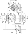
図1は、本発明の実施の形態に係る車両の制御装置1の構成を示すブロック図である。車両の制御装置1は、四輪自動車に搭載され、四輪自動車のブレーキアシスト制御を司る装置である。車両の制御装置1は、障害物センサ2、アクセルペダルセンサ3、車速センサ4、ブレーキペダルセンサ5、ECU(Electronic Control Unit)6、ブレーキアクチュエータ7、及びスロットル弁8を備える。
FIG. 1 is a block diagram showing a configuration of a
障害物センサ2は、例えば、レーザレーダ21及びソナー22で構成される。レーザレーダ21は、例えば、自車両のフロントグリルに設けられ、自車両の前方の所定の角度範囲を走査するようにレーザビームを照射し、反射したレーザビームを受光することによって、前方障害物の有無を検出すると共に、自車両から前方障害物までの距離を検出する。ソナー22は、例えば、自車両のフロントグリルに設けられ、自車両の前方に音波を照射し、反射した音波を受信することによって、前方障害物の有無を検出すると共に、自車両から前方障害物までの距離を検出する。ここで、前方障害物とは、自車両に対して進行方向に沿って直ぐ前方にある、停止中の車両、走行中の車両、又は車両以外の物体が該当する。
The
レーザレーダ21は、ソナー22に比べて長距離に位置する障害物を検出することができるが、障害物が検出可能な自車両の車速(自車速)の下限値がソナー22より大きいという特性を持つ。例えば、障害物が検出可能な自車速の下限値は、レーザレーダ21が4km/hであるのに対して、ソナーは2km/hである。
The
本実施の形態では、PTC制御部62は、ソナー22の測定データから前方障害物に関する情報を取得し、AEB制御部61は、レーザレーダ21の測定データから前方障害物に関する情報を取得する。但し、これは一例であり、PTC制御部62は、レーザレーダ21の測定データを用いて前方障害物に関する情報を取得してもよいし、AEB制御部61は、ソナー22の測定データ用いて前方障害物に関する情報を取得してもよい。ここで、前方障害物に関する情報には、例えば、前方障害物の有無を示す情報と、前方障害物までの距離を示す情報が含まれる。
In the present embodiment, the
アクセルペダルセンサ3(アクセル操作センサの一例)は、例えば、抵抗体の上を接点が摺動するポテンショ式の角度センサで構成され、アクセルペダルの踏みこみ量を検出して電気信号に変換してECU6に出力する。本実施の形態では、アクセルペダルセンサ3は、アクセルペダルの最大踏みこみ量を100としたときの実際の踏み込み量の割合によってアクセルペダルの踏みこみ量を表す。
The accelerator pedal sensor 3 (an example of an accelerator operation sensor) is composed of, for example, a potentiometer-type angle sensor in which contacts slide on a resistor, detects the amount of depression of the accelerator pedal, and converts it into an electric signal. Output to
車速センサ4は、例えば、車輪速センサで構成され、自車両の車速を検出する。ここで、車輪速センサは、例えば、ブレーキドラムなどの回転部分に設けられた歯車状のロータと、ロータに対して一定の隙間を設けて配置され、コイル及び磁極等で構成されたセンシング部とを備え、ロータの回転によりコイルに発生する交流電圧に基づいて、車輪の回転速度を検出する。 The vehicle speed sensor 4 is composed of, for example, a wheel speed sensor, and detects the vehicle speed of the own vehicle. Here, the wheel speed sensor includes, for example, a gear-shaped rotor provided in a rotating portion such as a brake drum, and a sensing unit configured with a coil, magnetic poles, etc., arranged with a certain gap between the rotors. The wheel rotation speed is detected based on the AC voltage generated in the coil due to the rotation of the rotor.
ブレーキペダルセンサ5(ブレーキ操作センサの一例)は、例えば、抵抗体の上を接点が摺動するポテンショ式の角度センサで構成され、ブレーキペダルの踏みこみ量を検出して電気信号に変換してECU6に出力する。本実施の形態では、ブレーキペダルセンサ5は、ブレーキペダルの最大踏みこみ量を100としたときの実際の踏み込み量の割合によってブレーキペダルの踏みこみ量を表す。
The brake pedal sensor 5 (an example of a brake operation sensor) is composed of, for example, a potential angle sensor in which contacts slide on a resistor, detects the amount of depression of the brake pedal, and converts it into an electric signal. Output to
ECU6は、CPU等のプロセッサと、ROM及びRAM等のメモリとを備えるコンピュータで構成され、車両の制御装置1の全体制御を司る。本実施の形態では、ECU6は、AEB(Autonomous Emergency Braking)制御部61、PTC(Pre-collision Throttle Control)制御部62、及び調停部63の機能を備えている。AEB制御部61、PTC制御部62、及び調停部63は、それぞれ、ECU6のプロセッサが所定の制御プログラムを実行することで実現される。但し、これは一例であり、AEB制御部61、PTC制御部62、及び調停部63は、それぞれ、異なるコンピュータで構成されてもよい。
The
AEB制御部61(緊急自動ブレーキ制御部の一例)は、レーザレーダ21により前方障害物が検出された場合、AEB(第1自動ブレーキの一例)を作動する。また、AEB制御部61は、アクセルペダルセンサ3により、第1操作量以上のアクセル操作が検出されたことを停止条件として、AEBの作動を停止する。AEBは、緊急時に自動ブレーキを作動させて衝突時の被害を軽減する自動ブレーキである。第1操作量としては、ドライバーが加速の意思を示したとみなせるアクセルペダルの踏み込み量が採用され、本実施の形態では、50%が採用される。但し、これは一例であり、第1操作量は、ドライバーが加速の意思を示したとみなせる値であれば、50%以外の値が採用されてもよい。
The AEB control unit 61 (an example of an emergency automatic brake control unit) operates the AEB (an example of the first automatic brake) when a forward obstacle is detected by the
PTC制御部62(誤発進抑制制御部の一例)は、車速センサ4により検出された車速が所定の車速範囲内にある場合において、前方障害物が検出され、且つ、第1操作量より小さい第2操作量以上のアクセル操作が検出された場合、自車両のエンジン出力を低減し、且つ、PTC自動ブレーキ(第2自動ブレーキの一例)を行うPTCを作動する。PTCは、アクセルペダルの誤操作によって自車両が急発進した場合の衝突時の被害を軽減する急発進抑制制御である。以下、PTCにおいて、エンジン出力を低減させることを「PTC低減制御」と記述する。なお、PTC低減制御を作動させる場合、PTC制御部62は、スロットル弁8を閉じでエンジンへの燃料の供給を停止させることで、エンジン出力を低減すればよい。
The PTC control unit 62 (an example of an erroneous start suppression control unit) detects an obstacle ahead when the vehicle speed detected by the vehicle speed sensor 4 is within a predetermined vehicle speed range, and is smaller than the first operation amount. When an accelerator operation of two or more operation amounts is detected, the PTC that reduces the engine output of the own vehicle and performs PTC automatic braking (an example of the second automatic braking) is operated. PTC is a sudden start suppression control that reduces damage in the event of a collision when the own vehicle suddenly starts due to an erroneous operation of the accelerator pedal. Hereinafter, in PTC, reducing the engine output is described as "PTC reduction control". When operating the PTC reduction control, the
ここで、所定の車速範囲としては、図2のグラフPTC_BCに示されるように、2km/hから15km/hまでの車速範囲が採用できる。但し、これは、一例であり、所定の車速範囲は、アクセルペダルの誤操作による急発進を自動ブレーキで抑制する必要がある車速範囲であれば、他の車速範囲が採用されてもよい。また、第2操作量としては、例えば、ドライバーがアクセルペダルを誤操作した場合に想定されるアクセルペダルの踏み込み量の最小値が採用でき、本実施の形態では、10%が採用される。但し、これは一例であり、第2操作量としては、第1操作量より小さい範囲内において10%より大きな値、或いは、10%よりも小さな値が採用できる。 Here, as the predetermined vehicle speed range, as shown in the graph PTC_BC of FIG. 2, a vehicle speed range from 2 km / h to 15 km / h can be adopted. However, this is only an example, and as long as the predetermined vehicle speed range is a vehicle speed range in which it is necessary to suppress sudden start due to an erroneous operation of the accelerator pedal by automatic braking, another vehicle speed range may be adopted. Further, as the second operation amount, for example, the minimum value of the depression amount of the accelerator pedal assumed when the driver erroneously operates the accelerator pedal can be adopted, and in the present embodiment, 10% is adopted. However, this is an example, and as the second operation amount, a value larger than 10% or a value smaller than 10% can be adopted within a range smaller than the first operation amount.
図1を参照し、調停部63は、AEBの停止条件とPTC自動ブレーキの作動条件とが競合した場合、PTC自動ブレーキを優先させる。
With reference to FIG. 1, the
ブレーキアクチュエータ7は、ECU6から出力されるブレーキコマンドにしたがって、ブレーキコマンドが示す制動力をブレーキ(図略)に発生させる。ここで、ブレーキアクチュエータ7は、例えば、ブレーキコマンドが示す制動力に対応する油圧でブレーキを作動させればよい。スロットル弁8は、ECU6のコマンドにしたがって、エンジン(図略)への吸気量を調節する。ブレーキは、例えば、ディスク式又はドラム式のブレーキで構成され、車両の車輪を制動する。
The brake actuator 7 generates a braking force indicated by the brake command in the brake (not shown) according to the brake command output from the
図2は、PTCとAEBとの作動タイミングの一例を示すグラフである。図2において、縦軸は前方障害物との距離(m)を示し、横軸は自車速(km/h)を示している。 FIG. 2 is a graph showing an example of the operation timing of the PTC and the AEB. In FIG. 2, the vertical axis indicates the distance (m) from the obstacle in front, and the horizontal axis indicates the own vehicle speed (km / h).
図2において、四角形の点でプロットされたグラフはAEBの作動タイミングを示すグラフ(以下、「グラフAEB」と記述する。)であり、AEB制御部61は、自車速と前方障害物までの距離とがグラフAEBよりも下側の領域に位置する場合、AEBを作動する。
In FIG. 2, the graph plotted by the points of the rectangle is a graph showing the operation timing of the AEB (hereinafter, referred to as “graph AEB”), and the
グラフAEBは、自車速が0km/hから4km/hまでの車速範囲では前方障害物までの距離を0(m)に維持している。したがって、AEB制御部61は、この車速範囲ではAEBを作動させない。また、グラフAEBは、自車速が4km/h(第2下限車速の一例)を超えると、自車速が増大するにつれて、前方障害物までの距離が、下側に緩やかに湾曲したカーブに沿って増大している。したがって、AEB制御部61は、自車速が4km/h以上になると、自車速が減少するにつれて、より近くに前方障害物が位置していなければ、AEBを作動さない。
Graph AEB maintains the distance to the obstacle ahead at 0 (m) in the vehicle speed range from 0 km / h to 4 km / h. Therefore, the
図2において、菱形の点がプロットされたグラフはPTC自動ブレーキの作動タイミングを示すグラフ(以下、「グラフPTC_BC」と記述する。)である。PTC制御部62は、前方障害物までの距離と自車速とがグラフPTC_BCの下側の領域に位置する場合、PTC自動ブレーキを作動させる。
In FIG. 2, the graph in which the diamond-shaped points are plotted is a graph showing the operation timing of the PTC automatic brake (hereinafter, referred to as “graph PTC_BC”). The
グラフPTC_BCは、自車速が0km/hから2km/h(第1下限車速の一例)までの車速範囲では前方障害物までの距離を0mに維持している。したがって、PTC制御部62は、この車速範囲ではPTC自動ブレーキを作動させない。また、グラフPTC_BCは、自車速が2km/hから15km/hまでの車速範囲では、前方障害物までの距離が4mを上限として、自車速が増大するにつれて前方障害物までの距離が増大している。したがって、PTC制御部62は、自車速が2km/hから、前方車両までの距離が4mに到達する13km/hまでの車速範囲では、自車速が減少するにつれて、より近くに前方障害物が位置していなければ、PTC自動ブレーキを作動させない。また、PTC制御部62は、自車速が13km/hから15km/hまでの車速範囲では、前方障害物までの距離が4m以下になるとPTC自動ブレーキを作動する。
Graph PTC_BC maintains the distance to the obstacle ahead at 0 m in the vehicle speed range from 0 km / h to 2 km / h (an example of the first lower limit vehicle speed). Therefore, the
図2において、バツ印の点がプロットされたグラフはPTC低減制御の作動タイミングを示すグラフ(以下、「グラフPTC_TC」と記述する。)である。PTC制御部62は、前方障害物までの距離と自車速とがグラフPTC_TCの下側の領域に位置する場合、PTC低減制御を作動させる。
In FIG. 2, the graph in which the points marked with crosses are plotted is a graph showing the operation timing of the PTC reduction control (hereinafter, referred to as “graph PTC_TC”). The
グラフPTC_TCは、自車速が0km/hから15km/hまでの車速範囲では、前方障害物までの距離を4mに維持している。したがって、PTC制御部62は、自車速が15km/h以下の車速範囲では、前方障害物までの距離が4m以下になるとPTC低減制御を作動させる。
Graph PTC_TC maintains the distance to the obstacle ahead at 4 m in the vehicle speed range from 0 km / h to 15 km / h. Therefore, the
図2に示すように、本実施の形態では、自車速が2km/hより大きくなると、前方障害物までの距離に応じたPTC自動ブレーキが作動され、自車速が4km/hより大きくなると、PTC自動ブレーキに加えて、AEBも作動条件を満たし、両自動ブレーキが競合することになる。PTC自動ブレーキとAEBとが共に作動条件を満たす場合に、AEBのみを作動させる態様が採用されると、アクセル踏み込み量が50%より大きくなってAEBが停止されると、2km/hから15km/hの車速範囲において、車両に対して自動ブレーキが全く作動されくなる。 As shown in FIG. 2, in the present embodiment, when the own vehicle speed is higher than 2 km / h, the PTC automatic brake is activated according to the distance to the obstacle ahead, and when the own vehicle speed is higher than 4 km / h, the PTC is activated. In addition to the automatic braking, the AEB also meets the operating conditions, and both automatic braking will compete. When both the PTC automatic brake and the AEB satisfy the operating conditions and the mode of operating only the AEB is adopted, when the accelerator depression amount becomes larger than 50% and the AEB is stopped, 2 km / h to 15 km / h / In the vehicle speed range of h, the automatic brake is not activated for the vehicle at all.
そこで、本実施の形態では、調停部63は、PTC自動ブレーキとAEBとが共に作動条件を満たした場合、PTC自動ブレーキを優先する態様を採用した。これにより、4km/hから15km/hまでの車速範囲において、AEBが停止条件を満たしても、PTC自動ブレーキが作動を継続するので、この場面において、車両に対して自動ブレーキが全く作動しなくなる事態を回避することができる。但し、この場面では、自動ブレーキが全く作動されなくても、PTC低減制御が作動されるので、車両に対する制動力が全く作用しないわけではない。
Therefore, in the present embodiment, the
ここで、AEB制御部61とPTC制御部62とは、それぞれ、独立して駆動している。そして、AEB制御部61は、AEBを作動させる場合、予め定められた目標減速度を設定し、車両の減速度を目標減速度にするためのブレーキコマンドを生成する。同様に、PTC制御部62も、PTC自動ブレーキを作動させる場合、予め定められた目標減速度を設定し、車両の減速度を目標減速度にするためのブレーキコマンドを生成する。
Here, the
したがって、調停部63は、AEBとPTC自動ブレーキとが共に作動条件を満たす場合、PTC制御部62に対して作動指示を出力し、AEB制御部61に対して非作動指示を出力すればよい。
Therefore, when both the AEB and the PTC automatic brake satisfy the operation condition, the
なお、AEBの目標減速度とPTC自動ブレーキの目標減速度とは、例えば、自車速に拘わらず一定の値が採用されてもよいし、自車速が大きくなるにつれて段階的又は連続的に大きくなる値が採用されてもよい。 The target deceleration of the AEB and the target deceleration of the PTC automatic brake may be, for example, a constant value regardless of the own vehicle speed, and gradually or continuously increase as the own vehicle speed increases. The value may be adopted.
図2において、自車速が15km/hより大きくなると、PTC制御部62は、PTC自動ブレーキとPTC低減制御との両方の作動を停止させる。そのため、自車速が15km/hより大きい車速範囲では、前方障害物との距離に応じてAEBが作動することになる。これにより、自車速が15km/hより大きく、急発進を抑制する必要がない場面においてPTCが作動されることを防止することができ、操作性を高めることができる。
In FIG. 2, when the own vehicle speed becomes higher than 15 km / h, the
また、図2において、PTC自動ブレーキが作動する車速範囲の下限値が2km/hに設定されている。これは、PTC制御部62はソナー22の測定データを用いてPTCの作動の有無を判定しており、ソナー22が障害物を検出可能な自車速の下限値が2km/hであるからである。また、AEBが作動する車速範囲の下限値が4km/hに設定されている。これは、AEB制御部61はレーザレーダ21の測定データを用いてAEBの作動の有無を判定しており、レーザレーダ21が障害物を検出可能な自車速の下限値が4km/hであるからである。
Further, in FIG. 2, the lower limit value of the vehicle speed range in which the PTC automatic brake operates is set to 2 km / h. This is because the
また、図2において、PTC自動ブレーキとPTC減速制御とが作動する車速範囲の上限値が15km/hに設定されている。これは、アクセルペダルの誤踏み込みによる急発進が発生する場面の自車速の上限値は、およそ15km/h程度と考えられているからである。 Further, in FIG. 2, the upper limit of the vehicle speed range in which the PTC automatic braking and the PTC deceleration control are operated is set to 15 km / h. This is because it is considered that the upper limit of the own vehicle speed in a scene where a sudden start occurs due to an erroneous depression of the accelerator pedal is about 15 km / h.
図3は、図1に示すPTC制御部62の処理の一例を示すフローチャートである。S301では、PTC制御部62は、ソナー22の測定データから、ソナー22が前方障害物を検出したか否かを判定する。ソナー22が前方障害物を検出した場合(S301でYES)、PTC制御部62は、ソナー22の測定データからその前方障害物までの距離を取得し、その距離が4mより大きいか否かを判定する(S302)。一方、ソナー22が前方障害物を検出していない場合(S301でNO)、処理はS312に進む。
FIG. 3 is a flowchart showing an example of the processing of the
前方障害物までの距離が4m以上である場合(S302でNO)、処理はS312に進み、前方障害物までの距離が4mより小さい場合(S302でYES)、処理はS303に進む。 If the distance to the front obstacle is 4 m or more (NO in S302), the process proceeds to S312, and if the distance to the front obstacle is less than 4 m (YES in S302), the process proceeds to S303.
S303では、PTC制御部62は、アクセルペダルセンサ3が検出したアクセルペダルの踏み込み量が10%より大きいか否かを判定する。S303で、アクセルペダルの踏み込み量が10%より大きい場合(S303でYES)、処理はS304に進み、アクセルペダルの踏み込み量が10%以下の場合(S303でNO)、処理はS312に進む。
In S303, the
S304では、PTC制御部62は、車速センサ4が検出した自車速が2km/hより小さいか否かを判定する。S304で、自車速が2km/hより小さい場合(S304でYES)、処理はS305に進み、自車速が2km/h以上の場合(S304でNO)、処理はS308に進む。
In S304, the
S305では、PTC制御部62は、PTCのフラグF(PTC)が0又は2である場合(S305でYES)、PTC減速制御を作動させるために、フラグF(PTC)を「1」に設定する(S306)。ここで、フラグF(PTC)は、「0」、「1」、又は「2」の値をとり、「0」はPTCの非作動を示し、「1」はPTC減速制御の作動を示し、「2」はPTC減速制御及びPTC自動ブレーキの作動を示す。以下、PTC減速制御のみが作動するPTCを単に「PTC減速制御」と記載し、PTC減速制御及びPTC自動ブレーキが作動するPTCを「自動ブレーキを伴うPTC」と記述する。
In S305, the
すなわち、S306では、前方障害物までの距離と自車速とがグラフPTC_TCの下側の領域に位置するので、PTC減速制御を作動させるために、フラグF(PTC)が「1」に設定されるのである。 That is, in S306, since the distance to the obstacle ahead and the own vehicle speed are located in the lower region of the graph PTC_TC, the flag F (PTC) is set to "1" in order to activate the PTC deceleration control. It is.
S305において、フラグF(PTC)が「1」であり(S305でNO)、PTC減速制御が作動中であれば、処理はS307に進む。 In S305, if the flag F (PTC) is "1" (NO in S305) and the PTC deceleration control is in operation, the process proceeds to S307.
S308では、PTC制御部62は、自車速が2km/hから15km/hまでの車速範囲にあるか否かを判定する。自車速が2km/hから15km/hまでの車速範囲にあれば(S308でYES)、処理はS309に進み、自車速が2km/hから15km/hまでの車速範囲になければ(S308でNO)、処理はS312に進む。
In S308, the
S309では、PTC制御部62は、S302で取得した前方障害物までの距離がグラフPTC_BC(図2)の下側の領域に位置するか否かを判定することにより、当該距離がPTC自動ブレーキの作動条件を満たすか否かを判定する。
In S309, the
当該距離がPTC自動ブレーキの作動条件を満たす場合(S309でYES)、処理はS310に進み、当該距離がPTC自動ブレーキの作動条件を満たさない場合(S309でNO)、処理はS312に進む。 If the distance satisfies the operating condition of the PTC automatic brake (YES in S309), the process proceeds to S310, and if the distance does not satisfy the operating condition of the PTC automatic brake (NO in S309), the process proceeds to S312.
S310では、フラグF(PTC)が「0」又は「1」であり(S310でYES)、自動ブレーキを伴うPTCが作動中でなければ、PTC制御部62は、自動ブレーキを伴うPTCを作動させるために、フラグF(PTC)を「2」に設定する(S311)。一方、フラグF(PTC)が「2」であり(S310でNO)、自動ブレーキを伴うPTCが作動中であれば、処理をS307に進める。
In S310, if the flag F (PTC) is "0" or "1" (YES in S310) and the PTC with automatic braking is not in operation, the
S307では、PTC制御部62は、アクセルペダルセンサ3の測定データから、アクセルペダルの操作が連続して3回行われたか、又はブレーキペダルセンサ5の測定データから、ブレーキペダルの操作が行われた否かを判定する。アクセルペダルの操作が連続して3回行われた場合、ドライバーは加速の意思を示しており、PTCが不要である。また、ブレーキペダルが操作された場合、ドライバーのブレーキペダルの操作によって、前方障害物との衝突の軽減を図ることができる。そこで、本フローではS307の処理を設けた。
In S307, the
S307で、アクセルペダルの操作が連続して3回行われた、又は、ブレーキペダルの操作が行われた場合(S307でYES)、PTCの作動を停止させるために、処理はS312に進む。一方、S307で、アクセルペダルの操作が連続して3回行われておらず、且つ、ブレーキペダルの操作も行われていない場合(S307でNO)、PTCの作動を継続するために、処理はS301に戻る。 If the accelerator pedal is operated three times in succession in S307, or the brake pedal is operated (YES in S307), the process proceeds to S312 in order to stop the operation of the PTC. On the other hand, in S307, when the accelerator pedal is not operated three times in a row and the brake pedal is not operated (NO in S307), the process is performed in order to continue the operation of the PTC. Return to S301.
S312では、フラグF(PTC)が「1」又は「2」であり(S312でYES)、PTCが作動中であれば、PTC制御部62は、PTCを非作動にするために、フラグF(PTC)を「0」に設定し(S313)、処理をS301に戻す。一方、S312で、フラグF(PTC)が「0」であり(S312でNO)、PTCが非作動であれば、処理はS301に戻る。
In S312, if the flag F (PTC) is "1" or "2" (YES in S312) and the PTC is in operation, the
このように、PTC制御部62は、図3のフローを繰り返し、PTCの作動の有無を判定する。
In this way, the
図4は、図1に示すAEB制御部61の処理の一例を示すフローチャートである。S401では、AEB制御部61は、レーザレーダ21の測定データから、レーザレーダが前方障害物を検出したか否かを判定する。レーザレーダ21が前方障害物を検出した場合(S401でYES)、AEB制御部61は、車速センサ4の測定データから自車速を取得し、自車速が2km/hより大きいか否かを判定する(S402)。一方、レーザレーダ21が前方障害物を検出していない場合(S401でNO)、処理はS407に進む。
FIG. 4 is a flowchart showing an example of the processing of the
自車速が2km/hより大きい場合(S402でYES)、処理はS403に進み、自車速が2km/h以下の場合(S402でNO)、処理はS407に進む。 If the vehicle speed is higher than 2 km / h (YES in S402), the process proceeds to S403, and if the vehicle speed is 2 km / h or less (NO in S402), the process proceeds to S407.
S403では、AEB制御部61は、レーザレーダ21の測定データから前方障害物までの距離を取得し、その距離がグラフAEB(図2)の下側の領域に位置するか否かを判定することにより、当該距離がAEBの作動条件を満たすか否かを判定する。
In S403, the
当該距離がAEBの作動条件を満たす場合(S403でYES)、処理はS404に進み、当該距離がAEBの作動条件を満たしていない場合(S403でNO)、処理はS407に進む。 If the distance meets the AEB operating condition (YES in S403), the process proceeds to S404, and if the distance does not meet the AEB operating condition (NO in S403), the process proceeds to S407.
S404では、AEB制御部61は、AEBのフラグF(AEB)が「0」である場合(S404でYES)、AEBを作動させるために、フラグF(AEB)を「1」に設定する(S405)。ここで、フラグF(AEB)は、「0」又は「1」の値をとり、「0」はAEBの非作動を示し、「1」はAEBの作動を示す。
In S404, the
S404でフラグF(AEB)が「1」であり(S404でNO)、AEBが作動中であれば、処理はS406に進む。 If the flag F (AEB) is "1" in S404 (NO in S404) and the AEB is in operation, the process proceeds to S406.
S406では、AEB制御部61は、アクセルペダルセンサ3の測定データからアクセルペダルの踏み込み量を取得し、その踏み込み量が50%以上の場合(S406でYES)、ドライバーは加速の意思を示しており、AEBの停止条件を満たすため、処理をS407に進める。一方、アクセルペダルの踏み込み量が50%より小さい場合(S406でNO)、ドライバーは加速の意思を示していないため、処理はS401に戻る。
In S406, the
S407では、フラグF(AEB)が「1」であれば(S407でYES)、AEB制御部61は、AEBを非作動にするために、フラグF(AEB)を「0」に設定する(S408)。一方、フラグF(AEB)が「0」であり(S407でNO)、AEBが非作動であれば、処理はS401に戻る。
In S407, if the flag F (AEB) is "1" (YES in S407), the
このように、AEB制御部61は、図4のフローを繰り返し、AEBの作動の有無を判定する。
In this way, the
図5は、図1に示す調停部63の処理の一例を示すフローチャートである。調停部63は、フラグF(PTC)が2である場合(S501でYES)、フラグF(AEB)の値に拘わらず、自動ブレーキを伴うPTCの作動指示を、PTC制御部62に出力する(S502)。この場合、調停部63はAEB制御部61に対して、非作動指示を出力する。これにより、PTC制御部62からブレーキアクチュエータ7にブレーキコマンドが出力され、PTC制御部62の制御の下、自動ブレーキを伴うPTCが作動される。
FIG. 5 is a flowchart showing an example of the processing of the
すなわち、S501、S502の処理は、PTC自動ブレーキとAEBとの両方が作動条件を満たしたとしても、PTC自動ブレーキを優先的に作動させる処理になっている。これにより、4km/hから15km/hまでの車速範囲において、アクセルペダルの踏み込み量が50%を超えてAEBの停止条件が満たされたとしても、自動ブレーキが非作動になることを防止できる。 That is, the process of S501 and S502 is a process of preferentially operating the PTC automatic brake even if both the PTC automatic brake and the AEB satisfy the operating conditions. As a result, in the vehicle speed range from 4 km / h to 15 km / h, even if the accelerator pedal depression amount exceeds 50% and the AEB stop condition is satisfied, it is possible to prevent the automatic brake from being deactivated.
フラグF(PTC)が「2」でない場合(S501でNO)、調停部63は、フラグF(PTC)が「1」であるか否かを判定する(S503)。フラグF(PTC)が「1」の場合(S503でYES)、フラグF(AEB)が「1」であれば(S504でYES)、すなわち、フラグF(PTC)及びフラグF(AEB)が共に1である場合、調停部63は、PTC低減制御の作動指示をPTC制御部62に出力し、且つ、AEBの作動指示をAEB制御部61に出力する。これにより、AEB制御部61からブレーキアクチュエータ7にブレーキコマンドが出力されると共に、PTC制御部62によりPTC低減制御が作動される。
When the flag F (PTC) is not "2" (NO in S501), the
S504でフラグF(AEB)が「0」の場合(S504でNO)、すなわち、フラグF(PTC)が「1」、且つ、フラグF(AEB)が「0」の場合、調停部63は、PTC低減制御の作動指示をPTC制御部62に出力する(S506)。これにより、PTC低減制御のみが作動される。
When the flag F (AEB) is "0" in S504 (NO in S504), that is, when the flag F (PTC) is "1" and the flag F (AEB) is "0", the
S503でフラグF(PTC)が「0」の場合(S503でNO)、フラグF(AEB)が「1」であれば(S507でYES)、すなわち、フラグF(PTC)が「0」、且つ、フラグF(AEB)が「1」の場合、調停部63は、AEBの作動指示をAEB制御部61に出力する(S508)。このとき、調停部63は、PTCの非作動指示をPTC制御部62に出力する。これにより、AEBのみが作動される。
When the flag F (PTC) is "0" in S503 (NO in S503), when the flag F (AEB) is "1" (YES in S507), that is, the flag F (PTC) is "0" and When the flag F (AEB) is "1", the
フラグF(AEB)が「0」の場合(S507でNO)、すなわち、フラグF(PTC)が「0」、且つ、フラグF(AEB)が「0」の場合、調停部63は、AEBの非作動指示をAEB制御部61に出力し、且つ、PTCの非作動指示をPTC制御部62に出力する(S509)。これにより、AEB及びPTCの作動が停止される。
When the flag F (AEB) is "0" (NO in S507), that is, when the flag F (PTC) is "0" and the flag F (AEB) is "0", the
S502、S505、S506、S508、S509の処理が終了すると、処理はS501に戻る。このように、調停部63は、図5のフローを繰り返し、AEBとPTC自動ブレーキとの調停を行う。
When the processing of S502, S505, S506, S508, and S509 is completed, the processing returns to S501. In this way, the
このように、本実施の形態によれば、PTC自動ブレーキの作動中に、第1操作量以上のアクセル踏み込み量が検出されてAEBが停止条件を満たしたとしても、PTC自動ブレーキは継続される。その結果、2km/hから4km/hの車速範囲において、自動ブレーキが全く作動されない事態を回避することができる。 As described above, according to the present embodiment, even if the accelerator depression amount equal to or larger than the first operation amount is detected and the AEB satisfies the stop condition during the operation of the PTC automatic brake, the PTC automatic brake is continued. .. As a result, it is possible to avoid a situation in which the automatic brake is not operated at all in the vehicle speed range of 2 km / h to 4 km / h.
なお、本発明は以下の変形例が採用できる。 The following modifications can be adopted in the present invention.
(1)図3のS307では、アクセルペダルの操作が連続して3回検出された場合にYESと判定されているが、これは一例であり、2回又は4回以上検出された場合にYESと判定されてもよい。 (1) In S307 of FIG. 3, it is determined as YES when the accelerator pedal operation is detected three times in succession, but this is an example, and YES when it is detected twice or four times or more. May be determined.
(2)図2では、PTC自動ブレーキが作動される車速範囲の下限値はAEBが作動される車速範囲の下限値よりも小さく設定されているが、この関係は逆であってもよいし、この下限値は同じであってもよい。 (2) In FIG. 2, the lower limit of the vehicle speed range in which the PTC automatic brake is operated is set smaller than the lower limit of the vehicle speed range in which the AEB is operated, but this relationship may be reversed. This lower limit may be the same.
(3)図2において、PTC自動ブレーキが作動される車速範囲の上限値と、PTC減速制御が作動される車速範囲の上限値とは同じ15km/hに設定されているが、これは一例であり、両上限値は異なる値に設定されてもよい。 (3) In FIG. 2, the upper limit of the vehicle speed range in which the PTC automatic brake is operated and the upper limit of the vehicle speed range in which the PTC deceleration control is operated are set to the same 15 km / h, but this is an example. Yes, both upper limits may be set to different values.
(4)図2において、グラフAEBはグラフPTC_BCよりも全体的に上側に位置しているが、この関係は逆であってもよい。 (4) In FIG. 2, the graph AEB is located above the graph PTC_BC as a whole, but this relationship may be reversed.
1 車両の制御装置
2 障害物センサ
3 アクセルペダルセンサ
4 車速センサ
5 ブレーキペダルセンサ
6 ECU
7 ブレーキアクチュエータ
8 スロットル弁
21 レーザレーダ
22 ソナー
61 AEB制御部
62 PTC制御部
63 調停部
1
7
Claims (5)
前記自車両の車速を検出する車速センサと、
アクセル操作を検出するアクセル操作センサと、
前記前方障害物が検出された場合、第1自動ブレーキを作動し、ドライバーが加速の意思を示したとみなせる第1操作量以上の前記アクセル操作が検出されたことを停止条件として、第1自動ブレーキの作動を停止する緊急自動ブレーキ制御部と、
前記検出された車速が所定の車速範囲内にある場合において、前記前方障害物が検出され、且つ、前記ドライバーがアクセルペダルを誤操作した場合に想定される前記アクセルペダルの操作量であって前記第1操作量より小さい第2操作量以上の前記アクセル操作が検出された場合、前記自車両のエンジン出力を低減し、且つ、第2自動ブレーキを行う誤発進抑制制御を作動する誤発進抑制制御部と、
前記第1自動ブレーキの前記停止条件と前記第2自動ブレーキの作動条件とが競合した場合、前記第2自動ブレーキを優先させる調停部とを備える車両の制御装置。 An obstacle sensor that detects obstacles in front of your vehicle,
The vehicle speed sensor that detects the vehicle speed of the own vehicle and
Accelerator operation sensor that detects accelerator operation and
When the forward obstacle is detected, the first automatic brake is activated, and the first automatic brake is set on the condition that the accelerator operation of the first operation amount or more that can be regarded as indicating the driver's intention to accelerate is detected. Emergency automatic brake control unit that stops the operation of
The operation amount of the accelerator pedal, which is assumed when the detected vehicle speed is within a predetermined vehicle speed range, the front obstacle is detected, and the driver erroneously operates the accelerator pedal, is the first. When the accelerator operation equal to or greater than the second operation amount smaller than the first operation amount is detected, the erroneous start suppression control unit that reduces the engine output of the own vehicle and activates the erroneous start suppression control that performs the second automatic braking. When,
A vehicle control device including an arbitration unit that gives priority to the second automatic brake when the stop condition of the first automatic brake and the operating condition of the second automatic brake conflict with each other.
前記誤発進抑制制御部は、更に、前記検出された距離が所定距離以下の場合、前記誤発進抑制制御を作動する請求項1又は2記載の車両の制御装置。 The obstacle sensor further detects the distance between the front obstacle and the own vehicle, and further detects the distance.
The vehicle control device according to claim 1 or 2, wherein the false start suppression control unit further activates the false start suppression control when the detected distance is equal to or less than a predetermined distance.
前記誤発進抑制制御部は、前記アクセル操作が連続してN(Nは2以上の整数)回検出された場合、又は前記ブレーキ操作が検出された場合、前記誤発進抑制制御の作動を停止する請求項1~3のいずれかに記載の車両の制御装置。 It also has a brake operation sensor that detects the brake operation.
The erroneous start suppression control unit stops the operation of the erroneous start suppression control when the accelerator operation is continuously detected N (N is an integer of 2 or more) times, or when the brake operation is detected. The vehicle control device according to any one of claims 1 to 3.
Priority Applications (5)
| Application Number | Priority Date | Filing Date | Title |
|---|---|---|---|
| JP2018025813A JP7087432B2 (en) | 2018-02-16 | 2018-02-16 | Vehicle control unit |
| US16/967,583 US20210237720A1 (en) | 2018-02-16 | 2019-01-29 | Vehicle control device |
| PCT/JP2019/002833 WO2019159677A1 (en) | 2018-02-16 | 2019-01-29 | Vehicle control device |
| EP19754532.0A EP3738848A4 (en) | 2018-02-16 | 2019-01-29 | Vehicle control device |
| CN201980012623.1A CN111699120A (en) | 2018-02-16 | 2019-01-29 | Vehicle control device |
Applications Claiming Priority (1)
| Application Number | Priority Date | Filing Date | Title |
|---|---|---|---|
| JP2018025813A JP7087432B2 (en) | 2018-02-16 | 2018-02-16 | Vehicle control unit |
Publications (2)
| Publication Number | Publication Date |
|---|---|
| JP2019142266A JP2019142266A (en) | 2019-08-29 |
| JP7087432B2 true JP7087432B2 (en) | 2022-06-21 |
Family
ID=67619940
Family Applications (1)
| Application Number | Title | Priority Date | Filing Date |
|---|---|---|---|
| JP2018025813A Active JP7087432B2 (en) | 2018-02-16 | 2018-02-16 | Vehicle control unit |
Country Status (5)
| Country | Link |
|---|---|
| US (1) | US20210237720A1 (en) |
| EP (1) | EP3738848A4 (en) |
| JP (1) | JP7087432B2 (en) |
| CN (1) | CN111699120A (en) |
| WO (1) | WO2019159677A1 (en) |
Families Citing this family (3)
| Publication number | Priority date | Publication date | Assignee | Title |
|---|---|---|---|---|
| JP7084443B2 (en) * | 2020-03-19 | 2022-06-14 | 本田技研工業株式会社 | Vehicle control unit and vehicle |
| US11433915B2 (en) * | 2020-08-28 | 2022-09-06 | Toyota Research Institute, Inc. | Determining an action to be performed by a vehicle in response to conflicting input signals |
| JP2024057467A (en) * | 2022-10-12 | 2024-04-24 | スズキ株式会社 | Vehicle control device |
Citations (6)
| Publication number | Priority date | Publication date | Assignee | Title |
|---|---|---|---|---|
| JP2000264097A (en) | 1999-03-12 | 2000-09-26 | Mazda Motor Corp | Control device for vehicle |
| JP2007296950A (en) | 2006-04-28 | 2007-11-15 | Advics:Kk | Drive support control device |
| JP2012153164A (en) | 2011-01-21 | 2012-08-16 | Denso Corp | In-vehicle system |
| JP2012179936A (en) | 2011-02-28 | 2012-09-20 | Denso Corp | Accelerator pedal wrong operation corresponding device and program for the same |
| JP2015036270A (en) | 2013-08-12 | 2015-02-23 | マツダ株式会社 | Braking device for vehicle |
| JP2016150711A (en) | 2015-02-19 | 2016-08-22 | 富士重工業株式会社 | Brake override system |
Family Cites Families (10)
| Publication number | Priority date | Publication date | Assignee | Title |
|---|---|---|---|---|
| US7866427B2 (en) * | 2008-07-08 | 2011-01-11 | GM Global Technology Operations LLC | Vehicle multi-stage integrated brake assist for a collision preparation system |
| JP4697486B2 (en) * | 2008-07-23 | 2011-06-08 | 株式会社デンソー | Automotive control system |
| DE102009057836B4 (en) * | 2009-12-10 | 2013-02-21 | Continental Teves Ag & Co. Ohg | Emergency braking assistance system to assist a driver of a vehicle when starting |
| JP5871572B2 (en) * | 2011-11-14 | 2016-03-01 | 富士重工業株式会社 | Vehicle output control device |
| JP2013129228A (en) * | 2011-12-20 | 2013-07-04 | Toyota Motor Corp | Vehicle control device |
| EP2927082B1 (en) * | 2012-11-27 | 2017-08-02 | Nissan Motor Co., Ltd | Vehicule acceleration suppression device and vehicle acceleration suppression method |
| JP6020338B2 (en) * | 2013-04-26 | 2016-11-02 | マツダ株式会社 | Vehicle control device |
| JP6166242B2 (en) * | 2014-11-28 | 2017-07-19 | 株式会社アドヴィックス | Collision avoidance device |
| JP6014185B2 (en) * | 2015-02-16 | 2016-10-25 | 本田技研工業株式会社 | Vehicle travel control device, vehicle travel control method, and vehicle travel control program |
| JP6772603B2 (en) * | 2016-07-08 | 2020-10-21 | 三菱自動車工業株式会社 | Vehicle false start suppression device |
-
2018
- 2018-02-16 JP JP2018025813A patent/JP7087432B2/en active Active
-
2019
- 2019-01-29 US US16/967,583 patent/US20210237720A1/en not_active Abandoned
- 2019-01-29 CN CN201980012623.1A patent/CN111699120A/en active Pending
- 2019-01-29 WO PCT/JP2019/002833 patent/WO2019159677A1/en unknown
- 2019-01-29 EP EP19754532.0A patent/EP3738848A4/en not_active Withdrawn
Patent Citations (6)
| Publication number | Priority date | Publication date | Assignee | Title |
|---|---|---|---|---|
| JP2000264097A (en) | 1999-03-12 | 2000-09-26 | Mazda Motor Corp | Control device for vehicle |
| JP2007296950A (en) | 2006-04-28 | 2007-11-15 | Advics:Kk | Drive support control device |
| JP2012153164A (en) | 2011-01-21 | 2012-08-16 | Denso Corp | In-vehicle system |
| JP2012179936A (en) | 2011-02-28 | 2012-09-20 | Denso Corp | Accelerator pedal wrong operation corresponding device and program for the same |
| JP2015036270A (en) | 2013-08-12 | 2015-02-23 | マツダ株式会社 | Braking device for vehicle |
| JP2016150711A (en) | 2015-02-19 | 2016-08-22 | 富士重工業株式会社 | Brake override system |
Also Published As
| Publication number | Publication date |
|---|---|
| EP3738848A4 (en) | 2021-03-17 |
| JP2019142266A (en) | 2019-08-29 |
| US20210237720A1 (en) | 2021-08-05 |
| WO2019159677A1 (en) | 2019-08-22 |
| CN111699120A (en) | 2020-09-22 |
| EP3738848A1 (en) | 2020-11-18 |
Similar Documents
| Publication | Publication Date | Title |
|---|---|---|
| WO2019159676A1 (en) | Vehicle control device | |
| JP6123873B2 (en) | Advanced driver support system for vehicle and control method thereof | |
| JP4172434B2 (en) | Inter-vehicle distance control device | |
| JP6809331B2 (en) | Vehicle control device | |
| JP6166242B2 (en) | Collision avoidance device | |
| JP6596772B2 (en) | Vehicle control device, vehicle control method, and program | |
| US8751134B2 (en) | Method and device for regulating the speed of a motor vehicle | |
| JP7087432B2 (en) | Vehicle control unit | |
| JP6300181B2 (en) | Vehicle control device | |
| JP7180077B2 (en) | vehicle controller | |
| JP7176415B2 (en) | Pre-collision control device | |
| JP6014185B2 (en) | Vehicle travel control device, vehicle travel control method, and vehicle travel control program | |
| JP7226348B2 (en) | Driving support device | |
| US11780430B2 (en) | Vehicle control device and control method | |
| JP2022024323A (en) | Collision avoidance support device | |
| CN114604238A (en) | Vehicle control device | |
| JP5994757B2 (en) | Vehicle control device | |
| JP6623422B2 (en) | Braking force control device and braking force control method | |
| JP6848537B2 (en) | Rear alarm device for vehicles | |
| JP2003306053A (en) | Vehicle travelling control system | |
| JP7188374B2 (en) | Vehicle braking assistance device | |
| JP2009248683A (en) | Following distance control device | |
| JP7343840B2 (en) | Vehicle control device | |
| JP7485051B2 (en) | Driving assistance method and driving assistance device | |
| JP7143590B2 (en) | Vehicle control device and vehicle control method |
Legal Events
| Date | Code | Title | Description |
|---|---|---|---|
| A621 | Written request for application examination |
Free format text: JAPANESE INTERMEDIATE CODE: A621 Effective date: 20210119 |
|
| A131 | Notification of reasons for refusal |
Free format text: JAPANESE INTERMEDIATE CODE: A131 Effective date: 20211026 |
|
| A521 | Request for written amendment filed |
Free format text: JAPANESE INTERMEDIATE CODE: A523 Effective date: 20211216 |
|
| TRDD | Decision of grant or rejection written | ||
| A01 | Written decision to grant a patent or to grant a registration (utility model) |
Free format text: JAPANESE INTERMEDIATE CODE: A01 Effective date: 20220510 |
|
| A61 | First payment of annual fees (during grant procedure) |
Free format text: JAPANESE INTERMEDIATE CODE: A61 Effective date: 20220523 |
|
| R150 | Certificate of patent or registration of utility model |
Ref document number: 7087432 Country of ref document: JP Free format text: JAPANESE INTERMEDIATE CODE: R150 |