JP6809331B2 - Vehicle control device - Google Patents
Vehicle control device Download PDFInfo
- Publication number
- JP6809331B2 JP6809331B2 JP2017062780A JP2017062780A JP6809331B2 JP 6809331 B2 JP6809331 B2 JP 6809331B2 JP 2017062780 A JP2017062780 A JP 2017062780A JP 2017062780 A JP2017062780 A JP 2017062780A JP 6809331 B2 JP6809331 B2 JP 6809331B2
- Authority
- JP
- Japan
- Prior art keywords
- control
- vehicle
- execution
- satisfied
- adaptive cruise
- Prior art date
- Legal status (The legal status is an assumption and is not a legal conclusion. Google has not performed a legal analysis and makes no representation as to the accuracy of the status listed.)
- Active
Links
Images


Classifications
-
- B—PERFORMING OPERATIONS; TRANSPORTING
- B60—VEHICLES IN GENERAL
- B60W—CONJOINT CONTROL OF VEHICLE SUB-UNITS OF DIFFERENT TYPE OR DIFFERENT FUNCTION; CONTROL SYSTEMS SPECIALLY ADAPTED FOR HYBRID VEHICLES; ROAD VEHICLE DRIVE CONTROL SYSTEMS FOR PURPOSES NOT RELATED TO THE CONTROL OF A PARTICULAR SUB-UNIT
- B60W30/00—Purposes of road vehicle drive control systems not related to the control of a particular sub-unit, e.g. of systems using conjoint control of vehicle sub-units, or advanced driver assistance systems for ensuring comfort, stability and safety or drive control systems for propelling or retarding the vehicle
- B60W30/08—Active safety systems predicting or avoiding probable or impending collision or attempting to minimise its consequences
- B60W30/09—Taking automatic action to avoid collision, e.g. braking and steering
-
- B—PERFORMING OPERATIONS; TRANSPORTING
- B60—VEHICLES IN GENERAL
- B60W—CONJOINT CONTROL OF VEHICLE SUB-UNITS OF DIFFERENT TYPE OR DIFFERENT FUNCTION; CONTROL SYSTEMS SPECIALLY ADAPTED FOR HYBRID VEHICLES; ROAD VEHICLE DRIVE CONTROL SYSTEMS FOR PURPOSES NOT RELATED TO THE CONTROL OF A PARTICULAR SUB-UNIT
- B60W30/00—Purposes of road vehicle drive control systems not related to the control of a particular sub-unit, e.g. of systems using conjoint control of vehicle sub-units, or advanced driver assistance systems for ensuring comfort, stability and safety or drive control systems for propelling or retarding the vehicle
- B60W30/14—Adaptive cruise control
- B60W30/16—Control of distance between vehicles, e.g. keeping a distance to preceding vehicle
-
- B—PERFORMING OPERATIONS; TRANSPORTING
- B60—VEHICLES IN GENERAL
- B60W—CONJOINT CONTROL OF VEHICLE SUB-UNITS OF DIFFERENT TYPE OR DIFFERENT FUNCTION; CONTROL SYSTEMS SPECIALLY ADAPTED FOR HYBRID VEHICLES; ROAD VEHICLE DRIVE CONTROL SYSTEMS FOR PURPOSES NOT RELATED TO THE CONTROL OF A PARTICULAR SUB-UNIT
- B60W10/00—Conjoint control of vehicle sub-units of different type or different function
- B60W10/04—Conjoint control of vehicle sub-units of different type or different function including control of propulsion units
-
- B—PERFORMING OPERATIONS; TRANSPORTING
- B60—VEHICLES IN GENERAL
- B60W—CONJOINT CONTROL OF VEHICLE SUB-UNITS OF DIFFERENT TYPE OR DIFFERENT FUNCTION; CONTROL SYSTEMS SPECIALLY ADAPTED FOR HYBRID VEHICLES; ROAD VEHICLE DRIVE CONTROL SYSTEMS FOR PURPOSES NOT RELATED TO THE CONTROL OF A PARTICULAR SUB-UNIT
- B60W10/00—Conjoint control of vehicle sub-units of different type or different function
- B60W10/18—Conjoint control of vehicle sub-units of different type or different function including control of braking systems
-
- B—PERFORMING OPERATIONS; TRANSPORTING
- B60—VEHICLES IN GENERAL
- B60W—CONJOINT CONTROL OF VEHICLE SUB-UNITS OF DIFFERENT TYPE OR DIFFERENT FUNCTION; CONTROL SYSTEMS SPECIALLY ADAPTED FOR HYBRID VEHICLES; ROAD VEHICLE DRIVE CONTROL SYSTEMS FOR PURPOSES NOT RELATED TO THE CONTROL OF A PARTICULAR SUB-UNIT
- B60W30/00—Purposes of road vehicle drive control systems not related to the control of a particular sub-unit, e.g. of systems using conjoint control of vehicle sub-units, or advanced driver assistance systems for ensuring comfort, stability and safety or drive control systems for propelling or retarding the vehicle
- B60W30/08—Active safety systems predicting or avoiding probable or impending collision or attempting to minimise its consequences
- B60W30/095—Predicting travel path or likelihood of collision
- B60W30/0953—Predicting travel path or likelihood of collision the prediction being responsive to vehicle dynamic parameters
-
- B—PERFORMING OPERATIONS; TRANSPORTING
- B60—VEHICLES IN GENERAL
- B60W—CONJOINT CONTROL OF VEHICLE SUB-UNITS OF DIFFERENT TYPE OR DIFFERENT FUNCTION; CONTROL SYSTEMS SPECIALLY ADAPTED FOR HYBRID VEHICLES; ROAD VEHICLE DRIVE CONTROL SYSTEMS FOR PURPOSES NOT RELATED TO THE CONTROL OF A PARTICULAR SUB-UNIT
- B60W30/00—Purposes of road vehicle drive control systems not related to the control of a particular sub-unit, e.g. of systems using conjoint control of vehicle sub-units, or advanced driver assistance systems for ensuring comfort, stability and safety or drive control systems for propelling or retarding the vehicle
- B60W30/08—Active safety systems predicting or avoiding probable or impending collision or attempting to minimise its consequences
- B60W30/095—Predicting travel path or likelihood of collision
- B60W30/0956—Predicting travel path or likelihood of collision the prediction being responsive to traffic or environmental parameters
-
- B—PERFORMING OPERATIONS; TRANSPORTING
- B60—VEHICLES IN GENERAL
- B60W—CONJOINT CONTROL OF VEHICLE SUB-UNITS OF DIFFERENT TYPE OR DIFFERENT FUNCTION; CONTROL SYSTEMS SPECIALLY ADAPTED FOR HYBRID VEHICLES; ROAD VEHICLE DRIVE CONTROL SYSTEMS FOR PURPOSES NOT RELATED TO THE CONTROL OF A PARTICULAR SUB-UNIT
- B60W30/00—Purposes of road vehicle drive control systems not related to the control of a particular sub-unit, e.g. of systems using conjoint control of vehicle sub-units, or advanced driver assistance systems for ensuring comfort, stability and safety or drive control systems for propelling or retarding the vehicle
- B60W30/14—Adaptive cruise control
- B60W30/143—Speed control
-
- B—PERFORMING OPERATIONS; TRANSPORTING
- B60—VEHICLES IN GENERAL
- B60W—CONJOINT CONTROL OF VEHICLE SUB-UNITS OF DIFFERENT TYPE OR DIFFERENT FUNCTION; CONTROL SYSTEMS SPECIALLY ADAPTED FOR HYBRID VEHICLES; ROAD VEHICLE DRIVE CONTROL SYSTEMS FOR PURPOSES NOT RELATED TO THE CONTROL OF A PARTICULAR SUB-UNIT
- B60W30/00—Purposes of road vehicle drive control systems not related to the control of a particular sub-unit, e.g. of systems using conjoint control of vehicle sub-units, or advanced driver assistance systems for ensuring comfort, stability and safety or drive control systems for propelling or retarding the vehicle
- B60W30/14—Adaptive cruise control
- B60W30/16—Control of distance between vehicles, e.g. keeping a distance to preceding vehicle
- B60W30/165—Automatically following the path of a preceding lead vehicle, e.g. "electronic tow-bar"
-
- B—PERFORMING OPERATIONS; TRANSPORTING
- B60—VEHICLES IN GENERAL
- B60W—CONJOINT CONTROL OF VEHICLE SUB-UNITS OF DIFFERENT TYPE OR DIFFERENT FUNCTION; CONTROL SYSTEMS SPECIALLY ADAPTED FOR HYBRID VEHICLES; ROAD VEHICLE DRIVE CONTROL SYSTEMS FOR PURPOSES NOT RELATED TO THE CONTROL OF A PARTICULAR SUB-UNIT
- B60W2540/00—Input parameters relating to occupants
- B60W2540/10—Accelerator pedal position
-
- B—PERFORMING OPERATIONS; TRANSPORTING
- B60—VEHICLES IN GENERAL
- B60W—CONJOINT CONTROL OF VEHICLE SUB-UNITS OF DIFFERENT TYPE OR DIFFERENT FUNCTION; CONTROL SYSTEMS SPECIALLY ADAPTED FOR HYBRID VEHICLES; ROAD VEHICLE DRIVE CONTROL SYSTEMS FOR PURPOSES NOT RELATED TO THE CONTROL OF A PARTICULAR SUB-UNIT
- B60W2554/00—Input parameters relating to objects
- B60W2554/40—Dynamic objects, e.g. animals, windblown objects
- B60W2554/402—Type
- B60W2554/4026—Cycles
-
- B—PERFORMING OPERATIONS; TRANSPORTING
- B60—VEHICLES IN GENERAL
- B60W—CONJOINT CONTROL OF VEHICLE SUB-UNITS OF DIFFERENT TYPE OR DIFFERENT FUNCTION; CONTROL SYSTEMS SPECIALLY ADAPTED FOR HYBRID VEHICLES; ROAD VEHICLE DRIVE CONTROL SYSTEMS FOR PURPOSES NOT RELATED TO THE CONTROL OF A PARTICULAR SUB-UNIT
- B60W2554/00—Input parameters relating to objects
- B60W2554/40—Dynamic objects, e.g. animals, windblown objects
- B60W2554/402—Type
- B60W2554/4029—Pedestrians
-
- B—PERFORMING OPERATIONS; TRANSPORTING
- B60—VEHICLES IN GENERAL
- B60W—CONJOINT CONTROL OF VEHICLE SUB-UNITS OF DIFFERENT TYPE OR DIFFERENT FUNCTION; CONTROL SYSTEMS SPECIALLY ADAPTED FOR HYBRID VEHICLES; ROAD VEHICLE DRIVE CONTROL SYSTEMS FOR PURPOSES NOT RELATED TO THE CONTROL OF A PARTICULAR SUB-UNIT
- B60W2554/00—Input parameters relating to objects
- B60W2554/80—Spatial relation or speed relative to objects
- B60W2554/801—Lateral distance
-
- B—PERFORMING OPERATIONS; TRANSPORTING
- B60—VEHICLES IN GENERAL
- B60W—CONJOINT CONTROL OF VEHICLE SUB-UNITS OF DIFFERENT TYPE OR DIFFERENT FUNCTION; CONTROL SYSTEMS SPECIALLY ADAPTED FOR HYBRID VEHICLES; ROAD VEHICLE DRIVE CONTROL SYSTEMS FOR PURPOSES NOT RELATED TO THE CONTROL OF A PARTICULAR SUB-UNIT
- B60W2554/00—Input parameters relating to objects
- B60W2554/80—Spatial relation or speed relative to objects
- B60W2554/802—Longitudinal distance
-
- B—PERFORMING OPERATIONS; TRANSPORTING
- B60—VEHICLES IN GENERAL
- B60W—CONJOINT CONTROL OF VEHICLE SUB-UNITS OF DIFFERENT TYPE OR DIFFERENT FUNCTION; CONTROL SYSTEMS SPECIALLY ADAPTED FOR HYBRID VEHICLES; ROAD VEHICLE DRIVE CONTROL SYSTEMS FOR PURPOSES NOT RELATED TO THE CONTROL OF A PARTICULAR SUB-UNIT
- B60W2554/00—Input parameters relating to objects
- B60W2554/80—Spatial relation or speed relative to objects
- B60W2554/804—Relative longitudinal speed
-
- B—PERFORMING OPERATIONS; TRANSPORTING
- B60—VEHICLES IN GENERAL
- B60W—CONJOINT CONTROL OF VEHICLE SUB-UNITS OF DIFFERENT TYPE OR DIFFERENT FUNCTION; CONTROL SYSTEMS SPECIALLY ADAPTED FOR HYBRID VEHICLES; ROAD VEHICLE DRIVE CONTROL SYSTEMS FOR PURPOSES NOT RELATED TO THE CONTROL OF A PARTICULAR SUB-UNIT
- B60W2554/00—Input parameters relating to objects
- B60W2554/80—Spatial relation or speed relative to objects
- B60W2554/805—Azimuth angle
-
- B—PERFORMING OPERATIONS; TRANSPORTING
- B60—VEHICLES IN GENERAL
- B60W—CONJOINT CONTROL OF VEHICLE SUB-UNITS OF DIFFERENT TYPE OR DIFFERENT FUNCTION; CONTROL SYSTEMS SPECIALLY ADAPTED FOR HYBRID VEHICLES; ROAD VEHICLE DRIVE CONTROL SYSTEMS FOR PURPOSES NOT RELATED TO THE CONTROL OF A PARTICULAR SUB-UNIT
- B60W2710/00—Output or target parameters relating to a particular sub-units
- B60W2710/09—Other types of propulsion units, e.g. fluid motors, or type not specified
-
- B—PERFORMING OPERATIONS; TRANSPORTING
- B60—VEHICLES IN GENERAL
- B60W—CONJOINT CONTROL OF VEHICLE SUB-UNITS OF DIFFERENT TYPE OR DIFFERENT FUNCTION; CONTROL SYSTEMS SPECIALLY ADAPTED FOR HYBRID VEHICLES; ROAD VEHICLE DRIVE CONTROL SYSTEMS FOR PURPOSES NOT RELATED TO THE CONTROL OF A PARTICULAR SUB-UNIT
- B60W2710/00—Output or target parameters relating to a particular sub-units
- B60W2710/18—Braking system
-
- B—PERFORMING OPERATIONS; TRANSPORTING
- B60—VEHICLES IN GENERAL
- B60W—CONJOINT CONTROL OF VEHICLE SUB-UNITS OF DIFFERENT TYPE OR DIFFERENT FUNCTION; CONTROL SYSTEMS SPECIALLY ADAPTED FOR HYBRID VEHICLES; ROAD VEHICLE DRIVE CONTROL SYSTEMS FOR PURPOSES NOT RELATED TO THE CONTROL OF A PARTICULAR SUB-UNIT
- B60W2720/00—Output or target parameters relating to overall vehicle dynamics
- B60W2720/10—Longitudinal speed
- B60W2720/106—Longitudinal acceleration
-
- B—PERFORMING OPERATIONS; TRANSPORTING
- B60—VEHICLES IN GENERAL
- B60W—CONJOINT CONTROL OF VEHICLE SUB-UNITS OF DIFFERENT TYPE OR DIFFERENT FUNCTION; CONTROL SYSTEMS SPECIALLY ADAPTED FOR HYBRID VEHICLES; ROAD VEHICLE DRIVE CONTROL SYSTEMS FOR PURPOSES NOT RELATED TO THE CONTROL OF A PARTICULAR SUB-UNIT
- B60W40/00—Estimation or calculation of non-directly measurable driving parameters for road vehicle drive control systems not related to the control of a particular sub unit, e.g. by using mathematical models
- B60W40/02—Estimation or calculation of non-directly measurable driving parameters for road vehicle drive control systems not related to the control of a particular sub unit, e.g. by using mathematical models related to ambient conditions
- B60W40/04—Traffic conditions
-
- G—PHYSICS
- G08—SIGNALLING
- G08G—TRAFFIC CONTROL SYSTEMS
- G08G1/00—Traffic control systems for road vehicles
- G08G1/16—Anti-collision systems
- G08G1/166—Anti-collision systems for active traffic, e.g. moving vehicles, pedestrians, bikes
Description
本発明は、アダプティブクルーズ制御及びプリクラッシュブレーキ制御を行う車両制御装置に関する。 The present invention relates to a vehicle control device that performs adaptive cruise control and pre-crash brake control.
従来から、アダプティブクルーズ制御及びプリクラッシュブレーキ制御を行う車両制御装置が知られている。以下、この車両制御装置を塔載した車両を「自車両」とも称する。
アダプティブクルーズ制御(Adaptive Cruise Control: ACC)とは、自車両の前方に先行車両が存在しない場合は予め設定された設定速度で自車両を定速走行させ、先行車両が存在する場合は、予め設定された設定車間距離を維持しながら先行車両に追従するように自車両を加速又は減速する制御である。具体的には、先行車両が存在する場合のアダプティブクルーズ制御では、「先行車両までの車間距離と設定車間距離との偏差」及び「相対速度」に基づいて目標加速度を算出し、自車両の加速度が目標加速度に一致するように自車両を加速又は減速する。以下では、アダプティブクルーズ制御を「AC制御」とも称する。
Conventionally, a vehicle control device that performs adaptive cruise control and pre-crash brake control has been known. Hereinafter, the vehicle on which this vehicle control device is mounted is also referred to as "own vehicle".
Adaptive Cruise Control (ACC) is to drive the own vehicle at a preset speed when the preceding vehicle does not exist in front of the own vehicle, and to set in advance when the preceding vehicle exists. It is a control for accelerating or decelerating the own vehicle so as to follow the preceding vehicle while maintaining the set inter-vehicle distance. Specifically, in adaptive cruise control when a preceding vehicle exists, the target acceleration is calculated based on the "deviation between the inter-vehicle distance to the preceding vehicle and the set inter-vehicle distance" and the "relative speed", and the acceleration of the own vehicle is calculated. Accelerates or decelerates the own vehicle so that Hereinafter, adaptive cruise control is also referred to as "AC control".
一方、プリクラッシュブレーキ制御(Pre Crash Brake Control: PCBC)は、プリクラッシュセーフティーシステム(Pre Crash Safety system: PCS)を採用する車両制御装置により実行される。プリクラッシュブレーキ制御とは、自車両と衝突する可能性が高い物標が存在する場合に自動的に制動力を発生させる制御である。具体的には、物標(車両、歩行者及び自転車)までの距離及び相対速度に基づいて当該物標までの衝突予測時間(Time To Collision: TTC)が算出され、衝突予測時間が時間閾値以下の場合に制動力が発生させられる。以下では、プリクラッシュブレーキ制御を「PCB制御」とも称する。 On the other hand, the pre-crash brake control (PCC) is executed by a vehicle control device that employs a pre-crash safety system (PCS). The pre-crash brake control is a control that automatically generates a braking force when there is a target that is likely to collide with the own vehicle. Specifically, the estimated collision time (Time To Collision: TTC) to the target is calculated based on the distance to the target (vehicle, pedestrian, and bicycle) and the relative speed, and the predicted collision time is equal to or less than the time threshold. In the case of, a braking force is generated. Hereinafter, the pre-crash brake control is also referred to as "PCB control".
AC制御及びPCB制御の両方を実行可能な従来の制御装置の一つ(以下、「従来装置」とも称する。)は、AC制御の実行中にPCB制御の実行条件が成立した場合、PCB制御を優先して実行し、AC制御をキャンセルする(停止する)ようになっている。即ち、従来装置は、AC制御の実行中にPCB制御が実行されると、AC制御をキャンセルし、その後、PCB制御が終了したときにAC制御を自動的には再開させないようになっている(特許文献1を参照。)。これは、AC制御によるドライバの運転負荷の低減機能よりも、PCB制御による衝突回避機能を優先させるためである。なお、特許文献1において、AC制御は「走行状態制御」と称され、PCB制御は「衝突回避制御」と称されている。 One of the conventional control devices capable of executing both AC control and PCB control (hereinafter, also referred to as "conventional device") performs PCB control when the execution condition of PCB control is satisfied during execution of AC control. Priority is given to execution, and AC control is canceled (stopped). That is, the conventional device cancels the AC control when the PCB control is executed during the execution of the AC control, and then does not automatically restart the AC control when the PCB control ends (). See Patent Document 1). This is because the collision avoidance function by PCB control is prioritized over the driving load reduction function of the driver by AC control. In Patent Document 1, AC control is referred to as "running state control", and PCB control is referred to as "collision avoidance control".
しかしながら、従来装置によれば、AC制御による追従走行中にPCB制御が実行された場合、AC制御がキャンセルされ、そのPCB制御の終了後にAC制御が再開されないので、ドライバに違和感や不快感を与えてしまう事態が生じ得る。 However, according to the conventional device, if the PCB control is executed during the follow-up running by the AC control, the AC control is canceled and the AC control is not restarted after the PCB control is completed, which gives the driver a sense of discomfort or discomfort. A situation can occur.
より具体的に述べると、AC制御による追従走行中にドライバによるブレーキ操作が衝突可能性を低減するために必要であると考えられる状況(以下、「回避操作必要状況」とも称する。)が発生することによりPCB制御が実行され、且つ、ドライバがその回避操作必要状況を認識していて自車両を減速させることが必要であると判断するような場合、そのPCB制御の終了後にAC制御が再開されなくても、ドライバが違和感や不快感を覚えることは殆どない。 More specifically, a situation (hereinafter, also referred to as "avoidance operation necessary situation") that is considered to be necessary for reducing the possibility of collision by the driver during the follow-up running by AC control occurs. As a result, when PCB control is executed and the driver recognizes the necessity of avoidance operation and determines that it is necessary to decelerate the own vehicle, AC control is restarted after the end of the PCB control. Without it, the driver rarely feels uncomfortable or uncomfortable.
これに対し、例えば、「ドライバが回避操作必要状況と認識していない状況」においてPCB制御が実行された場合、そのPCB制御の終了後にAC制御が再開されないと、ドライバは違和感や不快感を覚えることが多い。ここで、上記状況においてPCB制御が実行される場合とは、具体的には、以下の2つの場合である。即ち、
・AC制御による先行車両の追従走行中に先行車両が減速したために自車両がAC制御による減速制御を実行している場合において、ドライバが操舵ハンドルを操作して先行車両を追い越そうとした結果、先行車両に接近してPCB制御の実行条件が成立する場合。
・AC制御による先行車両の追従走行中にカーブ路に差し掛かり先行車両が減速したために自車両がAC制御による減速制御を実行している場合において、カーブ路の脇に存在する歩行者又は自転車に接近してPCB制御の実行条件が成立する場合。
これらの場合、ドライバはAC制御が継続されることを期待しているので、違和感や不快感を覚えることが多い。
On the other hand, for example, when PCB control is executed in "a situation in which the driver does not recognize that the avoidance operation is necessary", the driver feels uncomfortable or uncomfortable unless the AC control is restarted after the PCB control ends. Often. Here, the cases where PCB control is executed in the above situation are specifically the following two cases. That is,
-The result of the driver trying to overtake the preceding vehicle by operating the steering wheel when the own vehicle is executing the deceleration control by AC control because the preceding vehicle decelerated while following the preceding vehicle by AC control. , When the execution condition of PCB control is satisfied by approaching the preceding vehicle.
・ When the vehicle is performing deceleration control by AC control because the preceding vehicle has decelerated due to approaching a curved road while following the preceding vehicle by AC control, it approaches a pedestrian or a bicycle existing on the side of the curved road. When the execution condition of PCB control is satisfied.
In these cases, the driver expects the AC control to continue, so he often feels uncomfortable or uncomfortable.
加えて、例えば「ドライバが回避操作必要状況と認識しているものの、ブレーキ操作ではなく操舵ハンドルの操作により衝突を回避する意図を有している状況」においてPCB制御が実行された場合にも、そのPCB制御の終了後にAC制御が再開されないと、ドライバは違和感や不快感を覚えることが多い。 In addition, for example, when PCB control is executed in "a situation in which the driver recognizes that an avoidance operation is necessary, but intends to avoid a collision by operating the steering wheel instead of operating the brake". If the AC control is not restarted after the PCB control is finished, the driver often feels uncomfortable or uncomfortable.
本発明は、上述した問題に対処するためになされたものである。即ち、本発明の目的の一つは、AC制御による追従走行中にPCB制御の実行条件が成立した場合、状況に応じてAC制御を継続または再開させることにより、ドライバに違和感や不快感を与える可能性を低減することが可能な車両制御装置を提供することにある。 The present invention has been made to address the above-mentioned problems. That is, one of the objects of the present invention is to give the driver a sense of discomfort or discomfort by continuing or restarting the AC control depending on the situation when the execution condition of the PCB control is satisfied during the follow-up running by the AC control. The purpose is to provide a vehicle control device capable of reducing the possibility.
本発明による1つ目の車両制御装置(以下、「第1発明装置」とも称する。)は、
自車両(100)に搭載され、
前記自車両(100)の前方を走行する車両である先行車両(200)までの距離及び前記先行車両(200)に対する相対速度に基づいて目標加速度を算出し、前記自車両(100)の加速度が前記目標加速度に一致するように前記自車両(100)を加速させる加速制御及び前記自車両(100)を減速させる減速制御を行うことによって前記自車両(100)を前記先行車両(200)に対して追従走行させる先行車両追従制御を、アダプティブクルーズ制御として実行するアダプティブクルーズ制御手段と、
前記自車両(100)の進行方向を含む所定の範囲に位置する物標までの距離及び当該物標の相対速度に基づいて当該物標までの衝突予測時間(TTC)を算出し、且つ、
前記衝突予測時間(TTC)が所定の第1の閾値(TTCth1,TTCth2)未満であるとき前記自車両(100)に自動的に所定の第1制動力を付与する第1ブレーキ制御の実行条件が成立したと判定して当該第1ブレーキ制御を実行するプリクラッシュブレーキ制御手段と、
を備える。
前記アダプティブクルーズ制御手段は、
前記アダプティブクルーズ制御の実行中に前記第1ブレーキ制御の実行条件が成立したと判定されたとき、前記減速制御が実行されていれば当該実行条件の成立時における前記減速制御の前記目標加速度に関わらず前記アダプティブクルーズ制御の実行を継続し、前記減速制御が実行されていなければ前記アダプティブクルーズ制御の実行を停止するように構成され、
前記プリクラッシュブレーキ制御手段は、
前記アダプティブクルーズ制御の実行中に前記第1ブレーキ制御の実行条件が成立したと判定した場合に前記アダプティブクルーズ制御の実行が継続されるときには、前記第1ブレーキ制御を実行しないように構成されている。
The first vehicle control device according to the present invention (hereinafter, also referred to as "first invention device") is
Installed in own vehicle (100)
The target acceleration is calculated based on the distance to the preceding vehicle (200), which is a vehicle traveling in front of the own vehicle (100), and the relative speed with respect to the preceding vehicle (200), and the acceleration of the own vehicle (100) is calculated. By performing acceleration control for accelerating the own vehicle (100) and deceleration control for decelerating the own vehicle (100) so as to match the target acceleration, the own vehicle (100) is made to the preceding vehicle (200). Adaptive cruise control means that executes the preceding vehicle tracking control to follow the vehicle as adaptive cruise control.
The collision prediction time (TTC) to the target is calculated based on the distance to the target located in the predetermined range including the traveling direction of the own vehicle (100) and the relative speed of the target, and
When the collision prediction time (TTC) is less than the predetermined first threshold value (TTCth1, TTCth2), the execution condition of the first brake control that automatically applies the predetermined first braking force to the own vehicle (100) is A pre-crash brake control means that determines that it has been established and executes the first brake control,
To be equipped.
The adaptive cruise control means
When it is determined that the execution condition of the first brake control is satisfied during the execution of the adaptive cruise control, if the deceleration control is executed, the target acceleration of the deceleration control at the time when the execution condition is satisfied is involved. It is configured to continue the execution of the adaptive cruise control and stop the execution of the adaptive cruise control if the deceleration control is not executed.
The pre-crash brake control means
When it is determined that the execution condition of the first brake control is satisfied during the execution of the adaptive cruise control and the execution of the adaptive cruise control is continued, the first brake control is not executed. ..
第1発明装置では、アダプティブクルーズ制御(AC制御)の実行中に第1ブレーキ制御の実行条件が成立したと判定されたとき、AC制御による減速制御が実行されていた場合、第1ブレーキ制御は実行されず、AC制御(即ち、先行車両追従制御をその一態様として含む制御)の実行が継続される。 In the apparatus of the first invention, when it is determined that the execution condition of the first brake control is satisfied during the execution of the adaptive cruise control (AC control), if the deceleration control by the AC control is executed, the first brake control is performed. It is not executed, and the execution of AC control (that is, control including preceding vehicle follow-up control as one aspect) is continued.
第1ブレーキ制御の実行条件は、物標までの衝突予測時間が第1の閾値未満であるときに成立したと判定される。第1ブレーキ制御の実行条件が成立したと判定されたときにAC制御による減速制御が実行されている場合とは、「ドライバが回避操作必要状況と認識していない状況」又は「ドライバが回避操作必要状況と認識しているものの、ブレーキ操作ではなく操舵ハンドルの操作により衝突を回避する意図を有している状況」において衝突予測時間が第1の閾値未満になる場合である可能性が高い。即ち、ドライバが第1ブレーキ制御が実行されることを想定しておらず、AC制御の実行が継続されることを予期している場合である可能性が高い。第1発明装置によれば、このような場合には第1ブレーキ制御は実行されず、AC制御の実行が継続される。このため、ドライバの期待に反して第1ブレーキ制御が実行されてAC制御が停止されるという事態の発生を抑制でき、ドライバに違和感や不快感を与える可能性を低減することができる。 It is determined that the execution condition of the first brake control is satisfied when the collision prediction time to the target is less than the first threshold value. When it is determined that the execution condition of the first brake control is satisfied and the deceleration control by AC control is executed, "a situation in which the driver does not recognize that the avoidance operation is necessary" or "the driver does not recognize the avoidance operation". There is a high possibility that the collision prediction time is less than the first threshold value in "a situation in which the driver intends to avoid the collision by operating the steering wheel instead of operating the brake, although he / she recognizes it as a necessary situation". That is, it is highly possible that the driver does not assume that the first brake control will be executed and expects that the execution of the AC control will continue. According to the apparatus of the first invention, in such a case, the first brake control is not executed and the execution of the AC control is continued. Therefore, it is possible to suppress the occurrence of a situation in which the first brake control is executed and the AC control is stopped contrary to the driver's expectation, and it is possible to reduce the possibility of giving the driver a sense of discomfort or discomfort.
本発明による2つ目の車両制御装置は、
自車両(100)に搭載され、
前記自車両(100)の前方を走行する車両である先行車両(200)までの距離及び前記先行車両(200)に対する相対速度に基づいて目標加速度を算出し、前記自車両(100)の加速度が前記目標加速度に一致するように前記自車両(100)を加速させる加速制御及び前記自車両(100)を減速させる減速制御を行うことによって前記自車両(100)を前記先行車両(200)に対して追従走行させる先行車両追従制御を、アダプティブクルーズ制御として実行するアダプティブクルーズ制御手段と、
前記自車両(100)の進行方向を含む所定の範囲に位置する物標までの距離及び当該物標の相対速度に基づいて当該物標までの衝突予測時間(TTC)を算出し、且つ、
前記衝突予測時間(TTC)が所定の第1の閾値(TTCth1,TTCth2)未満であるとき前記自車両(100)に自動的に所定の第1制動力を付与する第1ブレーキ制御の実行条件が成立したと判定して当該第1ブレーキ制御を実行するプリクラッシュブレーキ制御手段と、
を備える。
前記アダプティブクルーズ制御手段は、
前記自車両(100)のドライバによるアクセル操作に基づく要求加速度が前記目標加速度よりも大きい場合、更に、前記自車両(100)を前記アクセル操作に応じて加速させるアクセルオーバーライド制御を前記アダプティブクルーズ制御として実行し、
前記アダプティブクルーズ制御の実行中に前記第1ブレーキ制御の実行条件が成立したと判定されたとき、前記減速制御が実行されていれば当該実行条件の成立時における前記減速制御の前記目標加速度に関わらず前記アダプティブクルーズ制御の実行を継続し、前記アクセルオーバーライド制御が実行されていれば前記アダプティブクルーズ制御の実行を継続し、前記減速制御及び前記アクセルオーバーライド制御が何れも実行されていなければ前記アダプティブクルーズ制御の実行を停止する、
ように構成されている。
The second vehicle control device according to the present invention is
Installed in own vehicle (100)
The target acceleration is calculated based on the distance to the preceding vehicle (200), which is a vehicle traveling in front of the own vehicle (100), and the relative speed with respect to the preceding vehicle (200), and the acceleration of the own vehicle (100) is calculated. By performing acceleration control for accelerating the own vehicle (100) and deceleration control for decelerating the own vehicle (100) so as to match the target acceleration, the own vehicle (100) is made to the preceding vehicle (200). Adaptive cruise control means that executes the preceding vehicle tracking control to follow the vehicle as adaptive cruise control.
The collision prediction time (TTC) to the target is calculated based on the distance to the target located in the predetermined range including the traveling direction of the own vehicle (100) and the relative speed of the target, and
When the collision prediction time (TTC) is less than the predetermined first threshold value (TTCth1, TTCth2), the execution condition of the first brake control that automatically applies the predetermined first braking force to the own vehicle (100) is A pre-crash brake control means that determines that it has been established and executes the first brake control,
To be equipped.
The adaptive cruise control means
When the required acceleration based on the accelerator operation by the driver of the own vehicle (100) is larger than the target acceleration , the accelerator override control for further accelerating the own vehicle (100) in response to the accelerator operation is defined as the adaptive cruise control. Run and
When it is determined that the execution condition of the first brake control is satisfied during the execution of the adaptive cruise control, if the deceleration control is executed, the target acceleration of the deceleration control at the time when the execution condition is satisfied is involved. The execution of the adaptive cruise control is continued, the execution of the adaptive cruise control is continued if the accelerator override control is executed, and the adaptive cruise is not executed if neither the deceleration control nor the accelerator override control is executed. Stop execution of control,
It is configured as follows.
上記の構成では、AC制御の実行中に第1ブレーキ制御の実行条件が成立したと判定されたとき、AC制御による減速制御又はアクセルオーバーライド制御の何れかが実行されていれば、第1ブレーキ制御は実行されず、AC制御(即ち、AC制御による減速制御及びアクセルオーバーライド制御のそれぞれをその一態様として含む制御)の実行が継続される。 In the above configuration, when it is determined that the execution condition of the first brake control is satisfied during the execution of the AC control, the first brake control is performed if either the deceleration control by the AC control or the accelerator override control is executed. is not executed, the AC control (i.e., control including each of the deceleration control and acceleration override control by the AC control as one embodiment thereof) execution is continued.
第1ブレーキ制御の実行条件が成立したと判定されたときにアクセルオーバーライド制御が実行されている場合も、「ドライバが回避操作必要状況と認識していない状況」において衝突予測時間が第1の閾値未満になる場合である可能性が高い。これは、具体的には、AC制御による先行車両の追従走行中にアクセルオーバーライド制御を実行しながら操舵ハンドルを操作して先行車両を追い越そうとした結果、先行車両に接近して衝突予測時間が第1の閾値未満になる場合である。上記の構成によれば、このような場合には第1ブレーキ制御は実行されず、AC制御の実行が継続される。このため、ドライバの期待に反して第1ブレーキ制御が実行されてAC制御が停止されるという事態の発生をより抑制でき、ドライバに違和感や不快感を与える可能性をより低減することができる。 Even when the accelerator override control is executed when it is determined that the execution condition of the first brake control is satisfied, the collision prediction time is the first threshold value in the "situation in which the driver does not recognize that the avoidance operation is necessary". It is likely that it will be less than. Specifically, this is because, as a result of trying to overtake the preceding vehicle by operating the steering wheel while executing the accelerator override control while following the preceding vehicle by AC control, the collision prediction time approaches the preceding vehicle. Is less than the first threshold. According to the above configuration, in such a case, the first brake control is not executed and the execution of the AC control is continued. Therefore, it is possible to further suppress the occurrence of a situation in which the first brake control is executed and the AC control is stopped contrary to the expectation of the driver, and the possibility of giving the driver a sense of discomfort or discomfort can be further reduced.
本発明の一側面では、
前記プリクラッシュブレーキ制御手段は、
前記衝突予測時間が前記第1の閾値未満であり且つ前記第1の閾値よりも小さい第2の閾値以上であるとき前記第1ブレーキ制御を実行し、
前記衝突予測時間が前記第2の閾値未満であるとき前記自車両に前記第1制動力よりも大きい第2制動力を付与する第2ブレーキ制御の実行条件が成立したと判定して当該第2ブレーキ制御を実行するように構成され、
前記アダプティブクルーズ制御手段は、
前記アダプティブクルーズ制御の実行中に前記第2ブレーキ制御が開始された場合に前記アダプティブクルーズ制御の実行を停止する、
ように構成されている。
In one aspect of the invention
The pre-crash brake control means
When the collision prediction time is less than the first threshold value and greater than or equal to the second threshold value smaller than the first threshold value, the first brake control is executed.
When the collision prediction time is less than the second threshold value, it is determined that the execution condition of the second brake control for imparting the second braking force larger than the first braking force to the own vehicle is satisfied, and the second braking force is satisfied. Configured to perform brake control,
The adaptive cruise control means
If the second brake control is started during the execution of the adaptive cruise control, the execution of the adaptive cruise control is stopped.
It is configured as follows.
上記の構成では、AC制御の実行中に第2ブレーキ制御の実行条件が成立したと判定されて第2ブレーキ制御が開始された場合、AC制御の実行が停止される。ここで、第2ブレーキ制御は、第1ブレーキ制御よりも自車両が物標により接近している場合に、第1制動力よりも大きな第2制動力が付与される制御である。このため、第2ブレーキ制御は、第1ブレーキ制御よりも回避操作の必要性が高い場合に実行される制御ということができる。一般に、回避操作の必要性が高い場合は、ドライバはAC制御が継続されることを期待していないため、上記の構成によれば、ドライバに違和感や不快感を与える可能性を低く維持しながら、第2ブレーキ制御を実行することにより減速量を確実に確保することができる。 In the above configuration, when it is determined that the execution condition of the second brake control is satisfied and the second brake control is started during the execution of the AC control, the execution of the AC control is stopped. Here, the second brake control is a control in which a second braking force larger than the first braking force is applied when the own vehicle is closer to the target than the first brake control. Therefore, the second brake control can be said to be the control executed when the need for the avoidance operation is higher than that of the first brake control. In general, when the need for avoidance operations is high, the driver does not expect AC control to continue, so according to the above configuration, the possibility of causing discomfort or discomfort to the driver is kept low. By executing the second brake control, the deceleration amount can be reliably secured.
本発明の一側面では、
前記プリクラッシュブレーキ制御手段は、
前記衝突予測時間(TTC)が前記第1の閾値(TTCth1)未満である物標が前記先行車両(200)である場合、前記自車両(100)が前記先行車両(200)に衝突すると仮定したときに前記自車両(100)が前記自車両(100)の車幅方向において前記先行車両(200)に重なっている長さ(L)を前記自車両(100)の車幅(W)で除算することにより得られるラップ率(LR)が低いほど前記第2の閾値(TTCth3)が小さくなるように、前記第2の閾値(TTCth3)を変更するように構成されている。
In one aspect of the invention
The pre-crash brake control means
When the target whose collision predicted time (TTC) is less than the first threshold value (TTCth1) is the preceding vehicle (200), it is assumed that the own vehicle (100) collides with the preceding vehicle (200). Sometimes, the length (L) at which the own vehicle (100) overlaps the preceding vehicle (200) in the vehicle width direction of the own vehicle (100) is divided by the vehicle width (W) of the own vehicle (100). The second threshold value (TTCth3) is changed so that the lower the lap ratio (LR) obtained by the operation is, the smaller the second threshold value (TTCth3) is.
上記の構成では、ラップ率が低くなるほど、先行車両までの衝突予測時間が短くなっても(即ち、自車両が先行車両に接近しても)、第1ブレーキ制御が実行され難く、且つ、AC制御が継続され易くなる。ラップ率が低くなるほど、自車両が先行車両を追い越すため、又は、自車両のドライバが操舵ハンドル操作により先行車両との衝突を回避するため、に先行車両との距離が短くなる可能性が高い。このため、上記の構成によれば、ドライバの期待に反して第1ブレーキ制御が実行されてAC制御が停止される可能性を一層低減することができる。 In the above configuration, the lower the lap rate, the more difficult it is to execute the first brake control even if the predicted collision time to the preceding vehicle becomes shorter (that is, even if the own vehicle approaches the preceding vehicle), and the AC Control is likely to continue. The lower the lap rate, the shorter the distance to the preceding vehicle is likely to be because the own vehicle overtakes the preceding vehicle or because the driver of the own vehicle avoids a collision with the preceding vehicle by operating the steering wheel. Therefore, according to the above configuration, it is possible to further reduce the possibility that the first brake control is executed and the AC control is stopped contrary to the driver's expectation.
本発明による3つ目の車両制御装置(以下、「第3発明装置」とも称する。)は、
自車両(100)に搭載され、
前記自車両(100)の前方を走行する車両である先行車両(200)までの距離及び前記先行車両(200)に対する相対速度に基づいて目標加速度を算出し、前記自車両(100)の加速度が前記目標加速度に一致するように前記自車両(100)を加速させる加速制御及び前記自車両(100)を減速させる減速制御を行うことによって前記自車両(100)を前記先行車両(200)に対して追従走行させる先行車両追従制御を、アダプティブクルーズ制御として実行するアダプティブクルーズ制御手段と、
前記自車両(100)の進行方向を含む所定の範囲に位置する物標までの距離及び当該物標の相対速度に基づいて当該物標までの衝突予測時間(TTC)を算出し、且つ、
前記衝突予測時間(TTC)が所定の第1の閾値(TTCth1,TTCth2)未満であるとき前記自車両(100)に自動的に所定の第1制動力を付与する第1ブレーキ制御の実行条件が成立したと判定して当該第1ブレーキ制御を実行するプリクラッシュブレーキ制御手段と、
を備える。
前記アダプティブクルーズ制御手段は、
前記アダプティブクルーズ制御の実行中に前記第1ブレーキ制御が開始された場合に前記アダプティブクルーズ制御の実行を停止し、且つ、
前記第1ブレーキ制御の前記実行条件が成立した時点において前記減速制御を実行していた場合、前記アダプティブクルーズ制御の実行中に開始された前記第1ブレーキ制御が終了したときに前記アダプティブクルーズ制御を自動的に再開する、
ように構成されている。
The third vehicle control device according to the present invention (hereinafter, also referred to as " third invention device") is
Installed in own vehicle (100)
The target acceleration is calculated based on the distance to the preceding vehicle (200), which is a vehicle traveling in front of the own vehicle (100), and the relative speed with respect to the preceding vehicle (200), and the acceleration of the own vehicle (100) is calculated. By performing acceleration control for accelerating the own vehicle (100) and deceleration control for decelerating the own vehicle (100) so as to match the target acceleration, the own vehicle (100) is made to the preceding vehicle (200). Adaptive cruise control means that executes the preceding vehicle tracking control to follow the vehicle as adaptive cruise control.
The collision prediction time (TTC) to the target is calculated based on the distance to the target located in the predetermined range including the traveling direction of the own vehicle (100) and the relative speed of the target, and
When the collision prediction time (TTC) is less than the predetermined first threshold value (TTCth1, TTCth2), the execution condition of the first brake control that automatically applies the predetermined first braking force to the own vehicle (100) is A pre-crash brake control means that determines that it has been established and executes the first brake control,
To be equipped.
The adaptive cruise control means
When the first brake control is started during the execution of the adaptive cruise control, the execution of the adaptive cruise control is stopped and the execution of the adaptive cruise control is stopped.
When the deceleration control is executed when the execution condition of the first brake control is satisfied, the adaptive cruise control is performed when the first brake control started during the execution of the adaptive cruise control ends. Automatically restart,
It is configured as follows.
第3発明装置では、アダプティブクルーズ制御(AC制御)の実行中に第1ブレーキ制御の実行条件が成立したと判定されて第1ブレーキ制御が開始された場合、AC制御の実行が停止され、且つ、第1ブレーキ制御の実行条件が成立した時点においてAC制御による減速制御が実行されていた場合、AC制御の実行中に開始された第1ブレーキ制御が終了したときにAC制御(即ち、先行車両追従制御をその一態様として含む制御)が自動的に再開される。 In the device of the third invention, when it is determined that the execution condition of the first brake control is satisfied and the first brake control is started during the execution of the adaptive cruise control (AC control), the execution of the AC control is stopped and If the deceleration control by the AC control is executed when the execution condition of the first brake control is satisfied, the AC control (that is, the preceding vehicle) when the first brake control started during the execution of the AC control ends. Control including follow-up control as one aspect thereof) is automatically restarted.
第1ブレーキ制御の実行条件は、物標までの衝突予測時間が第1の閾値未満であるときに成立したと判定される。第1ブレーキ制御の実行条件が成立した時点においてAC制御による減速制御が実行されている場合とは、「ドライバが回避操作必要状況と認識していない状況」又は「ドライバが回避操作必要状況と認識しているものの、ブレーキ操作ではなく操舵ハンドルの操作により衝突を回避する意図を有している状況」において衝突予測時間が第1の閾値未満になる場合である可能性が高い。即ち、ドライバが「第1ブレーキ制御が終了した後にもAC制御の実行が停止され続ける」ことを予期していない場合である可能性が高い。第3発明装置によれば、このような場合には第1ブレーキ制御の終了後にAC制御が自動的に再開される。このため、ドライバの期待に反して第1ブレーキ制御の終了後にAC制御の停止が継続されてしまう事態の発生を抑制でき、ドライバに違和感や不快感を与える可能性を低減することができる。 It is determined that the execution condition of the first brake control is satisfied when the collision prediction time to the target is less than the first threshold value. When the deceleration control by AC control is executed when the execution condition of the first brake control is satisfied, it means that the driver does not recognize that the avoidance operation is necessary or the driver recognizes that the avoidance operation is necessary. However, there is a high possibility that the collision prediction time will be less than the first threshold value in "a situation in which the driver intends to avoid the collision by operating the steering wheel instead of operating the brake". That is, there is a high possibility that the driver does not expect that "the execution of the AC control will continue to be stopped even after the first brake control is completed". According to the device of the third invention, in such a case, the AC control is automatically restarted after the end of the first brake control. Therefore, it is possible to suppress the occurrence of a situation in which the AC control is continuously stopped after the end of the first brake control, contrary to the expectation of the driver, and it is possible to reduce the possibility of giving the driver a sense of discomfort or discomfort.
本発明の一側面では、
前記アダプティブクルーズ制御手段は、
前記自車両(100)のドライバによるアクセル操作に基づく要求加速度が前記目標加速度よりも大きい場合、前記自車両(100)を前記アクセル操作に応じて加速させるアクセルオーバーライド制御を前記アダプティブクルーズ制御として実行し、且つ、
前記第1ブレーキ制御の実行条件が成立した時点において前記アクセルオーバーライド制御が実行されていた場合、前記アダプティブクルーズ制御の実行中に開始された前記第1ブレーキ制御が終了したときに前記アダプティブクルーズ制御を自動的に再開する、
ように構成されている。
In one aspect of the invention
The adaptive cruise control means
When the required acceleration based on the accelerator operation by the driver of the own vehicle (100) is larger than the target acceleration, the accelerator override control for accelerating the own vehicle (100) in response to the accelerator operation is executed as the adaptive cruise control. ,and,
If the accelerator override control is executed when the execution condition of the first brake control is satisfied, the adaptive cruise control is performed when the first brake control started during the execution of the adaptive cruise control ends. Automatically restart,
It is configured as follows.
上記の構成では、第1ブレーキ制御の実行条件が成立した時点においてアクセルオーバーライド制御が実行されていた場合、AC制御の実行中に開始された第1ブレーキ制御が終了したときにAC制御(即ち、アクセルオーバーライド制御をその一態様として含む制御)が自動的に再開される。 In the above configuration, if the accelerator override control is executed when the execution condition of the first brake control is satisfied, the AC control (that is, that is, when the first brake control started during the execution of the AC control ends. Control including accelerator override control as one aspect) is automatically restarted.
第1ブレーキ制御の実行条件が成立した時点においてアクセルオーバーライド制御が実行されている場合も、「ドライバが回避操作必要状況と認識していない状況」において衝突予測時間が第1の閾値未満になる場合である可能性が高い。これは、具体的には、AC制御による先行車両の追従走行中にアクセルオーバーライド制御を実行しながら操舵ハンドルを操作して先行車両を追い越そうとした結果、先行車両に接近して衝突予測時間が第1の閾値未満になる場合である。上記の構成によれば、このような場合には第1ブレーキ制御の終了後にAC制御が自動的に再開される。このため、ドライバの期待に反して第1ブレーキ制御の終了後にAC制御の停止が継続されてしまう事態の発生をより抑制でき、ドライバに違和感や不快感を与える可能性をより低減することができる。 Even if the accelerator override control is executed when the execution condition of the first brake control is satisfied, the collision prediction time is less than the first threshold value in the "situation that the driver does not recognize as the avoidance operation necessary situation". Is likely to be. Specifically, this is because, as a result of trying to overtake the preceding vehicle by operating the steering wheel while executing the accelerator override control while following the preceding vehicle by AC control, the collision prediction time approaches the preceding vehicle. Is less than the first threshold. According to the above configuration, in such a case, the AC control is automatically restarted after the end of the first brake control. Therefore, it is possible to further suppress the occurrence of a situation in which the AC control is continuously stopped after the end of the first brake control, contrary to the driver's expectation, and it is possible to further reduce the possibility of giving the driver a sense of discomfort or discomfort. ..
本発明の一側面では、
前記プリクラッシュブレーキ制御手段は、
前記衝突予測時間が前記第1の閾値(TTCth1、TTCth2)未満であり且つ前記第1の閾値(TTCth1、TTCth2)よりも小さい第2の閾値(TTCth3、TTCth4)以上であるとき前記第1ブレーキ制御を実行し、
前記衝突予測時間(TTC)が前記第2の閾値(TTCth3、TTCth4)未満であるとき前記自車両(100)に前記第1制動力よりも大きい第2制動力を付与する第2ブレーキ制御の実行条件が成立したと判定して当該第2ブレーキ制御を実行するように構成され、
前記アダプティブクルーズ制御手段は、
前記アダプティブクルーズ制御の実行中に前記第2ブレーキ制御が開始された場合に前記アダプティブクルーズ制御の実行を停止し、且つ、
前記アダプティブクルーズ制御の実行中に開始された前記第2ブレーキ制御が終了したときには前記アダプティブクルーズ制御の実行を停止し続ける、
ように構成されている。
In one aspect of the invention
The pre-crash brake control means
When the collision prediction time is less than the first threshold value (TTCth1, TTCth2) and greater than or equal to the second threshold value (TTCth3, TTCth4) smaller than the first threshold value (TTCth1, TTCth2), the first brake control And run
Execution of the second brake control that applies a second braking force larger than the first braking force to the own vehicle (100) when the collision prediction time (TTC) is less than the second threshold value (TTCth3, TTCth4). It is configured to determine that the condition is met and execute the second brake control.
The adaptive cruise control means
When the second brake control is started during the execution of the adaptive cruise control, the execution of the adaptive cruise control is stopped and the execution of the adaptive cruise control is stopped.
When the second brake control started during the execution of the adaptive cruise control ends, the execution of the adaptive cruise control continues to be stopped.
It is configured as follows.
上記の構成では、AC制御の実行中に第2ブレーキ制御の実行条件が成立したと判定されて第2ブレーキ制御が開始された場合、AC制御の実行が停止される。そして、第2ブレーキ制御が終了したときには、AC制御の実行が停止され続ける(再開されない)。ここで、第2ブレーキ制御は、第1ブレーキ制御よりも自車両が物標により接近している場合に、第1制動力よりも大きな第2制動力が付与される制御である。このため、第2ブレーキ制御は、第1ブレーキ制御よりも回避操作の必要性が高い場合に実行される制御ということができる。一般に、回避操作の必要性が高い場合は、ドライバはAC制御が再開されることを期待していないため、上記の構成によれば、ドライバに違和感や不快感を与える可能性を低く維持しながら、第2ブレーキ制御を実行することにより減速量を確実に確保することができる。 In the above configuration, when it is determined that the execution condition of the second brake control is satisfied and the second brake control is started during the execution of the AC control, the execution of the AC control is stopped. Then, when the second brake control is completed, the execution of the AC control continues to be stopped (not restarted). Here, the second brake control is a control in which a second braking force larger than the first braking force is applied when the own vehicle is closer to the target than the first brake control. Therefore, the second brake control can be said to be the control executed when the need for the avoidance operation is higher than that of the first brake control. In general, when the need for avoidance operations is high, the driver does not expect AC control to resume, so the above configuration keeps the driver low in likelihood of discomfort or discomfort. By executing the second brake control, the deceleration amount can be reliably secured.
本発明の一側面では、
前記プリクラッシュブレーキ制御手段は、
前記衝突予測時間(TTC)が前記第1の閾値(TTCth1)未満である物標が前記先行車両(200)である場合、前記自車両(100)が前記先行車両(200)に衝突すると仮定したときに前記自車両(100)が前記自車両(100)の車幅方向において前記先行車両(200)に重なっている長さ(L)を前記自車両(100)の車幅(W)で除算することにより得られるラップ率(LR)が低いほど前記第2の閾値(TTCth3)が小さくなるように、前記第2の閾値(TTCth3)を変更するように構成されている。
In one aspect of the invention
The pre-crash brake control means
When the target whose collision predicted time (TTC) is less than the first threshold value (TTCth1) is the preceding vehicle (200), it is assumed that the own vehicle (100) collides with the preceding vehicle (200). Sometimes, the length (L) at which the own vehicle (100) overlaps the preceding vehicle (200) in the vehicle width direction of the own vehicle (100) is divided by the vehicle width (W) of the own vehicle (100). The second threshold value (TTCth3) is changed so that the lower the lap ratio (LR) obtained by the operation is, the smaller the second threshold value (TTCth3) is.
上記の構成では、ラップ率が低くなるほど、先行車両までの衝突予測時間が短くなっても(即ち、自車両が先行車両に接近しても)、第1ブレーキ制御の終了後にAC制御が再開され易くなる。ラップ率が低くなるほど、自車両が先行車両を追い越すため、又は、自車両のドライバが操舵ハンドル操作により先行車両との衝突を回避するため、に先行車両との距離が短くなる可能性が高い。このため、上記の構成によれば、ドライバの期待に反して第1ブレーキ制御の終了後にAC制御の停止が継続されてしまう可能性を一層低減することができる。 In the above configuration, the lower the lap rate, the shorter the collision prediction time to the preceding vehicle (that is, even if the own vehicle approaches the preceding vehicle), the AC control is restarted after the end of the first brake control. It will be easier. The lower the lap rate, the shorter the distance to the preceding vehicle is likely to be because the own vehicle overtakes the preceding vehicle or because the driver of the own vehicle avoids a collision with the preceding vehicle by operating the steering wheel. Therefore, according to the above configuration, it is possible to further reduce the possibility that the AC control is continuously stopped after the end of the first brake control, contrary to the expectation of the driver.
尚、上記説明においては、発明の理解を助けるために、実施形態に対応する発明の構成に対して、実施形態で用いた符号を括弧書きで添えているが、発明の各構成要件は前記符号によって規定される実施形態に限定されるものではない。 In the above description, in order to help the understanding of the invention, the reference numerals used in the embodiments are attached in parentheses to the configurations of the invention corresponding to the embodiments, but each constituent requirement of the invention is the above-mentioned reference numerals. It is not limited to the embodiment defined by.
(第1実施形態)
以下、図1乃至図9を参照して第1実施形態に係る車両制御装置(以下、「第1実施装置」と称する。)について説明する。第1実施装置は、図1に示した車両100に適用される。車両100は、図示しないエンジンを動力源とする自動車である。図1に示すように、第1実施装置は、車両制御ECU10を備える。
(First Embodiment)
Hereinafter, the vehicle control device (hereinafter, referred to as “first embodiment”) according to the first embodiment will be described with reference to FIGS. 1 to 9. The first implementation device is applied to the
ECUは、エレクトリックコントロールユニットの略称であり、ECU10は、CPU、ROM、RAM及びインターフェース等を含むマイクロコンピュータを主要構成部品として有する電子制御回路である。CPUは、メモリ(ROM)に格納されたインストラクション(ルーチン)を実行することにより、後述する各種機能を実現する。
The ECU is an abbreviation for an electric control unit, and the
車両100は、車両制御ECU10(以下、「ECU10」とも称する。)を搭載している。ECU10には、車速センサ11、アクセルペダル操作量センサ12、ブレーキペダル操作量センサ13、ヨーレートセンサ14、レーダーセンサ15、カメラ16、アダプティブクルーズ制御スイッチ(以下、「AC制御スイッチ」とも称する。)17、車速・車間距離設定スイッチ18、スロットルアクチュエータ19及びブレーキアクチュエータ20が接続されている。なお、車両100は、上記のセンサ以外に、車両100の運転状態を検出する複数のセンサを備えているが、本実施形態では、本明細書に開示する車両制御装置の構成に関わるセンサのみを説明する。
The
車速センサ11は、車両100の速度(車速)を検出し、その車速を表す信号を車両制御ECU10に出力する。
The
アクセルペダル操作量センサ12は、アクセルペダル(図示省略)の操作量を検出し、その操作量(以下、「アクセルペダル操作量」と称する。)を表す信号をECU10に出力する。
The accelerator pedal
ブレーキペダル操作量センサ13は、ブレーキペダル(図示省略)の操作量を検出し、その操作量(以下、「ブレーキペダル操作量」と称する。)を表す信号をECU10に出力する。
The brake pedal
ヨーレートセンサ14は、車両100の角速度(ヨーレート)を検出し、そのヨーレートを表す信号を車両制御ECU10に出力する。
The
レーダーセンサ15は、車両100の前方(即ち、左斜め前、正面及び右斜め前)に向かって電波を送信する。その電波(以下、「送信波」と称する。)の到達範囲に移動可能な物体及び建造物(後述)が存在する場合、送信波は、当該物体及び建造物によって反射される。レーダーセンサ15は、その反射された送信波(以下、「反射波」と称する。)を受信する。レーダーセンサ15は、送信波を表す信号及び反射波を表す信号を車両制御ECU10に出力する。なお、移動可能な物体とは、具体的には他車両、歩行者又は自転車等の物体を表し、建造物とは、例えばガードレール、高速道路沿いに設けられた壁及び中央分離帯等を表す。
The
カメラ16は、車両100の前方を撮像し、撮像した画像データを表す信号をECU10に出力する。
The
AC制御スイッチ17は、運転席の近傍に設けられ、ドライバにより操作される。AC制御スイッチ17がオンされると、車両100の走行モードを定速走行モード又は追従走行モード(何れも後述)に切り替えるための信号がECU10に出力される。このとき、AC制御スイッチ17はオフ状態からオン状態に変化し、オンされている間中、オン状態であることを表す信号をECU10に出力する。AC制御スイッチ17がオフされると、車両100の走行モードを通常走行モードに切り替えるための信号がECU10に出力される。このとき、AC制御スイッチ17はオン状態からオフ状態に変化し、オフされている間中、オフ状態であることを表す信号をECU10に出力する。なお、定速走行モードは、先行車両(即ち、車両100と同一車線上において車両100の前方に存在する車両)が存在しない場合にAC制御スイッチ17がオンされることにより選択される走行モードである。追従走行モードは、先行車両が存在する場合にAC制御スイッチ17がオンされることにより選択される走行モードである。
The
車速・車間距離設定スイッチ18は、運転席の近傍に設けられ、ドライバにより操作される。車速・車間距離設定スイッチ18が調節されて車速及び車間距離が設定されることにより、当該車速及び車間距離がそれぞれ設定車速及び設定車間距離を表す信号としてECU10に出力される。ここで、設定車速とは、車両100の走行モードが定速走行モードの場合に車両100が維持する車速であり、設定車間距離とは、車両100の走行モードが追従走行モードの場合に車両100が設定車速以下の車速で先行車両との間に設ける車間距離である。なお、車間距離が設定される代わりに、車間時間が設定される構成であってもよい。この場合、設定車間時間に車速を乗算することにより、設定車間距離が算出され得る。
The vehicle speed / inter-vehicle
スロットルアクチュエータ19は、車両100のエンジンの吸気ダクトに設けられたスロットル弁を駆動してスロットル弁開度を変更する装置である。ECU10は、アクセルペダル操作量センサ12により検出されるアクセルペダル操作量及び車両100の他のエンジン状態量センサ(図示略)により検出される運転状態量(例えば、エンジン回転速度)に基づいてスロットルアクチュエータ19を操作する。スロットルアクチュエータ19が操作されるとエンジンの発生トルク及び出力が変化するので、車両100の加速度が変化する。
The
ブレーキアクチュエータ20は、ブレーキペダルの踏力によって作動油を加圧するマスタシリンダと、車両100の各前輪及び各後輪に設けられる摩擦ブレーキ機構との間の油圧回路に設けられる。摩擦ブレーキ機構は、ブレーキアクチュエータ20から供給される作動油の油圧によってホイールシリンダを作動させることによりブレーキパッドを各前輪及び各後輪に設けられたブレーキディスクに押し付けて油圧制動力を発生させる。ブレーキアクチュエータ20は、ホイールシリンダに供給する油圧を調整する周知のアクチュエータであり、ECU10からの指令に応じた油圧をホイールシリンダに供給して各車輪に制動力を発生させる。
ECU10は、ブレーキペダル操作量センサ13により検出されるブレーキペダル操作量及び車両100の他の運転状態量センサ(図示略)により検出される運転状態量に基づいてブレーキアクチュエータ20を操作する。ブレーキアクチュエータ20が操作されると各前輪及び各後輪に制動力が付与されるので車両100が減速度が変化する。
The
The
<第1実施装置の作動の概要>
次に、第1実施装置の作動の概要について説明する。第1実施装置は、プリクラッシュセーフティーシステム(Pre Crash Safety system: PCS)を採用しており、所定の演算周期毎にプリクラッシュブレーキ制御(Pre Crash Brake Control: PCBC。以下、「PCB制御」とも称する。)を実行するか否かを判定する。第1実施装置のPCB制御は、車両100の進行方向を含む所定の範囲に、衝突予測時間が所定の時間閾値未満の物標が存在する場合に、車両100に所定の制動力を付与する制御である。
<Outline of operation of the first implementation device>
Next, the outline of the operation of the first executing device will be described. The first implementing device employs a Pre Crash Safety system (PCS), and pre-crash brake control (PCC) is also referred to as "PCB control" at predetermined calculation cycles. .) Is executed or not. The PCB control of the first executing device is a control that applies a predetermined braking force to the
PCB制御には、通常の制動力を付与するプリブレーキ制御(PBC: Pre Brake Control)と、通常の制動力よりも軽度の制動力を付与するライトプリブレーキ制御(LPBC: Light Pre Brake Control)の2種類がある。以下では、プリブレーキ制御を「PB制御」と称し、ライトプリブレーキ制御を「LPB制御」と称する。PB制御は、衝突危険度が比較的に高い場合に実行され、LPB制御は、衝突危険度が比較的に低い場合に実行される。なお、通常の制動力は「第2制動力」の一例に相当し、軽度の制動力は「第1制動力」の一例に相当する。加えて、PB制御は「第2ブレーキ制御」の一例に相当し、LPB制御は「第1ブレーキ制御」の一例に相当する。 The PCB control includes pre-brake control (PBC: Pre Brake Control) that applies normal braking force and light pre-brake control (LPBC: Light Pre Brake Control) that applies lighter braking force than normal braking force. There are two types. Hereinafter, the pre-brake control is referred to as "PB control", and the light pre-brake control is referred to as "LPB control". PB control is performed when the collision risk is relatively high, and LPB control is executed when the collision risk is relatively low. The normal braking force corresponds to an example of the "second braking force", and the light braking force corresponds to an example of the "first braking force". In addition, PB control corresponds to an example of "second brake control", and LPB control corresponds to an example of "first brake control".
加えて、第1実施装置は、所定の演算周期毎にAC制御スイッチ17がオン状態であるか否かを判定し、オン状態の場合、アダプティブクルーズ制御(ACC: Adaptive Cruise Control。以下、「AC制御」とも称する。)を実行する。AC制御には定速走行モードの制御と追従走行モードの制御の2種類がある。本明細書が開示する発明では、第1実施装置は追従走行モードのAC制御を実行している(即ち、先行車両を追従走行している)ことが前提であるため、以下では、第1実施装置が追従走行モードのAC制御を実行している場合を主に説明する。追従走行モードのAC制御は、先行車両との車間距離を設定車間距離に維持しながら設定速度以下の速度で先行車両を追従走行するように車両100を加速制御又は減速制御する制御である。なお、追従走行モードのAC制御は、「先行車両追従制御」の一例に相当する。
In addition, the first executing device determines whether or not the
第1実施装置は、追従走行モードのAC制御の実行中にPCB制御の実行条件が成立したと判定した場合、PCB制御を実行せずにAC制御を継続するか、PCB制御を実行してAC制御を停止するかを判定する(AC制御判定)。即ち、第1実施装置は、PCB制御の実行条件が成立したと判定した場合であっても、常にPCB制御を実行するわけではない。ここで、PCB制御の実行後にAC制御を自動再開すると、ドライバが第1実施装置の性能を過信してPCB制御の実行後にブレーキ制御に介入しなくなる可能性がある。このため、衝突危険度が比較的に高いと予想される状況では、PCB制御の実行後にAC制御の実行を停止して、確実にドライバにブレーキ制御への介入を促すことが望ましい。従って、第1実施装置は、当該PCB制御がPB制御(即ち、衝突危険度が比較的に高い場合に実行される制御)の場合、PB制御だけでは不十分と判定して、PB制御を実行し、且つ、AC制御の実行を停止する。 When the first executing device determines that the execution condition of the PCB control is satisfied during the execution of the AC control in the follow-up travel mode, the first executing device either continues the AC control without executing the PCB control or executes the PCB control to perform the AC. It is determined whether to stop the control (AC control determination). That is, the first executing device does not always execute the PCB control even when it is determined that the execution condition of the PCB control is satisfied. Here, if the AC control is automatically restarted after the PCB control is executed, the driver may overconfide the performance of the first executing device and may not intervene in the brake control after the PCB control is executed. Therefore, in a situation where the collision risk is expected to be relatively high, it is desirable to stop the execution of the AC control after the execution of the PCB control to surely encourage the driver to intervene in the brake control. Therefore, when the PCB control is PB control (that is, control executed when the collision risk is relatively high), the first executing device determines that PB control alone is insufficient and executes PB control. And stop the execution of AC control.
一方、PCB制御を実行し、且つ、常にAC制御の実行を停止する構成では、ドライバの意図に反して偶然PCB制御の実行条件が成立してしまった場合に、ドライバの期待に反してPCB制御が実行されてAC制御が停止されることになるため、望ましくない。 On the other hand, in the configuration in which the PCB control is executed and the execution of the AC control is always stopped, the PCB control is contrary to the driver's expectation when the execution condition of the PCB control is accidentally satisfied against the intention of the driver. Will be executed and AC control will be stopped, which is not desirable.
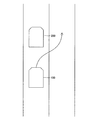
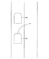
図4A乃至図4Cに、ドライバの意図に反して偶然PCB制御の実行条件が成立する可能性が高い例を示す。図4A、図4Bでは、車両100は、先行車両200の追従走行中に先行車両200が減速したことにより、AC制御により減速制御している。図4Aでは、ドライバが先行車両200を追い越すために操舵ハンドルを操作して図4Aの矢印に示す経路に沿って車線変更すると、先行車両200に一時的に接近するため、PCB制御の実行条件が成立する可能性が高い。図4Bでは、ドライバが操舵ハンドルを操作して図4Bの矢印に示す経路に沿って衝突を回避しようとすると、先行車両200に一時的に接近するため、PCB制御の実行条件が成立する可能性が高い。一方、図4Cでは、車両100は、先行車両200の追従走行中にカーブ路に差し掛かり、先行車両200が減速したことにより、AC制御により減速制御している。このとき、カーブ路の脇に停止している自転車300が、車両100の進行方向(矢印参照)を含む所定の範囲S(PCB制御の対象となる物標が検出される範囲)に含まれており、道路形状により自転車300に接近すると、PCB制御の実行条件が成立する可能性が高い。
4A to 4C show an example in which there is a high possibility that the execution condition of the PCB control is accidentally satisfied against the intention of the driver. In FIGS. 4A and 4B, the
上記の説明から明らかなように、「ドライバの意図に反して偶然PCB制御の実行条件が成立する場合」は衝突危険度が比較的に低いと予想される。このため、第1実施装置は、当該PCB制御がLPB制御(即ち、衝突危険度が比較的に低い場合に実行される制御)の場合、当該LPB制御の実行条件が成立したと判定されたときにAC制御による減速制御が実行されていれば、LPB制御は実行せずにAC制御を継続する。そして、当該LPB制御の実行条件が成立したと判定されたときにAC制御による減速制御が実行されていなければ(即ち、AC制御による加速制御又はアクセルオーバーライド制御が実行されていれば)、LPB制御を実行してAC制御を停止する。即ち、図4A乃至図4Cの例においてLPB制御の実行条件が成立すると判定されたとすると、当該判定がなされたときにAC制御による減速制御が実行されているため、LPB制御は実行されずAC制御が継続されることになる。このため、ドライバの期待に反してLPB制御が実行されてAC制御の実行が停止されることを防止できる。なお、「PCB制御の実行条件が成立したと判定されたときにAC制御による減速制御が実行されていること」を条件に含めているのは、AC制御が加速制御(加速度0を含む。)又はアクセルオーバーライド制御の場合、AC制御が減速制御の場合と異なり、AC制御による減速量を確保できず、これにより、たとえ衝突危険度が低い状況であっても、LPB制御だけでは減速量を十分に確保できない可能性があり、ドライバにブレーキ制御への介入を促すことが望ましいからである。 As is clear from the above explanation, it is expected that the collision risk is relatively low in the case of "when the execution condition of PCB control is accidentally satisfied against the intention of the driver". Therefore, when the PCB control is LPB control (that is, control executed when the collision risk is relatively low), the first executing device determines that the execution condition of the LPB control is satisfied. If the deceleration control by the AC control is executed, the AC control is continued without executing the LPB control. Then, if the deceleration control by AC control is not executed when it is determined that the execution condition of the LPB control is satisfied (that is, if the acceleration control or accelerator override control by AC control is executed), the LPB control is performed. To stop AC control. That is, if it is determined in the examples of FIGS. 4A to 4C that the execution condition of the LPB control is satisfied, the deceleration control by the AC control is executed when the determination is made, so that the LPB control is not executed and the AC control is performed. Will be continued. Therefore, it is possible to prevent the LPB control from being executed and the execution of the AC control being stopped contrary to the expectation of the driver. It should be noted that the condition that "the deceleration control by the AC control is executed when it is determined that the execution condition of the PCB control is satisfied" is included in the condition that the AC control is the acceleration control (including 0 acceleration). Or, in the case of accelerator override control, unlike the case of deceleration control, the deceleration amount by AC control cannot be secured, and thus the deceleration amount is sufficient by LPB control alone even in a situation where the collision risk is low. This is because it may not be possible to secure the vehicle, and it is desirable to encourage the driver to intervene in brake control.
上記概要に基づき、以下では、PCB制御、AC制御及びAC制御判定処理について詳細に説明する。なお、以下では、車両100の図示しないエンジンスイッチ(イグニッション・キー・スイッチ)がオンされてからオフされるまでの期間を「エンジンオン期間」とも称する。 Based on the above outline, the PCB control, AC control, and AC control determination process will be described in detail below. In the following, the period from when the engine switch (ignition key switch) of the vehicle 100 (not shown) is turned on to when it is turned off is also referred to as an "engine on period".
<第1実施装置の作動の詳細>
A.PCB制御
[自車両情報の取得]
まず、PCB制御について説明する。ECU10は、エンジンオン期間中、演算周期の経過毎に、センサ11乃至14並びにスイッチ17及び18から受信した信号に基づいて、車速、アクセルペダル操作量、ブレーキペダル操作量、ヨーレート、AC制御スイッチ17の状態及び車速・車間距離設定スイッチ18の状態(即ち、車両100の運転状態)を示す情報を自車両情報として取得する。加えて、ECU10は、車速及びヨーレートに基づいて車両100の進行方向を算出する。
<Details of operation of the first implementation device>
A. PCB control [acquisition of own vehicle information]
First, PCB control will be described. The
[物標情報の取得]
ECU10は、エンジンオン期間中、演算周期の経過毎に、レーダーセンサ15から受信した信号とカメラ16から受信した信号に基づく画像データから、車両100の周囲に移動可能な物体(以下、単に「物体」と称する。)が存在するか否かを判定する。ECU10は、物体が存在すると判定した場合、車両100から物体までの距離及び車両100に対する物体の方位を算出する。加えて、物体の速度と車両100の車速に基づいて車両100に対する物体の相対速度を算出する。
[Acquisition of target information]
The
ECU10は、レーダーセンサ15から受信した物体の信号とカメラ16から取得した物体の画像データとを融合(フュージョン)して融合物体を生成する。具体的には、レーダーセンサ15から受信した信号に基づいて算出した物体の距離及び相対速度により融合物体の縦位置を特定し、カメラ16から取得した画像データに基づいて算出した物体の横幅及び横位置により融合物体の横位置を特定する。加えて、ECU10は、車両、歩行者及び自転車等の物体をパターン化したデータをメモリ(ROM)に予め格納しており、当該データを用いてカメラ16から取得した画像データのパターンマッチングを行うことにより、当該画像データが示す物体が車両、歩行者及び自転車の何れに該当するかを識別する。
The
以下では、融合物体のうち、車両100の進行方向を含む所定の範囲(角度範囲)に位置している車両、歩行者及び自転車であって、それらの車幅方向(車両100の進行方向に直交する方向)の相対速度が0を含む所定の相対速度範囲内である融合物体を「物標」と規定する。即ち、例えば、パターンマッチングにより自転車と識別された融合物体が上記所定の範囲内に位置していたとしても、当該融合物体の車幅方向の相対速度が上記所定の相対速度範囲外である場合は物標には該当しない。加えて、物標には静止している融合物体も含まれる。ECU10は、車両100から物標までの距離、車両100に対する物標の方位、車両100に対する物標の相対速度及び物標が車両、歩行者及び自転車の何れであるかを示す情報を物標情報として取得する。なお、本実施形態ではレーダーセンサ15の走査範囲及びカメラ16の撮像範囲は、上記所定の範囲よりも広く設定されているが、この構成に限られない。走査範囲及び撮像範囲は、上記所定の範囲と略同一であってもよい。
In the following, among the fused objects, vehicles, pedestrians, and bicycles located in a predetermined range (angle range) including the traveling direction of the
[衝突予測時間の算出]
ECU10は、エンジンオン期間中、演算周期の経過毎に、物標として検出された融合物体のそれぞれについて衝突予測時間(TTC: Time To Collision。以下、「TTC」とも称する。)を算出する。各物標についてのTTCは、各物標までの距離を各物標に対する車両100の相対速度で除算することにより算出され得る。物標が複数存在する場合、ECU10は、各物標についてのTTCを比較し、その中から最も小さいTTCを有する物標を選択し、その選択された物標について後述するPCB制御を実行するか否かを判定する。
[Calculation of collision prediction time]
The
ECU10は、エンジンオン期間中、演算周期の経過毎に、選択された物標についてPCB制御を実行するための実行条件が成立するか否かを判定し、成立すると判定した場合、PCB制御を実行せずにAC制御を継続するか、PCB制御を実行してAC制御を停止するかを判定する。上述したようにPCB制御にはPB制御とLPB制御の2種類があるが、それぞれの実行条件は物標が他車両(典型的には、先行車両)であるか歩行者又は自転車であるかによって異なる。このため、以下では、PB制御とLPB制御について、物標が他車両である場合と歩行者又は自転車である場合とに分けて説明する。
The
[物標が他車両の場合におけるPB制御]
まず、物標が他車両の場合におけるPB制御について説明する。ドライバ自身の運転操作により他車両との衝突を回避する方法としては、ドライバのブレーキ操作による衝突回避(以下、「ブレーキ回避」とも称する。)と、ドライバの操舵ハンドル操作による衝突回避(以下、「操舵回避」とも称する。)がある。PB制御は、ドライバのブレーキ操作又は操舵操作だけでは衝突を回避できない可能性が高い場合(即ち、衝突危険度が比較的に高い場合)に実行されることが望ましい。
[PB control when the target is another vehicle]
First, PB control when the target is another vehicle will be described. As a method of avoiding a collision with another vehicle by the driver's own driving operation, collision avoidance by the driver's brake operation (hereinafter, also referred to as "brake avoidance") and collision avoidance by the driver's steering handle operation (hereinafter, "" Also called "steering avoidance"). It is desirable that the PB control be executed when there is a high possibility that the collision cannot be avoided only by the driver's braking operation or steering operation (that is, when the collision risk is relatively high).
図3は、ブレーキ回避限界時間TB及び操舵回避限界時間TSと、ラップ率LRとの関係を示すグラフであり、このグラフはメモリ(ROM)に格納されている。ここで、ブレーキ回避限界時間TBとは、ドライバによるブレーキ操作により他車両との衝突を回避できる限界の時間である。操舵回避限界時間TSとは、ドライバによる操舵ハンドル操作により他車両との衝突を回避できる限界の時間である。ラップ率LRは、図2に示すように、車両100と他車両200との車幅方向における重なり度合いを示す指標である。ラップ率LRは、車両100が他車両200と車両100の車幅方向において重なっている長さLを車両100の車幅Wで除算することにより算出され得る。
3, the brake avoidance limit time T B and steering avoidance limit time T S, is a graph showing the relationship between the overlapping ratio LR, this graph is stored in the memory (ROM). Here, the brake avoidance limit time T B, the time limit that can avoid a collision with another vehicle by a brake operation of the driver. The steering avoidance limit time T S, which is the time limit that can avoid a collision with another vehicle by the steering wheel operation of the driver. As shown in FIG. 2, the lap ratio LR is an index showing the degree of overlap between the
図3の縦軸はTTCを表し、横軸はラップ率LRを表す。縦軸の値は、紙面下方向に向かうほど小さくなる。横軸の値は、中央から外側に向かうほど小さくなる。横軸の右側部分は、車両100が他車両に対して右側に位置しているときのラップ率LRを表し、横軸の左側部分は、車両100が他車両に対して左側に位置しているときのラップ率LRを表す。
The vertical axis of FIG. 3 represents TTC, and the horizontal axis represents the lap ratio LR. The value on the vertical axis becomes smaller toward the bottom of the page. The value on the horizontal axis decreases from the center to the outside. The right part of the horizontal axis represents the lap ratio LR when the
図3に示すように、ブレーキ回避限界時間TBはラップ率によらず一定であるが、操舵回避限界時間TSはラップ率に応じて変化し、ラップ率LRが1のときに最も大きく、ラップ率LRが低くなるにつれて小さくなる。ラップ率LRがLR≧LR2(以下、「高ラップ」とも称する。)の場合、ブレーキ回避限界時間TB≦操舵回避限界時間TSであるため、ブレーキ操作によれば操舵ハンドル操作以下の時間で衝突回避できる。一方、ラップ率LRがLR1≦LR<LR2(以下、「低ラップ」とも称する。)の場合、操舵回避限界時間TS<ブレーキ回避限界時間TBであるため、操舵ハンドル操作によればブレーキ操作よりも短い時間で衝突回避できる。 As shown in FIG. 3, the brake avoidance limit time T B is constant regardless of the overlapping ratio, steering avoidance limit time T S varies depending on the overlapping ratio, the overlap ratio LR is highest at the 1, It becomes smaller as the lap ratio LR becomes lower. Overlap ratio LR is LR ≧ LR2 (hereinafter, "high wrap" as also referred.) For, since the brake avoidance limit time T B ≦ steering avoidance limit time T S, in the steering wheel operation following times according to the brake operation Collision can be avoided. On the other hand, the overlap ratio LR is LR1 ≦ LR <LR2 (hereinafter, also referred to as "low wrap".) When, for a steering avoidable-collision threshold time T S <brake avoidance limit time T B, the braking operation according to the steering wheel operation Collision avoidance can be done in a shorter time.
他方、このことは、別言すれば、高ラップの場合においてTTCがブレーキ回避限界時間TB未満のときはドライバのブレーキ操作だけでは他車両との衝突を回避できない可能性が高いこと、及び、低ラップの場合においてTTCが操舵回避限界時間TS未満のときはドライバの操舵ハンドル操作だけでは他車両との衝突を回避できない可能性が高いことを意味する。即ち、衝突危険度が比較的に高いことを意味する。 On the other hand, this other words, it is likely the TTC can not be avoided only braking driver when less than the brake avoidance limit time T B collision with another vehicle in the case of high lap, and, TTC means that there is a high possibility that only the steering wheel operation of the driver can not avoid a collision with another vehicle when less than steering avoidable-collision threshold time T S in the case of low wrap. That is, it means that the collision risk is relatively high.
このため、ECU10は、高ラップの場合においてTTCがブレーキ回避限界時間TB未満のとき、及び、低ラップの場合においてTTCが操舵回避限界時間TS未満のとき(即ち、ラップ率LR及びTTCが図3の太線及び横軸で囲まれる領域内に位置しているとき)は、通常の制動力を付与するPB制御の実行条件が成立したと判定し、PB制御を実行する。なお、ブレーキ回避限界時間TBは「第1の閾値」の一例に相当する。以下では、ブレーキ回避限界時間TBを「第1時間閾値TTCth1」とも称する。
Therefore,
[物標が他車両の場合におけるLPB制御]
次に、物標が他車両の場合におけるLPB制御について説明する。低ラップの場合においてTTCが操舵回避限界時間TS以上ブレーキ回避限界時間TB未満のときは、ブレーキ回避は困難であるため衝突可能性はあるものの、操舵回避は可能であるため衝突危険度は比較的に低い。このため、ECU10は、低ラップの場合においてTTCが操舵回避限界時間TS以上、且つ、ブレーキ回避限界時間TB未満のとき(即ち、ラップ率LR及びTTCが図3の二点鎖線と太線と「LR1を通り縦軸に平行な直線」とによって囲まれる領域内に位置しているとき)は、軽度の制動力を付与するLPB制御の実行条件が成立したと判定して、LPB制御を実行する。即ち、ECU10は、低ラップのときは二段階のPCB制御を実行する。
[LPB control when the target is another vehicle]
Next, LPB control when the target is another vehicle will be described. When TTC is less than the steering avoidance limit time T S or more brake avoidance limit time T B in the case of low wrap, although the collision probability for the brake avoidance is difficult there, the collision risk for steering avoidance is possible Relatively low. Therefore,
但し、LPB制御が軽度の制動力しか付与しない制御であるとしても、ドライバが操舵ハンドル操作により衝突回避するつもりであった場合にLPB制御が実行されると、LPB制御がドライバの運転操作と干渉し、ドライバに違和感、不快感を与える可能性がある。加えて、車両100が他車両を追い越すために車線変更する場合、車両100が他車両に対して車幅方向にずれるとともに他車両に一時的に接近し、その結果、低ラップとなるとともにTTCが操舵回避限界時間TS以上ブレーキ回避限界時間TB未満になることがある。この場合も、LPB制御が実行されると、ドライバは他車両との衝突回避が必要な状況とは認識していないため、制動力の付与は不要な制御となり、ドライバに違和感、不快感を与える可能性がある。
However, even if the LPB control is a control that applies only a light braking force, if the LPB control is executed when the driver intends to avoid a collision by operating the steering wheel, the LPB control interferes with the driving operation of the driver. However, it may cause discomfort and discomfort to the driver. In addition, when the
上述した状況は、以下の2つの条件が成立する場合に発生する可能性が高い。
(条件1)LPB実行条件がAC制御の実行中に成立したと判定される。
(条件2)LPB実行条件が成立したと判定されたときにAC制御による減速制御が実行されている。
そこで、ECU10は、LPB実行条件が成立したと判定した場合に常にLPB制御を実行するのではなく、上記2つの条件1、2が成立する場合においてはLPB制御を実行しない。これにより、LPB制御がドライバに不要な制御と認識される可能性を低減しつつ、上記2つの条件が成立する場合であったとしても実際には回避操作必要状況であったときは、AC制御の減速制御による減速量を確保することができる。加えて、上記2つの条件の少なくとも一方が成立しない場合はLPB制御による減速量を確保することができる。
The above situation is likely to occur when the following two conditions are met.
(Condition 1) It is determined that the LPB execution condition is satisfied during the execution of AC control.
(Condition 2) Deceleration control by AC control is executed when it is determined that the LPB execution condition is satisfied.
Therefore, the
なお、低ラップ時における操舵回避限界時間TSは「第2の閾値」の一例に相当する。以下では、LR1及びLR2を「第1ラップ率閾値LRth1」及び「第2ラップ率閾値LRth2」とも称し、操舵回避限界時間TSを「第3時間閾値TTCth3」とも称する。 Incidentally, steering avoidance limit time T S in the low wrap corresponds to an example of the "second threshold". Hereinafter, also referred to as the LR1 and LR2 "first overlap ratio threshold LRth1" and "second overlap ratio threshold LRth2", the steering avoidance limit time T S is also referred to as "third time threshold TTCth3".
[物標が歩行者又は自転車の場合におけるPB制御及びLPB制御]
続いて、物標が歩行者又は自転車の場合におけるPB制御及びLPB制御について説明する。ECU10は、物標が歩行者又は自転車の場合、二段階のPCB制御を実行する。即ち、ECU10は、TTCが歩行者・自転車用のPB制御の時間閾値未満のときは、PB制御の実行条件が成立したと判定してPB制御を実行し、TTCが歩行者・自転車用のPB制御の時間閾値以上、且つ、歩行者・自転車用のLPB制御の時間閾値未満のときは、LPB制御の実行条件が成立したと判定してLPB制御を実行する。但し、ECU10は、物標が他車両の場合と同様に、LPB実行条件が成立したと判定した場合に常にLPB制御を実行するのではなく、上記2つの条件1、2が成立する場合においてはLPB制御を実行しない。
歩行者・自転車用のLPB制御の時間閾値及び歩行者・自転車用のPB制御の時間閾値は何れも一定の値を有しており、前者の値は第1時間閾値TTCth1よりも僅かに大きな値に設定される。なお、歩行者・自転車用のLPB制御の時間閾値及び歩行者・自転車用のPB制御の時間閾値はそれぞれ「第1の閾値」及び「第2の閾値」の一例に相当する。以下では、歩行者・自転車用のLPB制御の時間閾値及び歩行者・自転車用のPB制御の時間閾値をそれぞれ「第2時間閾値TTCth2」及び「第4時間閾値TTCth4」と称する。
[PB control and LPB control when the target is a pedestrian or a bicycle]
Next, PB control and LPB control when the target is a pedestrian or a bicycle will be described. When the target is a pedestrian or a bicycle, the
Both the LPB control time threshold value for pedestrians / bicycles and the PB control time threshold value for pedestrians / bicycles have constant values, and the former value is slightly larger than the first time threshold value TTCth1. Is set to. The LPB control time threshold value for pedestrians / bicycles and the PB control time threshold value for pedestrians / bicycles correspond to an example of "first threshold value" and "second threshold value", respectively. Hereinafter, the LPB control time threshold value for pedestrians / bicycles and the PB control time threshold value for pedestrians / bicycles are referred to as “second time threshold value TTCth2” and “fourth time threshold value TTCth4”, respectively.
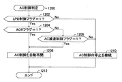
[PCB制御フラグの設定]
上記の説明から明らかなように、ECU10は、物標が他車両の場合においてTTCが第1時間閾値TTCth1未満の場合、及び、物標が歩行者又は自転車の場合においてTTCが第2時間閾値TTCth2未満の場合、PCB制御の実行条件が成立していると判定する。一方、ECU10は、物標が他車両の場合においてTTCが第1時間閾値TTCth1以上の場合、及び、物標が歩行者又は自転車の場合においてTTCが第2時間閾値TTCth2以上の場合、PCB制御の実行条件が成立していないと判定する。
[PCB control flag setting]
As is clear from the above description, the
PCB制御の実行条件が成立しているか否かを示す情報は、後述するAC制御判定を実施するか否かを判定するに際して利用される。このため、第1実施装置では、当該情報を示すフラグであるPCB制御フラグが設定される。ECU10は、PCB制御の実行条件が成立していると判定した場合、PCB制御フラグの値を1に設定し、PCB制御の実行条件が成立していないと判定した場合、PCB制御フラグの値を0に設定する。ECU10は、AC制御判定を実施するか否かを判定するに際してPCB制御フラグの値を利用する。
The information indicating whether or not the execution condition of the PCB control is satisfied is used when determining whether or not to execute the AC control determination described later. Therefore, in the first executing device, the PCB control flag, which is a flag indicating the information, is set. When the
[LPB制御フラグの設定]
PCB制御の実行条件が成立しているとき、ECU10は、物標が他車両の場合において「低ラップ時にTTCが第3時間閾値TTCth3以上のとき」、及び、物標が歩行者又は自転車の場合において「TTCが第4時間閾値TTCth4以上のとき」は、LPB制御の実行条件が成立したと判定する。一方、PCB制御の実行条件が成立していないとき、又は、後述するPB制御の実行条件が成立しているときは、ECU10はLPB制御の実行条件が成立していないと判定する。
[LPB control flag setting]
When the execution condition of the PCB control is satisfied, the
AC制御判定では、LPB制御の実行条件が成立しているか否かを示す情報を利用する。このため、第1実施装置では、当該情報を示すフラグであるLPB制御フラグが設定される。ECU10は、LPB制御の実行条件が成立していると判定した場合、LPB制御フラグの値を1に設定し、LPB制御の実行条件が成立していないと判定した場合、LPB制御フラグの値を0に設定する。ECU10は、AC制御判定においてLPB制御フラグの値を利用する。
In the AC control determination, information indicating whether or not the execution condition of LPB control is satisfied is used. Therefore, in the first executing device, the LPB control flag, which is a flag indicating the information, is set. When the
[PB制御フラグの設定]
PCB制御の実行条件が成立しているとき、ECU10は、物標が他車両の場合において「低ラップ時にTTCが第3時間閾値TTCth3未満、又は、高ラップ時のとき」、及び、物標が歩行者又は自転車の場合において「TTCが第4時間閾値TTCth4未満のとき」はPB制御の実行条件が成立したと判定してPB制御を実行する。一方、PCB制御の実行条件が成立していないとき、又は、上述したLPB制御の実行条件が成立しているときは、ECU10はPB制御の実行条件が成立していないと判定してPB制御を実行しない。
[PB control flag setting]
When the execution condition of the PCB control is satisfied, the
第1実施装置では、PCB制御がPB制御であるか否かを示すフラグであるPB制御フラグが設定される。ECU10は、PB制御の実行条件が成立していると判定した場合、PB制御フラグの値を1に設定し、PB制御の実行条件が成立していないと判定した場合、PB制御フラグの値を0に設定する。即ち、PCB制御フラグの値が1に設定されている場合においてLPB制御フラグの値が1に設定されるときはPB制御フラグの値は0に設定され、上記場合においてPB制御フラグの値が1に設定されるときはLPB制御フラグの値は0に設定される。
In the first executing device, a PB control flag, which is a flag indicating whether or not the PCB control is PB control, is set. When the
B.AC制御
[AC制御スイッチの状態]
次に、AC制御について説明する。ECU10は、エンジンオン期間中、演算周期の経過毎に、自車両情報として取得したAC制御スイッチ17の状態を表す情報がオン状態を示しているか否かを判定する。オン状態を示している場合、ECU10は、AC制御を実行する。
B. AC control
[AC control switch status]
Next, AC control will be described. During the engine on period, the
[先行車両情報の取得]
ECU10は、エンジンオン期間中、演算周期の経過毎に、物標として検出された融合物体の中に先行車両が存在するか否かを判定する。具体的には、ECU10は、レーダーセンサ15から受信した建造物の信号とカメラ16から取得した建造物の画像データとに基づいて道路形状を特定する。ECU10は、特定された道路形状に基づいて、車両100が走行している車線上において車両100の前方に他車両が存在するか否かを判定し、存在する場合、先行車両が存在すると判定し、存在しない場合、先行車両が存在しないと判定する。ECU10は、先行車両が存在すると判定した場合、AC制御の走行モードを追従走行モードに設定し、先行車両が存在しないと判定した場合、AC制御の走行モードを定速走行モードに設定する。本明細書が開示する発明は、走行モードが追従走行モードであること(先行車両が存在すること)が前提であるため、以下では、追従走行モードについて説明し、定速走行モードについては詳細な説明を省略する。ECU10は、先行車両までの距離及び相対速度を先行車両情報として取得する。
[Acquisition of preceding vehicle information]
The
[目標加速度の算出]
ECU10は、先行車両が存在する場合、エンジンオン期間中、演算周期の経過毎に、設定車間距離を維持しながら設定速度以下の速度で先行車両を追従走行するための目標加速度を算出する。設定車間距離及び設定速度は、車速・車間距離設定スイッチ18から自車両情報として取得した情報に基づいて決定される。目標加速度は、「先行車両までの距離(車間距離)と設定車間距離との偏差ΔD」及び「先行車両に対する車両100の相対速度VR」によって算出され得る。具体的には、目標加速度Gtgtは、以下の式に則って算出される。なお、K1及びK2は所定の正のゲイン(係数)である。
Gtgt=K1・ΔD+K2・VR
[Calculation of target acceleration]
When the preceding vehicle is present, the
Gtgt = K1 · ΔD + K2 · V R
ECU10は、車両100の加速度が算出された目標加速度に一致するようにスロットルアクチュエータ19の制御(AC制御による加速制御)又はブレーキアクチュエータ20の制御(AC制御による減速制御)を実行する。但し、目標加速度には上限加速度及び下限加速度(負の減速度)が予め設定されており、ECU10は、目標加速度が上限加速度を超える場合、車両100の加速度が上限加速度に一致するようにスロットルアクチュエータ19を制御し、目標加速度が下限加速度を下回る場合、車両100の加速度が下限加速度に一致するようにブレーキアクチュエータ20を制御する。
The
[AC減速制御フラグの設定]
上記の説明から明らかなように、ECU10は、目標加速度が0未満の場合はAC制御による減速制御を実行する。AC制御判定では、AC制御による減速制御が実行されているか否かを示す情報を利用する。このため、第1実施装置では、当該情報を示すフラグであるAC減速制御フラグが設定される。ECU10は、AC制御による減速制御が実行されている場合、AC減速制御フラグの値を1に設定し、AC制御による減速制御が実行されていない場合(即ち、AC制御による加速制御(加速度0を含む)又は後述するアクセルオーバーライド制御が実行されている場合)、AC減速制御フラグの値を0に設定する。ECU10は、AC制御判定においてAC減速制御フラグの値を利用する。
[AC deceleration control flag setting]
As is clear from the above description, the
[アクセルオーバーライド(AOR)フラグの設定]
AC制御による減速制御又はAC制御による加速制御中にドライバがアクセルペダルを踏み込むと、ECU10は、アクセルペダル操作量及び車速等に基づいてドライバのアクセル操作に基づく要求加速度を算出する。ECU10は、この要求加速度が上述した方法で算出された目標加速度を超えているか否かを判定し、超えている場合、車両100の加速度が要求加速度に一致するようにスロットルアクチュエータ19を制御する。これは、アクセルオーバーライド(AOR)制御と称される周知の制御である。即ち、ECU10は、要求加速度が目標加速度を超えている場合、AC制御による減速制御又はAC制御による加速制御に優先して、AOR制御を実行する。AC制御判定では、AOR制御が実行されているか否かを示す情報を利用する。このため、第1実施装置では、当該情報を示すフラグであるアクセルオーバーライド(AOR)フラグが設定される。ECU10は、AOR制御が実行されている場合、AORフラグの値を1に設定し、AOR制御が実行されていない場合、AORフラグの値を0に設定する。ECU10は、AC制御判定においてAORフラグの値を利用する。
[Accelerator Override (AOR) Flag Setting]
When the driver depresses the accelerator pedal during deceleration control by AC control or acceleration control by AC control , the
C.AC制御判定
次に、AC制御判定について説明する。AC制御判定は、AC制御の実行中にPCB制御(PB制御又はLPB制御の何れか)の実行条件が成立したと判定された場合、当該PCB制御を実行せずにAC制御を継続するか、当該PCB制御を実行してAC制御を停止するかを判定する処理である。このため、ECU10は、エンジンオン期間中、演算周期の経過毎に、PCB制御フラグが1であるか否かを判定し、PCB制御フラグ=1が成立すると判定した場合、AC制御判定を実施する。
C. AC control determination Next, the AC control determination will be described. In the AC control determination, if it is determined that the execution condition of the PCB control (either PB control or LPB control) is satisfied during the execution of the AC control, the AC control is continued without executing the PCB control. This is a process of determining whether to execute the PCB control and stop the AC control. Therefore, the
以下、具体的に説明する。一般に、AC制御による減速制御が実行されている(即ち、AOR制御が実行されていない)場合に回避操作必要状況に直面したとき、車両100は、PCB制御による減速量に加えて、AC制御(減速制御)による減速量を確保することができる。一方、AOR制御が実行されている場合は、車両100が加速制御されているため、回避操作必要状況に直面したときにAC制御による減速量を確保することはできない。この場合、たとえ衝突危険度が低い状況であっても、PCB制御だけでは減速量を十分に確保できない可能性があるため、PCB制御に引き続いてドライバによるブレーキ操作が実行されることが好ましい。そこで、ECU10は、AOR制御が実行されている場合(即ち、AORフラグ=1の場合)、衝突危険度の度合いに関わらず(即ち、PCB制御がPB制御であるかLPB制御であるかに関わらず)、PCB制御を実行してAC制御を停止する。これにより、確実にドライバにブレーキ制御への介入を促すことができる。
Hereinafter, a specific description will be given. In general, when faced with an avoidance operation requirement situation when deceleration control by AC control is executed (that is, AOR control is not executed), the
これに対し、AOR制御が実行されていない場合(即ち、AORフラグ=0の場合。別言すれば、AC制御による減速制御又はAC制御による加速制御が実行されている場合(以下、単に「AC制御が実行されている場合」とも称する。))において、衝突危険度が比較的に高いとき(即ち、PB制御フラグ=1、且つ、LPB制御フラグ=0のとき)は、ECU10は、PB制御を実行してAC制御を停止する。これは、PB制御の実行条件が成立したと判定したときに実行されているAC制御が加速制御であるか減速制御であるかに関わらず(即ち、AC減速制御フラグが1であるか0であるかに関わらず)行われる。これによっても、確実にドライバにブレーキ制御への介入を促すことができる。
On the other hand, when the AOR control is not executed (that is, when the AOR flag = 0. In other words, when the deceleration control by the AC control or the acceleration control by the AC control is executed (hereinafter, simply "AC". (Also referred to as "when control is being executed") ), when the collision risk is relatively high (that is, when the PB control flag = 1 and the LPB control flag = 0), the
一方、AOR制御が実行されていない場合(即ち、AORフラグ=0の場合。別言すれば、AC制御が実行されている場合)において、衝突危険度が比較的に低く、且つ、「LPB制御の実行条件が成立したと判定されたときにAC制御による減速制御が実行されている」場合(即ち、LPB制御フラグ=1、且つ、AC減速制御フラグ=1の場合)、ECU10は、LPB制御を実行せずにAC制御を継続する。これにより、ドライバの期待に反してLPB制御が実行されてAC制御が停止されることに起因してドライバに違和感や不快感を与える可能性を低減することができる。
On the other hand, when the AOR control is not executed (that is, when the AOR flag = 0, in other words, when the AC control is executed), the collision risk is relatively low and "LPB control". When it is determined that the execution condition of the above is satisfied, the deceleration control by AC control is executed "(that is, when the LPB control flag = 1 and the AC deceleration control flag = 1), the
他方、AOR制御が実行されていない場合(即ち、AORフラグ=0の場合。別言すれば、AC制御が実行されている場合)において、衝突危険度は比較的に低いものの、「LPB制御の実行条件が成立したと判定されたときにAC制御による加速制御が実行されている」場合(即ち、LPB制御フラグ=1、且つ、AC減速制御フラグ=0の場合)、AC制御による減速量を確保できず、これにより、たとえ衝突危険度が低い状況であっても、LPB制御だけでは減速量を十分に確保できない可能性がある。このため、上記の場合、ECU10はLPB制御を実行してAC制御を停止する。これにより、確実にドライバにブレーキ制御への介入を促すことができる。
On the other hand, when AOR control is not executed (that is, when AOR flag = 0, in other words, when AC control is executed), although the collision risk is relatively low, "LPB control" When it is determined that the execution condition is satisfied, the acceleration control by AC control is executed "(that is, when the LPB control flag = 1 and the AC deceleration control flag = 0), the deceleration amount by AC control is determined. Therefore, even in a situation where the collision risk is low, it may not be possible to secure a sufficient deceleration amount only by LPB control. Therefore, in the above case, the
<第1実施装置の制御フロー>
次に、第1実施装置の制御フローについて説明する。第1実施装置の車両制御ECU10のCPUは、エンジンオン期間中、図5乃至図9にフローチャートにより示したルーチンを演算時間の経過毎に実行するようになっている。
<Control flow of the first implementation device>
Next, the control flow of the first implementation device will be described. The CPU of the
CPUは、所定のタイミングになると、図5のステップ500から処理を開始して以下のステップ502処理を行う。
ステップ502:CPUは、PCB制御フラグの値を設定する処理を行う。図5のルーチンでは、CPUは、ステップ502において、図6にフローチャートにより示したルーチンを実行する。即ち、CPUは、ステップ502に進むと、図6のステップ600から処理を開始し、以下のステップ602の処理を行う。
At a predetermined timing, the CPU starts the process from
Step 502: The CPU performs a process of setting the value of the PCB control flag. In the routine of FIG. 5, the CPU executes the routine shown in the flowchart of FIG. 6 in
ステップ602:CPUは、上述したようにして車両100の自車両情報(車速、アクセルペダル操作量、ブレーキペダル操作量、ヨーレート、AC制御スイッチ17の状態及び車速・車間距離設定スイッチ18の状態)を取得し、ECU10のRAMに格納する。
Step 602: As described above, the CPU obtains the own vehicle information (vehicle speed, accelerator pedal operation amount, brake pedal operation amount, yaw rate, state of
次いで、CPUは、ステップ604に進んで、物標が1つ以上存在するか否かを判定する。物標が存在すると判定した場合、CPUは、ステップ604にて「Yes」と判定し、以下のステップ606乃至ステップ610の処理を順に行う。
The CPU then proceeds to step 604 to determine if one or more targets are present. When it is determined that the target exists, the CPU determines "Yes" in
ステップ606:CPUは、上述したようにして物標の物標情報(距離、方位及び相対速度)を取得し、ECU10のRAMに格納する。
ステップ608:CPUは、ステップ606で取得された物標情報を有する物標のそれぞれについて、物標までの距離を相対速度で除算することにより、物標までの衝突予測時間(TTC)を算出し、ECU10のRAMに格納する。
ステップ610:CPUは、ステップ608で算出されたTTCのうち、最小のTTCを有する物標を選択し(以下、当該物標を「選択物標」とも称する。)、ステップ606でECU10のRAMに格納された物標情報のうち選択物標の物標情報を「選択物標情報」としてラベリングする。
Step 606: The CPU acquires the target information (distance, direction, relative speed) of the target as described above, and stores it in the RAM of the
Step 608: The CPU calculates the collision prediction time (TTC) to the target by dividing the distance to the target by the relative velocity for each of the targets having the target information acquired in
Step 610: The CPU selects a target having the smallest TTC from the TTC calculated in step 608 (hereinafter, the target is also referred to as a “selected target”), and in
次いで、CPUは、ステップ612に進んで、ステップ606で取得された物標情報に基づき、ステップ610で選択された選択物標が歩行者又は自転車であるか否かを判定する。選択物標が歩行者又は自転車ではないと判定した場合(即ち、選択物標が他車両であると判定した場合)、CPUは、ステップ612にて「No」と判定し、以下のステップ613の処理を行う。
Next, the CPU proceeds to step 612 and determines whether or not the selected target selected in step 610 is a pedestrian or a bicycle based on the target information acquired in
ステップ613:CPUは、ステップ612で他車両であると判定された選択物標とのラップ率LRを算出し、ECU10のRAMに格納する。
Step 613: The CPU calculates the lap ratio LR with the selected object target determined to be another vehicle in
次いで、CPUは、ステップ614に進んで、ステップ613で算出されたラップ率LRが第1ラップ率閾値LRth1以上であるか否かを判定する。LR≧LRth1が成立すると判定した場合、CPUは、ステップ614にて「Yes」と判定し(即ち、少なくとも低ラップであると判定し)、以下のステップ616に進む。
Next, the CPU proceeds to step 614 and determines whether or not the lap rate LR calculated in
ステップ616では、CPUは、ステップ608で算出された他車両までのTTCが第1時間閾値TTCth1未満であるか否かを判定する。TTC<TTCth1が成立すると判定した場合、CPUは、ステップ616にて「Yes」と判定し(即ち、PCB制御の実行条件が成立していると判定し)、後述するステップ620に進む。
In
一方、ステップ612において選択物標が歩行者又は自転車であると判定した場合、CPUは、ステップ612にて「Yes」と判定し、以下のステップ618に進む。
On the other hand, when it is determined in
ステップ618では、CPUは、ステップ608で算出された歩行者又は自転車までのTTCが第2時間閾値TTCth2未満であるか否かを判定する。TTC<TTCth2が成立すると判定した場合、CPUは、ステップ618にて「Yes」と判定し(即ち、PCB制御の実行条件が成立していると判定し)、以下のステップ620に進む。
In
ステップ620:CPUは、PCB制御フラグの値を1に設定し、ECU10のRAMに格納する。その後、CPUは、ステップ624を経由して、図5のステップ504に進む。
Step 620: The CPU sets the value of the PCB control flag to 1 and stores it in the RAM of the
これに対し、ステップ604にて物標が存在しないと判定した場合、CPUは、ステップ604にて「No」と判定する(即ち、PCB制御の対象(PB制御及びLPB制御の対象)が存在しないと判定する。)。加えて、ステップ614にてLR≧LRth1が成立しないと判定した場合、CPUは、ステップ614にて「No」と判定する(即ち、高ラップ及び低ラップの何れにも該当しないと判定する。)。さらに、ステップ616にてTTC<TTCth1が成立しないと判定した場合、CPUは、ステップ616にて「No」と判定する(即ち、PCB制御の実行条件が成立していないと判定する。)。さらに、ステップ618にてTTC<TTCth2が成立しないと判定した場合、CPUは、ステップ618にて「No」と判定する(即ち、PCB制御の実行条件が成立していないと判定する。)。これらの場合、CPUは、以下のステップ622に進む。
On the other hand, when it is determined in
ステップ622:CPUは、PCB制御フラグの値、PB制御フラグの値及びLPB制御フラグの値を何れも0に設定し、ECU10のRAMに格納する。その後、CPUは、ステップ624を経由して、図5のステップ504に進む。
Step 622: The CPU sets the value of the PCB control flag, the value of the PB control flag, and the value of the LPB control flag to 0, and stores them in the RAM of the
CPUは、図5のステップ504に進むと、PB制御フラグ及びLPB制御フラグの値を設定する処理を行う。図5のルーチンでは、CPUは、ステップ504において、図7にフローチャートにより示したルーチンを実行する。即ち、CPUは、ステップ504に進むと、図7のステップ700から処理を開始し、以下のステップ702の処理を行う。
Proceeding to step 504 of FIG. 5, the CPU performs a process of setting the values of the PB control flag and the LPB control flag. In the routine of FIG. 5, the CPU executes the routine shown in the flowchart of FIG. 7 in
ステップ702:CPUは、PCB制御フラグの値が1であるか否かを判定する。PCB制御フラグ=1が成立すると判定した場合、CPUは、ステップ702にて「Yes」と判定し(即ち、PB制御又はLPB制御の何れかの実行条件が成立していると判定し)、以下のステップ704に進む。
Step 702: The CPU determines whether or not the value of the PCB control flag is 1. When it is determined that the PCB control flag = 1 is satisfied, the CPU determines "Yes" in step 702 (that is, it is determined that either the execution condition of PB control or LPB control is satisfied), and the
ステップ704では、CPUは、図6のステップ610で選択された選択物標について、図6のステップ612と同一の処理を行う。選択物標が歩行者又は自転車ではないと判定した場合(即ち、選択物標が他車両であると判定した場合)、CPUは、ステップ704にて「No」と判定し、以下のステップ706に進む。
In
ステップ706では、CPUは、図6のステップ613で算出されたラップ率LRが第2ラップ率閾値LRth2未満であるか否かを判定する。LR<LRth2が成立すると判定した場合、CPUは、ステップ706にて「Yes」と判定し(即ち、低ラップであると判定し)、以下のステップ708の処理を行う。
In
ステップ708:CPUは、メモリ(ROM)に格納されている図3に示したグラフを参照して、図6のステップ613で算出されたラップ率LRに対応する操舵回避限界時間TSを特定する。CPUは、特定された操舵回避限界時間TSを第3時間閾値TTCth3として設定し、ECU10のRAMに格納する。
Step 708: CPU refers to the graph shown in FIG. 3 which is stored in the memory (ROM), identifies the steering avoidance limit time T S corresponding to the calculated overlap ratio LR in
次いで、CPUは、ステップ710に進んで、図6のステップ608で算出された他車両までのTTCがステップ708で設定された第3時間閾値TTCth3以上であるか否かを判定する。TTC≧TTCth3が成立すると判定した場合、CPUは、ステップ710にて「Yes」と判定し(即ち、LPB制御の実行条件が成立したと判定し)、後述するステップ714に進む。
Next, the CPU proceeds to step 710 and determines whether or not the TTC to the other vehicle calculated in
一方、ステップ704において選択物標が歩行者又は自転車であると判定した場合、CPUは、ステップ704にて「Yes」と判定し、以下のステップ712に進む。
On the other hand, if it is determined in
ステップ712では、CPUは、図6のステップ608で算出された歩行者又は自転車までのTTCが第4時間閾値TTCth4以上であるか否かを判定する。TTC≧TTCth4が成立すると判定した場合、CPUは、ステップ712にて「Yes」と判定し(即ち、LPB制御の実行条件が成立したと判定し)、以下のステップ714に進む。
In
ステップ714:CPUは、LPB制御フラグの値を1に設定し、ECU10のRAMに格納する。その後、CPUは、ステップ718を経由して、図5のステップ506に進む。
Step 714: The CPU sets the value of the LPB control flag to 1 and stores it in the RAM of the
これに対し、ステップ706にてLR<LRth2が成立しないと判定した場合、CPUは、ステップ706にて「No」と判定する(即ち、高ラップであると判定する。)。加えて、ステップ710にてTTC≧TTCth3が成立しないと判定した場合、選択物標は車両であり、低ラップであり、TTC<TTCth3であるため、CPUは、ステップ710にて「No」と判定する(即ち、PB制御の実行条件が成立したと判定する。)。さらに、ステップ712にてTTC≧TTCth4が成立しないと判定した場合、選択物標は歩行者又は自転車であり、TTC<TTCth4であるため、CPUは、ステップ712にて「No」と判定する(即ち、PB制御の実行条件が成立したと判定する。)。これらの場合、CPUは、以下のステップ716の処理を行う。
On the other hand, when it is determined in
ステップ716:CPUは、PB制御フラグの値を1に設定し、ECU10のRAMに格納する。その後、CPUは、ステップ718を経由して、図5のステップ506に進む。
Step 716: The CPU sets the value of the PB control flag to 1 and stores it in the RAM of the
他方、ステップ702にてPCB制御フラグ=1が成立しない(即ち、PCB制御フラグ=0が成立する)と判定した場合、CPUは、ステップ702にて「No」と判定し、ステップ718を経由して、図5のステップ506に進む。この場合、PB制御フラグ及びLPB制御フラグの値は何れも0に設定されている(図6のステップ622参照)。
On the other hand, if it is determined in
CPUは、図5のステップ506に進むと、図6のステップ602で取得された自車両情報に基づいて、AC制御スイッチ17がオン状態であるか否かを判定する。オン状態であると判定した場合、CPUは、ステップ506にて「Yes」と判定し(即ち、AC制御が実行中であると判定し)、以下のステップ508の処理を行う。
When the CPU proceeds to step 506 of FIG. 5, it determines whether or not the
ステップ508:CPUは、AORフラグの値及びAC減速制御フラグの値を設定する処理を行う。図5のルーチンでは、CPUは、ステップ508において、図8にフローチャートにより示したルーチンを実行する。即ち、CPUは、ステップ508に進むと、図8のステップ800から処理を開始し、以下のステップ802に進む。
Step 508: The CPU performs a process of setting the value of the AOR flag and the value of the AC deceleration control flag. In the routine of FIG. 5, the CPU executes the routine shown in the flowchart of FIG. 8 in
ステップ802では、CPUは、上述したようにしてAOR制御が実行されているか否かを判定する。AOR制御が実行されていると判定した場合、CPUは、ステップ802にて「Yes」と判定し、以下のステップ804の処理を行う。
In
ステップ804:CPUは、AORフラグの値を1に設定し、ECU10のRAMに格納する。その後、CPUは、ステップ818を経由して図5のステップ510に進む。即ち、AOR制御はAC制御による減速制御又はAC制御による加速制御に優先して実行されるため、CPUは、AOR制御が実行されていると判定した場合、AC減速制御フラグの値を設定する処理は行わない(直前の周期の値が流用される)。
Step 804: The CPU sets the value of the AOR flag to 1 and stores it in the RAM of the
一方、ステップ802にてAOR制御が実行されていないと判定した場合、CPUは、ステップ802にて「No」と判定し、以下のステップ806の処理を行う。
On the other hand, when it is determined in
ステップ806:CPUは、AORフラグの値を0に設定し、ECU10のRAMに格納する。その後、CPUは、ステップ808及びステップ810の処理を順に行う。
Step 806: The CPU sets the value of the AOR flag to 0 and stores it in the RAM of the
ステップ808:CPUは、上述したようにして先行車両情報(距離及び相対速度)を取得し、ECU10のRAMに格納する。
ステップ810:CPUは、上述したようにして、設定車間距離を維持しながら設定速度以下の速度で先行車両を追従走行するための目標加速度を算出し、ECU10のRAMに格納する。
Step 808: The CPU acquires the preceding vehicle information (distance and relative speed) as described above and stores it in the RAM of the
Step 810: As described above, the CPU calculates the target acceleration for following the preceding vehicle at a speed equal to or lower than the set speed while maintaining the set inter-vehicle distance, and stores the target acceleration in the RAM of the
次いで、CPUは、ステップ812に進んで、ステップ810で算出された目標加速度が0未満(即ち、負の値)であるか否かを判定する。目標加速度<0が成立する場合、CPUは、ステップ812にて「Yes」と判定し(即ち、AC制御による減速制御が実行されていると判定し)、以下のステップ814の処理を行う。
Next, the CPU proceeds to step 812 and determines whether or not the target acceleration calculated in
ステップ814:CPUは、AC減速制御フラグの値を1に設定し、ECU10のRAMに格納する。その後、CPUは、ステップ818を経由して、図5のステップ510に進む。
Step 814: The CPU sets the value of the AC deceleration control flag to 1 and stores it in the RAM of the
一方、ステップ812において目標加速度<0が成立しない(即ち、目標加速度≧0が成立する)と判定した場合、CPUは、ステップ812にて「No」と判定し(即ち、AC制御による加速制御が実行されていると判定し)、以下のステップ816の処理を行う。
On the other hand, when it is determined in
ステップ816:CPUは、AC減速制御フラグの値を0に設定し、ECU10のRAMに格納する。その後、CPUは、ステップ818を経由して、図5のステップ510に進む。
Step 816: The CPU sets the value of the AC deceleration control flag to 0 and stores it in the RAM of the
CPUは、図5のステップ510に進むと、ステップ502の処理において設定されたPCB制御フラグの値が1であるか否かを判定する。PCB制御フラグ=1が成立する場合、CPUは、ステップ510にて「Yes」と判定し(即ち、PCB制御の実行条件が成立したと判定し)、以下のステップ512の処理を行う。
Proceeding to step 510 of FIG. 5, the CPU determines whether or not the value of the PCB control flag set in the process of
ステップ512:AC制御の実行中においてPCB制御フラグの値が1に設定されると、CPUは、PCB制御を実行せずにAC制御を継続するか、PCB制御を実行してAC制御を停止するかを判定するAC制御判定処理を行う。図5のルーチンでは、CPUは、ステップ512において、図9にフローチャートにより示したルーチンを実行する。即ち、CPUは、ステップ512に進むと、図9のステップ900から処理を開始し、以下のステップ901に進む。
Step 512: If the value of the PCB control flag is set to 1 during execution of AC control, the CPU either continues AC control without executing PCB control or executes PCB control to stop AC control. Performs AC control determination processing to determine whether or not. In the routine of FIG. 5, the CPU executes the routine shown in the flowchart of FIG. 9 in
ステップ901では、CPUは、図5のステップ508の処理において設定されたAORフラグの値が1であるか否かを判定する。AORフラグ=1が成立しないと判定した場合、CPUは、ステップ901にて「No」と判定し(即ち、AOR制御は実行されておらず、AC制御による減速制御又はAC制御による加速制御の実行中であると判定し)、以下のステップ902に進む。
In
ステップ902では、CPUは、図5のステップ504の処理において設定されたLPB制御フラグの値が1であるか否かを判定する。LPB制御フラグ=1が成立すると判定した場合、CPUは、ステップ902にて「Yes」と判定し(即ち、AC制御の実行中にLPB制御の実行条件が成立すると判定し)、以下のステップ904に進む。
In
ステップ904では、CPUは、図5のステップ508の処理において設定されたAC減速制御フラグの値が1であるか否かを判定する。AC減速制御フラグ=1が成立すると判定した場合、CPUは、ステップ904にて「Yes」と判定し(即ち、LPB制御の実行条件が成立したと判定されたときにAC制御による減速制御が実行されていると判定し)、以下のステップ906の処理を行う。
In
ステップ906:CPUは、LPB制御を実行せず、AC制御を継続する。その後、CPUは、ステップ910を経由して図5のステップ514に進み、本ルーチンを一旦終了する。
Step 906: The CPU does not execute the LPB control and continues the AC control. After that, the CPU proceeds to step 514 of FIG. 5 via
これに対し、ステップ901にてAORフラグ=1が成立すると判定した場合、CPUは、ステップ901にて「Yes」と判定する(即ち、PCB制御の実行条件が成立したと判定されたときにAOR制御が実行されていると判定する。)。加えて、ステップ902にてLPB制御フラグ=1が成立しない(即ち、LPB制御フラグ=0且つPB制御フラグ=1が成立する)と判定した場合、CPUは、ステップ902にて「No」と判定する(即ち、AC制御の実行中にPB制御が開始されると判定する。)。加えて、ステップ904にてAC減速制御フラグ=1が成立しないと判定した場合、CPUは、ステップ904にて「No」と判定する(即ち、LPB制御の実行条件が成立したと判定されたときにAC制御による加速制御が実行されていると判定する。)。これらの場合、CPUは、以下のステップ908の処理を行う。
On the other hand, when it is determined in
ステップ908:CPUは、AC制御を停止する。具体的には、ステップ901にて「Yes」と判定された場合、CPUは、PB制御フラグ=1が成立していればPB制御を実行してAC制御を停止し、LPB制御フラグ=1が成立していればLPB制御を実行してAC制御を停止する。ステップ902にて「No」と判定された場合、CPUは、PB制御を実行してAC制御を停止する。ステップ904にて「No」と判定された場合、CPUは、LPB制御を実行してAC制御を停止する。その後、CPUは、ステップ910を経由して図5のステップ514に進み、本ルーチンを一旦終了する。
Step 908: The CPU stops AC control. Specifically, when it is determined as " Yes " in
これに対し、図5のステップ506にてAC制御スイッチ17がオフ状態であると判定した場合、CPUは、ステップ506にて「No」と判定し(即ち、AC制御は実行されていないと判定し)、ステップ514に進み、本ルーチンを一旦終了する。加えて、ステップ510にてPCB制御フラグ=1が成立しないと判定した場合、CPUは、ステップ510にて「No」と判定し(即ち、AC制御は実行中であるが、PCB制御の実行条件は成立していないと判定し)、ステップ514に進み、本ルーチンを一旦終了する。
On the other hand, when it is determined in
第1実施装置の作用効果について説明する。第1実施装置では、AC制御の実行中にPCB制御の実行条件(制御対象が先行車両の場合はTTC<TTCth1であり、制御対象が歩行者又は自転車の場合はTTC<TTCth2。)が成立したと判定されたときにAC制御による減速制御が実行されている場合において、制御対象が先行車両の場合は以下の条件a及びbが成立するとき、又は、制御対象が歩行者又は自転車の場合は以下の条件cが成立するときは、PCB制御は実行されず、AC制御の実行が継続される。
・PCB制御の対象が先行車両の場合
(条件a)LRth1≦LR<LRth2
(条件b)TTCth3≦TTC
・PCB制御の対象が歩行者又は自転車の場合
(条件c)TTCth4≦TTC
The operation and effect of the first implementation device will be described. In the first executing device, the execution condition of the PCB control (TTC <TTCth1 when the control target is the preceding vehicle and TTC <TTCth2 when the control target is a pedestrian or a bicycle) is satisfied during the execution of the AC control. When the deceleration control by AC control is executed when it is determined that the control target is the preceding vehicle, the following conditions a and b are satisfied, or the control target is a pedestrian or a bicycle. When the following condition c is satisfied, the PCB control is not executed and the execution of the AC control is continued.
-When the target of PCB control is the preceding vehicle (Condition a) LRth1 ≤ LR <LRth2
(Condition b) TTC th3 ≤ TTC
-When the target of PCB control is a pedestrian or a bicycle (Condition c) TTCth4 ≤ TTC
PCB制御の実行条件が成立したと判定されたときにAC制御による減速制御が実行されている場合において、条件a及びbが成立するとき、又は、条件cが成立するときは、「ドライバが回避操作必要状況と認識していない状況」又は「ドライバが回避操作必要状況と認識しているものの、ブレーキ操作ではなく操舵ハンドルの操作により衝突を回避する意図を有している状況」において、TTC<TTCth1(対象が先行車両の場合)、又はTTC<TTCth2(対象が歩行者又は自転車の場合)が成立する場合である可能性が高い。即ち、ドライバがPCB制御が実行されることを想定しておらず、AC制御の実行が継続されることを予期している場合である可能性が高い。第1実施装置によれば、このような場合にはPCB制御は実行されず、AC制御の実行が継続される。このため、ドライバの期待に反してPCB制御が実行されてAC制御が停止されるという事態の発生を抑制でき、ドライバに違和感や不快感を与える可能性を低減することができる。 When it is determined that the execution condition of the PCB control is satisfied and the deceleration control by the AC control is executed, when the conditions a and b are satisfied, or when the condition c is satisfied, "the driver avoids". In "a situation that the driver does not recognize as an operation necessary situation" or "a situation that the driver recognizes as an avoidance operation necessary situation but intends to avoid the collision by operating the steering wheel instead of the brake operation", TTC < There is a high possibility that TTCth1 (when the target is a preceding vehicle) or TTC <TTCth2 (when the target is a pedestrian or a bicycle) is established. That is, there is a high possibility that the driver does not assume that the PCB control will be executed and expects that the execution of the AC control will continue. According to the first executing device, the PCB control is not executed in such a case, and the execution of the AC control is continued. Therefore, it is possible to suppress the occurrence of a situation in which the PCB control is executed and the AC control is stopped contrary to the expectation of the driver, and the possibility of giving the driver a sense of discomfort or discomfort can be reduced.
加えて、第1実施装置では、PCB制御がPB制御とLPB制御の2段階で構成されている。PCB制御の制御対象が先行車両であり、PCB制御の実行条件が成立している場合は、上記条件a及び条件bが成立するときはLPB制御による制動力を付与し(但し、PCB制御の実行条件が成立したと判定されたときにAC制御による減速制御が実行されていたときはLPB制御は実行しない)、条件a及び条件bの少なくとも一方が成立しないときはPB制御による制動力を付与する。そして、PCB制御の制御対象が歩行者又は自転車であり、PCB制御の実行条件が成立している場合は、上記条件cが成立するときはLPB制御による制動力を付与し(但し、PCB制御の実行条件が成立したと判定されたときにAC制御による減速制御が実行されていたときはLPB制御は実行しない)、条件cが成立しないときはPB制御による制動力を付与する。
この構成によれば、ドライバがPCB制御が実行されることを想定していない可能性が高い場合はLPB制御による軽度な制動力が付与される又はLPB制御自体が実行されないため、ドライバの運転操作と干渉する度合いを低減できる。加えて、実際には回避操作必要状況であった場合には、LPB制御が実行される場合は車両100に軽度な制動力が付与されるため、制動力を全く付与しない構成と比較して一定量の減速量を確保でき、LPB制御が実行されない場合はAC制御の減速制御による減速量を確保できる。このため、何れの場合も適切に衝突回避又は衝突被害の軽減を実現できる。
In addition, in the first implementation device, PCB control is composed of two stages, PB control and LPB control. When the control target of the PCB control is the preceding vehicle and the execution conditions of the PCB control are satisfied, the braking force by the LPB control is applied when the above conditions a and b are satisfied (however, the execution of the PCB control). LPB control is not executed when deceleration control by AC control is executed when it is determined that the condition is satisfied), and braking force by PB control is applied when at least one of condition a and condition b is not satisfied. .. When the control target of the PCB control is a pedestrian or a bicycle and the execution condition of the PCB control is satisfied, the braking force by the LPB control is applied when the above condition c is satisfied (however, the PCB control is applied. When it is determined that the execution condition is satisfied, the LPB control is not executed when the deceleration control by the AC control is executed), and when the condition c is not satisfied, the braking force by the PB control is applied.
According to this configuration, when it is highly likely that the driver does not assume that the PCB control is executed, a light braking force is applied by the LPB control or the LPB control itself is not executed, so that the driver's operation operation The degree of interference with can be reduced. In addition, when the avoidance operation is actually required, a light braking force is applied to the
加えて、第1実施装置では、ラップ率LRが低いほど第3時間閾値TTCth3が小さくなるように第3時間閾値TTCth3を変更するように構成されている。この構成によれば、ラップ率LRが低くなるほど、先行車両までのTTCが短くなっても(即ち、車両100が先行車両に接近しても)、PCB制御が実行され難く、且つ、AC制御が継続され易くなる。ラップ率LRが低くなるほど、車両100が先行車両を追い越すため、又は、車両100のドライバが操舵ハンドル操作により先行車両との衝突を回避するため、に先行車両との距離が短くなる可能性が高い。このため、上記の構成によれば、ドライバの期待に反してPCB制御が実行されてAC制御が停止される可能性を一層低減することができる。
In addition, the first implementing apparatus is configured to change the third time threshold TTCth3 so that the lower the lap ratio LR, the smaller the third time threshold TTCth3. According to this configuration, as the lap ratio LR becomes lower, even if the TTC to the preceding vehicle becomes shorter (that is, even if the
(第2実施形態)
次に、第2実施形態に係る車両制御装置(以下、第2実施装置と称する。)について説明する。第2実施装置は、図5のステップ512のAC制御判定処理のみが第1実施装置と異なっている。具体的には、第1実施装置では、PCB制御の実行条件が成立したと判定されたときにAOR制御が実行されていると判定された場合、PCB制御の種類によらず、PCB制御が実行されてAC制御が停止される(図9のステップ901の「Yes」を参照)。これに対し、第2実施装置では、PCB制御の実行条件が成立したと判定されたときにAOR制御が実行されていると判定された場合に、PCB制御の種類がLPB制御であるときは、当該LPB制御が実行されずAC制御が継続される(後述する図10のステップ1004の「Yes」を参照)。以下、第2実施装置のAC制御判定処理(図5のステップ512を参照)について説明する。
(Second Embodiment)
Next, the vehicle control device (hereinafter, referred to as the second embodiment) according to the second embodiment will be described. The second implementation device differs from the first implementation device only in the AC control determination process of
ステップ512:CPUは、AC制御判定処理を行う。第2実施装置における図5のルーチンでは、CPUは、ステップ512に進むと、図10のステップ1000から処理を開始し、以下のステップ1002に進む。
Step 512: The CPU performs AC control determination processing. In the routine of FIG. 5 in the second executing apparatus, when the CPU proceeds to step 512, the process starts from
ステップ1002では、CPUは、図5のステップ504の処理において設定されたLPB制御フラグの値が1であるか否かを判定する。LPB制御フラグ=1が成立すると判定した場合、CPUは、ステップ1002にて「Yes」と判定し(即ち、AC制御の実行中にLPB制御の実行条件が成立すると判定し)、以下のステップ1004に進む。
In
ステップ1004では、CPUは、図5のステップ508の処理において設定されたAORフラグの値が1であるか否かを判定する。AORフラグ=1が成立すると判定した場合、CPUは、ステップ1004にて「Yes」と判定し(即ち、LPB制御の実行条件が成立したと判定されたときにAOR制御が実行されていると判定し)、後述するステップ1108の処理を行う。
In
一方、ステップ1004にてAORフラグ=1が成立しない(即ち、AORフラグ=0が成立する)と判定した場合、CPUは、ステップ1004にて「No」と判定し(即ち、LPB制御の実行条件が成立したと判定されたときにAOR制御ではなくAC制御による減速制御又はAC制御による加速制御が実行されていると判定し)、以下のステップ1006に進む。
On the other hand, if it is determined in
ステップ1006では、CPUは、図5のステップ508の処理において設定されたAC減速制御フラグの値が1であるか否かを判定する。AC減速制御フラグ=1が成立すると判定した場合、CPUは、ステップ1006にて「Yes」と判定し(即ち、LPB制御の実行条件が成立したと判定されたときにAC制御による減速制御が実行されていると判定し)、以下のステップ1008の処理を行う。
In
ステップ1008:CPUは、LPB制御を実行せず、AC制御を継続すると判定する。その後、CPUは、ステップ1012を経由して図5のステップ514に進み、本ルーチンを一旦終了する。
Step 1008: The CPU determines that the LPB control is not executed and the AC control is continued. After that, the CPU proceeds to step 514 of FIG. 5 via
これに対し、ステップ1002にてLPB制御フラグ=1が成立しない(即ち、LPB制御フラグ=0且つPB制御フラグ=1が成立する)と判定した場合、CPUは、ステップ1002にて「No」と判定する(即ち、AC制御の実行中にPB制御が実行されると判定する。)。加えて、ステップ1006にてAC減速制御フラグ=1が成立しないと判定した場合、CPUは、ステップ1006にて「No」と判定する(即ち、LPB制御の実行条件が成立したと判定されたときにAC制御による加速制御が実行されていると判定する。)。これらの場合、CPUは、以下のステップ1010の処理を行う。
On the other hand, if it is determined in
ステップ1010:CPUは、PCB制御(PB制御又はLPB制御)を実行してAC制御を停止すると判定する。その後、CPUは、ステップ1012を経由して図5のステップ514に進み、本ルーチンを一旦終了する。
Step 1010: The CPU determines that the PCB control (PB control or LPB control) is executed and the AC control is stopped. After that, the CPU proceeds to step 514 of FIG. 5 via
この構成によっても、第1実施装置と同様の作用効果を奏することができる。
ここで、第1実施装置では、PCB制御の実行条件が成立したと判定されたときにAOR制御が実行されていると判定された場合、PCB制御が実行されてAC制御が停止される。この構成が採用された理由は、AOR制御は加速制御であるためAC制御による減速量を確保することができず、たとえ衝突危険度が低い状況であっても十分な減速量を確保できない可能性があるからである。
Even with this configuration, it is possible to obtain the same effects as those of the first implementation device.
Here, in the first executing device, when it is determined that the execution condition of the PCB control is satisfied and it is determined that the AOR control is being executed, the PCB control is executed and the AC control is stopped. The reason why this configuration is adopted is that since the AOR control is acceleration control, it is not possible to secure the deceleration amount by AC control, and it is possible that a sufficient deceleration amount cannot be secured even in a situation where the collision risk is low. Because there is.
しかしながら、見方を変えれば、AOR制御はドライバの意思に基づく加速制御であるため、回避操作必要状況に直面した場合、ドライバが主体的にブレーキ制御に介入する可能性が極めて高く、十分な減速量を確保できると考えることもできる。このため、第2実施装置では、PCB制御の実行条件が成立したと判定されたときにAOR制御が実行されていると判定された場合において、PCB制御の種類がLPB制御であるときは、LPB制御が実行されず、AC制御が継続される。 However, from a different point of view, since AOR control is acceleration control based on the driver's intention, it is extremely likely that the driver will voluntarily intervene in brake control when faced with a situation requiring avoidance operation, and a sufficient deceleration amount. It can also be considered that Therefore, in the second executing apparatus, when it is determined that the AOR control is executed when it is determined that the execution condition of the PCB control is satisfied, and the type of the PCB control is LPB control, the LPB The control is not executed and the AC control is continued.
この構成によれば、衝突危険度が比較的に低い回避操作必要状況に直面した場合、LPB制御が実行されなくても、ドライバが主体的にブレーキ制御に介入することによりドライバのブレーキ操作による減速量を確保できる。このため、ドライバにブレーキ制御への介入を促すためにAC制御を停止する必要がなくなる。従って、第2実施装置の構成によれば、衝突危険度が比較的に低い回避操作必要状況では十分な減速量を確保しつつ、ドライバの期待に反してLPB制御が実行されてAC制御が停止されることに起因してドライバに違和感や不快感を与える可能性を一層低減することができる。
加えて、第2実施装置では、PCB制御の実行条件が成立したと判定されたときにAOR制御が実行されていた場合において、制御対象が先行車両の場合は上記条件a及びbが成立するとき、又は、制御対象が歩行者又は自転車の場合は上記条件cが成立するときにも、PCB制御は実行されず、AC制御の実行が継続される。
PCB制御の実行条件が成立したと判定されたときにAOR制御が実行されている場合において、条件a及びbが成立するとき、又は、条件cが成立するときは、「ドライバが回避操作必要状況と認識していない状況」において、TTC<TTCth1(対象が先行車両の場合)、又はTTC<TTCth2(対象が歩行者又は自転車の場合)が成立する場合である可能性が高い。即ち、ドライバがPCB制御が実行されることを想定しておらず、AC制御の実行が継続されることを予期している場合である可能性が高い。第2実施装置によれば、このような場合にもPCB制御は実行されず、AC制御の実行が継続される。このため、ドライバに違和感や不快感を与える可能性をより低減することができる。
According to this configuration, when faced with a situation requiring avoidance operation with a relatively low collision risk, the driver proactively intervenes in the brake control to decelerate by the driver's brake operation even if the LPB control is not executed. The amount can be secured. Therefore, it is not necessary to stop the AC control in order to encourage the driver to intervene in the brake control. Therefore, according to the configuration of the second implementation device, LPB control is executed contrary to the driver's expectation and AC control is stopped while ensuring a sufficient deceleration amount in the situation where avoidance operation is required when the collision risk is relatively low. It is possible to further reduce the possibility of causing discomfort or discomfort to the driver due to the driver.
In addition, in the second executing device, when the AOR control is executed when it is determined that the execution condition of the PCB control is satisfied, and when the control target is the preceding vehicle, the above conditions a and b are satisfied. Or, when the control target is a pedestrian or a bicycle, the PCB control is not executed and the execution of the AC control is continued even when the above condition c is satisfied.
When it is determined that the execution condition of the PCB control is satisfied and the AOR control is executed, when the conditions a and b are satisfied, or when the condition c is satisfied, "the driver needs to avoid the operation". There is a high possibility that TTC <TTCth1 (when the target is a preceding vehicle) or TTC <TTCth2 (when the target is a pedestrian or a bicycle) is established in "a situation not recognized as". That is, there is a high possibility that the driver does not assume that the PCB control will be executed and expects that the execution of the AC control will continue. According to the second executing device, the PCB control is not executed even in such a case, and the execution of the AC control is continued. Therefore, the possibility of giving the driver a sense of discomfort or discomfort can be further reduced.
(第3実施形態)
次に、第3実施形態に係る車両制御装置(以下、第3実施装置と称する。)について説明する。第3実施装置は、図5のステップ512のAC制御判定処理のみが第1実施装置と異なっている。具体的には、第3実施装置は、AC制御の実行中にPCB制御実行条件が成立した場合、PB制御又はLPB制御の何れかが必ず実行される点と、AC制御の実行中にPCB制御が開始された場合にAC制御の実行が停止される点と、LPB制御の実行条件が成立した時点においてAC制御による減速制御が実行されていた場合、LPB制御の実行後にAC制御が自動的に再開される点において、第1実施装置と異なっている。以下、第1実施装置との相違点について主に説明する。
(Third Embodiment)
Next, the vehicle control device (hereinafter, referred to as the third embodiment) according to the third embodiment will be described. The third implementation device differs from the first implementation device only in the AC control determination process of
<第3実施装置の作動の概要>
第3実施装置は、追従走行モードのAC制御の実行中にPCB制御が開始された場合、AC制御の実行を停止する。そして、第3実施装置は、PCB制御の実行が終了したときにAC制御を自動的に再開するか否かを判定する。(AC制御判定)。PCB制御の実行後にAC制御を自動再開すると、ドライバが第3実施装置の性能を過信してPCB制御の実行後にブレーキ制御に介入しなくなる可能性がある。このため、衝突危険度が比較的に高いと予想される状況では、PCB制御の実行後もAC制御の停止を継続して、確実にドライバにブレーキ制御への介入を促すことが望ましい。従って、第3実施装置は、当該PCB制御がPB制御(即ち、衝突危険度が比較的に高い場合に実行される制御)の場合、PB制御だけでは不十分と判定して、PB制御の実行後にAC制御の停止を継続する。
<Outline of operation of the third implementation device>
When the PCB control is started during the execution of the AC control in the follow-up travel mode, the third executing device stops the execution of the AC control. Then, the third executing device determines whether or not to automatically restart the AC control when the execution of the PCB control is completed. (AC control judgment). If the AC control is automatically restarted after the PCB control is executed, the driver may overconfidence in the performance of the third executing device and may not intervene in the brake control after the PCB control is executed. Therefore, in a situation where the collision risk is expected to be relatively high, it is desirable to continue stopping the AC control even after the PCB control is executed to surely encourage the driver to intervene in the brake control. Therefore, when the PCB control is PB control (that is, control executed when the collision risk is relatively high), the third executing apparatus determines that PB control alone is insufficient and executes PB control. Later, the stop of AC control is continued.
一方、PCB制御の実行後、常にAC制御の停止を継続する構成では、ドライバの意図に反して偶然PCB制御の実行条件が成立してPCB制御が実行されてしまった場合に、ドライバの期待に反してAC制御が自動再開されなくなってしまうため、望ましくない。 On the other hand, in the configuration in which the AC control is always stopped after the PCB control is executed, the driver's expectation is met when the PCB control execution condition is accidentally satisfied and the PCB control is executed against the intention of the driver. On the contrary, AC control is not automatically restarted, which is not desirable.
図4A乃至図4Cを参照して上述したように、「ドライバの意図に反して偶然PCB制御が実行される場合」は衝突危険度が比較的に低いと予想される。このため、第3実施装置は、当該PCB制御がLPB制御(即ち、衝突危険度が比較的に低い場合に実行される制御)の場合、当該LPB制御の実行条件が成立した時点においてAC制御による減速制御が実行されていれば、当該LPB制御が終了したときにAC制御を自動的に再開する。そして、当該LPB制御の実行条件が成立した時点においてAC制御による減速制御が実行されていなければ(即ち、AC制御による加速制御又はアクセルオーバーライド制御が実行されていれば)、当該LPB制御が終了した後もAC制御の停止を継続する。即ち、図4A乃至図4Cの例においてLPB制御の実行条件が成立すると判定されたとすると、LPB制御の実行条件が成立した時点においてAC制御による減速制御が実行されているため、LPB制御が終了したときにAC制御が自動再開されることになる。このため、ドライバの期待に反してLPB制御の終了後にAC制御の停止が継続されてしまうことを防止できる。 As described above with reference to FIGS. 4A to 4C, it is expected that the collision risk is relatively low in the case where the PCB control is accidentally executed against the intention of the driver. Therefore, when the PCB control is LPB control (that is, control executed when the collision risk is relatively low), the third executing device uses AC control when the execution condition of the LPB control is satisfied. If the deceleration control is executed, the AC control is automatically restarted when the LPB control is completed. Then, if the deceleration control by AC control is not executed at the time when the execution condition of the LPB control is satisfied (that is, if the acceleration control or accelerator override control by AC control is executed), the LPB control is terminated. After that, the AC control will continue to be stopped. That is, if it is determined that the LPB control execution condition is satisfied in the examples of FIGS. 4A to 4C, the LPB control is terminated because the deceleration control by the AC control is executed when the LPB control execution condition is satisfied. Occasionally, AC control will be automatically restarted. Therefore, contrary to the expectation of the driver, it is possible to prevent the AC control from being continuously stopped after the LPB control is completed.
上記概要に基づき、以下では、PCB制御及びAC制御判定処理について第1実施装置と相違している点を中心に詳細に説明する。 Based on the above outline, the PCB control and the AC control determination process will be described in detail below, focusing on the differences from the first executing apparatus.
<第3実施装置の作動の詳細>
D.PCB制御
[物標が他車両の場合におけるLPB制御]
低ラップの場合においてTTCが第3時間閾値TTCth3以上第1時間閾値TTCth1未満のときは、ブレーキ回避は困難であるため衝突可能性はあるものの、操舵回避は可能であるため衝突危険度は比較的に低い。このようなときにPB制御と同等の制動力を付与すると、ドライバが操舵ハンドル操作により衝突回避するつもりであった場合にドライバの運転操作と干渉してしまうため、ドライバに違和感、不快感を与えることになる。加えて、車両100が他車両を追い越すために車線変更する場合、車両100が他車両に対して車幅方向にずれるとともに他車両に一時的に接近し、その結果、低ラップとなるとともにTTCが第3時間閾値TTCth3以上第1時間閾値TTCth1未満になることがある。この場合も、PB制御と同等の制動力を付与すると、ドライバは他車両との衝突回避が必要な状況とは認識していないため、当該制動力の付与は不要な制御となり、ドライバに違和感、不快感を与えることになる。その一方で、これを解消するために制動力を一切付与しないとすると、実際はPCB制御が必要であった場合に十分な減速量を確保できなくなる。
<Details of operation of the third implementation device>
D. PCB control
[LPB control when the target is another vehicle]
In the case of low lap, when the TTC is equal to or higher than the third time threshold TTCth3 and less than the first time threshold TTCth1, there is a possibility of collision because it is difficult to avoid braking, but the risk of collision is relatively high because steering avoidance is possible. Low to. In such a case, if a braking force equivalent to that of PB control is applied, the driver will interfere with the driving operation of the driver when the driver intends to avoid a collision by operating the steering wheel, which gives the driver a sense of discomfort and discomfort. It will be. In addition, when the
そこで、ECU10は、低ラップの場合においてTTCが第3時間閾値TTCth3以上、且つ、第1時間閾値TTCth1未満のときは、軽度の制動力を付与するLPB制御の実行条件が成立したと判定して、LPB制御を実行する。即ち、ECU10は、低ラップのときは二段階のPCB制御を実行する。なお、LPB制御の制動力は、「車両100のドライバがPCB制御が実行されるとは想定していない場合」にLPB制御が実行されたとしても許容できる(それほど不要な制御とは感じない)程度の大きさに設定されることが好ましい。
Therefore, when the TTC is equal to or higher than the third time threshold value TTCth3 and less than the first time threshold value TTCth1 in the case of low lap, the
[物標が歩行者又は自転車の場合におけるPB制御及びLPB制御]
ECU10は、TTCが第4時間閾値TTCth4未満のときは、PB制御の実行条件が成立したと判定してPB制御を実行し、TTCが第4時間閾値TTCth4以上、且つ、第2時間閾値TTCth2未満のときは、LPB制御の実行条件が成立したと判定してLPB制御を実行する。TTCが減少するにつれてLPB制御からPB制御に切り替える構成とすることにより、PCB制御がドライバに不要な制御と認識される可能性を低減しつつ、PCB制御が必要であった場合のための減速量を確保することができる。
[PB control and LPB control when the target is a pedestrian or a bicycle]
When the TTC is less than the 4th time threshold TTCth4, the
[PCB制御フラグの設定]
ECU10は、PCB制御の実行条件が成立していると判定した場合、PCB制御フラグの値を1に設定し、PCB制御(即ち、PB制御又はLPB制御の何れか)を実行する。一方、ECU10は、PCB制御の実行条件が成立していないと判定した場合、PCB制御フラグの値を0に設定し、PCB制御を実行しない。即ち、PCB制御フラグの値が1であることは、第1実施装置ではPCB制御の実行条件が成立していることを意味したのに対し、第3実施装置ではPCB制御の実行条件が成立してPCB制御を実行することを意味する。
[PCB control flag setting]
When the
[LPB制御フラグの設定]
ECU10は、LPB制御の実行条件が成立していると判定した場合、LPB制御フラグの値を1に設定し、LPB制御を実行する。一方、ECU10は、LPB制御の実行条件が成立していないと判定した場合、LPB制御を実行しない。即ち、LPB制御フラグの値が1であることは、第1実施装置ではLPB制御の実行条件が成立していることを意味したのに対し、第3実施装置ではLPB制御の実行条件が成立してLPB制御を実行することを意味する。
[LPB control flag setting]
When the
E.AC制御判定
AC制御判定は、AC制御の実行中にPCB制御(PB制御又はLPB制御の何れか)が開始された場合、当該PCB制御が終了したときにAC制御を自動的に再開するか否かを判定する処理である。このため、ECU10は、エンジンオン期間中、演算周期の経過毎に、PCB制御フラグが1であるか否かを判定し、PCB制御フラグ=1が成立すると判定した場合、AC制御判定を実施する。
E. AC control judgment In the AC control judgment, if PCB control (either PB control or LPB control) is started during execution of AC control, whether or not AC control is automatically restarted when the PCB control ends. It is a process of determining whether or not. Therefore, the
以下、具体的に説明する。ECU10は、AOR制御が実行されている場合(即ち、AORフラグ=1の場合)、衝突危険度の度合いに関わらず(即ち、PCB制御がPB制御であるかLPB制御であるかに関わらず)、AC制御の停止を継続する(より詳細には、PCB制御が開始されたときに停止されたAC制御を、PCB制御の終了後も継続して停止する。)。これにより、確実にドライバにブレーキ制御への介入を促すことができる。
Hereinafter, a specific description will be given. When the AOR control is executed (that is, when the AOR flag = 1), the
これに対し、AOR制御が実行されていない場合(即ち、AORフラグ=0の場合。別言すれば、AC制御が実行されている場合)において、衝突危険度が比較的に高いとき(即ち、PB制御フラグ=1、且つ、LPB制御フラグ=0のとき)は、ECU10は、AC制御の停止を継続する(より詳細には、PB制御が開始されたときに停止されたAC制御を、PB制御の終了後も継続して停止する。)。これは、PB制御の実行条件が成立した時点において実行されているAC制御が加速制御であるか減速制御であるかに関わらず(即ち、AC減速制御フラグが1であるか0であるかに関わらず)行われる。これによっても、確実にドライバにブレーキ制御への介入を促すことができる。
On the other hand, when the AOR control is not executed (that is, when the AOR flag = 0, in other words, when the AC control is executed), the collision risk is relatively high (that is, when the collision risk is executed). When the PB control flag = 1 and the LPB control flag = 0), the
一方、AOR制御が実行されていない場合(即ち、AORフラグ=0の場合。別言すれば、AC制御が実行されている場合)において、衝突危険度が比較的に低く、且つ、「LPB制御の実行条件が成立した時点においてAC制御による減速制御が実行されている」場合(即ち、LPB制御フラグ=1、且つ、AC減速制御フラグ=1の場合)、ECU10は、LPB制御が終了したときにAC制御を自動的に再開する。これにより、ドライバの期待に反してLPB制御の終了後にAC制御の停止が継続されることに起因してドライバに違和感や不快感を与える可能性を低減することができる。
On the other hand, when the AOR control is not executed (that is, when the AOR flag = 0, in other words, when the AC control is executed), the collision risk is relatively low and "LPB control". When the deceleration control by AC control is executed when the execution condition of is satisfied (that is, when the LPB control flag = 1 and the AC deceleration control flag = 1), the
他方、AOR制御が実行されていない場合(即ち、AORフラグ=0の場合。別言すれば、AC制御が実行されている場合)において、衝突危険度は比較的に低いものの、「LPB制御の実行条件が成立した時点においてAC制御による加速制御が実行されている」場合(即ち、LPB制御フラグ=1、且つ、AC減速制御フラグ=0の場合)、AC制御による減速量を確保できず、これにより、たとえ衝突危険度が低い状況であっても、LPB制御だけでは減速量を十分に確保できない可能性がある。このため、上記の場合、ECU10はAC制御の停止を継続する(より詳細には、LPB制御が開始されたときに停止されたAC制御を、LPB制御の終了後も継続して停止する。)。これにより、確実にドライバにブレーキ制御への介入を促すことができる。
On the other hand, when AOR control is not executed (that is, when AOR flag = 0, in other words, when AC control is executed), although the collision risk is relatively low, "LPB control" When the acceleration control by AC control is executed when the execution condition is satisfied (that is, when the LPB control flag = 1 and the AC deceleration control flag = 0), the deceleration amount by AC control cannot be secured. As a result, even in a situation where the collision risk is low, there is a possibility that a sufficient deceleration amount cannot be secured only by LPB control. Therefore, in the above case, the
次に、第3実施装置のAC制御判定処理(図5のステップ512を参照)について説明する。
ステップ512:CPUは、AC制御判定処理を行う。第3実施装置における図5のルーチンでは、CPUは、ステップ512に進むと、図11のステップ1100から処理を開始し、以下のステップ1101に進む。
Next, the AC control determination process of the third implementation device (see
Step 512: The CPU performs AC control determination processing. In the routine of FIG. 5 in the third executing apparatus, when the CPU proceeds to step 512, the process starts from step 1100 of FIG. 11 and proceeds to the following
ステップ1101では、CPUは、図5のステップ508の処理において設定されたAORフラグの値が1であるか否かを判定する。AORフラグ=1が成立しないと判定した場合、CPUは、ステップ1101にて「No」と判定し(即ち、AOR制御は実行されておらず、AC制御の実行中であると判定し)、以下のステップ1102に進む。
In
ステップ1102では、CPUは、図5のステップ504の処理において設定されたLPB制御フラグの値が1であるか否かを判定する。LPB制御フラグ=1が成立すると判定した場合、CPUは、ステップ1102にて「Yes」と判定し(即ち、AC制御の実行中にLPB制御が開始されると判定し)、以下のステップ1104に進む。
In
ステップ1104では、CPUは、図5のステップ508の処理において設定されたAC減速制御フラグの値が1であるか否かを判定する。AC減速制御フラグ=1が成立すると判定した場合、CPUは、ステップ1104にて「Yes」と判定し(即ち、LPB制御の実行条件が成立した時点においてAC制御による減速制御が実行されていると判定し)、以下のステップ1106の処理を行う。
In
ステップ1106:CPUは、LPB制御が終了したときにAC制御を自動的に再開すると判定する。その後、CPUは、ステップ1110を経由して図5のステップ514に進み、本ルーチンを一旦終了する。
Step 1106: The CPU determines that the AC control is automatically restarted when the LPB control ends. After that, the CPU proceeds to step 514 of FIG. 5 via
これに対し、ステップ1101にてAORフラグ=1が成立すると判定した場合、CPUは、ステップ1101にて「Yes」と判定する(即ち、PCB制御の実行条件が成立した時点においてAOR制御が実行されていると判定する。)。加えて、ステップ1102にてLPB制御フラグ=1が成立しない(即ち、LPB制御フラグ=0且つPB制御フラグ=1が成立する)と判定した場合、CPUは、ステップ1102にて「No」と判定する(即ち、AC制御の実行中にPB制御が開始されると判定する。)。加えて、ステップ1104にてAC減速制御フラグ=1が成立しないと判定した場合、CPUは、ステップ1104にて「No」と判定する(即ち、LPB制御の実行条件が成立した時点においてAC制御による加速制御が実行されていると判定する。)。これらの場合、CPUは、以下のステップ1108の処理を行う。
On the other hand, when it is determined in
ステップ1108:CPUは、PCB制御(PB制御又はLPB制御)の終了後はAC制御の停止を継続すると判定する。その後、CPUは、ステップ1110を経由して図5のステップ514に進み、本ルーチンを一旦終了する。
Step 1108: The CPU determines that the AC control will continue to be stopped after the PCB control (PB control or LPB control) is completed. After that, the CPU proceeds to step 514 of FIG. 5 via
第3実施装置の作用効果について説明する。第3実施装置では、AC制御の実行中にPCB制御の実行条件(制御対象が先行車両の場合はTTC<TTCth1であり、制御対象が歩行者又は自転車の場合はTTC<TTCth2。)が成立したと判定されてPCB制御が開始された場合、AC制御の実行が停止される。そして、PCB制御の実行条件が成立した時点においてAC制御による減速制御が実行されている場合において、制御対象が先行車両の場合は以下の条件a及びbが成立するとき、又は、制御対象が歩行者又は自転車の場合は以下の条件cが成立するときに、AC制御の実行中に開始されたPCB制御の終了後、AC制御が自動的に再開される。
・PCB制御の対象が先行車両の場合
(条件a)LRth1≦LR<LRth2
(条件b)TTCth3≦TTC
・PCB制御の対象が歩行者又は自転車の場合
(条件c)TTCth4≦TTC
The operation and effect of the third implementation device will be described. In the third executing device, the execution condition of the PCB control (TTC <TTCth1 when the control target is the preceding vehicle and TTC <TTCth2 when the control target is a pedestrian or a bicycle) is satisfied during the execution of the AC control. When it is determined that the PCB control is started, the execution of the AC control is stopped. Then, when the deceleration control by AC control is executed when the execution condition of the PCB control is satisfied, when the control target is the preceding vehicle, the following conditions a and b are satisfied, or the control target is walking. In the case of a person or a bicycle, when the following condition c is satisfied, the AC control is automatically restarted after the end of the PCB control started during the execution of the AC control.
-When the target of PCB control is the preceding vehicle (Condition a) LRth1 ≤ LR <LRth2
(Condition b) TTC th3 ≤ TTC
-When the target of PCB control is a pedestrian or a bicycle (Condition c) TTCth4 ≤ TTC
PCB制御の実行条件が成立した時点においてAC制御による減速制御が実行されている場合において、条件a及びbが成立するとき、又は、条件cが成立するときは、ドライバが「PCB制御(LPB制御)が終了した後にもAC制御の実行が停止され続ける」ことを予期していない場合である可能性が高い。第3実施装置によれば、このような場合にはPCB制御の終了後にAC制御が自動的に再開される。このため、ドライバの期待に反してPCB制御の終了後にAC制御の停止が継続されてしまう事態の発生を抑制でき、ドライバに違和感や不快感を与える可能性を低減することができる。 When the deceleration control by AC control is executed when the execution condition of PCB control is satisfied, when the conditions a and b are satisfied, or when the condition c is satisfied, the driver performs "PCB control (LPB control). ) Will continue to be stopped even after the end of the AC control. ”It is highly possible that this is not the case. According to the third executing device, in such a case, AC control is automatically restarted after the end of PCB control. Therefore, it is possible to suppress the occurrence of a situation in which the AC control is continuously stopped after the PCB control is completed, contrary to the expectation of the driver, and it is possible to reduce the possibility of giving the driver a sense of discomfort or discomfort.
加えて、第3実施装置では、PCB制御がPB制御とLPB制御の2段階で構成されている。この構成によれば、ドライバがPCB制御が実行されることを想定していない可能性が高い場合はLPB制御による軽度な制動力が付与されるため、ドライバの運転操作と干渉する度合いを低減できる。加えて、実際には回避操作必要状況であった場合には車両100に軽度な制動力が付与されるため、制動力を全く付与しない構成と比較して一定量の減速量を確保でき、適切に衝突回避又は衝突被害の軽減を実現できる。
In addition, in the third implementation device, PCB control is composed of two stages, PB control and LPB control. According to this configuration, when it is highly likely that the driver does not assume that the PCB control is executed, a light braking force due to the LPB control is applied, so that the degree of interference with the driver's driving operation can be reduced. .. In addition, since a light braking force is applied to the
加えて、第3実施装置では、ラップ率LRが低いほど第3時間閾値TTCth3が小さくなるように第3時間閾値TTCth3を変更するように構成されている。この構成によれば、ラップ率LRが低くなるほど、先行車両までのTTCが短くなっても(即ち、車両100が先行車両に接近しても)、PCB制御の終了後にAC制御が再開され易くなる。このため、上記の構成によれば、ドライバの期待に反してPCB制御の終了後にAC制御の停止が継続されてしまう可能性を一層低減することができる。
In addition, the third implementation device is configured to change the third time threshold TTCth3 so that the lower the lap ratio LR, the smaller the third time threshold TTCth3. According to this configuration, as the lap ratio LR becomes lower, even if the TTC to the preceding vehicle becomes shorter (that is, even if the
(第4実施形態)
次に、第4実施形態に係る車両制御装置(以下、第4実施装置と称する。)について説明する。第4実施装置は、図5のステップ512のAC制御判定処理のみが第3実施装置と異なっている。具体的には、第3実施装置では、PCB制御の実行条件が成立した時点においてAOR制御が実行されていると判定された場合、PCB制御の種類によらず、PCB制御の終了後はAC制御の停止が継続される(図11のステップ1101の「Yes」を参照)。これに対し、第4実施装置では、PCB制御の実行条件が成立した時点においてAOR制御が実行されていると判定された場合に、PCB制御の種類がLPB制御であるときは、当該LPB制御の終了後、AC制御が自動的に再開される(後述する図12のステップ1204の「Yes」を参照)。以下、第4実施装置のAC制御判定処理(図5のステップ512を参照)について説明する。
(Fourth Embodiment)
Next, the vehicle control device (hereinafter, referred to as the fourth embodiment) according to the fourth embodiment will be described. The fourth implementation device differs from the third implementation device only in the AC control determination process of
ステップ512:CPUは、AC制御判定処理を行う。第4実施装置における図5のルーチンでは、CPUは、ステップ512に進むと、図12のステップ1200から処理を開始し、以下のステップ1202に進む。
Step 512: The CPU performs AC control determination processing. In the routine of FIG. 5 in the fourth implementing apparatus, when the CPU proceeds to step 512, the process starts from
ステップ1202では、CPUは、図5のステップ504の処理において設定されたLPB制御フラグの値が1であるか否かを判定する。LPB制御フラグ=1が成立すると判定した場合、CPUは、ステップ1202にて「Yes」と判定し(即ち、AC制御の実行中にLPB制御が実行されると判定し)、以下のステップ1204に進む。
In
ステップ1204では、CPUは、図5のステップ508の処理において設定されたAORフラグの値が1であるか否かを判定する。AORフラグ=1が成立すると判定した場合、CPUは、ステップ1204にて「Yes」と判定し(即ち、LPB制御の実行条件が成立した時点においてAOR制御が実行されていると判定し)、後述するステップ1208の処理を行う。
In
一方、ステップ1204にてAORフラグ=1が成立しない(即ち、AORフラグ=0が成立する)と判定した場合、CPUは、ステップ1204にて「No」と判定し(即ち、LPB制御の実行条件が成立した時点においてAOR制御ではなくAC制御による減速制御又はAC制御による加速制御が実行されていると判定し)、以下のステップ1206に進む。
On the other hand, if it is determined in
ステップ1206では、CPUは、図5のステップ508の処理において設定されたAC減速制御フラグの値が1であるか否かを判定する。AC減速制御フラグ=1が成立すると判定した場合、CPUは、ステップ1206にて「Yes」と判定し(即ち、LPB制御の実行条件が成立した時点においてAC制御による減速制御が実行されていると判定し)、以下のステップ1208の処理を行う。
In
ステップ1208:CPUは、LPB制御の終了後は、停止していたAC制御を自動的に再開すると判定する。その後、CPUは、ステップ1212を経由して図5のステップ514に進み、本ルーチンを一旦終了する。
Step 1208: The CPU determines that after the end of the LPB control, the stopped AC control is automatically restarted. After that, the CPU proceeds to step 514 of FIG. 5 via
これに対し、ステップ1202にてLPB制御フラグ=1が成立しない(即ち、LPB制御フラグ=0且つPB制御フラグ=1が成立する)と判定した場合、CPUは、ステップ1202にて「No」と判定する(即ち、AC制御の実行中にPB制御が実行されると判定する。)。加えて、ステップ1206にてAC減速制御フラグ=1が成立しないと判定した場合、CPUは、ステップ1206にて「No」と判定する(即ち、LPB制御の実行条件が成立した時点においてAC制御による加速制御が実行されていると判定する。)。これらの場合、CPUは、以下のステップ1210の処理を行う。
On the other hand, if it is determined in
ステップ1210:CPUは、PCB制御(PB制御又はLPB制御)の終了後は、AC制御の停止を継続すると判定する。その後、CPUは、ステップ1212を経由して図5のステップ514に進み、本ルーチンを一旦終了する。
Step 1210: The CPU determines that the AC control will continue to be stopped after the PCB control (PB control or LPB control) is completed. After that, the CPU proceeds to step 514 of FIG. 5 via
この構成によっても、第3実施装置と同様の作用効果を奏することができる。
ここで、第3実施装置では、PCB制御の実行条件が成立した時点においてAOR制御が実行されていると判定された場合、PCB制御が終了したときは、PCB制御の種類によらずAC制御の停止が継続される。この構成が採用された理由は、AOR制御は加速制御であるためAC制御による減速量を確保することができず、たとえ衝突危険度が低い状況であっても十分な減速量を確保できない可能性があるからである。
Even with this configuration, it is possible to obtain the same effects as those of the third implementation device.
Here, in the third executing apparatus, when it is determined that the AOR control is being executed when the execution condition of the PCB control is satisfied, and when the PCB control is completed, the AC control is performed regardless of the type of the PCB control. The outage continues. The reason why this configuration is adopted is that since the AOR control is acceleration control, it is not possible to secure the deceleration amount by AC control, and it is possible that a sufficient deceleration amount cannot be secured even in a situation where the collision risk is low. Because there is.
しかしながら、見方を変えれば、AOR制御はドライバの意思に基づく加速制御であるため、回避操作必要状況に直面した場合、ドライバが主体的にブレーキ制御に介入する可能性が極めて高く、十分な減速量を確保できると考えることもできる。このため、第4実施装置では、PCB制御の実行条件が成立した時点においてAOR制御が実行されていると判定された場合において、PCB制御の種類がLPB制御であるときは、LPB制御が終了したときに、AC制御が自動的に再開される。 However, from a different point of view, since AOR control is acceleration control based on the driver's intention, it is extremely likely that the driver will voluntarily intervene in brake control when faced with a situation requiring avoidance operation, and a sufficient deceleration amount. It can also be considered that Therefore, in the fourth executing apparatus, when it is determined that the AOR control is being executed when the execution condition of the PCB control is satisfied, and the type of the PCB control is the LPB control, the LPB control is terminated. Occasionally, AC control is automatically resumed.
この構成によれば、衝突危険度が比較的に低い回避操作必要状況に直面した場合、ドライバが主体的にブレーキ制御に介入することによりドライバのブレーキ操作による減速量を確保でき、LPB制御による減速量と合わせて十分な減速量を確保できる。このため、ドライバにブレーキ制御への介入を促すためにAC制御の停止を継続する必要がなくなる。従って、第4実施装置の構成によれば、衝突危険度が比較的に低い回避操作必要状況では十分な減速量を確保しつつ、ドライバの期待に反してLPB制御の終了後にAC制御の停止が継続されることに起因してドライバに違和感や不快感を与える程度を一層抑制することができる。
加えて、第4実施装置では、PCB制御の実行条件が成立した時点においてAOR制御が実行されていた場合において、制御対象が先行車両の場合は上記条件a及びbが成立するとき、又は、制御対象が歩行者又は自転車の場合は上記条件cが成立するときにも、AC制御の実行中に開始されたPCB制御の終了後、AC制御が自動的に再開される。
PCB制御の実行条件が成立した時点においてAOR制御が実行されている場合において、条件a及びbが成立するとき、又は、条件cが成立するときは、ドライバが「PCB制御(LPB制御)が終了した後にもAC制御の実行が停止され続ける」ことを予期していない場合である可能性が高い。第4実施装置によれば、このような場合にもPCB制御の終了後にAC制御が自動的に再開される。このため、ドライバに違和感や不快感を与える可能性をより低減することができる。
According to this configuration, when faced with a situation requiring avoidance operation with a relatively low collision risk, the driver can independently intervene in the brake control to secure the deceleration amount by the driver's brake operation, and the deceleration by the LPB control. A sufficient amount of deceleration can be secured together with the amount. Therefore, it is not necessary to continue stopping the AC control in order to encourage the driver to intervene in the brake control. Therefore, according to the configuration of the fourth implementing apparatus, the AC control is stopped after the LPB control is completed, contrary to the driver's expectation, while ensuring a sufficient deceleration amount in the situation where the avoidance operation is required when the collision risk is relatively low. It is possible to further suppress the degree of discomfort or discomfort to the driver due to the continuation.
In addition, in the fourth executing apparatus, when the AOR control is executed when the execution condition of the PCB control is satisfied, and when the control target is the preceding vehicle, the above conditions a and b are satisfied, or the control is performed. When the target is a pedestrian or a bicycle, the AC control is automatically restarted after the end of the PCB control started during the execution of the AC control even when the above condition c is satisfied.
When the AOR control is executed when the execution condition of the PCB control is satisfied, and when the conditions a and b are satisfied or the condition c is satisfied, the driver "PCB control (LPB control) is terminated". There is a high possibility that it is not expected that the execution of AC control will continue to be stopped even after the operation is performed. According to the fourth implementing apparatus, AC control is automatically restarted after the end of PCB control even in such a case. Therefore, the possibility of giving the driver a sense of discomfort or discomfort can be further reduced.
以上、本発明の実施形態に係る車両制御装置について説明したが、本発明はこれらに限定されるものではなく、本発明の目的を逸脱しない限りにおいて種々の変更が可能である。 Although the vehicle control device according to the embodiment of the present invention has been described above, the present invention is not limited to these, and various modifications can be made without departing from the object of the present invention.
例えば、PCB制御は二段階の制御ではなく、一段階の制動力又は三段階以上の制動力を付与する制御であってもよい。加えて、PCB制御は制動力を付与する制御に加えて、警報を鳴らすことによりドライバにブレーキ操作が必要であることを報知する制御であってもよい。 For example, the PCB control may be a control that applies a braking force of one step or a braking force of three or more steps instead of the control of two steps. In addition, the PCB control may be a control for notifying the driver that a braking operation is required by sounding an alarm in addition to the control for applying the braking force.
加えて、上記実施形態では高ラップ時はPB制御のみを行う構成であったが、これに限られない。例えば、高ラップ時においてもPB制御に加えてLPB制御を実行する構成であってもよい。即ち、高ラップ時におけるTTCが第1時間閾値TTCth1以上且つ所定の時間閾値(>TTCth1)未満のときにLPB制御を実行する構成であってもよい。 In addition, in the above embodiment, only PB control is performed at the time of high lap, but the present invention is not limited to this. For example, the LPB control may be executed in addition to the PB control even at the time of high lap. That is, the LPB control may be executed when the TTC at the time of high lap is equal to or higher than the first time threshold value TTCth1 and less than the predetermined time threshold value (> TTCth1).
加えて、第2時間閾値TTCth2は第1時間閾値TTCth1と等しくてもよい。或いは、第1時間閾値TTCth1は一定ではなく、ラップ率LRに応じて変化してもよい。これに対し、第3時間閾値TTCth3はラップ率LRに応じて変化する値ではなく、一定であってもよい。この場合、第4時間閾値TTCth4と等しくてもよい。 In addition, the second time threshold TTCth2 may be equal to the first time threshold TTCth1. Alternatively, the first time threshold TTCth1 is not constant and may change according to the lap rate LR. On the other hand, the third time threshold TTCth3 is not a value that changes according to the lap rate LR, but may be constant. In this case, it may be equal to the fourth time threshold TTCth4.
加えて、第1時間閾値TTCth1はブレーキ回避限界時間TBに限られず、他の時間閾値が設定されてもよい。同様に、第3時間閾値TTCth3は操舵回避限界時間TSに限られず、他の時間閾値が設定されてもよい。 In addition, first hour threshold TTCth1 is not limited to the brake avoidance limit time T B, the other time threshold may be set. Similarly, the third time threshold TTCth3 is not limited to the steering avoidance limit time T S, the other time threshold may be set.
10:車両制御ECU、11:車速センサ、12:アクセルペダル操作量センサ、13:ブレーキペダル操作量センサ、14:ヨーレートセンサ、15:レーダーセンサ、16:カメラ、17:AC制御スイッチ、18:車速・車間距離設定スイッチ、19:スロットルアクチュエータ、20:ブレーキアクチュエータ、100:車両、200:他車両、300:自転車
10: Vehicle control ECU, 11: Vehicle speed sensor, 12: Accelerator pedal operation amount sensor, 13: Brake pedal operation amount sensor, 14: Yaw rate sensor, 15: Radar sensor, 16: Camera, 17: AC control switch, 18: Vehicle speed・ Inter-vehicle distance setting switch, 19: Throttle actuator, 20: Brake actuator, 100: Vehicle, 200: Other vehicle, 300: Bicycle
Claims (8)
前記自車両の前方を走行する車両である先行車両までの距離及び前記先行車両に対する相対速度に基づいて目標加速度を算出し、前記自車両の加速度が前記目標加速度に一致するように前記自車両を加速させる加速制御及び前記自車両を減速させる減速制御を行うことによって前記自車両を前記先行車両に対して追従走行させる先行車両追従制御を、アダプティブクルーズ制御として実行するアダプティブクルーズ制御手段と、
前記自車両の進行方向を含む所定の範囲に位置する物標までの距離及び当該物標の相対速度に基づいて当該物標までの衝突予測時間を算出し、且つ、
前記衝突予測時間が所定の第1の閾値未満であるとき前記自車両に自動的に所定の第1制動力を付与する第1ブレーキ制御の実行条件が成立したと判定して当該第1ブレーキ制御を実行するプリクラッシュブレーキ制御手段と、
を備える車両制御装置において、
前記アダプティブクルーズ制御手段は、
前記アダプティブクルーズ制御の実行中に前記第1ブレーキ制御の実行条件が成立したと判定されたとき、前記減速制御が実行されていれば当該実行条件の成立時における前記減速制御の前記目標加速度に関わらず前記アダプティブクルーズ制御の実行を継続し、前記減速制御が実行されていなければ前記アダプティブクルーズ制御の実行を停止するように構成され、
前記プリクラッシュブレーキ制御手段は、
前記アダプティブクルーズ制御の実行中に前記第1ブレーキ制御の実行条件が成立したと判定した場合に前記アダプティブクルーズ制御の実行が継続されるときには、前記第1ブレーキ制御を実行しないように構成された、
車両制御装置。 Installed in your vehicle
The target acceleration is calculated based on the distance to the preceding vehicle, which is a vehicle traveling in front of the own vehicle, and the relative speed with respect to the preceding vehicle, and the own vehicle is set so that the acceleration of the own vehicle matches the target acceleration. Adaptive cruise control means that executes preceding vehicle tracking control as adaptive cruise control, which causes the own vehicle to follow the preceding vehicle by performing acceleration control for accelerating and deceleration control for decelerating the own vehicle.
The collision prediction time to the target is calculated based on the distance to the target located in the predetermined range including the traveling direction of the own vehicle and the relative speed of the target, and
When the collision prediction time is less than the predetermined first threshold value, it is determined that the execution condition of the first brake control for automatically applying the predetermined first braking force to the own vehicle is satisfied, and the first brake control is performed. With pre-crash brake control means to perform
In a vehicle control device equipped with
The adaptive cruise control means
When it is determined that the execution condition of the first brake control is satisfied during the execution of the adaptive cruise control, if the deceleration control is executed, the target acceleration of the deceleration control at the time when the execution condition is satisfied is involved. It is configured to continue the execution of the adaptive cruise control and stop the execution of the adaptive cruise control if the deceleration control is not executed.
The pre-crash brake control means
When it is determined that the execution condition of the first brake control is satisfied during the execution of the adaptive cruise control and the execution of the adaptive cruise control is continued, the first brake control is not executed.
Vehicle control device.
前記自車両の前方を走行する車両である先行車両までの距離及び前記先行車両に対する相対速度に基づいて目標加速度を算出し、前記自車両の加速度が前記目標加速度に一致するように前記自車両を加速させる加速制御及び前記自車両を減速させる減速制御を行うことによって前記自車両を前記先行車両に対して追従走行させる先行車両追従制御を、アダプティブクルーズ制御として実行するアダプティブクルーズ制御手段と、
前記自車両の進行方向を含む所定の範囲に位置する物標までの距離及び当該物標の相対速度に基づいて当該物標までの衝突予測時間を算出し、且つ、
前記衝突予測時間が所定の第1の閾値未満であるとき前記自車両に自動的に所定の第1制動力を付与する第1ブレーキ制御の実行条件が成立したと判定して当該第1ブレーキ制御を実行するプリクラッシュブレーキ制御手段と、
を備える車両制御装置において、
前記アダプティブクルーズ制御手段は、
前記自車両のドライバによるアクセル操作に基づく要求加速度が前記目標加速度よりも大きい場合、更に、前記自車両を前記アクセル操作に応じて加速させるアクセルオーバーライド制御を前記アダプティブクルーズ制御として実行し、
前記アダプティブクルーズ制御の実行中に前記第1ブレーキ制御の実行条件が成立したと判定されたとき、前記減速制御が実行されていれば当該実行条件の成立時における前記減速制御の前記目標加速度に関わらず前記アダプティブクルーズ制御の実行を継続し、前記アクセルオーバーライド制御が実行されていれば前記アダプティブクルーズ制御の実行を継続し、前記減速制御及び前記アクセルオーバーライド制御が何れも実行されていなければ前記アダプティブクルーズ制御の実行を停止する、
ように構成された、
車両制御装置。 Installed in your vehicle
The target acceleration is calculated based on the distance to the preceding vehicle, which is a vehicle traveling in front of the own vehicle, and the relative speed with respect to the preceding vehicle, and the own vehicle is set so that the acceleration of the own vehicle matches the target acceleration. Adaptive cruise control means that executes preceding vehicle tracking control as adaptive cruise control, which causes the own vehicle to follow the preceding vehicle by performing acceleration control for accelerating and deceleration control for decelerating the own vehicle.
The collision prediction time to the target is calculated based on the distance to the target located in the predetermined range including the traveling direction of the own vehicle and the relative speed of the target, and
When the collision prediction time is less than the predetermined first threshold value, it is determined that the execution condition of the first brake control for automatically applying the predetermined first braking force to the own vehicle is satisfied, and the first brake control is performed. With pre-crash brake control means to perform
In a vehicle control device equipped with
The adaptive cruise control means
When the required acceleration based on the accelerator operation by the driver of the own vehicle is larger than the target acceleration , the accelerator override control for accelerating the own vehicle in response to the accelerator operation is further executed as the adaptive cruise control .
When it is determined that the execution condition of the first brake control is satisfied during the execution of the adaptive cruise control, if the deceleration control is executed, the target acceleration of the deceleration control at the time when the execution condition is satisfied is involved. The execution of the adaptive cruise control is continued, the execution of the adaptive cruise control is continued if the accelerator override control is executed, and the adaptive cruise is not executed if neither the deceleration control nor the accelerator override control is executed. Stop execution of control,
Constructed as
Vehicle control device.
前記プリクラッシュブレーキ制御手段は、
前記衝突予測時間が前記第1の閾値未満であり且つ前記第1の閾値よりも小さい第2の閾値以上であるとき前記第1ブレーキ制御を実行し、
前記衝突予測時間が前記第2の閾値未満であるとき前記自車両に前記第1制動力よりも大きい第2制動力を付与する第2ブレーキ制御の実行条件が成立したと判定して当該第2ブレーキ制御を実行するように構成され、
前記アダプティブクルーズ制御手段は、
前記アダプティブクルーズ制御の実行中に前記第2ブレーキ制御が開始された場合に前記アダプティブクルーズ制御の実行を停止する、
ように構成された、
車両制御装置。 In the vehicle control device according to claim 1 or 2.
The pre-crash brake control means
When the collision prediction time is less than the first threshold value and greater than or equal to the second threshold value smaller than the first threshold value, the first brake control is executed.
When the collision prediction time is less than the second threshold value, it is determined that the execution condition of the second brake control for imparting the second braking force larger than the first braking force to the own vehicle is satisfied, and the second braking force is satisfied. Configured to perform brake control,
The adaptive cruise control means
If the second brake control is started during the execution of the adaptive cruise control, the execution of the adaptive cruise control is stopped.
Constructed as
Vehicle control device.
前記プリクラッシュブレーキ制御手段は、
前記衝突予測時間が前記第1の閾値未満である物標が前記先行車両である場合、前記自車両が前記先行車両に衝突すると仮定したときに前記自車両が前記自車両の車幅方向において前記先行車両に重なっている長さを前記自車両の車幅で除算することにより得られるラップ率が低いほど前記第2の閾値が小さくなるように、前記第2の閾値を変更するように構成された、
車両制御装置。 In the vehicle control device according to claim 3,
The pre-crash brake control means
When the target whose collision prediction time is less than the first threshold value is the preceding vehicle, the own vehicle is said to be in the width direction of the own vehicle when it is assumed that the own vehicle collides with the preceding vehicle. It is configured to change the second threshold so that the lower the lap ratio obtained by dividing the length overlapping the preceding vehicle by the width of the own vehicle, the smaller the second threshold. ,
Vehicle control device.
前記自車両の前方を走行する車両である先行車両までの距離及び前記先行車両に対する相対速度に基づいて目標加速度を算出し、前記自車両の加速度が前記目標加速度に一致するように前記自車両を加速させる加速制御及び前記自車両を減速させる減速制御を行うことによって前記自車両を前記先行車両に対して追従走行させる先行車両追従制御を、アダプティブクルーズ制御として実行するアダプティブクルーズ制御手段と、
前記自車両の進行方向を含む所定の範囲に位置する物標までの距離及び当該物標の相対速度に基づいて当該物標までの衝突予測時間を算出し、且つ、
前記衝突予測時間が所定の第1の閾値未満であるとき前記自車両に自動的に所定の第1制動力を付与する第1ブレーキ制御の実行条件が成立したと判定して当該第1ブレーキ制御を実行するプリクラッシュブレーキ制御手段と、
を備える車両制御装置において、
前記アダプティブクルーズ制御手段は、
前記アダプティブクルーズ制御の実行中に前記第1ブレーキ制御が開始された場合に前記アダプティブクルーズ制御の実行を停止し、且つ、
前記第1ブレーキ制御の前記実行条件が成立した時点において前記減速制御を実行していた場合、前記アダプティブクルーズ制御の実行中に開始された前記第1ブレーキ制御が終了したときに前記アダプティブクルーズ制御を自動的に再開する、
ように構成された、
車両制御装置。 Installed in your vehicle
The target acceleration is calculated based on the distance to the preceding vehicle, which is a vehicle traveling in front of the own vehicle, and the relative speed with respect to the preceding vehicle, and the own vehicle is set so that the acceleration of the own vehicle matches the target acceleration. Adaptive cruise control means that executes preceding vehicle tracking control as adaptive cruise control, which causes the own vehicle to follow the preceding vehicle by performing acceleration control for accelerating and deceleration control for decelerating the own vehicle.
The collision prediction time to the target is calculated based on the distance to the target located in the predetermined range including the traveling direction of the own vehicle and the relative speed of the target, and
When the collision prediction time is less than the predetermined first threshold value, it is determined that the execution condition of the first brake control for automatically applying the predetermined first braking force to the own vehicle is satisfied, and the first brake control is performed. With pre-crash brake control means to perform
In a vehicle control device equipped with
The adaptive cruise control means
When the first brake control is started during the execution of the adaptive cruise control, the execution of the adaptive cruise control is stopped and the execution of the adaptive cruise control is stopped.
When the deceleration control is executed when the execution condition of the first brake control is satisfied, the adaptive cruise control is performed when the first brake control started during the execution of the adaptive cruise control ends. Automatically restart,
Constructed as
Vehicle control device.
前記アダプティブクルーズ制御手段は、
前記自車両のドライバによるアクセル操作に基づく要求加速度が前記目標加速度よりも大きい場合、前記自車両を前記アクセル操作に応じて加速させるアクセルオーバーライド制御を前記アダプティブクルーズ制御として実行し、且つ、
前記第1ブレーキ制御の実行条件が成立した時点において前記アクセルオーバーライド制御が実行されていた場合、前記アダプティブクルーズ制御の実行中に開始された前記第1ブレーキ制御が終了したときに前記アダプティブクルーズ制御を自動的に再開する、
ように構成された、
車両制御装置。 In the vehicle control device according to claim 5.
The adaptive cruise control means
When the required acceleration based on the accelerator operation by the driver of the own vehicle is larger than the target acceleration, the accelerator override control for accelerating the own vehicle in response to the accelerator operation is executed as the adaptive cruise control, and
If the accelerator override control is executed when the execution condition of the first brake control is satisfied, the adaptive cruise control is performed when the first brake control started during the execution of the adaptive cruise control ends. Automatically restart,
Constructed as
Vehicle control device.
前記プリクラッシュブレーキ制御手段は、
前記衝突予測時間が前記第1の閾値未満であり且つ前記第1の閾値よりも小さい第2の閾値以上であるとき前記第1ブレーキ制御を実行し、
前記衝突予測時間が前記第2の閾値未満であるとき前記自車両に前記第1制動力よりも大きい第2制動力を付与する第2ブレーキ制御の実行条件が成立したと判定して当該第2ブレーキ制御を実行するように構成され、
前記アダプティブクルーズ制御手段は、
前記アダプティブクルーズ制御の実行中に前記第2ブレーキ制御が開始された場合に前記アダプティブクルーズ制御の実行を停止し、且つ、
前記アダプティブクルーズ制御の実行中に開始された前記第2ブレーキ制御が終了したときには前記アダプティブクルーズ制御の実行を停止し続ける、
ように構成された、
車両制御装置。 In the vehicle control device according to claim 5 or 6.
The pre-crash brake control means
When the collision prediction time is less than the first threshold value and greater than or equal to the second threshold value smaller than the first threshold value, the first brake control is executed.
When the collision prediction time is less than the second threshold value, it is determined that the execution condition of the second brake control for imparting the second braking force larger than the first braking force to the own vehicle is satisfied, and the second braking force is satisfied. Configured to perform brake control,
The adaptive cruise control means
When the second brake control is started during the execution of the adaptive cruise control, the execution of the adaptive cruise control is stopped and the execution of the adaptive cruise control is stopped.
When the second brake control started during the execution of the adaptive cruise control ends, the execution of the adaptive cruise control continues to be stopped.
Constructed as
Vehicle control device.
前記プリクラッシュブレーキ制御手段は、
前記衝突予測時間が前記第1の閾値未満である物標が前記先行車両である場合、前記自車両が前記先行車両に衝突すると仮定したときに前記自車両が前記自車両の車幅方向において前記先行車両に重なっている長さを前記自車両の車幅で除算することにより得られるラップ率が低いほど前記第2の閾値が小さくなるように、前記第2の閾値を変更するように構成された、
車両制御装置。 In the vehicle control device according to claim 7.
The pre-crash brake control means
When the target whose collision prediction time is less than the first threshold value is the preceding vehicle, the own vehicle is said to be in the width direction of the own vehicle when it is assumed that the own vehicle collides with the preceding vehicle. It is configured to change the second threshold so that the lower the lap ratio obtained by dividing the length overlapping the preceding vehicle by the width of the own vehicle, the smaller the second threshold. ,
Vehicle control device.
Priority Applications (5)
| Application Number | Priority Date | Filing Date | Title |
|---|---|---|---|
| JP2017062780A JP6809331B2 (en) | 2017-03-28 | 2017-03-28 | Vehicle control device |
| CN201810251309.6A CN108657177B (en) | 2017-03-28 | 2018-03-26 | Vehicle control device |
| DE102018107208.2A DE102018107208B9 (en) | 2017-03-28 | 2018-03-27 | Vehicle control device |
| US15/938,593 US10752247B2 (en) | 2017-03-28 | 2018-03-28 | Vehicle control apparatus |
| US16/852,038 US11370432B2 (en) | 2017-03-28 | 2020-04-17 | Vehicle control apparatus |
Applications Claiming Priority (1)
| Application Number | Priority Date | Filing Date | Title |
|---|---|---|---|
| JP2017062780A JP6809331B2 (en) | 2017-03-28 | 2017-03-28 | Vehicle control device |
Publications (2)
| Publication Number | Publication Date |
|---|---|
| JP2018165085A JP2018165085A (en) | 2018-10-25 |
| JP6809331B2 true JP6809331B2 (en) | 2021-01-06 |
Family
ID=63524499
Family Applications (1)
| Application Number | Title | Priority Date | Filing Date |
|---|---|---|---|
| JP2017062780A Active JP6809331B2 (en) | 2017-03-28 | 2017-03-28 | Vehicle control device |
Country Status (4)
| Country | Link |
|---|---|
| US (2) | US10752247B2 (en) |
| JP (1) | JP6809331B2 (en) |
| CN (1) | CN108657177B (en) |
| DE (1) | DE102018107208B9 (en) |
Cited By (1)
| Publication number | Priority date | Publication date | Assignee | Title |
|---|---|---|---|---|
| JP2021037804A (en) * | 2019-09-02 | 2021-03-11 | トヨタ自動車株式会社 | Collision avoidance support device |
Families Citing this family (19)
| Publication number | Priority date | Publication date | Assignee | Title |
|---|---|---|---|---|
| JP6827107B2 (en) * | 2017-05-24 | 2021-02-10 | 本田技研工業株式会社 | Vehicle control device |
| JP6950318B2 (en) * | 2017-07-18 | 2021-10-13 | 株式会社デンソー | Vehicle control system |
| US20190135276A1 (en) * | 2017-11-03 | 2019-05-09 | Mando Corporation | Vehicle control system and method |
| JP6600889B2 (en) * | 2017-12-13 | 2019-11-06 | 本田技研工業株式会社 | Vehicle control device, vehicle control method, and program |
| KR102120650B1 (en) * | 2018-04-25 | 2020-06-26 | 주식회사 만도 | The device of avoiding vehicle collision and control method thereof |
| US10745007B2 (en) * | 2018-06-08 | 2020-08-18 | Denso International America, Inc. | Collision avoidance systems and methods |
| ES2963510T3 (en) * | 2018-09-18 | 2024-03-27 | Volvo Car Corp | Collision avoidance method and system |
| JP6700359B2 (en) * | 2018-09-26 | 2020-05-27 | 株式会社Subaru | Vehicle control device |
| JP7275639B2 (en) | 2019-02-25 | 2023-05-18 | トヨタ自動車株式会社 | Driving support device |
| JP7176467B2 (en) * | 2019-04-24 | 2022-11-22 | トヨタ自動車株式会社 | Vehicle running control device |
| KR20210012463A (en) * | 2019-07-25 | 2021-02-03 | 엘지전자 주식회사 | Vehicle terminal and operation method thereof |
| JP7207256B2 (en) * | 2019-10-15 | 2023-01-18 | トヨタ自動車株式会社 | vehicle control system |
| DE102020204081A1 (en) * | 2019-11-14 | 2021-05-20 | Robert Bosch Gesellschaft mit beschränkter Haftung | Method for operating an accelerator-pedal-controlled distance controller of a vehicle and control unit |
| US20210237699A1 (en) * | 2020-02-05 | 2021-08-05 | Ford Global Technologies, Llc | Alternating braking method for smooth stopping from adaptive cruise control |
| KR102323483B1 (en) | 2020-04-13 | 2021-11-10 | 주식회사 만도모빌리티솔루션즈 | Smart cruise control system and method thereof |
| JP2022018618A (en) * | 2020-07-16 | 2022-01-27 | トヨタ自動車株式会社 | Vehicle control device |
| CN114715087B (en) * | 2021-01-04 | 2023-05-09 | 广州汽车集团股份有限公司 | Automatic braking method, device and system for vehicle and storage medium |
| JP2022162733A (en) | 2021-04-13 | 2022-10-25 | 株式会社デンソー | vehicle controller |
| CN114212079B (en) * | 2022-02-18 | 2022-05-20 | 国汽智控(北京)科技有限公司 | ACC-based vehicle control method, device and system |
Family Cites Families (34)
| Publication number | Priority date | Publication date | Assignee | Title |
|---|---|---|---|---|
| DE2156001B2 (en) * | 1971-11-11 | 1975-10-16 | Daimler-Benz Ag, 7000 Stuttgart | Distance warning device for vehicles |
| JP3569926B2 (en) * | 1993-03-03 | 2004-09-29 | 株式会社デンソー | Vehicle travel control device |
| DE10015303B4 (en) * | 2000-03-28 | 2016-11-03 | Robert Bosch Gmbh | A method for canceling a braking intervention of a distance control system of a motor vehicle |
| JP3788240B2 (en) * | 2001-01-18 | 2006-06-21 | 日産自動車株式会社 | Vehicle tracking control device |
| JP3646660B2 (en) * | 2001-03-26 | 2005-05-11 | 日産自動車株式会社 | Vehicle tracking control device |
| JP3893912B2 (en) * | 2001-07-18 | 2007-03-14 | 株式会社日立製作所 | Vehicle control device |
| JP2003039980A (en) * | 2001-07-31 | 2003-02-13 | Nissan Motor Co Ltd | Driving control device for vehicle |
| JP2003063272A (en) * | 2001-08-30 | 2003-03-05 | Hitachi Ltd | Automatic speed controller for vehicle |
| JP3891011B2 (en) * | 2002-03-12 | 2007-03-07 | 株式会社デンソー | Cruise control device, program |
| JP3775353B2 (en) * | 2002-06-19 | 2006-05-17 | 日産自動車株式会社 | Preceding vehicle tracking control device |
| JP2004217175A (en) | 2003-01-17 | 2004-08-05 | Toyota Motor Corp | Vehicle-to-vehicle distance control device |
| JP2004255928A (en) | 2003-02-24 | 2004-09-16 | Denso Corp | Vehicle control device |
| JP3948416B2 (en) * | 2003-02-27 | 2007-07-25 | 株式会社デンソー | Collision avoidance control device |
| EP1648746B1 (en) * | 2003-07-11 | 2008-09-10 | Toyota Jidosha Kabushiki Kaisha | Crash-safe vehicle control system |
| JP2006290328A (en) * | 2005-03-16 | 2006-10-26 | Nissan Motor Co Ltd | Preceding vehicle follow-up control unit |
| JP4862516B2 (en) * | 2006-06-26 | 2012-01-25 | トヨタ自動車株式会社 | Vehicle deceleration control device |
| JP4558754B2 (en) * | 2007-03-08 | 2010-10-06 | 株式会社デンソー | Vehicle control device |
| JP2008296887A (en) * | 2007-06-04 | 2008-12-11 | Denso Corp | Vehicular control device |
| DE102007060862B4 (en) | 2007-12-18 | 2021-08-12 | Man Truck & Bus Se | Emergency braking system |
| JP2009220630A (en) * | 2008-03-13 | 2009-10-01 | Fuji Heavy Ind Ltd | Traveling control device for vehicle |
| JP2012051441A (en) * | 2010-08-31 | 2012-03-15 | Toyota Motor Corp | Automatic operation vehicle control device |
| US8577592B2 (en) * | 2011-05-19 | 2013-11-05 | GM Global Technology Operations LLC | Vehicle collision warning system and method of operating the same |
| JP5923875B2 (en) * | 2011-06-14 | 2016-05-25 | トヨタ自動車株式会社 | Vehicle control device |
| US9771070B2 (en) * | 2011-12-09 | 2017-09-26 | GM Global Technology Operations LLC | Method and system for controlling a host vehicle |
| JP5569550B2 (en) * | 2012-03-30 | 2014-08-13 | 株式会社アドヴィックス | Vehicle braking control device and vehicle braking control method |
| US8731742B2 (en) * | 2012-04-05 | 2014-05-20 | GM Global Technology Operations LLC | Target vehicle movement classification |
| CN105163989B (en) * | 2013-04-30 | 2018-05-08 | 日产自动车株式会社 | Controller of vehicle and control method for vehicle |
| US9085236B2 (en) * | 2013-05-09 | 2015-07-21 | Robert Bosch Gmbh | Adaptive cruise control with stationary object recognition |
| JP6136714B2 (en) * | 2013-07-30 | 2017-05-31 | トヨタ自動車株式会社 | Vehicle control device |
| JP6011489B2 (en) * | 2013-08-26 | 2016-10-19 | トヨタ自動車株式会社 | In-vehicle control device |
| JP6384416B2 (en) * | 2015-07-10 | 2018-09-05 | トヨタ自動車株式会社 | Vehicle control device |
| US20180211546A1 (en) * | 2015-08-26 | 2018-07-26 | Peloton Technology, Inc. | Devices, systems, and methods for authorization of vehicle platooning |
| JP6491596B2 (en) | 2015-12-25 | 2019-03-27 | 株式会社デンソー | Vehicle control apparatus and vehicle control method |
| JP6524922B2 (en) * | 2016-01-12 | 2019-06-05 | 株式会社デンソー | Driving support device, driving support method |
-
2017
- 2017-03-28 JP JP2017062780A patent/JP6809331B2/en active Active
-
2018
- 2018-03-26 CN CN201810251309.6A patent/CN108657177B/en active Active
- 2018-03-27 DE DE102018107208.2A patent/DE102018107208B9/en active Active
- 2018-03-28 US US15/938,593 patent/US10752247B2/en active Active
-
2020
- 2020-04-17 US US16/852,038 patent/US11370432B2/en active Active
Cited By (2)
| Publication number | Priority date | Publication date | Assignee | Title |
|---|---|---|---|---|
| JP2021037804A (en) * | 2019-09-02 | 2021-03-11 | トヨタ自動車株式会社 | Collision avoidance support device |
| JP7140077B2 (en) | 2019-09-02 | 2022-09-21 | トヨタ自動車株式会社 | Collision avoidance support device |
Also Published As
| Publication number | Publication date |
|---|---|
| US20180281791A1 (en) | 2018-10-04 |
| US20200238988A1 (en) | 2020-07-30 |
| DE102018107208A1 (en) | 2018-10-04 |
| US11370432B2 (en) | 2022-06-28 |
| CN108657177B (en) | 2021-02-23 |
| CN108657177A (en) | 2018-10-16 |
| DE102018107208B9 (en) | 2021-12-09 |
| DE102018107208B4 (en) | 2021-10-14 |
| US10752247B2 (en) | 2020-08-25 |
| JP2018165085A (en) | 2018-10-25 |
Similar Documents
| Publication | Publication Date | Title |
|---|---|---|
| JP6809331B2 (en) | Vehicle control device | |
| US11415995B2 (en) | Control device for vehicle and control method of vehicle | |
| JP6596772B2 (en) | Vehicle control device, vehicle control method, and program | |
| JP6593607B2 (en) | Vehicle control device | |
| JP2008296887A (en) | Vehicular control device | |
| US11780430B2 (en) | Vehicle control device and control method | |
| JP2009149254A (en) | Travel controller for vehicle | |
| JP7443177B2 (en) | Collision avoidance support device | |
| EP3683114B1 (en) | Driving assistance apparatus | |
| JP2019153039A (en) | Vehicle controller | |
| US20210370924A1 (en) | Driving assistance apparatus | |
| JP2022024322A (en) | Collision avoidance support device | |
| JP2017114427A (en) | Vehicle control device and vehicle control method | |
| JP7222343B2 (en) | Driving support device | |
| JP2017033152A (en) | Driving assist device of vehicle | |
| JP7226011B2 (en) | Driving support device | |
| JP7343840B2 (en) | Vehicle control device | |
| JP7294160B2 (en) | vehicle control system | |
| JP2023141765A (en) | Operation support device, operation support method and operation support program | |
| JP5310086B2 (en) | Vehicle control device | |
| JP2022113287A (en) | Vehicle collision avoidance support apparatus | |
| JP2022113288A (en) | Vehicle collision avoidance support apparatus | |
| JP2021086421A (en) | Driving support device | |
| JP2010260502A (en) | Automatic braking device |
Legal Events
| Date | Code | Title | Description |
|---|---|---|---|
| A621 | Written request for application examination |
Free format text: JAPANESE INTERMEDIATE CODE: A621 Effective date: 20190724 |
|
| A977 | Report on retrieval |
Free format text: JAPANESE INTERMEDIATE CODE: A971007 Effective date: 20200605 |
|
| A131 | Notification of reasons for refusal |
Free format text: JAPANESE INTERMEDIATE CODE: A131 Effective date: 20200630 |
|
| A521 | Request for written amendment filed |
Free format text: JAPANESE INTERMEDIATE CODE: A523 Effective date: 20200825 |
|
| TRDD | Decision of grant or rejection written | ||
| A01 | Written decision to grant a patent or to grant a registration (utility model) |
Free format text: JAPANESE INTERMEDIATE CODE: A01 Effective date: 20201110 |
|
| A61 | First payment of annual fees (during grant procedure) |
Free format text: JAPANESE INTERMEDIATE CODE: A61 Effective date: 20201123 |
|
| R151 | Written notification of patent or utility model registration |
Ref document number: 6809331 Country of ref document: JP Free format text: JAPANESE INTERMEDIATE CODE: R151 |