US9282597B2 - Device and method for controlled LED lighting - Google Patents
Device and method for controlled LED lighting Download PDFInfo
- Publication number
- US9282597B2 US9282597B2 US14/201,967 US201414201967A US9282597B2 US 9282597 B2 US9282597 B2 US 9282597B2 US 201414201967 A US201414201967 A US 201414201967A US 9282597 B2 US9282597 B2 US 9282597B2
- Authority
- US
- United States
- Prior art keywords
- led driver
- control
- controlled led
- voltage
- output power
- Prior art date
- Legal status (The legal status is an assumption and is not a legal conclusion. Google has not performed a legal analysis and makes no representation as to the accuracy of the status listed.)
- Active
Links
Images


Classifications
-
- H—ELECTRICITY
- H05—ELECTRIC TECHNIQUES NOT OTHERWISE PROVIDED FOR
- H05B—ELECTRIC HEATING; ELECTRIC LIGHT SOURCES NOT OTHERWISE PROVIDED FOR; CIRCUIT ARRANGEMENTS FOR ELECTRIC LIGHT SOURCES, IN GENERAL
- H05B45/00—Circuit arrangements for operating light-emitting diodes [LED]
-
- H—ELECTRICITY
- H05—ELECTRIC TECHNIQUES NOT OTHERWISE PROVIDED FOR
- H05B—ELECTRIC HEATING; ELECTRIC LIGHT SOURCES NOT OTHERWISE PROVIDED FOR; CIRCUIT ARRANGEMENTS FOR ELECTRIC LIGHT SOURCES, IN GENERAL
- H05B47/00—Circuit arrangements for operating light sources in general, i.e. where the type of light source is not relevant
- H05B47/10—Controlling the light source
-
- H05B33/0803—
-
- H05B37/02—
-
- H—ELECTRICITY
- H05—ELECTRIC TECHNIQUES NOT OTHERWISE PROVIDED FOR
- H05B—ELECTRIC HEATING; ELECTRIC LIGHT SOURCES NOT OTHERWISE PROVIDED FOR; CIRCUIT ARRANGEMENTS FOR ELECTRIC LIGHT SOURCES, IN GENERAL
- H05B45/00—Circuit arrangements for operating light-emitting diodes [LED]
- H05B45/30—Driver circuits
- H05B45/32—Pulse-control circuits
- H05B45/325—Pulse-width modulation [PWM]
Definitions
- the present invention relates generally to lighting systems, and particularly to methods and systems of controlled LED lighting.
- LEDs Light Emitting Diodes
- a Controlled Light Emitting Diode (LED) Driver comprising:
- an AC/DC converter configured to convert an AC voltage at its input to a DC voltage at its output
- at least one LED driver coupled to the output of the AC/DC converter and configured to convert the DC voltage to a pulsed output power for driving one or more LEDs that serve to provide lighting
- a local controller having a control interface for receiving control information from one or more control sources coupled to it.
- the local controller is coupled to the at least one LED driver and controls its operation by determining one or more LED driving parameters of the pulsed output power, based on the control information.
- a LED driver may operate as a voltage source or a current source. Principal LED driving parameters are maximum output power and output power duty cycle. A Pulse Width Modulation mechanism in the LED driver sets the duty cycle so as to result in a required LED lighting intensity.
- the LEDs are colored, and controlling the operation of the LED drivers comprises adjusting the pulsed output power of each of them so as to achieve a required resultant lighting color.
- the AC voltage is supplied by an external dimmer having a dimming angle, which the local controller senses and determines accordingly a maximum lighting intensity.
- various sensors are used for supplying control information to the local controller, either directly or through a remote controller.
- sensors are: a motion detector, a light detector and a video camera.
- a sensor can be located close to the local controller and typically connected to it with a wire connection, or it can be remotely located and typically connected to it through a wireless link.
- the wireless link typically supports multiple access of control sources and in some embodiments it also supports a secure access.
- additional control sources can be used such as an external dimmer, a music player, a human voice and a smartphone.
- the local controller is further configured to send status information to the remote controller.
- status information may comprise command acknowledgement, the AC voltage dimming angle, parameters of the pulsed output power and output signaling of some control sources.
- FIG. 1 is a block diagram that schematically illustrates a controlled LED driver, in accordance with an embodiment of the present invention.
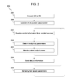
- FIG. 2 is a flowchart that schematically illustrates a method of controlled driving of LEDs, in accordance with an embodiment of the present invention.
- Embodiments of the present invention provide improved systems and methods for controlled driving of LEDs.
- the disclosed techniques help to provide efficient LED lighting in a given space, by controlling various LED driving parameters based on a variety of control sources, including sensors, which sense various environmental parameters such as lighting and motion in the vicinity of the LEDs.
- FIG. 1 there is shown a block diagram 104 of a controlled LED driver (CLD) operating within a lighting system 100 , in accordance with an embodiment of the present invention.
- CLD 104 is connected to an AC voltage 108 , which is, in an embodiment, a mains output.
- AC voltage 108 is an output of an external dimmer having a dimming angle.
- An AC/DC converter 112 converts AC voltage 108 to a DC voltage at its output.
- a LED drivers block 116 that follows, comprises one or more LED drivers, wherein each driver may constitute at its output either a voltage source or a current source.
- a V/I monitoring circuitry 120 that follows is explained below.
- a LEDs block 124 which is, in an embodiment, external to CLD 104 , typically comprises one or more LED chains coupled to LED drivers 116 and serve to provide lighting of a given space in the vicinity of LEDs 124 .
- a LED driver 116 outputs a pulsed output power whose duty-cycle is modulated by a Pulse Width Modulation (PWM) technique for achieving a required lighting intensity.
- PWM Pulse Width Modulation
- the amplitude of the pulsed output power is typically determined by LEDs 124 specification.
- V/I monitoring circuitry 120 coupled to LEDs 124 constitutes a monitoring means of the driving voltage and current supplied by each LED driver 116 to each LED chain 124 .
- a local controller 128 monitors and controls the operation of the aforementioned blocks through a control interface 130 .
- local controller 128 controls driving parameters of LEDs 124 , such as the duty-cycle and amplitude of the pulsed power at the output of each LED driver 116 , for achieving required lighting of LEDs 124 , based on control information received from various control sources that are described below.
- AC/DC converter 112 also constitutes a control source for local controller 128 by detecting the AC voltage dimming angle and providing this control information to local controller 128 through line 132 . The local controller then determines accordingly the duty-cycle at the output of LED drivers 116 .
- the local controller determines a maximum lighting intensity based on the dimming angle, so as to limit peak currents within AC/DC converter 112 .
- the control information flow on the inverse direction of line 132 serves local controller 128 for controlling the operation of AC/DC converter 112 , e.g. turning it to idle mode when no lighting power is required.
- one or more remote controllers 144 constitute a control source for local controller 128 via control interface 130 .
- remote controller 144 can be a smartphone, by which a user can command local controller 128 to turn on, turn off or dim LEDs 124 .
- a user, or a computer application in remote controller 144 can, in the same manner, command any other characteristics of LEDs 124 lighting, e.g. a resultant color, as explained below.
- a link 140 which connects remote controller 144 to local controller 128 through control interface 130 within CLD 104 , is typically a wireless link supporting one or more multiple access protocols. However, in some embodiments a wired link 140 may be used as well.
- link 140 is made bidirectional, thereby allowing local controller 128 to provide remote controller 144 with status information.
- status information typically comprises command acknowledgement, the dimming angle value if available, monitored parameters of the pulsed output power such as duty-cycle and amplitude, output signaling of control sources of local controller 128 , specifically output signaling of sensors which are described below and the like.
- remote controller 144 determines the maximum lighting intensity, based on the dimming angle, instead of local controller 128 .
- control interface 130 comprises an audio interface thereby allowing users to provide local controller 128 with control information in the form of vocal commands.
- the above audio interface is adapted to receive control information in the form of sounds, specifically music coming from a music player or from playing music instruments, while local controller 128 is configured to vary LEDs 124 driving parameters according to the music played.
- LEDs 124 are typically colored with various colors, and controller 128 varies the driving parameters at the output of LED drivers 116 so as to provide variable lighting color and intensity synchronized with the music played.
- various types of sensors are used as control sources for local controller 128 .
- Such sensors may be packaged within CLD 104 , as depicted by local sensors 136 in FIG. 1 , or located externally to the CLD as depicted by remote sensors 148 .
- Local sensors 136 typically pass their output signaling to control interface 130 through a wire connection.
- Remote sensors 148 are typically coupled to control interface 130 through wireless link 140 .
- a motion detection sensor indicates to local controller 128 , upon detecting motion, that it should intensify the lighting level of LEDs 124 through LED drivers 116 .
- a light detector sensor serves to measure and to indicate to local controller 128 the actual lighting intensity and optionally, the color of LEDs 124 . Local controller 128 then adjusts the driving parameters at the output of LED drivers 116 so as to achieve a required lighting based on the light detector output signaling.
- a remote sensor 148 can send its output signaling to any of the local and remote controllers 128 and 144 respectively, as shown in FIG. 1 .
- the choice of the specific signaling path determines the way each of the controllers handles the sensor's output signaling and, in general, the partition of intelligence between both controllers.
- a remote sensor 148 may be, for example, a photographic means such as a video camera.
- the video camera sends variable photographic information directly to local controller 128 as depicted by line 152 in FIG. 1 .
- This photographic information typically comprises a stream of photos of a space in the vicinity of LEDs 124 .
- a pattern recognition software within local controller 128 is programmed to apply lighting through LED drivers 116 , as explained above, to any part of the space upon detecting motion in that part.
- local controller 128 analyses the actual lighting in various parts of the space and adjusts LED drivers 116 to provide required lighting characteristics in those parts, based on the analysis.
- the video camera sends the above photo stream to remote controller 144 , as depicted by line 156 . In this case the above motion detection and/or lighting analysis is done in the remote controller. The remote controller then converts the analysis results to commands containing lighting parameters and sends these commands to local controller 128 through link 140 .
- local controller 128 typically comprises a programmable processor, which is programmed in software to carry out the functions described herein.
- Software updates as well as required lighting characteristics may be downloaded to local controller 128 through link 140 .
- link 140 comprises a secure access to avoid false or malicious control of CLD 104 .
- CLD 104 CLD 104 and lighting system 100 that are essential for understanding certain features of the disclosed techniques.
- Conventional elements of CLD 104 that are not needed for this understanding have been omitted from FIG. 1 for the sake of simplicity but will be apparent to persons of ordinary skill in the art.
- the configuration shown in FIG. 1 is an example configuration, which was chosen purely for the sake of conceptual clarity. In alternative embodiments, any other suitable configurations can also be used.
- FIG. 2 shows a flowchart 200 which schematically illustrates a method of controlled driving of LEDs, in accordance with an embodiment of the present invention.
- the flowchart begins with a converting step 204 , wherein AC/DC converter 112 converts AC voltage 108 to a DC voltage at its output.
- each LED driver 116 converts the DC voltage to a pulsed output power whose duty-cycle is modulated by a Pulse Width Modulation (PWM) technique for achieving a required lighting intensity.
- PWM Pulse Width Modulation
- local controller 128 receives control information from various controlled sources as described above.
- local controller 128 determines the lighting parameters, as duty cycle and intensity, of the pulsed output power at the outputs of LED drivers 116 for achieving a required lighting of LEDs 124 .
- V/I monitoring circuitry 120 monitor the driving voltages and currents supplied by LED drivers 116 to LEDs 124 .
- Local controller 128 adjusts, according the monitored values, the lighting parameters, which is depicted by a return loop from step 220 to step 216 .
- a sending step 224 local controller 128 sends status information, such as dimming angle, to remote controller 144 , which commands the local controller while taking into account this status information as explained above. This is depicted by a return loop from step 224 to step 212 .
- a sensing step 228 one or more sensors sense various parameters in the space to be lighted, as described above. The output signaling of these sensors constitutes part of the overall control information according to which local controller 128 controls LED drivers 116 . This is depicted by a return loop from step 228 to step 212 .
- FIG. 2 is an example flowchart, which was chosen purely for the sake of conceptual clarity. In alternative embodiments, any other suitable flowchart can also be used for illustrating the disclosed method. Method steps that are not mandatory for understanding the disclosed techniques were omitted from FIG. 2 for the sake of clarity.
Landscapes
- Circuit Arrangement For Electric Light Sources In General (AREA)
Abstract
Description
Claims (45)
Priority Applications (1)
| Application Number | Priority Date | Filing Date | Title |
|---|---|---|---|
| US14/201,967 US9282597B2 (en) | 2013-04-02 | 2014-03-10 | Device and method for controlled LED lighting |
Applications Claiming Priority (2)
| Application Number | Priority Date | Filing Date | Title |
|---|---|---|---|
| US201361807339P | 2013-04-02 | 2013-04-02 | |
| US14/201,967 US9282597B2 (en) | 2013-04-02 | 2014-03-10 | Device and method for controlled LED lighting |
Publications (2)
| Publication Number | Publication Date |
|---|---|
| US20140312782A1 US20140312782A1 (en) | 2014-10-23 |
| US9282597B2 true US9282597B2 (en) | 2016-03-08 |
Family
ID=51728495
Family Applications (1)
| Application Number | Title | Priority Date | Filing Date |
|---|---|---|---|
| US14/201,967 Active US9282597B2 (en) | 2013-04-02 | 2014-03-10 | Device and method for controlled LED lighting |
Country Status (1)
| Country | Link |
|---|---|
| US (1) | US9282597B2 (en) |
Families Citing this family (9)
| Publication number | Priority date | Publication date | Assignee | Title |
|---|---|---|---|---|
| SG2014003602A (en) * | 2014-01-16 | 2015-08-28 | Opulent Electronics Internat Pte Ltd | Dimmer system |
| JP6429146B2 (en) * | 2014-10-30 | 2018-11-28 | パナソニックIpマネジメント株式会社 | Lighting control method, lighting control system using the same, and lighting system |
| US9549446B2 (en) * | 2015-01-06 | 2017-01-17 | Kuo-Ching Chiang | Intelligent lighting apparatus |
| CN105188225A (en) * | 2015-09-30 | 2015-12-23 | 生迪智慧科技有限公司 | LED (Light Emitting Diode) driver and LED lamp |
| CN105592587B (en) * | 2015-12-12 | 2017-07-07 | 浙江凯耀照明股份有限公司 | The control method of LED |
| US9655188B1 (en) * | 2016-02-03 | 2017-05-16 | Ketra, Inc. | Illumination device and method for independently controlling power delivered to a load from dimmers having dissimilar phase-cut dimming angles |
| US10736187B2 (en) | 2016-02-03 | 2020-08-04 | Lutron Ketra, Llc | Illumination device and method for decoupling power delivered to an LED load from a phase-cut dimming angle |
| US9655178B1 (en) | 2016-02-03 | 2017-05-16 | Ketra, Inc. | Device and method for removing transient and drift from an AC main supplied to a DC-controlled LED load |
| CN114080078B (en) * | 2020-08-10 | 2024-02-20 | 苏州斯特雷电子有限公司 | Intelligent driver and driving method for LED lamp strip |
Citations (10)
| Publication number | Priority date | Publication date | Assignee | Title |
|---|---|---|---|---|
| US20040085030A1 (en) * | 2002-10-30 | 2004-05-06 | Benoit Laflamme | Multicolor lamp system |
| US20060261754A1 (en) * | 2005-05-18 | 2006-11-23 | Samsung Electro-Mechanics Co., Ltd. | LED driving circuit having dimming circuit |
| US20070206370A1 (en) | 2006-03-05 | 2007-09-06 | Paul Crunk | Low Power LED-Fluorescent Lighting System |
| US20090302783A1 (en) | 2008-06-10 | 2009-12-10 | Chien-Lung Wang | Led illumination system with multiple independent loops |
| US20100244727A1 (en) | 2009-03-25 | 2010-09-30 | Seoul Semiconductor Co., Ltd | Light-emitting diode driver |
| US20120181935A1 (en) * | 2009-09-04 | 2012-07-19 | American Dj Supply, Inc. | Wireless controller for lighting system |
| US20120293083A1 (en) | 2004-02-25 | 2012-11-22 | Lynk Labs, Inc. | High Frequency Multi-Voltage And Multi-Brightness LED Lighting Devices And Systems And Methods Of Using Same |
| US20130069561A1 (en) * | 2011-03-24 | 2013-03-21 | Cirrus Logic, Inc. | Color mixing of electronic light sources with correlation between phase-cut dimmer angle and predetermined black body radiation function |
| US20130175931A1 (en) * | 2012-01-05 | 2013-07-11 | Laurence P. Sadwick | Triac Dimming Control System |
| US20130307434A1 (en) * | 2012-05-21 | 2013-11-21 | Marvell World Trade Ltd. | Method and apparatus for controlling a lighting device |
-
2014
- 2014-03-10 US US14/201,967 patent/US9282597B2/en active Active
Patent Citations (10)
| Publication number | Priority date | Publication date | Assignee | Title |
|---|---|---|---|---|
| US20040085030A1 (en) * | 2002-10-30 | 2004-05-06 | Benoit Laflamme | Multicolor lamp system |
| US20120293083A1 (en) | 2004-02-25 | 2012-11-22 | Lynk Labs, Inc. | High Frequency Multi-Voltage And Multi-Brightness LED Lighting Devices And Systems And Methods Of Using Same |
| US20060261754A1 (en) * | 2005-05-18 | 2006-11-23 | Samsung Electro-Mechanics Co., Ltd. | LED driving circuit having dimming circuit |
| US20070206370A1 (en) | 2006-03-05 | 2007-09-06 | Paul Crunk | Low Power LED-Fluorescent Lighting System |
| US20090302783A1 (en) | 2008-06-10 | 2009-12-10 | Chien-Lung Wang | Led illumination system with multiple independent loops |
| US20100244727A1 (en) | 2009-03-25 | 2010-09-30 | Seoul Semiconductor Co., Ltd | Light-emitting diode driver |
| US20120181935A1 (en) * | 2009-09-04 | 2012-07-19 | American Dj Supply, Inc. | Wireless controller for lighting system |
| US20130069561A1 (en) * | 2011-03-24 | 2013-03-21 | Cirrus Logic, Inc. | Color mixing of electronic light sources with correlation between phase-cut dimmer angle and predetermined black body radiation function |
| US20130175931A1 (en) * | 2012-01-05 | 2013-07-11 | Laurence P. Sadwick | Triac Dimming Control System |
| US20130307434A1 (en) * | 2012-05-21 | 2013-11-21 | Marvell World Trade Ltd. | Method and apparatus for controlling a lighting device |
Also Published As
| Publication number | Publication date |
|---|---|
| US20140312782A1 (en) | 2014-10-23 |
Similar Documents
| Publication | Publication Date | Title |
|---|---|---|
| US9282597B2 (en) | Device and method for controlled LED lighting | |
| US8258707B2 (en) | Lighting device with a LED used for sensing | |
| JP5475798B2 (en) | Illumination apparatus and method for embedding a data signal in a luminance output using an AC drive light source | |
| JP4676494B2 (en) | Illumination light communication apparatus, illumination light communication method, and computer program | |
| US9313855B1 (en) | Intelligent lighting system and integrated circuit for determining ambient light intensity | |
| JP4470787B2 (en) | Lighting system | |
| JP2014517451A5 (en) | ||
| US8319441B2 (en) | Road lamp dimming control device | |
| TWI392399B (en) | Light adjusting device for a light emitting diode and related light adjusting method and light emitting device | |
| JP2012226839A (en) | Load control system | |
| JP2008206087A (en) | Visible optical communication system | |
| US8878457B2 (en) | Adaptable lighting system | |
| US9345088B2 (en) | LED control circuits and methods | |
| US9668326B2 (en) | Light fixture with multiple dimming capabilities | |
| KR101232304B1 (en) | power supply control apparatus for lighting | |
| US9226367B1 (en) | Method and apparatus for light control and ambient light detection using an LED light fixture | |
| US9763304B2 (en) | Visible light communication apparatus and method for manufacturing visible light communication apparatus | |
| JP6170995B2 (en) | Power supply circuit for lighting equipment | |
| KR20100043479A (en) | Power supply for driving led | |
| US20150028757A1 (en) | Single wire lighting driver control | |
| KR101318270B1 (en) | Led lighting controlling device equipped with gradually output brightness change function | |
| US9101002B2 (en) | Method of controlling multiple lamps | |
| US20150223307A1 (en) | Theatrical effects controller with ultrasonic output | |
| KR20190115482A (en) | Wireless control apparatus of internet of things smart light emitting diode streetlamp apparatus equipped with situation detection fuction method thereof | |
| KR101318271B1 (en) | Led lighting controlling method equipped with gradually output brightness change function |
Legal Events
| Date | Code | Title | Description |
|---|---|---|---|
| AS | Assignment |
Owner name: ROMANO, SHAFRIR, ISRAEL Free format text: ASSIGNMENT OF ASSIGNORS INTEREST;ASSIGNOR:MAGNITUDE LIGHTING TRANSFORMERS INC.;REEL/FRAME:032410/0427 Effective date: 20140312 |
|
| AS | Assignment |
Owner name: MAGNITUDE HOLDINGS LTD., A BERMUDA EXEMPT COMPANY Free format text: ASSIGNMENT OF ASSIGNORS INTEREST;ASSIGNOR:ROMANO, SHAFRIR;REEL/FRAME:036309/0541 Effective date: 20150714 |
|
| STCF | Information on status: patent grant |
Free format text: PATENTED CASE |
|
| MAFP | Maintenance fee payment |
Free format text: PAYMENT OF MAINTENANCE FEE, 4TH YR, SMALL ENTITY (ORIGINAL EVENT CODE: M2551); ENTITY STATUS OF PATENT OWNER: SMALL ENTITY Year of fee payment: 4 |
|
| MAFP | Maintenance fee payment |
Free format text: PAYMENT OF MAINTENANCE FEE, 8TH YR, SMALL ENTITY (ORIGINAL EVENT CODE: M2552); ENTITY STATUS OF PATENT OWNER: SMALL ENTITY Year of fee payment: 8 |