US8996072B2 - Method and apparatus for controlling light emitting elements in terminal device and terminal device - Google Patents
Method and apparatus for controlling light emitting elements in terminal device and terminal device Download PDFInfo
- Publication number
- US8996072B2 US8996072B2 US14/065,567 US201314065567A US8996072B2 US 8996072 B2 US8996072 B2 US 8996072B2 US 201314065567 A US201314065567 A US 201314065567A US 8996072 B2 US8996072 B2 US 8996072B2
- Authority
- US
- United States
- Prior art keywords
- light intensity
- intensity value
- value
- terminal device
- image capturing
- Prior art date
- Legal status (The legal status is an assumption and is not a legal conclusion. Google has not performed a legal analysis and makes no representation as to the accuracy of the status listed.)
- Active
Links
Images


Classifications
-
- H—ELECTRICITY
- H04—ELECTRIC COMMUNICATION TECHNIQUE
- H04M—TELEPHONIC COMMUNICATION
- H04M1/00—Substation equipment, e.g. for use by subscribers
- H04M1/02—Constructional features of telephone sets
- H04M1/0295—Mechanical mounting details of display modules
-
- G—PHYSICS
- G09—EDUCATION; CRYPTOGRAPHY; DISPLAY; ADVERTISING; SEALS
- G09G—ARRANGEMENTS OR CIRCUITS FOR CONTROL OF INDICATING DEVICES USING STATIC MEANS TO PRESENT VARIABLE INFORMATION
- G09G5/00—Control arrangements or circuits for visual indicators common to cathode-ray tube indicators and other visual indicators
- G09G5/10—Intensity circuits
-
- G—PHYSICS
- G06—COMPUTING; CALCULATING OR COUNTING
- G06F—ELECTRIC DIGITAL DATA PROCESSING
- G06F1/00—Details not covered by groups G06F3/00 - G06F13/00 and G06F21/00
- G06F1/26—Power supply means, e.g. regulation thereof
- G06F1/32—Means for saving power
- G06F1/3203—Power management, i.e. event-based initiation of a power-saving mode
- G06F1/3234—Power saving characterised by the action undertaken
- G06F1/325—Power saving in peripheral device
- G06F1/3265—Power saving in display device
-
- H—ELECTRICITY
- H04—ELECTRIC COMMUNICATION TECHNIQUE
- H04M—TELEPHONIC COMMUNICATION
- H04M1/00—Substation equipment, e.g. for use by subscribers
- H04M1/02—Constructional features of telephone sets
- H04M1/22—Illumination; Arrangements for improving the visibility of characters on dials
-
- H—ELECTRICITY
- H04—ELECTRIC COMMUNICATION TECHNIQUE
- H04W—WIRELESS COMMUNICATION NETWORKS
- H04W52/00—Power management, e.g. TPC [Transmission Power Control], power saving or power classes
- H04W52/02—Power saving arrangements
- H04W52/0209—Power saving arrangements in terminal devices
- H04W52/0261—Power saving arrangements in terminal devices managing power supply demand, e.g. depending on battery level
- H04W52/0267—Power saving arrangements in terminal devices managing power supply demand, e.g. depending on battery level by controlling user interface components
- H04W52/027—Power saving arrangements in terminal devices managing power supply demand, e.g. depending on battery level by controlling user interface components by controlling a display operation or backlight unit
-
- H—ELECTRICITY
- H04—ELECTRIC COMMUNICATION TECHNIQUE
- H04M—TELEPHONIC COMMUNICATION
- H04M2250/00—Details of telephonic subscriber devices
- H04M2250/12—Details of telephonic subscriber devices including a sensor for measuring a physical value, e.g. temperature or motion
-
- H—ELECTRICITY
- H04—ELECTRIC COMMUNICATION TECHNIQUE
- H04M—TELEPHONIC COMMUNICATION
- H04M2250/00—Details of telephonic subscriber devices
- H04M2250/52—Details of telephonic subscriber devices including functional features of a camera
-
- H—ELECTRICITY
- H04—ELECTRIC COMMUNICATION TECHNIQUE
- H04N—PICTORIAL COMMUNICATION, e.g. TELEVISION
- H04N23/00—Cameras or camera modules comprising electronic image sensors; Control thereof
- H04N23/70—Circuitry for compensating brightness variation in the scene
- H04N23/74—Circuitry for compensating brightness variation in the scene by influencing the scene brightness using illuminating means
-
- Y02B60/1242—
-
- Y—GENERAL TAGGING OF NEW TECHNOLOGICAL DEVELOPMENTS; GENERAL TAGGING OF CROSS-SECTIONAL TECHNOLOGIES SPANNING OVER SEVERAL SECTIONS OF THE IPC; TECHNICAL SUBJECTS COVERED BY FORMER USPC CROSS-REFERENCE ART COLLECTIONS [XRACs] AND DIGESTS
- Y02—TECHNOLOGIES OR APPLICATIONS FOR MITIGATION OR ADAPTATION AGAINST CLIMATE CHANGE
- Y02D—CLIMATE CHANGE MITIGATION TECHNOLOGIES IN INFORMATION AND COMMUNICATION TECHNOLOGIES [ICT], I.E. INFORMATION AND COMMUNICATION TECHNOLOGIES AIMING AT THE REDUCTION OF THEIR OWN ENERGY USE
- Y02D10/00—Energy efficient computing, e.g. low power processors, power management or thermal management
-
- Y—GENERAL TAGGING OF NEW TECHNOLOGICAL DEVELOPMENTS; GENERAL TAGGING OF CROSS-SECTIONAL TECHNOLOGIES SPANNING OVER SEVERAL SECTIONS OF THE IPC; TECHNICAL SUBJECTS COVERED BY FORMER USPC CROSS-REFERENCE ART COLLECTIONS [XRACs] AND DIGESTS
- Y02—TECHNOLOGIES OR APPLICATIONS FOR MITIGATION OR ADAPTATION AGAINST CLIMATE CHANGE
- Y02D—CLIMATE CHANGE MITIGATION TECHNOLOGIES IN INFORMATION AND COMMUNICATION TECHNOLOGIES [ICT], I.E. INFORMATION AND COMMUNICATION TECHNOLOGIES AIMING AT THE REDUCTION OF THEIR OWN ENERGY USE
- Y02D30/00—Reducing energy consumption in communication networks
- Y02D30/70—Reducing energy consumption in communication networks in wireless communication networks
Definitions
- the present invention relates to the field of technologies for controlling light emitting elements, and in particular, to a method and an apparatus for controlling light emitting elements in a terminal device, and a terminal device.
- An ambient light sensor can measure and capture illumination intensity of current ambient light, and can adjust luminance of various light emitting elements automatically according to the illumination intensity, optimize luminance control, and reduce power consumption of products.
- Common light emitting elements include a display screen, a keyboard backlight, and so on.
- electricity consumed by a display is up to 30% of the total capacity of the battery.
- An ambient light sensor can detect the brightness and darkness of the environment, and the mobile phone may reduce luminance of the display in a relatively dark environment to reduce power consumption and prolong the service time of the battery as much as possible.
- An ambient light sensor needs to convert received optical signals into electrical signals so as to implement the functions of a light sensor. Therefore, a terminal device needs to provide a photosensitive zone for the ambient light sensor. For example, by forming a hole on the terminal device or other means, light can be irradiated to the ambient light sensor.
- some terminal devices nowadays become increasingly smaller and thinner. In this case, it is necessary to utilize every tiny space. Therefore, the ambient light sensor is relatively simple, and the photosensitive zone provided on the terminal device for it is very small, which, however, will bring adverse effects.
- the effective exposure area of the ambient light sensor is generally a few tenths of a millimeter.
- the mobile phone has dust that just covers the effective exposure area of the ambient light sensor due to improper sealing, or a fingerprint of the user just covers the effective exposure area of the ambient light sensor, the amount of incident ambient light may be affected, so that the amount of the ambient light actually irradiated onto the effective exposure area of the ambient light sensor may be greatly reduced, which leads to an increased recognition error, and may further affect the effectiveness of the terminal device in controlling light emitting elements (including the display screen, the keyboard backlight, and so on).
- the present invention provides a method and an apparatus for controlling light emitting elements in a terminal device and a terminal device to improve effectiveness of controlling the light emitting elements.
- the present invention provides the following solutions:
- a method for controlling light emitting elements in a terminal device includes:
- An apparatus for controlling light emitting elements in a terminal device includes:
- an obtaining unit configured to obtain a first light intensity value detected by an ambient light sensor in a terminal device and obtain a second light intensity value detected by an image capturing apparatus in the terminal device under same lighting conditions
- a standard value determining unit configured to determine a standard light intensity value corresponding to the second light intensity value, which is obtained by the obtaining unit, according to a preset mapping between the second light intensity value and a standard light intensity value of the ambient light sensor;
- a calibration parameter obtaining unit configured to obtain a calibration parameter for the ambient light sensor according to the first light intensity value obtained by the obtaining unit and the standard light intensity value determined by the standard value determining unit;
- a detected value obtaining unit configured to obtain a detected light intensity value detected by the ambient light sensor when light emitting elements in the terminal device need to be controlled
- a controlling unit configured to control the light emitting elements in the terminal device according to the detected light intensity value detected by the detected value obtaining unit and the calibration parameter obtained by the calibration parameter obtaining unit.
- a terminal device includes an image capturing apparatus, an ambient light sensor, light emitting elements, and the aforesaid apparatus for controlling light emitting elements, where:
- the image capturing apparatus is configured to collect image information through a camera, and send the image information to the apparatus for controlling light emitting elements;
- the ambient light sensor is configured to detect ambient light, convert an optical signal of the ambient light into an electrical signal, and send the electrical signal to the apparatus for controlling light emitting elements;
- the light emitting elements are configured to emit visible light or display visible content.
- the present invention discloses the following technical effects:
- an image capturing apparatus in a terminal device may be used to detect a light intensity value, and a calibration parameter for an ambient light sensor may be obtained with reference to a light intensity value detected by the ambient light sensor.
- the detected light intensity value may be corrected with a calibration parameter, and then the corrected light intensity value may be used to control the light emitting element in the terminal device. Because the light intensity value detected by the ambient light sensor is calibrated with the light intensity information obtained by the image capturing apparatus, the accuracy of the light intensity value for controlling the light emitting element can be improved, thereby improving the effectiveness of controlling the light emitting element.
- FIG. 1 is a flowchart of a method for controlling light emitting elements in a terminal device according to an embodiment of the present invention
- FIG. 2 is a schematic structural diagram of an image capturing apparatus
- FIG. 3 is a schematic diagram of an apparatus for controlling light emitting elements in a terminal device according to an embodiment of the present invention.
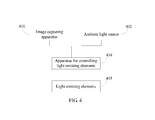
- FIG. 4 is a schematic diagram of a terminal device according to an embodiment of the present invention.
- a method for controlling light emitting elements in a terminal device includes the following steps:
- an image capturing apparatus is generally installed in addition to the ambient light sensor.
- a mobile phone as an example of the terminal device, most mobile phones nowadays have a photographing function, which requires installation of an image capturing apparatus, such as a camera.
- the image capturing apparatus is also based on the principle of converting an optical signal into an electrical signal and also can detect light intensity information. Therefore, the image capturing apparatus may be regarded as another form of an ambient light sensing apparatus to some extent.
- the photosensitive zone of an image capturing apparatus does not easily fail due to interference or slight obstruction. Therefore, such a characteristic of the image capturing apparatus is used in the embodiment of the present invention. It is assumed that the interference received by the image capturing apparatus from external pollutants is ignorable, and that the ambient light sensor is calibrated by using the ambient light intensity value captured by the image capturing apparatus.
- the standard circumstances refer to the same lighting conditions, that is, the intensity of light irradiated onto the ambient light sensor and the image capturing apparatus (for example, in an outdoor environment) is the same, and the photosensitive zone of the ambient light sensor is free from interference caused by external pollutants or other obstacles. That is, under the standard circumstances, the image capturing apparatus may detect a light intensity value, and correspondingly, the ambient light sensor may also detect a light intensity value. Moreover, under such standard circumstances, because the ambient light sensor is free from interference of external pollutants, the light intensity value detected by the ambient light sensor may be regarded as a standard light intensity value.
- the same lighting conditions refer to the same (for example, in an outdoor environment) or similar (for example, when facing the same light source that produces no obvious brightness or darkness difference) intensity of light irradiated onto the ambient light sensor and the image capturing apparatus.
- the standard light intensity value may be obtained in advance, and when the ambient light sensor needs to be calibrated, the parameter is known and can be directly used. The method for obtaining the standard light intensity value will be detailed later.
- Steps S 101 -S 103 above are equivalent to a calibration procedure in the terminal device.
- the calibration procedure may be started in different ways.
- the terminal device may start the calibration procedure at regular intervals, or the user performs manual control, and so on. Every time when a light emitting element is controlled after a calibration procedure is completed, the calibration parameter obtained in the calibration procedure may be used to exercise control.
- the control on the light emitting elements includes adjustment of the display screen luminance and keyboard backlight, and so on.
- a detected light intensity value still needs to be detected by the ambient light sensor.
- the detected light intensity value is detected by the ambient light sensor, and may be inaccurate because the photosensitive zone of the ambient light sensor may have been obstructed by dust or a fingerprint. It may be inaccurate if the detected light intensity value is directly used for controlling the light emitting element of the terminal device.
- the photosensitive zone of an ambient light sensor is obstructed by dust, and a detected light intensity value detected by the sensor is x, but in fact, the current ambient light intensity can be truly reflected only when the light intensity value is Z, where Z is greater than x.
- the detected light intensity value x is directly used for adjusting the display screen luminance, the adjusted luminance may fail to match the actual ambient light intensity, thereby failing to produce a cozy picture.
- the calibration parameter for the ambient light sensor has been obtained. Therefore, on an occasion of controlling a light emitting element, after a detected light intensity value detected by the ambient light sensor is obtained, the detected light intensity value may be corrected with the calibration parameter first so as to obtain a corrected light intensity value, and then the corrected light intensity value may be used to control the light emitting element, thereby improving effectiveness of controlling the light emitting element.
- the terminal device also needs to provide a photosensitive zone for the image capturing apparatus; moreover, because the image capturing apparatus needs to collect a lot of information, the area of the photosensitive zone set for the image capturing apparatus on the terminal device is generally far greater than the photosensitive zone set for the ambient light sensor. Because the photosensitive zone of the image capturing apparatus is relatively large, the image capturing apparatus imposes less strict requirements on the environment than the ambient light sensor, and slight obstruction caused by dust or a fingerprint will not produce a great impact on the incident light intensity. Therefore, the light intensity information obtained by the image capturing apparatus is generally accurate, and is suitable for calibrating the light intensity value detected by the ambient light sensor to improve accuracy of the light intensity value used for controlling the light emitting element, thereby improving effectiveness of controlling the light emitting element.
- the embodiment of the present invention can use an image capturing apparatus to calibrate a light intensity value detected by an ambient light sensor.
- the photosensitive zone of the image capturing apparatus may be greater than the photosensitive zone of the ambient light sensor.
- the image capturing apparatus generally includes three parts: a lens LENS, a filter, and an optoelectronic element.
- LENS The imaging of the image capturing apparatus is primarily attributable to the optoelectronic element. To increase the lighting rate of the optoelectronic element, it is necessary to expand the photoreception area of a single pixel. While the lighting rate is increased, the picture quality deteriorates. LENS is equivalent to a lens added before the optoelectronic element, the lighting rate of the optoelectronic element does not depend on the opening area of the optoelectronic element, but depends on the surface area of the LENS.
- Filter Almost all colors recognizable by human eyes can be formed by three primary colors, red (R), green (G), and blue (B). Therefore, the filter primarily uses an RGB tricolor separation method, that is, color modulation is performed by using three channels, R, G, and B.
- the optoelectronic element converts a light source that penetrates the filter into an electrical signal, quantizes the electrical signal and transmits it to an image processing chip, and restores the image through a series of transformation, processing, modulation, and so on.
- the image capturing apparatus can also detect the ambient light intensity, because the basic function of the image capturing apparatus is to capture images, the image information obtained by the apparatus is generally an RGB component of an image, which is another manner of representing an optical signal. Therefore, in order to obtain the second light intensity value required by the embodiment of the present invention from the image capturing apparatus, the image information obtained by the image capturing apparatus may be processed first.
- the image capturing apparatus generally uses a quantized RGB vector space to represent signal intensity of each color component.
- a quantized RGB vector space to represent signal intensity of each color component.
- 8-bit binary data is used to express a component, and therefore there may be 256 levels. That is, the information obtained by the image capturing apparatus is an RGB component of each pixel, and the image processing chip can restore the color of each pixel according to the RGB component of each pixel.
- YUV vector space representation method where, Y represents luminance (Luminance), U represents chrominance (Chrominance), and V represents chroma (Chroma).
- Y component that represents luminance actually can represent light intensity information.
- RGB vector space and the YUV vector space are different ways of representing light information
- the two vector spaces can be converted to each other.
- an empiric formula for converting an RGB vector space into a YUV vector space is:
- a Y value that is, a luminance value
- the processing of the image information obtained by the image capturing apparatus may be:
- the value may be directly converted into a light intensity value, and the converted light intensity value may be used directly as a light intensity value detected by the image capturing apparatus. If RGB component values of multiple pixels are read, the RGB component value of each pixel may be converted into a light intensity value first, and then an average value of all light intensity values may be calculated, and the average value may be used as a light intensity value detected by the image capturing apparatus.
- RGB component values of multiple pixels may be read, an average value of the RGB component values of the multiple pixels may be calculated first, and then a light intensity value corresponding to the average value of the RGB component values of the multiple pixels may be calculated, and the corresponding light intensity value may be used as a light intensity value detected by the image capturing apparatus.
- the RGB values P1 (r1, g1, b1), P2 (r2, g2, b2), and P3 (r3, g3, b3) of three pixels P1, P2, and P3 are read, the average value
- RGB component values may be converted into a light intensity value according to formula (2).
- an image collected by the image capturing apparatus has numerous pixels, as regards which specific pixel will be selected for reading, no restriction may be set.
- multiple zones may be set in the image collected by the image capturing apparatus, and the RGB component values of multiple pixels are read from each zone respectively.
- a central zone of the collected image generally has a better collection effect. Therefore, for measurement precision, the RGB component value of one or more pixels may be read from the central zone of the image collected by the image capturing apparatus.
- the RGB component values of several pixels centered on an optoelectronic element may be collected, and the Y value corresponding to each of them is calculated, and then an average value of the Y values is used as a light intensity value detected by the image capturing apparatus.
- a mapping between the light intensity value detected by the ambient light sensor and the light intensity value detected by the image capturing apparatus may be obtained first under standard circumstances.
- the standard circumstances refer to the same lighting conditions, that is, the intensity of light irradiated onto the ambient light sensor and the image capturing apparatus (for example, in an outdoor environment) is the same, and the photosensitive zone of the ambient light sensor is free from obstruction.
- light intensity sampling may be performed by turning on the ambient light sensor and the image capturing apparatus simultaneously under the same lighting conditions. It is assumed that the light intensity sample value collected by the ambient light sensor is a, and that the light intensity sample value collected by the image capturing apparatus is A (which may be obtained by converting the RGB component value into a Y value, as described earlier). In this way, a and A may form a two-dimensional vector.
- the two-dimensional vector may represent a mapping between a quantized value of the light intensity collected by the ambient light sensor and a quantized value of the light intensity collected by the image capturing apparatus under standard circumstances.
- a table of two-dimensional vectors may be generated for continuously changing ambient light intensity according to a linear change relationship of the two quantized values, as shown in Table 1:
- the Y value is generally expressed by 8-bit binary data, there may be 256 levels. That is, the light intensity value A detected by the image capturing apparatus may have 256 levels. In Table 1, there may be 256 two-dimensional vectors, representing 256 types of light intensity. Alternatively, when the Y value is expressed by other means, such as 16-bit binary data, the maximum light intensity level that can be expressed in Table 1 may be different.
- the data in Table 1 may be fixed into the terminal device as standard data to which reference may be made during calibration.
- the standard data may be obtained for each different terminal device in the way described above, and therefore, each terminal device may use its own standard data for calibrating the ambient light sensor, which leads to high accuracy.
- the standard data is not necessarily obtained for each terminal device respectively.
- the standard data may be used as standard data of the batch of terminal devices, and so on.
- the terminal device for which the standard data is obtained, can use the standard data to calibrate the ambient light sensor.
- the calibration procedure may be started automatically at regular intervals, or started by the user manually, or started automatically whenever the terminal device is started, and so on.
- the image capturing apparatus may be turned on automatically. Meanwhile, the user may be reminded to put the terminal device into a better illuminated place to ensure that the intensity of light irradiated onto the ambient light sensor and the image capturing apparatus is the same, for example, in an outdoor environment.
- the color (RGB) component values of several pixels collected by the image capturing apparatus may be read, and the Y value corresponding to each pixel may be calculated by using formula (2), and then an average value of the Y values may be used as a component value collected by the image capturing apparatus for representing the light intensity.
- the data x collected by the ambient light sensor is read, and the two make up a two-dimensional vector (x, Y). It can be seen that, the method for obtaining the two-dimensional vector (x, Y) is the same as the method for obtaining the two-dimensional vector (a, A) in Table 1; if the ambient light sensor is free from obstruction, (x, Y) should be a vector among the two-dimensional vectors in Table 1.
- (x, Y) is not a vector among the two-dimensional vectors in Table 1, it indicates that the ambient light sensor may be obstructed and needs to be calibrated. Therefore, after the two-dimensional vector (x, Y) is obtained, it may be compared with each two-dimensional vector in Table 1 to judge whether the two-dimensional vector (x, Y) exists in Table 1; if the two-dimensional vector exists, the ambient light sensor does not need to be calibrated; otherwise, if the two-dimensional vector does not exist, it indicates that the ambient light sensor needs to be calibrated.
- the two-dimensional vector (x, Y) does not exist in Table 1” means that the light intensity value detected by the ambient light sensor corresponding to the Y value in Table 1 should be a m , where a m is unequal to x; moreover, the inequality is caused by reduced incident light in the case that the ambient light sensor receives interference from external pollutants. Therefore, a m should be greater than x.
- the retrieved data may be added to the calibration parameter to act as an adjusted light intensity value, and the adjusted light intensity value is delivered to an upper-layer management program (such as a light emitting element management program), thereby ensuring that the upper-layer management program uses a more accurate ambient light intensity value to perform corresponding control operations, and improving effectiveness of the control operations.
- an upper-layer management program such as a light emitting element management program
- an apparatus for controlling light emitting elements in a terminal device is further provided by an embodiment of the present invention.
- the apparatus includes:
- an obtaining unit 301 configured to obtain a first light intensity value detected by an ambient light sensor in a terminal device and obtain a second light intensity value detected by an image capturing apparatus in the terminal device under same lighting conditions;
- the photosensitive zone of the image capturing apparatus may be greater than the photosensitive zone of the ambient light sensor
- a standard value determining unit 302 configured to determine a standard light intensity value corresponding to the second light intensity value according to a preset mapping between the second light intensity value and a standard light intensity value of the ambient light sensor;
- a calibration parameter obtaining unit 303 configured to obtain a calibration parameter for the ambient light sensor according to the first light intensity value obtained by the obtaining unit 301 and the standard light intensity value determined by the standard value determining unit 302 ;
- a detected value obtaining unit 304 configured to obtain a detected light intensity value detected by the ambient light sensor when light emitting elements in the terminal device need to be controlled;
- a controlling unit 305 configured to control the light emitting elements in the terminal device according to the detected light intensity value detected by the detected value obtaining unit 304 and the calibration parameter obtained by the calibration parameter obtaining unit 303 .
- the obtaining unit 301 may include:
- a reading subunit configured to read a color component value of an image from image information collected by the image capturing apparatus
- a converting subunit configured to convert the read color component value into a light intensity value according to a relationship between the color component value and the light intensity value, and determine, according to the converted light intensity value, the second light intensity value detected by the image capturing apparatus.
- the reading subunit may be specifically configured to:
- the reading subunit may be specifically configured to read color component values of multiple pixels from a central zone of an image collected by the image capturing apparatus, and use an average value of the color component values of the multiple pixels as a color component value of the image;
- the reading subunit may be specifically configured to respectively read color component values of multiple pixels from multiple preset zones of an image collected by the image capturing apparatus, and use an average value of the color component values of the multiple pixels as a color component value of the image.
- controlling unit 305 may include:
- a light intensity correcting subunit configured to add the detected light intensity value to the calibration parameter to obtain a corrected light intensity value, where the calibration parameter is a difference between the standard light intensity value and the first light intensity value;
- a controlling subunit configured to adjust luminance and/or display content of a light emitting element in the terminal device according to the corrected light intensity value.
- the apparatus may further include:
- a starting unit configured to compare the obtained first light intensity value and second light intensity value against a preset mapping, and when a value corresponding to the second light intensity value in the mapping is unequal to the first light intensity value, start the standard value determining unit 302 to perform an operation of determining the standard light intensity value corresponding to the second light intensity value.
- an image capturing apparatus in the terminal device may be used to detect a light intensity value, a light intensity value detected by an ambient light sensor is calibrated, and a calibration parameter for the ambient light sensor is obtained.
- the detected light intensity value may be corrected with a calibration parameter, and then the corrected light intensity value is used to control the light emitting element in the terminal device.
- the terminal device also needs to provide a photosensitive zone for the image capturing apparatus; moreover, because the image capturing apparatus needs to collect a lot of information, the area of the photosensitive zone set for the image capturing apparatus on the terminal device is generally far greater than the photosensitive zone set for the ambient light sensor. Because the photosensitive zone of the image capturing apparatus is relatively large, the image capturing apparatus imposes less strict requirements on the environment than the ambient light sensor, and slight obstruction caused by dust or a fingerprint will not produce a great impact on the incident light intensity. Therefore, the light intensity information obtained by the image capturing apparatus is generally accurate, and is suitable for calibrating the light intensity value detected by the ambient light sensor to improve accuracy of the light intensity value used for controlling the light emitting element, thereby improving effectiveness of controlling the light emitting element.
- the terminal device may include: an image capturing apparatus 401 , an ambient light sensor 402 , light emitting elements 403 , and an apparatus for controlling light emitting elements as described in the preceding embodiment.
- the image capturing apparatus 401 is configured to collect image information through a camera, and send the image information to the apparatus 404 for controlling light emitting elements.
- the ambient light sensor 402 is configured to detect ambient light, convert an optical signal of the ambient light into an electrical signal, and send the electrical signal to the apparatus 404 for controlling light emitting elements.
- the light emitting elements 403 are configured to emit visible light or display visible content.
- the terminal device may be a mobile phone, a man-machine interaction terminal, an electronic book reader, or another terminal device with a display function.
- the light emitting elements 403 may include one or a combination of several of the following: a display screen, a keyboard backlight, and an indicator.
- the mobile phone may further include a radio frequency circuit, a microphone, a speaker, and a power supply to perform basic functions of the mobile phone. The following describes the radio frequency circuit, the microphone, the speaker, and the power supply respectively.
- the radio frequency circuit is primarily configured to set up communication between the mobile phone and a wireless network, and implement receiving and sending of data between the mobile phone and the wireless network;
- the microphone is configured to collect sound and convert the collected sound into sound data, so that the mobile phone sends the sound data to the wireless network through the radio frequency circuit;
- the speaker is configured to restore sound from sound data received by the mobile phone from the wireless network through the radio frequency circuit, and play the sound to a user;
- the power supply is primarily configured to power each circuit or element of the mobile phone to ensure normal working of the mobile phone.
- the photosensitive zone of the image capturing apparatus 401 may be greater than the photosensitive zone of the ambient light sensor 402 .
- the embodiment of the apparatus for controlling light emitting elements and the embodiment of the terminal device correspond to the embodiment of the method for controlling light emitting elements described earlier. Therefore, for the part that is not detailed, reference may be made to the description in the method embodiment, and no repeated description is given herein.
- the program may be stored in a computer readable storage medium.
- the following steps are included: obtaining a first light intensity value detected by an ambient light sensor in a terminal device and obtaining a second light intensity value detected by an image capturing apparatus in the terminal device under same lighting conditions; determining a standard light intensity value corresponding to the second light intensity value according to a preset mapping between a light intensity value of the image capturing apparatus and a standard light intensity value of the ambient light sensor; obtaining a calibration parameter for the ambient light sensor according to the first light intensity value and the standard light intensity value; obtaining a detected light intensity value detected by the ambient light sensor when light emitting elements in the terminal device need to be controlled; and controlling the light emitting elements in the terminal device according to the detected light intensity value and the calibration parameter.
- the storage medium may be a ROM/RAM, a magnetic disk, an optical disk, and so on
Abstract
Description
Y=0.299R+0.578G+0.114B (2)
of the RGB component values of the three pixels is obtained, and then the average value
of the RGB component values may be converted into a light intensity value according to formula (2).
| TABLE 1 | |||||||
| Light Intensity Value Detected | a1 | a2 | a3 | . . . | an | an+1 | . . . |
| by Ambient Light Sensor (a) | |||||||
| Light Intensity Value Detected | A1 | A2 | A3 | . . . | An | An+1 | . . . |
| by Image Capturing Apparatus (A) | |||||||
Claims (14)
Applications Claiming Priority (1)
| Application Number | Priority Date | Filing Date | Title |
|---|---|---|---|
| PCT/CN2011/073507 WO2011137731A2 (en) | 2011-04-29 | 2011-04-29 | Method for controlling light-emitting device in terminal equipment, apparatus thereof and terminal equipment |
Related Parent Applications (2)
| Application Number | Title | Priority Date | Filing Date |
|---|---|---|---|
| PCT/CN2011/073507 Continuation WO2011137731A2 (en) | 2011-04-29 | 2011-04-29 | Method for controlling light-emitting device in terminal equipment, apparatus thereof and terminal equipment |
| PCT/CN2012/073507 Continuation WO2013143156A1 (en) | 2012-03-27 | 2012-04-05 | Backlight module, liquid crystal display device, and light source of backlight module |
Publications (2)
| Publication Number | Publication Date |
|---|---|
| US20140057683A1 US20140057683A1 (en) | 2014-02-27 |
| US8996072B2 true US8996072B2 (en) | 2015-03-31 |
Family
ID=44904137
Family Applications (1)
| Application Number | Title | Priority Date | Filing Date |
|---|---|---|---|
| US14/065,567 Active US8996072B2 (en) | 2011-04-29 | 2013-10-29 | Method and apparatus for controlling light emitting elements in terminal device and terminal device |
Country Status (6)
| Country | Link |
|---|---|
| US (1) | US8996072B2 (en) |
| EP (1) | EP2696561B1 (en) |
| JP (1) | JP5786254B2 (en) |
| KR (1) | KR101564076B1 (en) |
| CN (1) | CN102265707B (en) |
| WO (1) | WO2011137731A2 (en) |
Cited By (2)
| Publication number | Priority date | Publication date | Assignee | Title |
|---|---|---|---|---|
| US10720126B2 (en) * | 2018-08-31 | 2020-07-21 | Apple Inc. | Color ambient light sensor with adjustable neutral density filter |
| US10990806B2 (en) * | 2016-11-23 | 2021-04-27 | Tencent Technology (Shenzhen) Company Limited | Facial image processing method, terminal, and data storage medium |
Families Citing this family (40)
| Publication number | Priority date | Publication date | Assignee | Title |
|---|---|---|---|---|
| US20130321400A1 (en) | 2012-06-05 | 2013-12-05 | Apple Inc. | 3D Map Views for 3D Maps |
| US9418672B2 (en) | 2012-06-05 | 2016-08-16 | Apple Inc. | Navigation application with adaptive instruction text |
| US10156455B2 (en) | 2012-06-05 | 2018-12-18 | Apple Inc. | Context-aware voice guidance |
| US9886794B2 (en) | 2012-06-05 | 2018-02-06 | Apple Inc. | Problem reporting in maps |
| US9482296B2 (en) | 2012-06-05 | 2016-11-01 | Apple Inc. | Rendering road signs during navigation |
| US8965696B2 (en) | 2012-06-05 | 2015-02-24 | Apple Inc. | Providing navigation instructions while operating navigation application in background |
| CN103856823A (en) * | 2012-12-06 | 2014-06-11 | 腾讯科技(深圳)有限公司 | Interface adjustment method, device and terminal |
| CN103903002B (en) * | 2012-12-24 | 2018-08-10 | 联想(北京)有限公司 | Ambient brightness detection method and system |
| CN103997831A (en) * | 2014-05-30 | 2014-08-20 | 京兴智联(北京)水利物联网技术有限公司 | Machine room light intelligent control system |
| KR20150145887A (en) | 2014-06-19 | 2015-12-31 | (주)티원시스템즈 | A multi vision |
| CN105280159B (en) * | 2014-07-31 | 2017-11-28 | 维沃移动通信有限公司 | The backlight adjusting method and its display device of a kind of display device |
| CN104535178A (en) * | 2014-12-10 | 2015-04-22 | 广东欧珀移动通信有限公司 | Light strength value detecting method and terminal |
| US10145733B2 (en) * | 2015-09-02 | 2018-12-04 | Qualcomm Incorporated | Auto-calibrating light sensor data of a mobile device |
| CN105554406B (en) * | 2015-12-03 | 2018-07-03 | 广东欧珀移动通信有限公司 | The control method and device of screen light filling |
| CN105651381B (en) * | 2015-12-24 | 2018-02-23 | 小米科技有限责任公司 | light sensor calibration method and device |
| WO2018019561A1 (en) * | 2016-07-28 | 2018-02-01 | Philips Lighting Holding B.V. | Method for calibration of lighting system sensors. |
| CN106302912B (en) * | 2016-08-17 | 2019-06-04 | 青岛海信移动通信技术股份有限公司 | The characteristic method of mobile terminal alignment light sensation and mobile terminal |
| CN106303089A (en) * | 2016-09-30 | 2017-01-04 | 努比亚技术有限公司 | A kind of mobile terminal and the method controlling pocket lamp |
| CN106802183A (en) * | 2016-11-30 | 2017-06-06 | 努比亚技术有限公司 | A kind of photosensitive sensors calibration method and terminal |
| CN106790889A (en) * | 2016-12-21 | 2017-05-31 | 深圳市金立通信设备有限公司 | The method and terminal of a kind of illumination |
| CN108267223B (en) * | 2017-01-03 | 2020-11-03 | 中兴通讯股份有限公司 | Method and device for calibrating ambient light sensor |
| CN107137026A (en) * | 2017-06-26 | 2017-09-08 | 深圳普思英察科技有限公司 | A kind of sweeping robot and its camera light-supplementing system, method |
| CN107945769B (en) * | 2017-11-22 | 2020-04-10 | Oppo广东移动通信有限公司 | Ambient light intensity detection method and device, storage medium and electronic equipment |
| CN108021161A (en) | 2017-11-22 | 2018-05-11 | 广东欧珀移动通信有限公司 | Ambient light intensity detection method, device, storage medium and electronic equipment |
| CN107818753A (en) * | 2017-11-22 | 2018-03-20 | 广东欧珀移动通信有限公司 | Screen brightness regulation method, device, storage medium and electronic equipment |
| CN108600736B (en) * | 2018-03-01 | 2020-04-17 | Oppo广东移动通信有限公司 | Terminal light sensation calibration method and device, terminal and storage medium |
| CN113923422B (en) | 2018-04-04 | 2023-06-30 | 华为技术有限公司 | Ambient light detection method and terminal |
| CN108760042B (en) * | 2018-05-28 | 2020-11-24 | 网易(杭州)网络有限公司 | Optical sensor calibration method and device, mobile device, medium and electronic device |
| CN110646087A (en) * | 2018-06-26 | 2020-01-03 | 鸿富锦精密电子(郑州)有限公司 | Ambient light sensor analysis method and system and electronic device |
| CN112116888B (en) * | 2019-06-21 | 2024-01-30 | 北京小米移动软件有限公司 | Screen calibration method, calibration device and storage medium |
| US11175714B2 (en) | 2019-12-28 | 2021-11-16 | Intel Corporation | Detection of user-facing camera obstruction |
| CN113747626B (en) * | 2020-05-29 | 2023-08-29 | 北京小米移动软件有限公司 | Ambient light determining method, device, terminal equipment and medium |
| CN112187995A (en) * | 2020-08-28 | 2021-01-05 | 北京小米移动软件有限公司 | Illumination compensation method, illumination compensation device, and storage medium |
| CN112995510B (en) * | 2021-02-25 | 2022-07-22 | 深圳市中西视通科技有限公司 | Method and system for detecting environment light of security monitoring camera |
| CN113804290B (en) * | 2021-05-17 | 2022-09-23 | 荣耀终端有限公司 | Ambient light detection method, electronic device and chip system |
| CN113806103B (en) * | 2021-07-08 | 2022-08-26 | 荣耀终端有限公司 | Data processing method, electronic equipment, chip system and storage medium |
| CN114461093B (en) * | 2021-08-19 | 2023-01-20 | 荣耀终端有限公司 | Detection method of ambient light, electronic equipment, chip system and storage medium |
| CN113781969B (en) * | 2021-09-27 | 2024-04-23 | 联想(北京)有限公司 | Backlight adjusting method and device and electronic equipment |
| WO2023121120A1 (en) * | 2021-12-21 | 2023-06-29 | 삼성전자주식회사 | Interference cancellation method and electronic device for performing method |
| CN117232647B (en) * | 2023-11-10 | 2024-02-06 | 深圳市鑫达辉软性电路科技有限公司 | Intelligent wearable FPC light sensing test system with light sensing mechanism holes |
Citations (17)
| Publication number | Priority date | Publication date | Assignee | Title |
|---|---|---|---|---|
| JP2005181602A (en) | 2003-12-18 | 2005-07-07 | Nec Corp | Mobile terminal with twin cameras |
| JP2005286523A (en) | 2004-03-29 | 2005-10-13 | Nec Corp | Portable terminal device |
| US20070096935A1 (en) * | 2005-11-03 | 2007-05-03 | Hsin-Ta Lee | Method of Updating Luminance of Light Emitting Elements according to Ambient Light Intensity Sensed by Image Capturing Units of a Portable Electronic Device |
| EP1783740A1 (en) | 2003-08-05 | 2007-05-09 | Research In Motion Limited | Method for automatic backlight adjustment |
| US20070268241A1 (en) | 2006-05-16 | 2007-11-22 | Hiroyuki Nitta | Display Device |
| US20080090617A1 (en) | 2006-10-17 | 2008-04-17 | Sehat Sutardja | Display control for cellular phone |
| US20080122821A1 (en) * | 2006-11-24 | 2008-05-29 | Sony Ericsson Mobile Communications Ab | Luminance control for a display |
| CN101272513A (en) | 2008-04-10 | 2008-09-24 | 清华大学 | Camera color calibration method suitable for spherical surface camera array |
| US20080297466A1 (en) | 2007-06-01 | 2008-12-04 | Epson Imaging Devices Corporation | Liquid crystal display, electronic device, and method for controlling brightness of illumination unit of liquid crystal display |
| US20090085485A1 (en) | 2007-09-27 | 2009-04-02 | Tpo Displays Corp. | Display devices with ambient light sensing |
| JP2009272735A (en) | 2008-05-01 | 2009-11-19 | Sony Corp | Imaging apparatus, photometric value correction method and photometric value correction program |
| CN101626424A (en) | 2009-07-22 | 2010-01-13 | 深圳华为通信技术有限公司 | Method for automatically adjusting backlight brightness and mobile terminal |
| US20100159980A1 (en) | 2008-12-19 | 2010-06-24 | At&T Mobility Ii Llc | Auto dimming through camera use |
| CN101789230A (en) | 2009-01-24 | 2010-07-28 | 联想(北京)有限公司 | Electronic equipment and display device screen brightness adjusting method thereof |
| CN101945179A (en) | 2010-09-26 | 2011-01-12 | 中兴通讯股份有限公司 | Method and device for automatically adjusting backlight brightness of mobile terminal and mobile terminal |
| US20110012746A1 (en) * | 2009-07-16 | 2011-01-20 | Fish Jr Richard T | Notification Appliance and Method Thereof |
| US8238968B1 (en) * | 2007-08-24 | 2012-08-07 | Marvell Israel (M.I.S.L) Ltd. | Camera sensor usage as luminance meter for power saving in mobile portable devices |
-
2011
- 2011-04-29 KR KR1020137030010A patent/KR101564076B1/en not_active IP Right Cessation
- 2011-04-29 WO PCT/CN2011/073507 patent/WO2011137731A2/en active Application Filing
- 2011-04-29 JP JP2014506716A patent/JP5786254B2/en not_active Expired - Fee Related
- 2011-04-29 CN CN201180000401.1A patent/CN102265707B/en active Active
- 2011-04-29 EP EP11777152.7A patent/EP2696561B1/en not_active Not-in-force
-
2013
- 2013-10-29 US US14/065,567 patent/US8996072B2/en active Active
Patent Citations (21)
| Publication number | Priority date | Publication date | Assignee | Title |
|---|---|---|---|---|
| EP1783740A1 (en) | 2003-08-05 | 2007-05-09 | Research In Motion Limited | Method for automatic backlight adjustment |
| JP2005181602A (en) | 2003-12-18 | 2005-07-07 | Nec Corp | Mobile terminal with twin cameras |
| JP2005286523A (en) | 2004-03-29 | 2005-10-13 | Nec Corp | Portable terminal device |
| US20070096935A1 (en) * | 2005-11-03 | 2007-05-03 | Hsin-Ta Lee | Method of Updating Luminance of Light Emitting Elements according to Ambient Light Intensity Sensed by Image Capturing Units of a Portable Electronic Device |
| US20070268241A1 (en) | 2006-05-16 | 2007-11-22 | Hiroyuki Nitta | Display Device |
| JP2007309984A (en) | 2006-05-16 | 2007-11-29 | Hitachi Displays Ltd | Liquid crystal display |
| US20080090617A1 (en) | 2006-10-17 | 2008-04-17 | Sehat Sutardja | Display control for cellular phone |
| US20080122821A1 (en) * | 2006-11-24 | 2008-05-29 | Sony Ericsson Mobile Communications Ab | Luminance control for a display |
| JP2008299160A (en) | 2007-06-01 | 2008-12-11 | Epson Imaging Devices Corp | Liquid crystal display device, electronic equipment, and method of controlling lightness of illumination means in liquid crystal display |
| US20080297466A1 (en) | 2007-06-01 | 2008-12-04 | Epson Imaging Devices Corporation | Liquid crystal display, electronic device, and method for controlling brightness of illumination unit of liquid crystal display |
| US8238968B1 (en) * | 2007-08-24 | 2012-08-07 | Marvell Israel (M.I.S.L) Ltd. | Camera sensor usage as luminance meter for power saving in mobile portable devices |
| US20090085485A1 (en) | 2007-09-27 | 2009-04-02 | Tpo Displays Corp. | Display devices with ambient light sensing |
| JP2009086664A (en) | 2007-09-27 | 2009-04-23 | Toppoly Optoelectronics Corp | Display device with ambient light sensing |
| CN101272513A (en) | 2008-04-10 | 2008-09-24 | 清华大学 | Camera color calibration method suitable for spherical surface camera array |
| JP2009272735A (en) | 2008-05-01 | 2009-11-19 | Sony Corp | Imaging apparatus, photometric value correction method and photometric value correction program |
| US20100159980A1 (en) | 2008-12-19 | 2010-06-24 | At&T Mobility Ii Llc | Auto dimming through camera use |
| US8351990B2 (en) * | 2008-12-19 | 2013-01-08 | At&T Mobility Ii Llc | Auto dimming through camera use |
| CN101789230A (en) | 2009-01-24 | 2010-07-28 | 联想(北京)有限公司 | Electronic equipment and display device screen brightness adjusting method thereof |
| US20110012746A1 (en) * | 2009-07-16 | 2011-01-20 | Fish Jr Richard T | Notification Appliance and Method Thereof |
| CN101626424A (en) | 2009-07-22 | 2010-01-13 | 深圳华为通信技术有限公司 | Method for automatically adjusting backlight brightness and mobile terminal |
| CN101945179A (en) | 2010-09-26 | 2011-01-12 | 中兴通讯股份有限公司 | Method and device for automatically adjusting backlight brightness of mobile terminal and mobile terminal |
Non-Patent Citations (3)
| Title |
|---|
| Extended European Search Report issued in Jul. 22, 2014 in corresponding European Patent Application No. 11 777 152.7. |
| International Search Report issued Feb. 9, 2012, in corresponding International Patent Application No. PCT/CN2011/073507. |
| Japanese Office Action dated Oct. 28, 2014 in corresponding Japanese Patent Application No. 2014-506716. |
Cited By (2)
| Publication number | Priority date | Publication date | Assignee | Title |
|---|---|---|---|---|
| US10990806B2 (en) * | 2016-11-23 | 2021-04-27 | Tencent Technology (Shenzhen) Company Limited | Facial image processing method, terminal, and data storage medium |
| US10720126B2 (en) * | 2018-08-31 | 2020-07-21 | Apple Inc. | Color ambient light sensor with adjustable neutral density filter |
Also Published As
| Publication number | Publication date |
|---|---|
| KR20130140879A (en) | 2013-12-24 |
| WO2011137731A2 (en) | 2011-11-10 |
| EP2696561B1 (en) | 2017-06-07 |
| US20140057683A1 (en) | 2014-02-27 |
| WO2011137731A3 (en) | 2012-04-05 |
| KR101564076B1 (en) | 2015-10-27 |
| EP2696561A2 (en) | 2014-02-12 |
| CN102265707B (en) | 2014-05-07 |
| JP5786254B2 (en) | 2015-09-30 |
| CN102265707A (en) | 2011-11-30 |
| EP2696561A4 (en) | 2014-08-20 |
| JP2014519045A (en) | 2014-08-07 |
Similar Documents
| Publication | Publication Date | Title |
|---|---|---|
| US8996072B2 (en) | Method and apparatus for controlling light emitting elements in terminal device and terminal device | |
| CN101489051B (en) | Image processing apparatus and image processing method and image capturing apparatus | |
| US8577216B2 (en) | Auto-focus calibration for image capture device | |
| US20130021484A1 (en) | Dynamic computation of lens shading | |
| CN105744247B (en) | The method, apparatus of blank level adjustment and mobile equipment are carried out in a mobile device | |
| EP1365383B1 (en) | Method and device for determining the lighting conditions surrounding a LCD color display device for correcting its chrominance | |
| CN102025901A (en) | Camera module and detection method thereof | |
| CN104813648A (en) | Image processing device, image capture device, image processing method, and image processing program | |
| CN108986768B (en) | Control method | |
| WO2022067762A1 (en) | Image processing method and apparatus, photographic device, movable platform, and computer-readable storage medium | |
| US20200228770A1 (en) | Lens rolloff assisted auto white balance | |
| US10771754B2 (en) | Image white balance correction method and electronic device | |
| CN117353815A (en) | Visible light communication | |
| US11457189B2 (en) | Device for and method of correcting white balance of image | |
| US20200228769A1 (en) | Lens rolloff assisted auto white balance | |
| CN108989538B (en) | Information terminal | |
| US11451719B2 (en) | Image processing apparatus, image capture apparatus, and image processing method | |
| WO2020255715A1 (en) | Image processing device, imaging device, image processing method, and image processing program | |
| US20160344932A1 (en) | Omnidirectional camera system | |
| US20240080568A1 (en) | Electronic Device and Method for Dynamically Adjusting Exposure Parameter of Spectral Sensor | |
| KR100594020B1 (en) | Apparatus and method for compensating black level | |
| KR20210008807A (en) | Method and apparatus for processing image data | |
| KR100810154B1 (en) | Apparatus and method for removing noise of image | |
| CN115585885A (en) | Multi-region multispectral detection device and detection method thereof, and electronic equipment | |
| CN116132784A (en) | Image processing method, device and storage medium |
Legal Events
| Date | Code | Title | Description |
|---|---|---|---|
| AS | Assignment |
Owner name: HUAWEI DEVICE CO., LTD., CHINA Free format text: ASSIGNMENT OF ASSIGNORS INTEREST;ASSIGNOR:LI, YUPING;REEL/FRAME:031618/0061 Effective date: 20131029 |
|
| STCF | Information on status: patent grant |
Free format text: PATENTED CASE |
|
| AS | Assignment |
Owner name: HUAWEI DEVICE (DONGGUAN) CO., LTD., CHINA Free format text: ASSIGNMENT OF ASSIGNORS INTEREST;ASSIGNOR:HUAWEI DEVICE CO., LTD.;REEL/FRAME:043750/0393 Effective date: 20170904 |
|
| AS | Assignment |
Owner name: HUAWEI DEVICE CO., LTD., CHINA Free format text: ASSIGNMENT OF ASSIGNORS INTEREST;ASSIGNOR:HUAWEI DEVICE (DONGGUAN) CO., LTD.;REEL/FRAME:044024/0677 Effective date: 20171101 |
|
| AS | Assignment |
Owner name: OPEN INVENTION NETWORK LLC, NORTH CAROLINA Free format text: ASSIGNMENT OF ASSIGNORS INTEREST;ASSIGNOR:HUAWEI DEVICE CO., LTD.;REEL/FRAME:045351/0808 Effective date: 20171220 |
|
| MAFP | Maintenance fee payment |
Free format text: PAYMENT OF MAINTENANCE FEE, 4TH YEAR, LARGE ENTITY (ORIGINAL EVENT CODE: M1551); ENTITY STATUS OF PATENT OWNER: LARGE ENTITY Year of fee payment: 4 |
|
| AS | Assignment |
Owner name: INTERNATIONAL BUSINESS MACHINES CORPORATION, NEW YORK Free format text: ASSIGNMENT OF ASSIGNORS INTEREST;ASSIGNOR:OPEN INVENTION NETWORK LLC;REEL/FRAME:058426/0791 Effective date: 20211203 |
|
| AS | Assignment |
Owner name: INTERNATIONAL BUSINESS MACHINES CORPORATION, NEW YORK Free format text: CORRECTIVE ASSIGNMENT TO CORRECT THE EFFECTIVE DATE OF THE PATENT ASSIGNMENT AGREEMENT DATED NOVEMBER 30, 2021 PREVIOUSLY RECORDED AT REEL: 058426 FRAME: 0791. ASSIGNOR(S) HEREBY CONFIRMS THE ASSIGNMENT;ASSIGNOR:OPEN INVENTION NETWORK LLC;REEL/FRAME:058736/0436 Effective date: 20220111 |
|
| MAFP | Maintenance fee payment |
Free format text: PAYMENT OF MAINTENANCE FEE, 8TH YEAR, LARGE ENTITY (ORIGINAL EVENT CODE: M1552); ENTITY STATUS OF PATENT OWNER: LARGE ENTITY Year of fee payment: 8 |