US8939893B2 - Signal transmission device and endoscope system - Google Patents
Signal transmission device and endoscope system Download PDFInfo
- Publication number
- US8939893B2 US8939893B2 US13/361,661 US201213361661A US8939893B2 US 8939893 B2 US8939893 B2 US 8939893B2 US 201213361661 A US201213361661 A US 201213361661A US 8939893 B2 US8939893 B2 US 8939893B2
- Authority
- US
- United States
- Prior art keywords
- transmission
- signal
- unit
- electrode
- connection unit
- Prior art date
- Legal status (The legal status is an assumption and is not a legal conclusion. Google has not performed a legal analysis and makes no representation as to the accuracy of the status listed.)
- Active, expires
Links
Images


Classifications
-
- A—HUMAN NECESSITIES
- A61—MEDICAL OR VETERINARY SCIENCE; HYGIENE
- A61B—DIAGNOSIS; SURGERY; IDENTIFICATION
- A61B1/00—Instruments for performing medical examinations of the interior of cavities or tubes of the body by visual or photographical inspection, e.g. endoscopes; Illuminating arrangements therefor
- A61B1/04—Instruments for performing medical examinations of the interior of cavities or tubes of the body by visual or photographical inspection, e.g. endoscopes; Illuminating arrangements therefor combined with photographic or television appliances
-
- A—HUMAN NECESSITIES
- A61—MEDICAL OR VETERINARY SCIENCE; HYGIENE
- A61B—DIAGNOSIS; SURGERY; IDENTIFICATION
- A61B1/00—Instruments for performing medical examinations of the interior of cavities or tubes of the body by visual or photographical inspection, e.g. endoscopes; Illuminating arrangements therefor
- A61B1/00002—Operational features of endoscopes
- A61B1/00011—Operational features of endoscopes characterised by signal transmission
- A61B1/00018—Operational features of endoscopes characterised by signal transmission using electrical cables
-
- A—HUMAN NECESSITIES
- A61—MEDICAL OR VETERINARY SCIENCE; HYGIENE
- A61B—DIAGNOSIS; SURGERY; IDENTIFICATION
- A61B1/00—Instruments for performing medical examinations of the interior of cavities or tubes of the body by visual or photographical inspection, e.g. endoscopes; Illuminating arrangements therefor
- A61B1/00112—Connection or coupling means
- A61B1/00121—Connectors, fasteners and adapters, e.g. on the endoscope handle
- A61B1/00124—Connectors, fasteners and adapters, e.g. on the endoscope handle electrical, e.g. electrical plug-and-socket connection
Definitions
- the present invention relates to a signal transmission device and an endoscope including the signal transmission device.
- a static coupling method using static coupling of a pair of elements such as that disclosed in, for example, Japanese Unexamined Patent Application, First Publication No. 2004-511191, is used for noncontact transmission of signals.
- Manchester encoding in which the strength level of each signal of a transmission signal is expressed as one of two types, an ‘H’ (or ‘ 1 ’) signal and an ‘L’ (or ‘ 0 ’) signal, and the numbers of ‘H’ signals and ‘L’ signals in each are made equal, is sometimes used to reduce intra-code interference by balancing the DC (direct current) levels of the transmission unit and the reception unit.
- a signal transmission device includes a transmission unit that sends a transmission signal, a first connection unit having a first electrode electrically connected to the transmission unit, a second connection unit being connected to the first connection unit, the second connection unit having a second electrode, wherein the second electrode is statically coupled to the first electrode when the second connection unit engages with the first connection unit and a reception unit that is electrically connected to the second electrode and receives the transmission signal.
- the transmission unit expresses the transmission signal using the amount of change in the strength levels of successive signals with different strength levels, where one signal has three or more strength levels, and encodes it such that the average value of the strength levels of the successive signals is substantially constant, irrespective of the size of the transmission signal.
- the transmission unit may express the transmission signal using the amount of change in the strength levels of two successive signals with different the strength levels.
- the reception unit may identify the transmission signal by detecting a later signal of the two successive signals.
- the first connection unit may include a third electrode electrically connected to the transmission unit and, the second connection unit may include a fourth electrode that is electrically connected to the reception unit.
- the fourth electrode is statically coupled with the third electrode when the second connection unit is engaged with the first connection unit.
- the signal delivered by static coupling of the third electrode and the fourth electrode may be in reverse phase to that of the signal delivered by static coupling of the first electrode and the second electrode.
- An endoscope system includes an endoscopic scope including an insertion part that is inserted into a living body and is provided with an observation means capable of observing a distal-end side, a living body exterior device provided outside the living body, and the signal transmission device according to described above.
- the endoscopic scope is provided with the transmission unit.
- the living body exterior device is provided with the reception unit.
- the first connection unit and the second connection unit are configured to be capable of connecting and disconnecting to/from each other.
- FIG. 1 A block diagram indicating the configuration of a signal transmission device according to a first embodiment of the present invention.
- FIG. 2 A cross-sectional diagram of signal transmission device in a state where a reception side connection unit and a transmission side connection unit of the same are connected.
- FIG. 3 A timing diagram of an operation of signal transmission in the signal transmission device.
- FIG. 4 A flowchart of operation of the signal transmission device.
- FIG. 5 An example of a graph of eye openings in signal transmission via a coupling unit of the signal transmission device.
- FIG. 6 A diagram of the overall configuration of an endoscope system according to a second embodiment of the present invention.
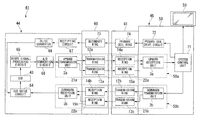
- FIG. 7 A block diagram indicating the configuration of the endoscope system.
- FIG. 8 A cross-sectional diagram of the endoscope system in a state where a living-body outside connection part and a scope-side connection part of the same are connected.
- FIGS. 1 to 5 A first embodiment of a signal transmission device according to the present invention will be explained with reference to FIGS. 1 to 5 .
- a signal transmission device 1 of this embodiment includes a transmission unit 2 that transmits transmission data (transmission signal), a reception unit 3 that receives the transmission data, and a static coupling unit 4 that divides the transmission unit 2 side and the reception unit 3 side in a DC (direct current) manner and transmits the signal.
- the transmission unit 2 includes a data generation circuit 7 that generates transmission data constituted by a multi-value signal described below, a multi-value encoder circuit 8 that modulates this transmission data to a signal having four types of strength level, and a strength-modulation driver circuit 11 that outputs the signal modulated by the multi-value encoder circuit 8 and the signal in a reverse phase to the encoded data to one end of each of transfer lines 9 a and 10 a.
- the static coupling unit 4 includes a transmission ring (first electrode) 12 and a transmission ring (third electrode) 13 , which are electrically connected to the strength-modulation driver circuit 11 by the transfer lines 9 a and 10 a respectively, and a reception ring (second electrode) 14 and a reception ring (fourth electrode) 15 that deliver signals by static coupling with the transmission rings 12 and 13 respectively.
- Encoded data output via the strength-modulation driver circuit 11 to one end of the transfer line 9 a is delivered via the transmission ring 12 provided at the end other of the transfer line 9 a to the reception ring 14 .
- encoded data output via the strength-modulation driver circuit 11 to one end of the transfer line 10 a is delivered via the transmission ring 13 provided at the end other of the transfer line 10 a to the reception ring 15 .
- the reception unit 3 includes a signal level detection circuit 16 that is electrically connected to the reception rings 14 and 15 and detects the type of strength level of each signal delivered to them, a multi-value decoder circuit 17 that demodulates encoded data from signals having four types of strength level, and a data processing circuit 18 that performs data processing to the demodulated transmission data.
- Encoded data delivered to the reception ring 14 is delivered to the signal level detection circuit 16 by a transfer line 9 b , one end of which connects to the reception ring 14 .
- reverse-phase data delivered to the reception ring 15 is delivered to the signal level detection circuit 16 by a transfer line 10 b , one end of which connects to the reception ring 15 .
- the signal level detection circuit 16 by taking the difference in strength levels of the delivered encoded data and the reverse-phase data, i.e. by using the differential signal, noise similarly contained in these two pieces of data can be removed.
- a multi-value decoder circuit 17 also functions as a clock reproduction circuit that reproduces a clock from the encoded data. The multi-value decoder circuit 17 then uses the reproduced clock to decode the transmission data from signals having four types of strength levels.
- the decoded data is delivered to the data processing circuit 18 and processed.
- the coupling unit 4 which includes the transmission-side connection unit 21 including the transmission ring 12 and the transmission ring 13 , and the reception-side connection unit 22 including the reception ring 14 and the reception ring 15 , will be explained.
- the transmission-side connection unit 21 is formed in a substantially circular-column shape, and the reception-side connection unit 22 is formed in a substantially cylindrical shape such as to surround the outer peripheral face of the transmission-side connection unit 21 .
- the transmission-side connection unit 21 is capable of being connected and disconnected to/from the reception-side connection unit 22 .
- each is disposed on a common axis C 1 concentrically.
- the transmission-side connection unit 21 includes a transmission-side axis member 25 that is tubular in shape and is disposed such that its own axis matches the axis C 1 , the transmission rings 12 and 13 that are cylindrical in shape and are disposed such that their own axes each match the axis C 1 , a transmission-side covering member 26 made from a dielectric provided such as to cover the top face including the outer peripheral faces of the transmission rings 12 and 13 , and a bearing 27 formed in a ring shape.
- the transmission rings 12 and 13 are disposed such as to extend along the axis C 1 , and are respectively attached to the transmission-side axis member 25 via supporting members 28 and 29 made from a material having insulating properties.
- the transfer lines 9 a and 10 a connected to the transmission ring 12 and the transmission ring 13 are inserted into through-holes provided in the supporting members 28 and 29 and connected to the strength-modulation driver circuit 11 .
- a shielding member 30 is provided between the transmission ring 12 and the transmission ring 13 to block any electromagnetic effect between them.
- the bearing 27 is formed such as to protrude slightly radially outward from the transmission-side covering member 26 , and is in an exposed state.
- the outer peripheral face and inner peripheral face of the bearing 27 are arranged along the axis C 1 .
- the outer peripheral face is configured to being capable of rotate around the axis C 1 with respect to the inner peripheral face in a state of reduced frictional force.
- the reception-side connection unit 22 includes a reception-side axis member 33 that is tubular in shape and is disposed such that its own axis matches the axis C 1 , the reception rings 14 and 15 that are cylindrical in shape and are disposed such that their own axes each match the axis C 1 , and a reception-side covering member 34 made from a dielectric provided so as to cover the top face including the inner peripheral faces and outer peripheral faces of the reception rings 14 and 15 .
- the reception rings 14 and 15 are disposed so as to extend along the axis C 1 , and supporting members 35 and 36 made from a material having insulating properties are respectively attached, on the outer peripheral faces of the reception rings 14 and 15 .
- the transfer lines 9 b and 10 b connected to the reception ring 14 and the reception ring 15 are inserted into through-holes provided in the supporting members 35 and 36 and connected to the signal level detection circuit 16 .
- a shielding member 37 is provided between the reception ring 14 and the reception ring 15 to block any electromagnetic effect between them.
- the transmission-side connection unit 21 is able to rotate around the axis C 1 with respect to the reception-side connection unit 22 ; in addition, the reception ring 14 is disposed opposite the transmission ring 12 , and the reception ring 15 is disposed opposite the transmission ring 13 .
- the transmission ring 12 is disposed to being capable of be statically coupled with the reception ring 14
- the transmission ring 13 is disposed to being capable of statically coupled with the reception ring 15 .
- the data generation circuit 7 of the transmission unit 2 shown in FIG. 1 generates transmission data, for example, ‘0, 1, 2, 3, 0, . . . ’ in decimal notation such as is shown in FIG. 3 .
- transmission data is expressed as a signal including two strength levels, namely an ‘H’ signal and an ‘L’ signal
- two signals including two strength levels are needed to express four types of signals ‘0’ to ‘3’ in decimal notation.
- the first and second signals of the two signals corresponding to ‘0’ to ‘3’ in decimal notation become the strength levels shown in decimal notation as shown in FIG. 3 .
- the multi-value encoder circuit 8 When the transmission data expressed by two signals is input to the multi-value encoder circuit 8 , as shown in Step S 1 of FIG. 4 , the multi-value encoder circuit 8 creates encoded data, in which each signal has four types of strength level, from the transmission data.
- FIG. 3 is an example of this encoded data.
- the data in each signal is expressed with four types of strength level from level 0 to level 3 .
- the four types of strength level are distinguished according to, for example, difference in the size of the voltage, with the differences between the strength levels (level 1 and level 0 , level 2 and level 1 , level 3 and level 2 ) being set such that they are mutually equal.
- the encoded data expresses one value by the amount of change in the strength levels of the two successive signals which are grouped into That is, the strength level of the first signal and the strength level of the second signal (the later signal) are mutually different.
- decimal notation For example, of two successive signals, when the first signal is level 3 and the second signal is level 0 , so that there is a difference of three strength levels between them, this is expressed in decimal notation as ‘0’. When the first signal is level 2 and the second signal is level 1 , so that there is a difference of one strength level between them, this is expressed in decimal notation as ‘1’, and so on.
- the transmission data is encoded such that the average value of the strength levels of the two successive signals is substantially constant (including constant), irrespective of the size of the transmission data expressed as ‘0’ to ‘3’ in decimal notation.
- the first signal is level 3 and the second signal is level 0 , so that the average value of the strength levels of the two signals becomes a value between level 2 and level 1 .
- the first signal is level 2 and the second signal is level 1 , so that here too the average value of the strength levels of the two signals becomes a value between level 2 and level 1 .
- the strength-modulation driver circuit 11 creates data in reverse phase to the encoded data. As shown in FIG. 3 , when the encoded data is level 3 , level 0 , level 2 , level 1 , . . . , the reverse-phase data becomes level 0 , level 3 , level 1 , level 2 , . . . .
- Step S 2 the encoded data and the reverse-phase data are delivered via the static coupling unit 4 to the reception unit 3 side.
- FIG. 3 shows an example of a differential signal (hereinafter abbreviated as ‘detected data’) based on the encoded data and the reverse-phase data received by the reception rings 14 and 15 and detected by the signal level detection circuit 16 . Since the strength level of the second signal of the two successive signals is different from the strength level of the first signal, as indicated by the solid line in FIG. 3 , attenuation of the strength level of the second signal is suppressed. In contrast, the first signal suffers attenuation due to the strength level of the signal (the second signal) before it, and there is a possibility that its strength level may be difficult to be detected.
- a graph of eye openings indicating the quality characteristics of the signals transmitted via the static coupling unit 4 becomes like, for example, the one shown in FIG. 5 . While an eye opens in correspondence with the second signal, no eye opens in correspondence with the first signal. This graph reveals that it is possible to reliably detect and determine the strength level of the second signal of two successive signals expressing one value.
- the second signal for ‘1’ and the first signal for ‘2’ will both be at level 1 .
- the detected data is input to the multi-value decoder circuit 17 , where a clock reproduction process is performed. As shown in Step S 3 , the multi-value decoder circuit 17 then uses this reproduced clock to perform a decoding process, with two successive signals of detected data as the unit of processing, so as to detect only the strength level of the second signal, whereby it identifies the one value and creates decoded data shown in FIG. 3 .
- Step S 4 the decoded data created by the multi-value decoder circuit 17 is delivered to the data processing circuit 18 , which performs a signal process to the decoded data.
- the transmission-side connection unit 21 engages with the reception-side connection unit 22 , the transmission ring 12 of the transmission-side connection unit 21 and the reception ring 14 of the reception-side connection unit 22 become statically coupled.
- the transmission unit 2 sends successive signals of different strength levels, one signal having four types of strength level, the signals being encoded so as to express a transmission signal using the amount of change in the strength level. Therefore, by making the strength levels of successive signals different, it is possible to suppress attenuation of the strength level of the signal delivered to the reception ring 14 due to static coupling.
- the transmission unit 2 encodes the data such that the average value of the strength levels of the successive signals is substantially constant, irrespective of the size of the transmission signal, even if the transmission signal is coded as a multi-value signal with four types of strength level, the DC level of the signal can be stabilized.
- the signal whose strength level is detected is the second of two successive signals, attenuation of the strength level due to successive signals with equal strength levels is suppressed, and the strength level of the signal can be reliably detected.
- the transmission ring 12 is statically coupled with the reception ring 14
- the transmission ring 13 is statically coupled with the reception ring 15 .
- the static coupling between the transmission ring 12 and the reception ring 14 delivers encoded data from the transmission unit 2 to the reception unit 3
- the static coupling between the transmission ring 13 and the reception ring 15 delivers reverse-phase data of the encoded data from the transmission unit 2 to the reception unit 3 .
- the transmission unit 2 includes the data generation circuit 7 .
- the configuration may be adopted that where the transmission unit 2 does not include the data generation circuit 7 , and the transmission data is input to the multi-value encoder circuit 8 from the outside.
- the reception unit 3 includes the data processing circuit 18 .
- the configuration can be one where the reception unit 3 does not include the data processing circuit 18 , and data decoded by the multi-value decoder circuit 17 is output to the outside.
- an endoscope system 41 is a device for inserting an insertion part 42 into a living body, and observing the inside of the living body.
- the endoscope system 41 of this embodiment includes an endoscopic scope 44 including an insertion part 42 that is inserted into a living body and is provided with a CCD (observation means) 43 capable of observing a distal-end side, a living body exterior device 45 provided outside the living body, and the signal transmission devices 50 a and 50 b described above, which are built into the endoscopic scope 44 and the living body exterior device 45 .
- CCD observation means
- the signal transmission devices 50 a and 50 b of this embodiment are not provided with the data generation circuit 7 and the data processing circuit 18 of the embodiment described above; instead, transmission data from the outside is input to the transmission unit, and the reception unit outputs decoded data to the outside.
- the endoscopic scope 44 includes the insertion part 42 mentioned above, which is made from a flexible material and includes a bend part 48 on its distal-end side, an operation part 49 attached to the proximal-end side of the insertion part 42 and including an angle knob or the like for controlling the bending of the bend part 48 , and a universal cord 50 for connecting the operation part 49 to the living body exterior device 45 .
- an illuminating means which are not illustrated such as a light-gathering optical system for illuminating the distal-end side with illuminating light that has been led along a living body outer-side light guide 84 and a scope-side light guide 79 described below, and the CCD 43 are provided.
- the living body exterior device 45 includes a main unit 58 as its base, and a display unit 59 that displays a video signal from the CCD 43 .
- a scope-side connection part 60 and a living body outer-side connection part 61 which is capable of connecting and is connecting to/from each other are provided between the proximal-end part of the universal cord 50 and the main unit 58 .
- data can be delivered from the endoscopic scope 44 to the living body exterior device 45 (upward) and from the living body exterior device 45 to the endoscopic scope 44 (downward).
- the universal cord 50 since the scope-side connection part 60 and the living body outer-side connection part 61 are provided between the proximal-end part of the universal cord 50 and the main unit 58 , the universal cord 50 constitutes the endoscopic scope 44 . However, when the scope-side connection part and the living body outer-side connection part are provided between the proximal-end part of the universal cord 50 and the operation part 49 , the universal cord constitutes the living body exterior device 45 .
- the endoscopic scope is the part on the insertion part 42 side of the section divided by the scope-side connection part and the living body outer-side connection part, while the living body exterior device is the part on the main unit 58 side.
- the endoscopic scope 44 includes a CCD driver circuit 64 that controls the drive status of the CCD 43 , a video signal processing circuit 65 that processes image data (video signals) and the like captured by the CCD 43 , an A/D conversion circuit 66 that converts an analog signal obtained by the video signal processing circuit 65 to a digital signal, a rectifying circuit 67 that converts alternating current to direct current, and a DC/DC converter 68 that adjusts the voltage of the direct current.
- a CCD driver circuit 64 that controls the drive status of the CCD 43
- a video signal processing circuit 65 that processes image data (video signals) and the like captured by the CCD 43
- an A/D conversion circuit 66 that converts an analog signal obtained by the video signal processing circuit 65 to a digital signal
- a rectifying circuit 67 that converts alternating current to direct current
- a DC/DC converter 68 that adjusts the voltage of the direct current.
- the endoscopic scope 44 further includes an upward transmission unit 2 a of the signal transmission device 50 a , and a downward reception unit 3 b of the signal transmission device 50 b.
- the main unit 58 includes a system control unit 71 that controls the endoscopic scope 44 and the living body exterior device 45 , and processes video signals, a primary coil driver circuit 72 that controls the drive status of a primary coil ring 74 described below, an upward reception unit 3 a of the signal transmission device 50 a , and a downward transmission unit 2 b of the signal transmission device 50 b.
- the scope-side connection part 60 includes a secondary coil ring 73 which electric power is supplied to, a transmission ring (first electrode) 12 a and a transmission ring (third electrode) 13 a of the signal transmission device 50 a , and a reception ring (second electrode) 14 b and a reception ring (fourth electrode) 15 b of the signal transmission device 50 b.
- the living body outer-side connection part 61 includes a primary coil ring 74 which supplies electric power, a reception ring (second electrode) 14 a and a reception ring (fourth electrode) 15 a of the signal transmission device 50 a , and a transmission ring (first electrode) 12 b and a transmission ring (third electrode) 13 b of the signal transmission device 50 b.
- the scope-side connection part 60 is formed in a substantially circular-column shape, and the living body outer-side connection part 61 is formed in a substantially cylindrical shape such as to surround the outer peripheral face of the scope-side connection part 60 .
- each is disposed on a common axis C 2 concentrically.
- the reception ring 15 b , the reception ring 14 b , the secondary coil ring 73 , the transmission ring 13 a , and the transmission ring 12 a are attached in that order via supporting members 28 29 35 36 etc made from material with insulating properties, on the same axis from the proximal-end part side of a tubular scope-side axis member 77 toward the center part side, to the proximal-end part of the scope-side axis member 77 .
- Shielding members 30 are provided between the reception ring 15 b and the reception ring 14 b, between the reception ring 14 b and the secondary ring 73 , between the secondary ring 73 and the transmission ring 13 a , and between the transmission ring 13 a and the transmission ring 12 a , to block any electromagnetic effects between them.
- the top face including the outer peripheral faces of the reception rings 15 b and 14 b , the secondary ring 73 , and the transmission rings 13 a and 12 a , is covered by a scope-side covering member 78 made from a dielectric.
- a scope-side light guide 79 is inserted into the scope-side axis member 77 , and leads illuminating light to an unillustrated illuminating means.
- the reception ring 14 a , the reception ring 15 a , the primary ring 74 , the transmission ring 12 b , and the transmission ring 13 b are provided in that order on the same axis leading towards the main unit 58 side.
- Shielding members 37 are provided between the reception ring 14 a and the reception ring 15 a , between the reception ring 15 a and the primary coil ring 74 , between the primary coil ring 74 and the transmission ring 12 b , and between the transmission ring 12 b and the transmission ring 13 b , to block any electromagnetic effects between them.
- the top face including the outer peripheral faces of the reception rings 14 a and 15 a , the primary coil ring 74 , and the transmission rings 12 b and 13 b , is covered by a living body outer-side covering member 82 made from a dielectric.
- a living body outer-side light guide 84 is inserted into a tubular living body outer-side axis member 83 , and leads illuminating light generated by an unillustrated illuminating means provided inside the main unit 58 .
- the scope-side connection part 60 is able to rotate around the axis C 2 with respect to the living body outer-side connection part 61 ; in addition, the transmission ring 12 a is disposed opposite the reception ring 14 a , the transmission ring 13 a is disposed opposite the transmission ring reception 15 a , the secondary ring 73 is disposed opposite the primary coil ring 74 , the reception ring 14 b is disposed opposite the transmission ring 12 b , and the reception ring 15 b is disposed opposite the reception ring transmission 13 b.
- the side face of the scope-side light guide 79 and the side face of the living body outer-side light guide 84 are also disposed opposite each other, enabling illuminating light to be delivered from the living body outer-side light guide 84 side to the scope-side light guide 79 .
- the scope-side connection part 60 is provided with a first connection part 21 a including a first electrode in the signal transmission device 50 a , and a second connection part 22 b including a second electrode in the signal transmission device 50 b .
- the living body outer-side connection part 61 is provided with a second connection part 22 a including a second electrode in the signal transmission device 50 a , and a first connection part 21 b including a first electrode in the signal transmission device 50 b.
- the system control unit 71 is connected to each of the downward transmission unit 2 b , the upward reception unit 3 a , the primary coil driver circuit 72 , and the display unit 59 .
- the downward transmission unit 2 b encodes the control signal, and creates encoded data and data in a reverse phase of the encoded data. These pieces of data are delivered by static coupling between the transmission ring 12 b and the reception ring 14 b , and between the transmission ring 13 b and the reception ring 15 b , and are decoded in the downward reception unit 3 b.
- the decoded control signal is delivered to the CCD driver circuit 64 connected to the downward reception unit 3 b . Based on this control signal, the CCD driver circuit 64 controls the CCD 43 that itself is connected to.
- a predetermined AC current is supplied to the primary coil ring 74 connected to the primary coil driver circuit 72 . Due to mutual induction between the primary coil ring 74 and the secondary ring 73 , the AC current flows to the secondary ring 73 .
- This AC current is sent to the rectifying circuit 67 connected to the secondary ring 73 , where it is converted to DC current.
- the voltage of the converted DC current is adjusted by the DC/DC converter 68 connected to the rectifying circuit 67 , and the DC current is then supplied to the CCD driver circuit 64 and the like.
- a video signal captured by the CCD 43 is delivered to the video signal processing circuit 65 connected to the CCD 43 , where it is processed to create an analog signal.
- This analog signal is converted to a digital signal by the A/D conversion circuit 66 connected to the video signal processing circuit 65 .
- the converted digital signal is then delivered to the upward transmission unit 2 a connected to the A/D conversion circuit 66 .
- the video signal delivered to the upward transmission unit 2 a is encoded, and encoded data and data in a reverse phase to this encoded data are created. These pieces of data are delivered by static coupling between the transmission ring 12 a and the reception ring 14 a , and between the transmission ring 13 a and the reception ring 15 a , and are decoded by the upward reception unit 3 a.
- the decoded video signal is delivered from the upward reception unit 3 a to the system control unit 71 , where it is processed before being sent to the display unit 59 , where it is displayed.
- the endoscopic scope 44 is provided with the upward transmission unit 2 a of the signal transmission device 50 a , and the downward reception unit 3 b of the signal transmission device 50 b
- the living body exterior device 45 is provided with the upward reception unit 3 a of the signal transmission device 50 a
- the downward transmission unit 2 b of the signal transmission device 50 b By connecting the scope-side connection part 60 to the living body outer-side connection part 61 , the transmission ring 12 a and the reception ring 14 a , and the reception ring 14 b and the transmission ring 12 b , are respectively disposed opposite each other and are statically coupled.
- a signal with a stabilized DC level can be sent from the upward transmission unit 2 a to the upward reception unit 3 a , and from the downward transmission unit 2 b to the downward reception unit 3 b.
- the scope-side covering member 78 by covering the surface of the reception rings 15 b , 14 b , the secondary coil ring 73 , the transmission rings 13 a and 12 a with the scope-side covering member 78 , it is possible to suppress corrosion of the internal components such as the electrodes during cleaning.
- the signal transmission device is used in delivering transmission data in both directions between the endoscopic scope 44 and the living body exterior device 45 .
- the signal transmission device can acceptably be used in, for example, delivering data only from the endoscopic scope 44 to the living body exterior device 45 .
- the endoscopic scope 44 can be provided with a battery or the like, and this battery can supply power to the CCD driver circuit 64 etc.
- the multi-value encoder circuit 8 modulated the transmission data to a signal where every signal has four types of strength level.
- the number of types of strength levels of each signal need only be three or more. Four types, eight types, or sixteen types of strength level are preferable.
- a transmission ring as one electrode and a transmission ring as a second electrode were disposed such that they extend along the axis.
- the first electrode and the second electrode can be formed into plates, and disposed such that they intersect the axis.
- the configuration can be one where, when there is low attenuation in the strength level of the signal, the reception unit identifies the one value with the strength level of the first of two successive signals.
- the configuration can be one where three or more successive signals express one value. In this case, two adjacent signals need only have different strength levels.
Abstract
Description
Claims (4)
Applications Claiming Priority (3)
| Application Number | Priority Date | Filing Date | Title |
|---|---|---|---|
| JP2009178247A JP5379596B2 (en) | 2009-07-30 | 2009-07-30 | Signal transmission device and endoscope system |
| JP2009-178247 | 2009-07-30 | ||
| PCT/JP2010/062449 WO2011013591A1 (en) | 2009-07-30 | 2010-07-23 | Signal transmitting device and endoscopic system |
Related Parent Applications (1)
| Application Number | Title | Priority Date | Filing Date |
|---|---|---|---|
| PCT/JP2010/062449 Continuation WO2011013591A1 (en) | 2009-07-30 | 2010-07-23 | Signal transmitting device and endoscopic system |
Publications (2)
| Publication Number | Publication Date |
|---|---|
| US20120197085A1 US20120197085A1 (en) | 2012-08-02 |
| US8939893B2 true US8939893B2 (en) | 2015-01-27 |
Family
ID=43529248
Family Applications (1)
| Application Number | Title | Priority Date | Filing Date |
|---|---|---|---|
| US13/361,661 Active 2031-06-16 US8939893B2 (en) | 2009-07-30 | 2012-01-30 | Signal transmission device and endoscope system |
Country Status (5)
| Country | Link |
|---|---|
| US (1) | US8939893B2 (en) |
| EP (1) | EP2460459B1 (en) |
| JP (1) | JP5379596B2 (en) |
| CN (1) | CN102469926B (en) |
| WO (1) | WO2011013591A1 (en) |
Families Citing this family (6)
| Publication number | Priority date | Publication date | Assignee | Title |
|---|---|---|---|---|
| US9525852B2 (en) * | 2013-08-02 | 2016-12-20 | General Electric Company | Systems and methods for embedded imaging clocking |
| JP2015210193A (en) * | 2014-04-25 | 2015-11-24 | 株式会社ジェイテクト | Torque detection system and electrically-driven power steering device having the same |
| EP3507921B1 (en) * | 2016-09-02 | 2021-07-14 | Koninklijke Philips N.V. | Optical transceiver, optical system, interventional device and method for supplying energy and returning data |
| JP6315875B1 (en) * | 2016-12-15 | 2018-04-25 | オリンパス株式会社 | Endoscope and endoscope system |
| CN109310304B (en) * | 2016-12-15 | 2021-08-17 | 奥林巴斯株式会社 | Endoscope and endoscope system |
| US11221660B2 (en) * | 2019-01-31 | 2022-01-11 | Hewlett Packard Enterprise Development Lp | Fault detection based on comparing input current and moving average input current |
Citations (12)
| Publication number | Priority date | Publication date | Assignee | Title |
|---|---|---|---|---|
| JPH10308728A (en) | 1997-05-08 | 1998-11-17 | Kokusai Electric Co Ltd | Synchronous transmission system |
| US20030091118A1 (en) | 2000-04-18 | 2003-05-15 | Georg Lohr | Array for the transmission of electrical energy or signals |
| JP2004147052A (en) | 2002-10-24 | 2004-05-20 | Mitsubishi Electric Corp | Digital modulation device |
| WO2005077250A1 (en) | 2004-02-16 | 2005-08-25 | Olympus Corporation | Endoscope system |
| WO2005077249A1 (en) | 2004-02-16 | 2005-08-25 | Olympus Corporation | Endoscope system |
| US20050280509A1 (en) | 2004-06-17 | 2005-12-22 | Fujitsu Limited | Reader device, its transmission method, and tag |
| JP2006287052A (en) | 2005-04-01 | 2006-10-19 | Canon Inc | Capacitance electric-coupling device |
| US20070078304A1 (en) | 2005-10-03 | 2007-04-05 | Olympus Corporation | Electronic endoscope system |
| JP2008224936A (en) | 2007-03-12 | 2008-09-25 | Toyo Univ | Display device |
| US20090058997A1 (en) | 2007-09-05 | 2009-03-05 | Olympus Corporation | Endoscope system and signal transmitting method |
| JP2009056240A (en) | 2007-09-03 | 2009-03-19 | Olympus Corp | Endoscope system |
| WO2009035028A1 (en) | 2007-09-12 | 2009-03-19 | Nec Corporation | Data transmission device and data transmission method |
Family Cites Families (2)
| Publication number | Priority date | Publication date | Assignee | Title |
|---|---|---|---|---|
| WO2001080443A1 (en) * | 2000-04-18 | 2001-10-25 | Schleifring Und Apparatebau Gmbh | Arrangement for contactless transmission of electric signals or energy between several mobile units |
| JP5223357B2 (en) | 2008-01-29 | 2013-06-26 | 日産自動車株式会社 | Vehicle seat heating device |
-
2009
- 2009-07-30 JP JP2009178247A patent/JP5379596B2/en not_active Expired - Fee Related
-
2010
- 2010-07-23 EP EP10804337.3A patent/EP2460459B1/en not_active Not-in-force
- 2010-07-23 CN CN201080031404.7A patent/CN102469926B/en not_active Expired - Fee Related
- 2010-07-23 WO PCT/JP2010/062449 patent/WO2011013591A1/en active Application Filing
-
2012
- 2012-01-30 US US13/361,661 patent/US8939893B2/en active Active
Patent Citations (18)
| Publication number | Priority date | Publication date | Assignee | Title |
|---|---|---|---|---|
| JPH10308728A (en) | 1997-05-08 | 1998-11-17 | Kokusai Electric Co Ltd | Synchronous transmission system |
| US20030091118A1 (en) | 2000-04-18 | 2003-05-15 | Georg Lohr | Array for the transmission of electrical energy or signals |
| JP2004511191A (en) | 2000-04-18 | 2004-04-08 | シュライフリング ウント アパラーテバウ ゲゼルシャフト ミット ベシュレンクテル ハフツング | Devices for transmitting electrical energy or signals |
| JP2004147052A (en) | 2002-10-24 | 2004-05-20 | Mitsubishi Electric Corp | Digital modulation device |
| US20060116552A1 (en) | 2004-02-16 | 2006-06-01 | Olympus Corporation | Endoscope system |
| WO2005077249A1 (en) | 2004-02-16 | 2005-08-25 | Olympus Corporation | Endoscope system |
| WO2005077250A1 (en) | 2004-02-16 | 2005-08-25 | Olympus Corporation | Endoscope system |
| US20060116550A1 (en) | 2004-02-16 | 2006-06-01 | Olympus Corporation | Endoscope system |
| US20050280509A1 (en) | 2004-06-17 | 2005-12-22 | Fujitsu Limited | Reader device, its transmission method, and tag |
| JP2006005651A (en) | 2004-06-17 | 2006-01-05 | Fujitsu Ltd | Reader device, and transmitting method and tag of the same |
| JP2006287052A (en) | 2005-04-01 | 2006-10-19 | Canon Inc | Capacitance electric-coupling device |
| US20070078304A1 (en) | 2005-10-03 | 2007-04-05 | Olympus Corporation | Electronic endoscope system |
| JP2007097767A (en) | 2005-10-03 | 2007-04-19 | Olympus Corp | Electron endoscope system |
| JP2008224936A (en) | 2007-03-12 | 2008-09-25 | Toyo Univ | Display device |
| JP2009056240A (en) | 2007-09-03 | 2009-03-19 | Olympus Corp | Endoscope system |
| US20090058997A1 (en) | 2007-09-05 | 2009-03-05 | Olympus Corporation | Endoscope system and signal transmitting method |
| JP2009061032A (en) | 2007-09-05 | 2009-03-26 | Olympus Corp | Endoscope system |
| WO2009035028A1 (en) | 2007-09-12 | 2009-03-19 | Nec Corporation | Data transmission device and data transmission method |
Non-Patent Citations (2)
| Title |
|---|
| International Search Report of PCT/JP2010/062449, mailing date of Aug. 24, 2010. |
| Japanese Notice of Allowance dated Sep. 3, 2013, issued in corresponding Japanese Patent Application No. 2009-178247 with English translation (6 pages). |
Also Published As
| Publication number | Publication date |
|---|---|
| EP2460459A4 (en) | 2012-12-26 |
| EP2460459A1 (en) | 2012-06-06 |
| EP2460459B1 (en) | 2014-01-01 |
| JP2011030667A (en) | 2011-02-17 |
| JP5379596B2 (en) | 2013-12-25 |
| CN102469926A (en) | 2012-05-23 |
| US20120197085A1 (en) | 2012-08-02 |
| CN102469926B (en) | 2015-01-14 |
| WO2011013591A1 (en) | 2011-02-03 |
Similar Documents
| Publication | Publication Date | Title |
|---|---|---|
| US8939893B2 (en) | Signal transmission device and endoscope system | |
| US9089255B2 (en) | Endoscope system | |
| US7914443B2 (en) | Endoscope with non-contact signal transmission and reception | |
| US8449453B2 (en) | Endoscopic image processing apparatus and endoscope system | |
| JP5356632B1 (en) | Imaging system | |
| US9763560B2 (en) | Endoscope system and electrostatic coupling | |
| JP2007097767A (en) | Electron endoscope system | |
| JP4757019B2 (en) | Endoscope device | |
| JP3748979B2 (en) | Electronic endoscope device | |
| CN110367910A (en) | Endoscopy joints, endoscope mirror body, cold light source for endoscope and endoscopic system | |
| CN104039213B (en) | Image unit and camera system | |
| US10133013B2 (en) | Apparatus and method of providing an interface to an electrically powered instrument | |
| JP2012245107A (en) | Endoscope system | |
| JP5307518B2 (en) | Medical equipment system | |
| CN103648359A (en) | Endoscope | |
| WO2016080527A1 (en) | Endoscopic system and endoscope | |
| CN109310304B (en) | Endoscope and endoscope system | |
| CN104545773A (en) | CCD electronic imaging device and endoscope thereof | |
| JP2019150466A (en) | Medical equipment | |
| JP2011083388A (en) | Electronic endoscope system and processor for electronic endoscope | |
| JP2005198844A (en) | Connector device for endoscope |
Legal Events
| Date | Code | Title | Description |
|---|---|---|---|
| AS | Assignment |
Owner name: OLYMPUS CORPORATION, JAPAN Free format text: ASSIGNMENT OF ASSIGNORS INTEREST;ASSIGNORS:KATO, SHUICHI;KAWATA, SUSUMU;HONDA, MAKOTO;SIGNING DATES FROM 20120309 TO 20120322;REEL/FRAME:028013/0588 Owner name: OLYMPUS MEDICAL SYSTEMS CORP., JAPAN Free format text: ASSIGNMENT OF ASSIGNORS INTEREST;ASSIGNORS:KATO, SHUICHI;KAWATA, SUSUMU;HONDA, MAKOTO;SIGNING DATES FROM 20120309 TO 20120322;REEL/FRAME:028013/0588 |
|
| STCF | Information on status: patent grant |
Free format text: PATENTED CASE |
|
| AS | Assignment |
Owner name: OLYMPUS CORPORATION, JAPAN Free format text: ASSIGNMENT OF ASSIGNORS INTEREST;ASSIGNOR:OLYMPUS MEDICAL SYSTEMS CORP.;REEL/FRAME:036276/0543 Effective date: 20150401 |
|
| AS | Assignment |
Owner name: OLYMPUS CORPORATION, JAPAN Free format text: CHANGE OF ADDRESS;ASSIGNOR:OLYMPUS CORPORATION;REEL/FRAME:039344/0502 Effective date: 20160401 |
|
| MAFP | Maintenance fee payment |
Free format text: PAYMENT OF MAINTENANCE FEE, 4TH YEAR, LARGE ENTITY (ORIGINAL EVENT CODE: M1551) Year of fee payment: 4 |
|
| MAFP | Maintenance fee payment |
Free format text: PAYMENT OF MAINTENANCE FEE, 8TH YEAR, LARGE ENTITY (ORIGINAL EVENT CODE: M1552); ENTITY STATUS OF PATENT OWNER: LARGE ENTITY Year of fee payment: 8 |