US8881744B2 - Lash holder - Google Patents
Lash holder Download PDFInfo
- Publication number
- US8881744B2 US8881744B2 US13/660,657 US201213660657A US8881744B2 US 8881744 B2 US8881744 B2 US 8881744B2 US 201213660657 A US201213660657 A US 201213660657A US 8881744 B2 US8881744 B2 US 8881744B2
- Authority
- US
- United States
- Prior art keywords
- strip
- lashes
- top part
- pedestal
- lash
- Prior art date
- Legal status (The legal status is an assumption and is not a legal conclusion. Google has not performed a legal analysis and makes no representation as to the accuracy of the status listed.)
- Expired - Fee Related
Links
- NJPPVKZQTLUDBO-UHFFFAOYSA-N novaluron Chemical compound C1=C(Cl)C(OC(F)(F)C(OC(F)(F)F)F)=CC=C1NC(=O)NC(=O)C1=C(F)C=CC=C1F NJPPVKZQTLUDBO-UHFFFAOYSA-N 0.000 claims description 38
- 230000002708 enhancing effect Effects 0.000 claims 2
- 230000037431 insertion Effects 0.000 claims 2
- 238000003780 insertion Methods 0.000 claims 2
- 210000000720 eyelash Anatomy 0.000 description 14
- 238000000034 method Methods 0.000 description 7
- 210000000707 wrist Anatomy 0.000 description 3
- 230000000712 assembly Effects 0.000 description 1
- 238000000429 assembly Methods 0.000 description 1
- 238000007796 conventional method Methods 0.000 description 1
- 230000003247 decreasing effect Effects 0.000 description 1
- 210000000744 eyelid Anatomy 0.000 description 1
- 210000004247 hand Anatomy 0.000 description 1
- 238000012986 modification Methods 0.000 description 1
- 230000004048 modification Effects 0.000 description 1
- 239000002699 waste material Substances 0.000 description 1
Images


Classifications
-
- A—HUMAN NECESSITIES
- A45—HAND OR TRAVELLING ARTICLES
- A45D—HAIRDRESSING OR SHAVING EQUIPMENT; EQUIPMENT FOR COSMETICS OR COSMETIC TREATMENTS, e.g. FOR MANICURING OR PEDICURING
- A45D44/00—Other cosmetic or toiletry articles, e.g. for hairdressers' rooms
-
- A—HUMAN NECESSITIES
- A41—WEARING APPAREL
- A41G—ARTIFICIAL FLOWERS; WIGS; MASKS; FEATHERS
- A41G5/00—Hair pieces, inserts, rolls, pads, or the like; Toupées
- A41G5/02—Artificial eyelashes; Artificial eyebrows
Definitions
- the present invention relates to a lash holder, particularly to a lash holder, which increases and enlarges the space between individual synthetic eyelashes, so that the user can take off the individual lashes easily.
- Eyelashes are a main focal point when it comes to your eyes, which is often enhanced by lengthening or curling the eyelashes to get a more beautiful look of the face.
- On the commercial market there are one piece strip lash extensions, which can be adhered to human eyelids after a length adjustment on the human lashes are made.
- the uniform styles of the one piece strip lash extensions cannot really fulfill or satisfy individual preferences.
- One piece strip lash extensions just do not look as natural as natural lashes do.
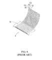
- an eyelash assembly 5 comprises: a strip 51 , wherein a bottom part of the strip is attached to a holder, and numerous lashes 52 are separated at the top part of the strip. Individual synthetic lashes are first taken off and then applied onto the human individual lash. A user can take off varying lengths of lashes for matching the customer's personal preferences.
- the main object of the present invention is to provide a lash holder, wherein the space between the lashes at the top is increased, enlarged and separated, so that it is easier for a user to take off the individual synthetic lashes one at a time.
- the lash holder of the present invention has a U-shaped sheet comprising of a curved top part and a bottom part fixed at a designated place; at least one strip with numerous synthetic lashes is set on the top part, so that the space between the individual lashes is increased, enlarged and separated so a user can take off individual lashes much easier than ever before.
- Another object of the present invention is to provide a lash holder, which is fixed at a designated place, so that a user can easily take off lashes and increase efficiency of the procedure.
- the lash holder of the present invention comprises: a rod at the bottom part combining a fixed component comprising a C-shaped sleeve for encompassing a human hand therein and a• connecting pedestal at the top of the C-shaped sleeve; the bottom end of the rod is plugged in the connecting pedestal; the lash holder is fixed on the hand by the fixed component, so that it is easy for users to take off lashes.
- FIG. 1 is a perspective view of the lash holder of the present invention.
- FIG. 2 is a partial perspective view of lashes strip set on the present invention.
- FIG. 3 is a perspective view of the lash holder of the present invention with a lashes strip set thereon, encompassing a human finger.
- FIG. 4 is an exploded view of the second embodiment of the present invention, showing the fixed component.
- FIG. 5 is a perspective view of the second embodiment of the present invention, showing rotation of the rod.
- FIG. 6 is a perspective view of the third embodiment of the present invention, showing a variant of the fixed component.
- FIG. 7 is a perspective view of the fourth embodiment of the present invention, showing three variant strips of lashes set on the lash holder.
- FIG. 8 is a partial perspective view of a conventional lash strip.
- the lash holder 3 of the present invention having a U-shaped sheet comprised of a curved top part 31 and a bottom part 32 fixed on a destined place; wherein an eyelash assembly 5 that includes a strip 51 connected to numerous lashes 52 is set thereon. Due to the curved top part 31 the space between individual lashes 52 are increased, enlarged and separated automatically, so the user can take off individual lashes 52 very easy.
- the eyelash assembly 5 used in the present invention is a conventional product.
- the eyelash assembly 5 comprises: a strip 51 , whose bottom part is adhered to the top part 31 of the lash holder 3 ; and numerous lashes 52 are at the top of the strip 51 . So the user can take off individual lashes 52 of the eyelash assembly 5 to adhere onto human lashes.
- FIG. 2 is a partial perspective view of the lashes strip set on the lash holder.
- the lash holder 3 is fixed on part of human hand (like finger, wrist or any other part) or any parts from where it is easy to take off the lashes 52 that are connected to the strip.
- the lash holder is open at the bottom for encompassing a part of a hand, like fingers. So a user can take off the lashes 52 more easily.
- the lash holder 3 is fixed on a part of the hand (like fingers, wrist or any other part) or any part from where it is easy to take off the strip 51 , by a fixed component.
- the lash holder 3 comprises a rod 33 at the bottom, combined further with a fixed component 4 comprising a C-shaped sleeve 41 for encompassing part of the human hand therein, like finger, and a connecting pedestal 42 set at the top part of the C-shaped sleeve 41 ; the bottom end of the rod 33 is plugged in the connecting pedestal 42 .
- the lash holder 3 is fixed on a human finger by the fixed component 4 , so that user can take off the lashes easily.
- the connecting pedestal 42 comprises: a bottom component 421 set on the top of the C-shaped sleeve 41 , and a sidewall 422 circling around the edge of the said bottom component 421 and building together with this bottom component a reservoir 423 ; the bottom end of the said rod 33 is for plugging in the said reservoir 423 of the connecting pedestal 42 .
- the rod 33 can have a groove/notch at the bottom for connecting the connecting pedestal 42 , having a rod-shape for plugging in the groove at the top (not shown).
- the rod 33 has a round section and is running fit with the reservoir 423 of the connecting pedestal 42 .
- the rod is rotatable, so the lash holder 3 as well as lashes strip 51 are also rotatable, thence the user can easily take off lashes 52 that are connected to the strip 5 from different angles.
- FIG. 6 shows the third embodiment of the present invention, the C-shaped sleeve 41 a is intended for encompassing the wrist therein.
- FIG. 7 shows eyelash assemblies 5 a , 5 b , and 5 c having strips 51 a , 51 b , and 51 c that are connected to lashes 52 a , 52 b , and 52 c , respectively, in decreased lengths adhered to the present invention.
- the top part 31 of the lash holder 3 is intended for engraving marks, like trade mark, customers name, website or other markings.
- the top part 31 of the lash holder 3 has several different marks 34 a , 34 b , 34 c , like S, M, L, so overlapping of lashes is avoided, when various lengths of lashes strips are adhered to.
- the identification marks are adhered to the paper strips on the lash holder 3 ; it is also feasible, if notches or projections are set on the lash holder 3 as marks.
Landscapes
- Engineering & Computer Science (AREA)
- Textile Engineering (AREA)
- Table Equipment (AREA)
Abstract
Description
Claims (14)
Priority Applications (1)
| Application Number | Priority Date | Filing Date | Title |
|---|---|---|---|
| US13/660,657 US8881744B2 (en) | 2012-10-25 | 2012-10-25 | Lash holder |
Applications Claiming Priority (1)
| Application Number | Priority Date | Filing Date | Title |
|---|---|---|---|
| US13/660,657 US8881744B2 (en) | 2012-10-25 | 2012-10-25 | Lash holder |
Publications (2)
| Publication Number | Publication Date |
|---|---|
| US20140116459A1 US20140116459A1 (en) | 2014-05-01 |
| US8881744B2 true US8881744B2 (en) | 2014-11-11 |
Family
ID=50545820
Family Applications (1)
| Application Number | Title | Priority Date | Filing Date |
|---|---|---|---|
| US13/660,657 Expired - Fee Related US8881744B2 (en) | 2012-10-25 | 2012-10-25 | Lash holder |
Country Status (1)
| Country | Link |
|---|---|
| US (1) | US8881744B2 (en) |
Cited By (22)
| Publication number | Priority date | Publication date | Assignee | Title |
|---|---|---|---|---|
| US20140191099A1 (en) * | 2013-01-09 | 2014-07-10 | Michael Anthony Schwarz | Mobile Holder |
| CN104106862A (en) * | 2014-08-12 | 2014-10-22 | 青岛发之美工艺品有限公司 | Three-dimensional column-type eyelash disperser capable of rotating for 360 degrees |
| US20160058088A1 (en) * | 2012-09-10 | 2016-03-03 | Jessica Le | Method for Securing Extension Lashes during an Eyelash Extension Procedure |
| WO2016118957A1 (en) * | 2015-01-23 | 2016-07-28 | Bella Lash Extensions, Llc | Tray for holding eyelash extensions and processes for applying eyelash extensions |
| US9585455B2 (en) * | 2015-04-10 | 2017-03-07 | Station 22, LLC | Nail polish container holder |
| US9961983B2 (en) | 2015-06-03 | 2018-05-08 | Lindsay Carey | Device for supporting eyelash extensions |
| US20180352886A1 (en) * | 2017-06-08 | 2018-12-13 | Sandi Schroeder | Eyelash Application System |
| USD865282S1 (en) * | 2018-04-18 | 2019-10-29 | Kiss Nail Products, Inc. | Eyelash vanity |
| USD870376S1 (en) * | 2017-12-15 | 2019-12-17 | Mitsubishi Pencil Company, Limited | Stopper for cosmetic applicator |
| USD925349S1 (en) * | 2019-01-15 | 2021-07-20 | Xtreme Lashes, Llc | Eyelash extension package |
| US11172749B2 (en) | 2016-12-20 | 2021-11-16 | Lashify, Inc. | Applicators and cases for artificial lash extensions |
| US11219260B2 (en) | 2016-07-28 | 2022-01-11 | Lashify, Inc. | Artificial lash extensions |
| USD952258S1 (en) | 2017-07-27 | 2022-05-17 | Lashify, Inc. | Artificial eyelash extension applicator |
| USD955645S1 (en) | 2016-12-05 | 2022-06-21 | Lashify, Inc. | Case for artificial lash extensions |
| US11432608B2 (en) | 2019-10-03 | 2022-09-06 | Lashify, Inc. | Stacking artificial lash extensions |
| USD981049S1 (en) | 2016-12-05 | 2023-03-14 | Lashify, Inc. | Case for artificial lash extensions |
| US11647802B2 (en) | 2018-10-19 | 2023-05-16 | Lashify, Inc. | Cases for storing lash extensions and methods for use and manufacture thereof |
| US11654049B2 (en) | 2020-03-24 | 2023-05-23 | Del, Llc | Instrument for isolating candidate eyelashes to attach prostheses |
| RU2799921C1 (en) * | 2022-05-27 | 2023-07-14 | Юлия Александровна Макарова | Eyelash extension method |
| USD999995S1 (en) | 2016-12-05 | 2023-09-26 | Lashify, Inc. | Artificial eyelash extension storage cartridge |
| US11832669B2 (en) | 2019-01-14 | 2023-12-05 | Lashify, Inc. | Lash extensions and methods of manufacture and use thereof |
| USD1023472S1 (en) * | 2023-12-14 | 2024-04-16 | Yunyun Lian | False eyelashes tray |
Families Citing this family (7)
| Publication number | Priority date | Publication date | Assignee | Title |
|---|---|---|---|---|
| KR101501111B1 (en) * | 2014-10-13 | 2015-03-12 | 박경신 | Artificial eyelashes |
| WO2016061337A1 (en) * | 2014-10-15 | 2016-04-21 | Lash Wrap LLC | Esthetic apparatus and related methods of use |
| KR101768602B1 (en) | 2015-10-15 | 2017-08-30 | 이자민 | Separation device of imitation eyelashes for eyelashes treatment |
| KR200484488Y1 (en) * | 2016-03-09 | 2017-09-11 | 주식회사 에이지 | A treatment equipment for eyelash extension |
| US10806194B1 (en) * | 2020-01-31 | 2020-10-20 | Joshua Tyson | Beauty gloves |
| US11884448B2 (en) | 2020-08-31 | 2024-01-30 | Kiss Nail Products, Inc. | Specialized tray device for eyelash extensions |
| JP1708496S (en) * | 2021-04-13 | 2022-02-28 | False eyelash holder |
Citations (10)
| Publication number | Priority date | Publication date | Assignee | Title |
|---|---|---|---|---|
| US615336A (en) * | 1898-12-06 | Separable fastener | ||
| US2176052A (en) * | 1938-03-21 | 1939-10-17 | Fred H Beyer | Wrist-carried implement holder |
| US3200823A (en) * | 1963-12-23 | 1965-08-17 | Sebastian Ray | Shaping device for artificial eyelashes |
| US3327391A (en) * | 1964-07-20 | 1967-06-27 | Richard D Malm | Dental material holding apparatus |
| US5052417A (en) * | 1989-04-10 | 1991-10-01 | Orlando Cordova | Eye shadow collector |
| US5732862A (en) * | 1997-02-14 | 1998-03-31 | Bull; Charles L. | Material holding apparatus with integrated finger mount |
| US6397633B1 (en) * | 1999-09-04 | 2002-06-04 | Hong Yi Cosmetics Co., Ltd. | Decorative cosmetic case |
| US7222629B1 (en) * | 2004-05-25 | 2007-05-29 | Yongho Han | Apparatus for securing an eyelash holder platform to a back of a beautician's hand |
| USD669223S1 (en) * | 2011-10-13 | 2012-10-16 | Kiss Nail Products, Inc. | Artificial eyelash tray |
| US20130133681A1 (en) * | 2011-11-28 | 2013-05-30 | Zachary Chipman | Eyelash Extension Trays |
-
2012
- 2012-10-25 US US13/660,657 patent/US8881744B2/en not_active Expired - Fee Related
Patent Citations (11)
| Publication number | Priority date | Publication date | Assignee | Title |
|---|---|---|---|---|
| US615336A (en) * | 1898-12-06 | Separable fastener | ||
| US2176052A (en) * | 1938-03-21 | 1939-10-17 | Fred H Beyer | Wrist-carried implement holder |
| US3200823A (en) * | 1963-12-23 | 1965-08-17 | Sebastian Ray | Shaping device for artificial eyelashes |
| US3327391A (en) * | 1964-07-20 | 1967-06-27 | Richard D Malm | Dental material holding apparatus |
| US5052417A (en) * | 1989-04-10 | 1991-10-01 | Orlando Cordova | Eye shadow collector |
| US5732862A (en) * | 1997-02-14 | 1998-03-31 | Bull; Charles L. | Material holding apparatus with integrated finger mount |
| US6397633B1 (en) * | 1999-09-04 | 2002-06-04 | Hong Yi Cosmetics Co., Ltd. | Decorative cosmetic case |
| US7222629B1 (en) * | 2004-05-25 | 2007-05-29 | Yongho Han | Apparatus for securing an eyelash holder platform to a back of a beautician's hand |
| USD669223S1 (en) * | 2011-10-13 | 2012-10-16 | Kiss Nail Products, Inc. | Artificial eyelash tray |
| US20130133681A1 (en) * | 2011-11-28 | 2013-05-30 | Zachary Chipman | Eyelash Extension Trays |
| US8701685B2 (en) * | 2011-11-28 | 2014-04-22 | Zachary Chipman | Eyelash extension trays |
Cited By (37)
| Publication number | Priority date | Publication date | Assignee | Title |
|---|---|---|---|---|
| US20160058088A1 (en) * | 2012-09-10 | 2016-03-03 | Jessica Le | Method for Securing Extension Lashes during an Eyelash Extension Procedure |
| US9930920B2 (en) * | 2012-09-10 | 2018-04-03 | Jessica Le | Method for securing extension lashes during an eyelash extension procedure |
| US20140191099A1 (en) * | 2013-01-09 | 2014-07-10 | Michael Anthony Schwarz | Mobile Holder |
| CN104106862A (en) * | 2014-08-12 | 2014-10-22 | 青岛发之美工艺品有限公司 | Three-dimensional column-type eyelash disperser capable of rotating for 360 degrees |
| CN104106862B (en) * | 2014-08-12 | 2015-11-18 | 青岛发之美工艺品有限公司 | Three-dimensional column type 360 degree rotates eyelashes disperser |
| WO2016118957A1 (en) * | 2015-01-23 | 2016-07-28 | Bella Lash Extensions, Llc | Tray for holding eyelash extensions and processes for applying eyelash extensions |
| US9585455B2 (en) * | 2015-04-10 | 2017-03-07 | Station 22, LLC | Nail polish container holder |
| USD821033S1 (en) | 2015-04-10 | 2018-06-19 | Station 22, LLC | Nail polish container holder |
| US9961983B2 (en) | 2015-06-03 | 2018-05-08 | Lindsay Carey | Device for supporting eyelash extensions |
| US11234472B2 (en) | 2016-07-28 | 2022-02-01 | Lashify, Inc. | Artificial lash extensions |
| US11219260B2 (en) | 2016-07-28 | 2022-01-11 | Lashify, Inc. | Artificial lash extensions |
| US11253020B2 (en) | 2016-07-28 | 2022-02-22 | Lashify, Inc. | Artificial lash extensions |
| US11330855B2 (en) | 2016-07-28 | 2022-05-17 | Lashify, Inc. | Method of applying artificial lash extensions |
| US11330856B2 (en) | 2016-07-28 | 2022-05-17 | Lashify, Inc. | Artificial lash extensions |
| USD999995S1 (en) | 2016-12-05 | 2023-09-26 | Lashify, Inc. | Artificial eyelash extension storage cartridge |
| USD981049S1 (en) | 2016-12-05 | 2023-03-14 | Lashify, Inc. | Case for artificial lash extensions |
| USD955645S1 (en) | 2016-12-05 | 2022-06-21 | Lashify, Inc. | Case for artificial lash extensions |
| US11832710B2 (en) | 2016-12-20 | 2023-12-05 | Lashify, Inc. | Storage case for artificial lash extensions |
| US11172749B2 (en) | 2016-12-20 | 2021-11-16 | Lashify, Inc. | Applicators and cases for artificial lash extensions |
| US11278102B2 (en) | 2016-12-20 | 2022-03-22 | Lashify, Inc. | Applicator for artificial lash extensions |
| US20180352886A1 (en) * | 2017-06-08 | 2018-12-13 | Sandi Schroeder | Eyelash Application System |
| USD952258S1 (en) | 2017-07-27 | 2022-05-17 | Lashify, Inc. | Artificial eyelash extension applicator |
| USD987891S1 (en) | 2017-07-27 | 2023-05-30 | Lashify, Inc. | Applicator for applying lash extensions |
| USD971506S1 (en) | 2017-07-27 | 2022-11-29 | Lashify, Inc. | Artifical eyelash extension applicator |
| USD971505S1 (en) | 2017-07-27 | 2022-11-29 | Lashify, Inc. | Artificial eyelash extension applicator |
| USD1006319S1 (en) | 2017-07-27 | 2023-11-28 | Lashify, Inc. | Applicator for applying lash extensions |
| USD870376S1 (en) * | 2017-12-15 | 2019-12-17 | Mitsubishi Pencil Company, Limited | Stopper for cosmetic applicator |
| USD865282S1 (en) * | 2018-04-18 | 2019-10-29 | Kiss Nail Products, Inc. | Eyelash vanity |
| US11771158B2 (en) | 2018-10-19 | 2023-10-03 | Lashify, Inc. | Applicators for applying eyelash extensions and methods for use and manufacture thereof |
| US11647802B2 (en) | 2018-10-19 | 2023-05-16 | Lashify, Inc. | Cases for storing lash extensions and methods for use and manufacture thereof |
| US11832669B2 (en) | 2019-01-14 | 2023-12-05 | Lashify, Inc. | Lash extensions and methods of manufacture and use thereof |
| USD925349S1 (en) * | 2019-01-15 | 2021-07-20 | Xtreme Lashes, Llc | Eyelash extension package |
| US11432608B2 (en) | 2019-10-03 | 2022-09-06 | Lashify, Inc. | Stacking artificial lash extensions |
| US11819079B2 (en) | 2019-10-03 | 2023-11-21 | Lashify, Inc. | Stacking artificial lash extensions |
| US11654049B2 (en) | 2020-03-24 | 2023-05-23 | Del, Llc | Instrument for isolating candidate eyelashes to attach prostheses |
| RU2799921C1 (en) * | 2022-05-27 | 2023-07-14 | Юлия Александровна Макарова | Eyelash extension method |
| USD1023472S1 (en) * | 2023-12-14 | 2024-04-16 | Yunyun Lian | False eyelashes tray |
Also Published As
| Publication number | Publication date |
|---|---|
| US20140116459A1 (en) | 2014-05-01 |
Similar Documents
| Publication | Publication Date | Title |
|---|---|---|
| US8881744B2 (en) | Lash holder | |
| US9468245B2 (en) | Reusable eyelashes | |
| US20170231363A1 (en) | Cat Eye Makeup Applicator | |
| US9179722B2 (en) | Method for extending eyelashes | |
| US20130312782A1 (en) | Eyelash extension pallet and method of using same | |
| US20090131977A1 (en) | Combination tweezer and eye hair grooming device and method | |
| JP2016510841A (en) | Cascade eyelash | |
| US9993041B2 (en) | Methods and apparatuses for tapering artificial eyelashes | |
| US20150181967A1 (en) | Eyelash extensions with multiple roots | |
| US20170049172A1 (en) | Tools, kits, and methods for adjusting artificial eyelashes | |
| US20170112215A1 (en) | Artificial eyelashes having a curved cross-section | |
| US20160192724A1 (en) | False eyelash integrated with attachable eyelid porton | |
| KR101546474B1 (en) | Finger holder for eyelashes | |
| US20120197268A1 (en) | Self eyebrow waxing and shaping system | |
| US20130206157A1 (en) | Method and product for attaining a french manicure using a dry nail appliqué | |
| JP3196621U (en) | Core material for makeup pen and makeup pen comprising the same | |
| JP2002363815A (en) | Makeup tool for eyes | |
| EP3192391A1 (en) | Mascara for eyelash makeup | |
| KR20190000572U (en) | Rod for eyelashes | |
| KR101944077B1 (en) | eyebrow | |
| KR200414548Y1 (en) | Permanent wave instrument for eyelashes | |
| EP2896315B1 (en) | Mascara wand assembly | |
| CN111772278A (en) | Eyelash grafting method | |
| US20170029203A1 (en) | Tray for holding eyelash extensions | |
| US20210153585A1 (en) | False eyelash attachment aid |
Legal Events
| Date | Code | Title | Description |
|---|---|---|---|
| STCF | Information on status: patent grant |
Free format text: PATENTED CASE |
|
| MAFP | Maintenance fee payment |
Free format text: PAYMENT OF MAINTENANCE FEE, 4TH YR, SMALL ENTITY (ORIGINAL EVENT CODE: M2551) Year of fee payment: 4 |
|
| FEPP | Fee payment procedure |
Free format text: MAINTENANCE FEE REMINDER MAILED (ORIGINAL EVENT CODE: REM.); ENTITY STATUS OF PATENT OWNER: SMALL ENTITY |
|
| LAPS | Lapse for failure to pay maintenance fees |
Free format text: PATENT EXPIRED FOR FAILURE TO PAY MAINTENANCE FEES (ORIGINAL EVENT CODE: EXP.); ENTITY STATUS OF PATENT OWNER: SMALL ENTITY |
|
| STCH | Information on status: patent discontinuation |
Free format text: PATENT EXPIRED DUE TO NONPAYMENT OF MAINTENANCE FEES UNDER 37 CFR 1.362 |
|
| FP | Lapsed due to failure to pay maintenance fee |
Effective date: 20221111 |