US8842620B2 - Method for accommodating overlapping reference signal patterns - Google Patents
Method for accommodating overlapping reference signal patterns Download PDFInfo
- Publication number
- US8842620B2 US8842620B2 US13/205,931 US201113205931A US8842620B2 US 8842620 B2 US8842620 B2 US 8842620B2 US 201113205931 A US201113205931 A US 201113205931A US 8842620 B2 US8842620 B2 US 8842620B2
- Authority
- US
- United States
- Prior art keywords
- pattern
- reference symbols
- resource elements
- overlapping
- resource
- Prior art date
- Legal status (The legal status is an assumption and is not a legal conclusion. Google has not performed a legal analysis and makes no representation as to the accuracy of the status listed.)
- Active, expires
Links
Images


Classifications
-
- H—ELECTRICITY
- H04—ELECTRIC COMMUNICATION TECHNIQUE
- H04L—TRANSMISSION OF DIGITAL INFORMATION, e.g. TELEGRAPHIC COMMUNICATION
- H04L5/00—Arrangements affording multiple use of the transmission path
-
- H—ELECTRICITY
- H04—ELECTRIC COMMUNICATION TECHNIQUE
- H04L—TRANSMISSION OF DIGITAL INFORMATION, e.g. TELEGRAPHIC COMMUNICATION
- H04L5/00—Arrangements affording multiple use of the transmission path
- H04L5/003—Arrangements for allocating sub-channels of the transmission path
- H04L5/0048—Allocation of pilot signals, i.e. of signals known to the receiver
-
- H—ELECTRICITY
- H04—ELECTRIC COMMUNICATION TECHNIQUE
- H04B—TRANSMISSION
- H04B7/00—Radio transmission systems, i.e. using radiation field
- H04B7/14—Relay systems
- H04B7/15—Active relay systems
Definitions
- This application relates generally to communication systems, and, more particularly, to wireless communication systems.
- Wireless communication systems include a network of devices for providing wireless connectivity to wireless-enabled devices including mobile units, smart phones, tablet devices, laptops, desktops, and other types of user equipment.
- Exemplary access devices include access points, base stations, base station routers, node-Bs (NBs, eNBs), femtocells, and the like.
- the access devices and the user equipment communicate over channels of the air interface.
- the transfer function of the radio propagation channels of the air interface can be estimated and used to demodulate the data symbols that have been transmitted over the air interface.
- LTE Long Term Evolution
- 3GPP Third Generation Partnership Project
- the LTE architecture implements orthogonal frequency division multiplexing (OFDM).
- OFDM orthogonal frequency division multiplexing
- a typical OFDM system transmits data over a large number of sub-carriers that are separated by a frequency spacing selected so that the subcarriers are orthogonal to each other.
- the data is divided into several parallel data streams or channels and each stream is allocated to one of the sub-carriers.
- Each sub-carrier is modulated with a conventional modulation scheme such as quadrature amplitude modulation or phase-shift keying.
- time-frequency resources of the air interface are divided into resource blocks for uplink and downlink transmissions.
- a pair of LTE resource blocks has a duration of 1 ms and a bandwidth of 180 kHz, which can be subdivided in the time domain into 14 symbols and in the frequency domain into 12 subcarriers.
- the smallest unit of resource is thus a resource element (RE) that represents 1 symbol on 1 subcarrier.
- a pair of resource blocks can therefore include 168 resource elements, e.g. for uplink and downlink transmissions.
- the resource elements of each resource block are separated into data symbols and reference symbols.
- the number of reference symbols available to demodulate the associated data symbols is determined by the number of radio channels of the air interface, which is in turn defined by the number of transmit and receive antennas.
- a single reference symbol may be used to demodulate data transmitted over the single channel between the transmitter and receiver.
- different reference symbols occupy different patterns of resource elements within each resource block.
- LTE systems become increasingly complex and incorporate larger numbers of antennas and radio links with multi-hop and multi-cell transmissions, the number of required reference symbol patterns will increase. In some situations it may become difficult to find a suitable pattern of reference elements for a reference symbol that does not collide with any other pattern of reference elements allocated to a different reference symbol.
- the disclosed subject matter is directed to addressing the effects of one or more of the problems set forth above.
- the following presents a simplified summary of the disclosed subject matter in order to provide a basic understanding of some aspects of the disclosed subject matter. This summary is not an exhaustive overview of the disclosed subject matter. It is not intended to identify key or critical elements of the disclosed subject matter or to delineate the scope of the disclosed subject matter. Its sole purpose is to present some concepts in a simplified form as a prelude to the more detailed description that is discussed later.
- embodiments of methods are provided to accommodate different reference symbol patterns.
- One embodiment of the method includes identifying overlapping resource element(s) in a resource block by comparing a first pattern of resource elements associated with first reference symbols to a second pattern of resource elements associated with second reference symbols. This embodiment also includes transmitting the first and second reference symbols in the overlapping resource element(s) when first and second antenna ports allocated for transmission of the first and second reference symbols in the overlapping resource element(s) are the same. Transmission of the first reference symbol in the overlapping resource elements is bypassed when the first and second antenna ports are different.
- inventions of apparatuses are provided to accommodate different reference symbol patterns.
- One embodiment of the apparatus includes a base station that is configured to identify overlapping resource element(s) in a resource block by comparing a first pattern of resource elements associated with first reference symbols to a second pattern of resource elements associated with second reference symbols.
- the base station is also configured to transmit the first and second reference symbols in the overlapping resource element(s) when first and second antenna ports allocated for transmission of the first and second reference symbols in the overlapping resource element(s) are the same. Transmission of the first reference symbol in the overlapping resource elements is bypassed when the first and second antenna ports are different.
- embodiments of the method are provided to accommodate different reference symbol patterns.
- One embodiment of the method includes modifying a first pattern of resource elements allocated to first reference symbols. Modifying the first pattern includes removing overlapping resource elements from the first pattern when the overlapping resource elements are allocated to second reference symbols that are to be transmitted using a different antenna port than the first reference symbols.
- Embodiments of the method may be implemented in a base station, a relay node, or user equipment.
- FIG. 1 conceptually illustrates one exemplary embodiment of a wireless communication system
- FIG. 2 conceptually illustrates embodiments of techniques for shifting and/or de-allocating resource elements to accommodate symbols that are reserved for mode switching when a relay node is present in the communication path;
- FIG. 3 conceptually illustrates a first exemplary embodiment of a method of modifying a pattern of resource elements allocated to a first type of reference symbols
- FIG. 4 conceptually illustrates a second exemplary embodiment of a method of modifying a pattern of resource elements allocated to a first type of reference symbols
- FIG. 5 conceptually illustrates a third exemplary embodiment of a method of modifying a pattern of resource elements allocated to a first type of reference symbols
- FIG. 6 conceptually illustrates a fourth exemplary embodiment of a method of modifying a pattern of resource elements allocated to a first type of reference symbols.
- Relay nodes may be placed in the communication path between a donor base station or eNB and user equipment (UE) to extend the range of the donor eNB.
- relay nodes cannot concurrently receive symbols on the forward link (or downlink) from the donor eNB and transmit symbols on the forward link (or downlink) to the user equipment because the same set of subcarriers are used for channels on both forward links.
- the relay node therefore alternates between receiving symbols from the donor eNB and relaying the symbols to user equipment.
- Relay nodes may perform a similar alternation between the legs of the reverse link (or uplink) from the user equipment to the donor eNB. Relay nodes therefore switch between a receive mode and a transmit mode.
- Performing the switch may require a finite amount of time that depends on the specific design capabilities of the relay node. For example, when the donor eNB and the relay node are time synchronized, the relay node may alternate between receive and transmit modes in successive resource blocks. In that case, the relay node may use the last symbol in each resource block to perform the switch.
- DMRSs demodulation reference symbols
- CSI-RS channel state information reference symbols
- the different reference symbols are encoded using different codes (such as Walsh codes) and can in principle be transmitted and received in the same resource element, in practice it may be virtually impossible to successfully estimate the transfer functions and demodulate/decode two reference signals that are encoded using different codes and then transmitted from different antenna ports over different radiofrequency channels.
- the present application describes embodiments of techniques for shifting reference symbol patterns, e.g., to support reserving symbols for relay node mode switching.
- the DMRS symbol pattern may be shifted out of the last symbol and conflicts between overlapping DM/CSI reference symbols may be resolved by restricting transmission of the DMRS to cases where the overlapping DM/CSI reference symbols for a particular resource element are transmitted using the same antenna port.
- the DMRS may not be transmitted in resource elements (e.g., transmission may be bypassed) when different antenna ports are allocated to the different types of reference symbols.
- wireless communication standards may specify the antenna ports that are used to transmit reference symbols in the resource elements that are allocated for transmission of the reference symbols.
- the DM reference symbols may be shifted to a different set of resource elements. If the shifted reference symbols collide with any other reference symbols in any resource elements, then the overlapping resource elements can be used to transmit the different reference symbols if the resource elements use the same antenna port. Otherwise, the shifted reference symbols are bypassed and are not transmitted in this resource element.
- Embodiments of the techniques described herein may therefore be used to modify a first pattern of resource elements allocated to first reference symbols to remove overlapping resource elements from the first pattern when the overlapping resource elements are also allocated to second reference symbols that are transmitted using a different antenna port than the first reference symbols.
- each of the nodes in a communication path that includes at least a donor eNB, a relay node, and one or more user equipment can independently determine that the first reference symbols are going to be configured and so each of the nodes can configure themselves to receive and/or transmit signals based on the modified first pattern of resource elements.
- each node may be configured according to a standard that allows the node to determine when to modify reference symbol patterns, e.g., when a relay node is present and both CSI and DM reference signals are to be transmitted.
- the nodes may then identify one or more overlapping resource elements by comparing a first pattern of resource elements associated with first reference symbols to a second pattern of resource elements associated with second reference symbols.
- the nodes can then determine which ports are allocated for transmission of the first and second reference symbols in the overlapping resource element(s).
- the first and second reference symbols may be transmitted in the overlapping resource element(s) when the same antenna ports are allocated for transmission of the first and second reference symbols in the overlapping resource element(s). Transmission of the first reference symbol in the overlapping resource element(s) may be bypassed when different antenna ports are allocated for transmission of the first and second reference symbols in the overlapping resource element(s).
- FIG. 1 conceptually illustrates one exemplary embodiment of a wireless communication system 100 .
- the wireless communication system 100 includes a donor base station or eNB 105 , a relay node 110 , and one or more user equipment 115 .
- the elements of the wireless communication system 100 can communicate over the air interface according to various wireless communication standards and/or protocols.
- the base station 105 , relay node 110 , and user equipment 115 may communicate according to the Long Term Evolution (LTE) of the standards and/or protocols defined by the Third Generation Partnership Project (3GPP, 3GPP2).
- LTE Long Term Evolution
- 3GPP Third Generation Partnership Project
- the relay node 110 is used to extend the range of a communication path between the base station 105 and user equipment 115 .
- the communication path includes a forward link or downlink that includes sections or legs that extend over the air interface between the base station 105 and the relay node 110 and sections or legs that extend over the air interface between the relay node 110 and user equipment 115 .
- the communication path depicted in FIG. 1 also includes a reverse link or uplink that includes sections or legs that extend over the air interface between the user equipment 115 and the relay node and sections or legs that extend over the air interface between the relay node 110 and the base station 105 .
- the relay node 110 may be capable of demodulating and/or decoding signals received from the base station 105 over a forward link and/or the user equipment 115 over a reverse link, amplifying the received signals, and then modulating and/or encoding the amplified signals for transmission to the user equipment 115 over the forward link and/or the base station 105 over the reverse link.
- Techniques for implementing, configuring, and/or operating relay nodes 110 are known in the art and in the interest of clarity only those aspects of implementing, configuring, and/or operating relay nodes 110 that are relevant to the claimed subject matter are discussed in detail herein.
- communication channels are defined using Orthogonal Frequency Division Multiplexing (OFDM) to transmit symbols over a group of subcarriers that use orthogonal frequencies.
- OFDM Orthogonal Frequency Division Multiplexing
- the relay node 110 should be a transparent element in the communication path and so the same subcarriers may carry signals over the air interface between the base station 105 and the relay node 110 and the air interface between the relay node 110 and user equipment 115 . Consequently, the illustrated embodiment of the relay node 110 may not concurrently receive symbols from the base station 105 and transmit symbols to user equipment 115 . For example, the relay node 110 may alternate between receiving a resource block 120 of symbols from the base station 105 and bypassing reception for a time interval 125 .
- the relay node 110 may also bypass transmission of symbols to user equipment 115 during a time interval 130 (which may correspond to reception of the resource block 120 ) and then transmit a resource block 135 of symbols to user equipment 115 during a time interval that may correspond to the time interval 125 .
- a similar alternation may be performed on the legs of the reverse link.
- the relay node 110 may use a finite amount of time to switch between the transmission mode and reception mode.
- the actual amount of time used to perform the switch may depend on the specific design capabilities of the relay node 110 .
- the relay node 110 may use the time interval allocated to transmit or receive the last symbol in each resource block to perform the switch.
- longer or shorter time intervals may be allocated for performing mode switching at the relay node 110 .
- these time intervals may be associated with any symbol, resource element, resource block, or other time interval.
- Reference signals may not be transmitted in the resource elements that are reserved for mode switching. The resource elements that are allocated to transmit different types of reference signals may therefore be shifted and/or de-allocated to accommodate the symbols or other time intervals that are reserved for mode switching.
- FIG. 2 conceptually illustrates embodiments of techniques for shifting and/or de-allocating resource elements to accommodate symbols that are reserved for mode switching when a relay node is present in the communication path.
- a resource block 200 includes 12 subcarriers that are numbered ( 0 - 11 ) along the vertical axis and 14 time intervals that are numbered ( 0 - 13 ) along the horizontal axis. Each small square corresponds to one resource element that can be used to transmit one symbol. The symbols may be used to transmit data, reference symbols, and the like.
- a first type of reference symbols is allocated to the resource elements indicated by the dashed boxes 205 .
- demodulation reference symbols that are used by receivers to demodulate the signals in the resource block 200 may be allocated to the boxes 205 .
- a second type of reference symbols may be allocated to the resource elements 210 indicated by the hatching.
- channel state information reference symbols that are used by receivers to estimate the state of channels of the air interface and to generate feedback to the transmitter may be allocated to the resource elements 210 .
- nodes along the communication path may modify the pattern of resource elements allocated to the first type of reference symbols by removing the resource elements that overlap with the last symbol ( 13 ). However, this decreases the symbol energy by half, which may significantly reduce the ability of receivers to demodulate symbols when the first type of reference symbols are demodulation symbols.
- the portion of the resource element pattern that overlaps with the last symbol ( 13 ) can be shifted, e.g., to symbols ( 9 - 10 ).
- shifting the first type of reference symbols into the resource elements used by the second type of reference symbols may lead to collisions that may make it difficult or impossible to demodulate and/or decode the two types of reference symbols that overlap in these resource elements, particularly if the different types of reference symbols are allocated different antenna ports for transmission over the air interface.
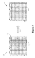
- FIG. 3 conceptually illustrates a first exemplary embodiment of a method of modifying a pattern of resource elements allocated to a first type of reference symbols.
- a resource block 300 includes 12 subcarriers that are numbered ( 0 - 11 ) along the vertical axis and 14 time intervals that are numbered ( 0 - 13 ) along the horizontal axis. Each small square corresponds to one resource element that can be used to transmit one symbol and individual resource elements can be indicated using the convention (subcarrier number, time interval number).
- a first type of reference symbol is allocated to the pattern of resource elements indicated by the dashed boxes 305 .
- a second type of reference symbols is allocated to the resource elements indicated by the boldfaced box 310 .
- the antenna ports allocated to each resource element for transmission of the corresponding reference symbol are indicated by the number in the resource element box.
- resource elements for the first type of reference symbol are allocated two antenna ports ( 0 , 1 ) and resource elements for the second type of reference symbol are allocated four antenna ports ( 0 - 3 ).
- the first type of symbol can be transmitted using antenna ports 0 , 1 for the resource elements ( 0 , 5 ) and ( 0 , 6 ), respectively.
- the resource element patterns 305 , 310 may be used for communication over air interfaces as long as no relay nodes are present in the communication path between the base station and user equipment. However, if one or more relay nodes are present in the communication path, communication nodes in the communication path may use modified resource element patterns to accommodate symbols that are reserved for mode switching at the relay node. In the illustrated embodiment, the last symbol ( 13 ) is reserved for mode switching when a relay node is present in the communication path. In the illustrated embodiment, the pattern 305 is modified (as indicated by the arrow 315 ) by shifting the resource elements for the first type of reference symbol from symbols 12 - 13 to a modified resource element pattern 320 that includes symbols 9 - 10 , as shown in the modified resource block 325 .
- the boldfaced box indicating the resource elements allocated to the second type of reference symbols is not shown in the resource block 325 . However, these resource elements remain allocated to the second type of reference symbols in the illustrated embodiment.
- the second type of symbol may therefore be transmitted in these symbols using the antenna ports indicated in resource block 300 regardless of whether the first type of symbols are transmitted in any of the resource blocks corresponding to symbols 9 - 10 .
- Performing the shift of the resource element pattern 305 causes the resource elements allocated to the first type of reference symbol to collide with the second type of reference symbols that have already been allocated symbols 9 - 10 .
- the different types of reference symbols may be encoded with different coding sequences, such as different Walsh codes, and so it may be theoretically possible to transmit them in the same reference elements.
- the complexities of decoding different sequences transmitted from different antenna ports over different air interface channels may make it difficult or impossible to accurately estimate the transfer function and demodulate/decode the different reference symbols in practice.
- FIG. 4 conceptually illustrates a second exemplary embodiment of a method of modifying a pattern of resource elements allocated to a first type of reference symbols.
- a resource block 400 includes 12 subcarriers and 14 time intervals that define resource elements that can be used to transmit one symbol, as discussed herein.
- First and second reference symbols can be allocated corresponding patterns 405 , 410 of resource elements when no relay nodes are present in the communication path.
- the antenna ports allocated to each resource element for transmission of the corresponding reference symbol are indicated by the number in the resource element box.
- the resource elements for the first type of reference symbols are allocated two antenna ports ( 0 , 1 ) and the resource elements for the second type of reference symbols are allocated four antenna ports ( 0 - 3 ).
- the resource element pattern 405 used by the first type of reference symbols may be modified (as indicated by the arrow 415 ) to accommodate a finite mode switching time, as shown in the resource block 420 .
- the modified resource element pattern 425 includes resource elements that are selected based upon the antenna ports that are used to transmit the first and second type of reference symbols. Nodes in the communication path can compare the antenna ports used to transmit different types of reference symbols in overlapping resource elements. The different reference symbols may be allocated to the overlapping resource elements when the same antenna port is allocated for transmission of the different reference symbols.
- a comparison of the antenna ports allocated to these resource elements indicates that the first and second type of reference symbols are transmitted over antenna port 0 in resource element ( 0 , 9 ) and antenna port 1 in resource element ( 0 , 10 ).
- the reference symbols share the same air interface channels so the transfer function can be estimated and the symbols can be demodulated/decoded by the receiver in a straightforward manner when they are transmitted concurrently using different coding sequences.
- the first type of reference symbol after a shift, the first type of reference symbol would be transmitted over antenna port 0 in resource element ( 10 , 9 ) and antenna port 1 in resource element ( 10 , 10 ).
- the second type of reference symbol is transmitted over antenna port 2 in resource element ( 10 , 9 ) and antenna port 3 in resource element ( 10 , 10 ).
- a comparison of the antenna ports reveals that the first and second types of reference symbols would be allocated different antenna ports in these overlapping resource elements.
- the reference symbols therefore would not share the same air interface channels and would have different transfer functions. Consequently, the reference symbols would be very difficult or impossible to demodulate/decode when they are transmitted concurrently even though they may be encoded using different coding sequences.
- the pattern 425 may therefore be modified by dropping or de-allocating the resource elements ( 10 , 9 ) and ( 10 , 10 ).
- the boldfaced box 410 is not depicted in the resource block 420 but the symbols 9 , 10 remain allocated to the second type of reference symbol.
- the first type of reference symbol is bypassed for transmission in the resource elements ( 10 , 9 ) and ( 10 , 10 )
- the second type of reference symbol may still be transmitted in these resource elements.
- FIG. 5 conceptually illustrates a third exemplary embodiment of a method of modifying a pattern of resource elements allocated to a first type of reference symbols.
- a resource block 500 includes 12 subcarriers and 14 time intervals that define resource elements that can be used to transmit one symbol, as discussed herein.
- First and second reference symbols can be allocated corresponding patterns 505 , 510 of resource elements when no relay nodes are present in the communication path.
- the antenna ports allocated to each resource element for transmission of the corresponding reference symbol are indicated by the number in the resource element box.
- resource elements for the first type of reference symbols are allocated four antenna ports ( 0 - 3 ) and the resource elements for the second type of reference symbols are allocated four antenna ports ( 0 - 3 ).
- the resource element pattern 505 used by the first type of reference symbols may be modified (as indicated by the arrow 515 ) to accommodate a finite mode switching time, as shown in the resource block 520 .
- the modified resource element pattern 525 includes resource elements that are selected based upon the antenna ports that are used to transmit the first and second type of reference symbols. Nodes in the communication path can compare the antenna ports used to transmit different types of reference symbols in overlapping resource elements. The different reference symbols may be allocated to the overlapping resource elements when the same antenna ports are allocated for transmission of the different reference symbols.
- a comparison of the antenna ports allocated to these resource elements indicates that the first and second type of reference symbols are transmitted over antenna port 0 in resource element ( 5 , 9 ), antenna port 1 in resource element ( 5 , 10 ), antenna port 2 in resource element ( 6 , 9 ), and antenna port 3 in resource element ( 6 , 10 ).
- the reference symbols therefore share the same antenna ports and air interface channels and can be demodulated and/or decoded by the receiver in a straightforward manner when they are transmitted concurrently using different coding sequences.
- the first type of reference symbol would be transmitted over antenna port 0 in resource element ( 0 , 9 ), antenna port 1 in resource element ( 0 , 10 ), antenna port 2 in resource element ( 1 , 9 ), and antenna port 3 in resource element ( 1 , 10 ).
- the second type of reference symbol is transmitted over antenna port 0 in resource element ( 0 , 9 ), antenna port 1 in resource element ( 0 , 10 ), antenna port 0 in resource element ( 1 , 9 ), and antenna port 1 in resource element ( 1 , 10 ).
- a comparison of the antenna ports therefore reveals that the first and second types of reference symbols would be allocated different antenna ports in the overlapping resource elements.
- the reference symbols therefore would not share the same air interface channels and would be very difficult or impossible to decode when they are transmitted concurrently even though they may be encoded using different coding sequences.
- the pattern 525 may therefore be modified by dropping or de-allocating the resource elements ( 0 , 9 ), ( 0 , 10 ), ( 1 , 9 ), and ( 1 , 10 ).
- the boldfaced box 510 is not depicted in the resource block 520 but the symbols 9 , 10 remain allocated to the second type of reference symbol.
- the second type of reference symbol is still transmitted in these resource elements.
- FIG. 6 conceptually illustrates a fourth exemplary embodiment of a method of modifying a pattern of resource elements allocated to a first type of reference symbols.
- a resource block 600 includes 12 subcarriers and 14 time intervals that define resource elements that can be used to transmit symbols, as discussed herein.
- First and second types of reference symbols can be allocated corresponding patterns 605 , 610 of resource elements when no relay nodes are present in the communication path.
- the antenna ports allocated to each resource element for transmission of the corresponding reference symbol are indicated by the number in the resource element box.
- the resource elements for the first type of reference symbols are allocated two antenna ports ( 0 , 1 ) and the resource elements for the second type of reference symbols are allocated eight antenna ports ( 0 - 7 ).
- the resource element pattern 605 used by the first type of reference symbols may be modified (as indicated by the arrow 615 ) to accommodate a finite mode switching time, as shown in the resource block 620 .
- the modified resource element pattern 625 includes resource elements that are selected based upon the antenna ports that are used to transmit the first and second type of reference symbols. Nodes in the communication path can compare the antenna ports used to transmit different types of reference symbols in overlapping resource elements. The different reference symbols may be allocated to the overlapping resource elements when the same antenna port is allocated for transmission of the different reference symbols.
- a comparison of the antenna ports allocated to these resource elements indicates that the first and second type of reference symbols are transmitted over antenna port 0 in resource element ( 0 , 9 ) and antenna port 1 in resource element ( 0 , 10 ).
- the reference symbols therefore share the same air interface channels and can be decoded by the receiver in a straightforward manner when they are transmitted concurrently using different coding sequences.
- the first type of reference symbol would be transmitted over antenna port 0 in resource elements ( 5 , 9 ), ( 10 , 9 ) and antenna port 1 in resource elements ( 5 , 10 ), ( 10 , 10 ).
- the second type of reference symbol is transmitted over antenna port 4 in resource element ( 5 , 9 ), antenna port 5 in resource element ( 5 , 10 ), antenna port 2 in resource element ( 10 , 9 ), and antenna port 3 in resource element ( 10 , 10 ).
- a comparison of the antenna ports therefore reveals that the first and second types of reference symbols would be allocated different antenna ports in the overlapping resource elements ( 5 , 9 ), ( 5 , 10 ), ( 10 , 9 ), ( 10 , 10 ).
- the reference symbols therefore would not share the same air interface channels and would be very difficult or impossible to decode when they are transmitted concurrently even though they may be encoded using different coding sequences.
- the pattern 625 may therefore be modified by dropping or de-allocating the resource elements ( 5 , 9 ), ( 5 , 10 ), ( 10 , 9 ), ( 10 , 10 ).
- the boldfaced box 610 is not depicted in the resource block 620 but the symbols 9 , 10 remain allocated to the second type of reference symbol.
- the first type of reference symbol is bypassed for transmission in the resource elements ( 5 , 9 ), ( 5 , 10 ), ( 10 , 9 ), ( 10 , 10 )
- the second type of reference symbol is still transmitted in these resource elements.
- Embodiments of the techniques described herein may allow multiple stages of reduction of the number of resource elements in the first reference symbol pattern.
- the degree of reduction may depend on how many resource elements may be removed in order for the remaining resource elements to match a second reference symbol pattern and pattern of antenna ports.
- Selectively removing resource elements from the set that is allocated to a particular type of reference symbol may increase the total reference symbol energy available relative to embodiments that simply remove reference elements that conflict with symbols reserved for mode switching.
- selectively removing resource elements may prevent collisions between different types of reference symbols. These collisions may make it difficult or impossible to receive either type of reference symbol in reference elements that are experiencing a collision and so selectively removing the resource elements when the reference symbols do not share an antenna port may improve the overall performance of the system.
- the software implemented aspects of the disclosed subject matter are typically encoded on some form of program storage medium or implemented over some type of transmission medium.
- the program storage medium may be magnetic (e.g., a floppy disk or a hard drive) or optical (e.g., a compact disk read only memory, or “CD ROM”), and may be read only or random access.
- the transmission medium may be twisted wire pairs, coaxial cable, optical fiber, or some other suitable transmission medium known to the art. The disclosed subject matter is not limited by these aspects of any given implementation.
Landscapes
- Engineering & Computer Science (AREA)
- Signal Processing (AREA)
- Computer Networks & Wireless Communication (AREA)
- Mobile Radio Communication Systems (AREA)
Abstract
Description
Claims (45)
Priority Applications (6)
| Application Number | Priority Date | Filing Date | Title |
|---|---|---|---|
| US13/205,931 US8842620B2 (en) | 2010-08-24 | 2011-08-09 | Method for accommodating overlapping reference signal patterns |
| PCT/US2011/048230 WO2012027189A1 (en) | 2010-08-24 | 2011-08-18 | Method for accommodating overlapping reference signal patterns |
| KR1020137007296A KR101468527B1 (en) | 2010-08-24 | 2011-08-18 | Method for accommodating overlapping reference signal patterns |
| JP2013526003A JP5501530B2 (en) | 2010-08-24 | 2011-08-18 | Method for dealing with overlapping reference signal patterns |
| EP11754572.3A EP2609709B1 (en) | 2010-08-24 | 2011-08-18 | Method for accommodating overlapping reference signal patterns |
| CN201180040932.3A CN103141052B (en) | 2010-08-24 | 2011-08-18 | For adapting to the method and apparatus of overlapped reference signal pattern |
Applications Claiming Priority (2)
| Application Number | Priority Date | Filing Date | Title |
|---|---|---|---|
| US40211310P | 2010-08-24 | 2010-08-24 | |
| US13/205,931 US8842620B2 (en) | 2010-08-24 | 2011-08-09 | Method for accommodating overlapping reference signal patterns |
Publications (2)
| Publication Number | Publication Date |
|---|---|
| US20120051404A1 US20120051404A1 (en) | 2012-03-01 |
| US8842620B2 true US8842620B2 (en) | 2014-09-23 |
Family
ID=44583446
Family Applications (1)
| Application Number | Title | Priority Date | Filing Date |
|---|---|---|---|
| US13/205,931 Active 2032-08-08 US8842620B2 (en) | 2010-08-24 | 2011-08-09 | Method for accommodating overlapping reference signal patterns |
Country Status (6)
| Country | Link |
|---|---|
| US (1) | US8842620B2 (en) |
| EP (1) | EP2609709B1 (en) |
| JP (1) | JP5501530B2 (en) |
| KR (1) | KR101468527B1 (en) |
| CN (1) | CN103141052B (en) |
| WO (1) | WO2012027189A1 (en) |
Cited By (3)
| Publication number | Priority date | Publication date | Assignee | Title |
|---|---|---|---|---|
| US20130182799A1 (en) * | 2012-01-13 | 2013-07-18 | Qualcomm Incorporated | Dm-rs based decoding using csi-rs-based timing |
| US10045363B2 (en) * | 2011-12-22 | 2018-08-07 | Airbus Ds Sas | HD-FDD method and system with no overlapping between downlink and uplink subframes |
| US10863367B2 (en) | 2011-06-03 | 2020-12-08 | Huawei Technologies Co., Ltd. | Reference signal sequence configuration method and network device |
Families Citing this family (9)
| Publication number | Priority date | Publication date | Assignee | Title |
|---|---|---|---|---|
| WO2014137197A2 (en) * | 2013-03-08 | 2014-09-12 | 인텔렉추얼디스커버리 주식회사 | Method and device for sending and receiving demodulation reference signal on new carrier type (nct) carrier |
| US10277375B2 (en) | 2013-03-19 | 2019-04-30 | Lg Electronics Inc. | Method and apparatus for transmitting ack/nack signals using multiple antenna ports |
| CN105375962B (en) * | 2014-08-25 | 2019-04-26 | 中兴通讯股份有限公司 | A kind of method sending and receiving reference signal and communication node |
| CN108282298B (en) * | 2017-01-06 | 2023-04-11 | 中兴通讯股份有限公司 | Reference signal transmission method and device |
| CN110892689A (en) * | 2017-07-13 | 2020-03-17 | 株式会社Ntt都科摩 | User terminal and wireless communication method |
| JP2019050469A (en) * | 2017-09-08 | 2019-03-28 | シャープ株式会社 | Base station device, terminal device, communication method, and integrated circuit |
| WO2020029182A1 (en) * | 2018-08-09 | 2020-02-13 | 株式会社Ntt都科摩 | Method and device for transmitting reference signal |
| CN113316909A (en) * | 2018-12-05 | 2021-08-27 | 瑞典爱立信有限公司 | Scalable method for obtaining UE-specific CSI |
| WO2023211192A1 (en) * | 2022-04-27 | 2023-11-02 | 엘지전자 주식회사 | Method and device for transmitting or receiving signal in wireless communication system |
Citations (6)
| Publication number | Priority date | Publication date | Assignee | Title |
|---|---|---|---|---|
| US20030202460A1 (en) * | 2002-04-26 | 2003-10-30 | Samsung Electronics Co., Ltd. | Apparatus and method for transmitting and receiving side information of a partial transmit sequence in an OFDM communication system |
| US20090196240A1 (en) * | 2008-02-04 | 2009-08-06 | Nokia Siemens Networks Oy | Method, apparatus and computer program to map a cyclic shift to a channel index |
| US20100238821A1 (en) * | 2009-03-17 | 2010-09-23 | Samsung Electronics Co., Ltd. | SYSTEM AND METHOD FOR DYNAMIC CELL SELECTION AND RESOURCE MAPPING FOR CoMP JOINT TRANSMISSION |
| US20100246376A1 (en) * | 2009-03-25 | 2010-09-30 | Samsung Electronics Co., Ltd. | Cell-specific shifting of reference signals in multi-stream transmissions |
| US20110170562A1 (en) * | 2010-01-12 | 2011-07-14 | Telefonaktiebolaget L M Ericsson (Publ) | Method and Apparatus for Channel Estimation and Detection in MIMO System |
| US20120106374A1 (en) * | 2010-05-04 | 2012-05-03 | Qualcomm Incorporated | Methods and apparatuses for using channel state information reference signals |
Family Cites Families (3)
| Publication number | Priority date | Publication date | Assignee | Title |
|---|---|---|---|---|
| CN101534507B (en) * | 2008-03-12 | 2014-04-16 | 株式会社Ntt都科摩 | Physical resource distributing method and device |
| CN101771437A (en) * | 2008-12-31 | 2010-07-07 | 中兴通讯股份有限公司 | Transmission method for dedicated pilot frequency |
| US9094167B2 (en) * | 2009-02-02 | 2015-07-28 | Samsung Electronics Co., Ltd. | System and method for multi-user and multi-cell MIMO transmissions |
-
2011
- 2011-08-09 US US13/205,931 patent/US8842620B2/en active Active
- 2011-08-18 EP EP11754572.3A patent/EP2609709B1/en active Active
- 2011-08-18 JP JP2013526003A patent/JP5501530B2/en not_active Expired - Fee Related
- 2011-08-18 KR KR1020137007296A patent/KR101468527B1/en not_active IP Right Cessation
- 2011-08-18 WO PCT/US2011/048230 patent/WO2012027189A1/en active Application Filing
- 2011-08-18 CN CN201180040932.3A patent/CN103141052B/en not_active Expired - Fee Related
Patent Citations (6)
| Publication number | Priority date | Publication date | Assignee | Title |
|---|---|---|---|---|
| US20030202460A1 (en) * | 2002-04-26 | 2003-10-30 | Samsung Electronics Co., Ltd. | Apparatus and method for transmitting and receiving side information of a partial transmit sequence in an OFDM communication system |
| US20090196240A1 (en) * | 2008-02-04 | 2009-08-06 | Nokia Siemens Networks Oy | Method, apparatus and computer program to map a cyclic shift to a channel index |
| US20100238821A1 (en) * | 2009-03-17 | 2010-09-23 | Samsung Electronics Co., Ltd. | SYSTEM AND METHOD FOR DYNAMIC CELL SELECTION AND RESOURCE MAPPING FOR CoMP JOINT TRANSMISSION |
| US20100246376A1 (en) * | 2009-03-25 | 2010-09-30 | Samsung Electronics Co., Ltd. | Cell-specific shifting of reference signals in multi-stream transmissions |
| US20110170562A1 (en) * | 2010-01-12 | 2011-07-14 | Telefonaktiebolaget L M Ericsson (Publ) | Method and Apparatus for Channel Estimation and Detection in MIMO System |
| US20120106374A1 (en) * | 2010-05-04 | 2012-05-03 | Qualcomm Incorporated | Methods and apparatuses for using channel state information reference signals |
Non-Patent Citations (7)
| Title |
|---|
| Alcatel-Lucent Shanghai Bell et al: "Un DM-RS Pattern for DL timing Case 3", 3GPP Draft; R1-104408, 3rd Generation Partnership Project (3GPP), Mobile Competence Centre ; 650, Route Des Lucioles ; F-06921 Sophia-Antipolis Cedex ; France, vol. RAN WG1, no. Madrid, Spain; Aug. 23, 2010, Aug. 17, 2010, XP050449746, [retrieved on Aug. 17, 2010] the whole document. |
| International Application PCT/US2011/048230 dated Nov. 3, 2011. |
| Nokia, Further considerations on UE-specific reference symbol multiplexing for LTE-Advanced downlink;3GPP TSG RAN WG1 Meeting #57 R1-091757 San Francisco, USA, May 4-8, 2009. * |
| NTT DOCOMO: "DM-RS Design for Backhaul 1-19 Link", 3GPP Draft; RI-I04939 DM-RS for UN Link, 3rd Generation Partnership Project (3GPP),Mobile Competence Centre , 650, Route Des Lucioles , F-06921 Sophia-Antipolis Cedex , France, vol. RAN WG1, no. Madrid, Spain; Aug. 23, 2010, Aug. 17, 2010, XP050450078,[retrieved on Aug. 17, 2010] the whole document. |
| NTT DOCOMO: "Intra-cell CSI-RS Design", 3GPP Draft; R1-104199 Intra Cell CSI RS, 3rd Generation Partnership Project (3GPP), Mobile Competence Centre ; 650, Route Des Lucioles ; F-06921 Sophia-Antipolis Cedex ; France, vol. RAN WG1, no. Dresden, Germany; Jun. 28, 2010, Jul. 5, 2010, XP050449617, [retrieved on Jul. 5, 2010] the whole document. |
| Written Opinion. |
| Zte et al: "Performance Evaluation of UN DMRS", 3GPP Draft; R1-104561 UN DMRS, 3rd Generation Partnership Project (3GPP), Mobile Competence Centre ; 650, Route Des Lucioles ; F-06921 Sophia-Antipolis Cedex ; France, vol. RAN WG1, no. Madrid, Spain; Aug. 23, 2010, Aug. 17, 2010, XP050449858,[retrieved on Aug. 17, 2010] the whole document. |
Cited By (4)
| Publication number | Priority date | Publication date | Assignee | Title |
|---|---|---|---|---|
| US10863367B2 (en) | 2011-06-03 | 2020-12-08 | Huawei Technologies Co., Ltd. | Reference signal sequence configuration method and network device |
| US10045363B2 (en) * | 2011-12-22 | 2018-08-07 | Airbus Ds Sas | HD-FDD method and system with no overlapping between downlink and uplink subframes |
| US20130182799A1 (en) * | 2012-01-13 | 2013-07-18 | Qualcomm Incorporated | Dm-rs based decoding using csi-rs-based timing |
| US9374253B2 (en) * | 2012-01-13 | 2016-06-21 | Qualcomm Incorporated | DM-RS based decoding using CSI-RS-based timing |
Also Published As
| Publication number | Publication date |
|---|---|
| KR20130045400A (en) | 2013-05-03 |
| WO2012027189A1 (en) | 2012-03-01 |
| EP2609709B1 (en) | 2016-11-16 |
| JP2013536653A (en) | 2013-09-19 |
| US20120051404A1 (en) | 2012-03-01 |
| CN103141052A (en) | 2013-06-05 |
| KR101468527B1 (en) | 2014-12-03 |
| EP2609709A1 (en) | 2013-07-03 |
| JP5501530B2 (en) | 2014-05-21 |
| CN103141052B (en) | 2016-03-23 |
Similar Documents
| Publication | Publication Date | Title |
|---|---|---|
| US8842620B2 (en) | Method for accommodating overlapping reference signal patterns | |
| US11576198B2 (en) | Method and apparatus for transmitting remaining minimum system information in multibeam-based system | |
| CN103843433B9 (en) | wireless communication control channel system and method | |
| US11824805B2 (en) | Transmitter, receiver, transmission method, and reception method with phase tracking reference signal mapping | |
| EP2792096B1 (en) | Method for generating and transmitting demodulation reference signals | |
| CN103026674B (en) | Use the method, apparatus and system of reference signal in the communications | |
| EP3410799B1 (en) | Signaling of reference signal patterns for downlink channel decoding | |
| CN108076520B (en) | Method and equipment used in UE and base station | |
| CN106411486B (en) | Method and device for sending and receiving uplink demodulation pilot frequency | |
| CN105580467A (en) | Terminal apparatus, base station apparatus, communication system, communication method, and integrated circuit | |
| CN104272639B (en) | method for transmitting control channel signal | |
| JP2013529008A (en) | Transmitter, receiver and method for downlink control signaling | |
| CN102315870A (en) | Downlink control information (DCI) indication method and apparatus thereof | |
| EP2828980A1 (en) | Control signaling for downlink coordinated multipoint wireless communication | |
| KR20140145159A (en) | Method and device for allocating and detecting downlink control channel resources | |
| BRPI0718366A2 (en) | ORTOGONALIZATION OF BALIZA SYMBOLS | |
| EP2745482B1 (en) | Flexible transmission of messages in a wireless communication system | |
| CA3148743A1 (en) | Receiving device, transmitting device, receiving method, and transmitting method | |
| US20120182959A1 (en) | Method and apparatus for transceiving data in a wireless communication system | |
| RU2597219C2 (en) | Method and apparatus for transmitting and receiving signal in distributed antenna system | |
| US8976899B2 (en) | Apparatus and method for transmitting/receiving data in mobile communication system |
Legal Events
| Date | Code | Title | Description |
|---|---|---|---|
| AS | Assignment |
Owner name: ALCATEL-LUCENT U.S.A. INC., NEW JERSEY Free format text: ASSIGNMENT OF ASSIGNORS INTEREST;ASSIGNOR:HU, TECK;REEL/FRAME:026720/0759 Effective date: 20110809 Owner name: ALCATEL-LUCENT TELECOM LTD., UNITED KINGDOM Free format text: ASSIGNMENT OF ASSIGNORS INTEREST;ASSIGNOR:BAKER, MATTHEW;REEL/FRAME:026720/0700 Effective date: 20110809 |
|
| AS | Assignment |
Owner name: ALCATEL LUCENT, FRANCE Free format text: ASSIGNMENT OF ASSIGNORS INTEREST;ASSIGNOR:ALCATEL-LUCENT USA INC.;REEL/FRAME:028969/0884 Effective date: 20120913 Owner name: ALCATEL LUCENT, FRANCE Free format text: ASSIGNMENT OF ASSIGNORS INTEREST;ASSIGNOR:ALCATEL-LUCENT TELECOM LTD.;REEL/FRAME:028970/0005 Effective date: 20120913 |
|
| AS | Assignment |
Owner name: CREDIT SUISSE AG, NEW YORK Free format text: SECURITY AGREEMENT;ASSIGNOR:LUCENT, ALCATEL;REEL/FRAME:029821/0001 Effective date: 20130130 Owner name: CREDIT SUISSE AG, NEW YORK Free format text: SECURITY AGREEMENT;ASSIGNOR:ALCATEL LUCENT;REEL/FRAME:029821/0001 Effective date: 20130130 |
|
| FEPP | Fee payment procedure |
Free format text: PAYOR NUMBER ASSIGNED (ORIGINAL EVENT CODE: ASPN); ENTITY STATUS OF PATENT OWNER: LARGE ENTITY |
|
| STCF | Information on status: patent grant |
Free format text: PATENTED CASE |
|
| AS | Assignment |
Owner name: ALCATEL LUCENT, FRANCE Free format text: RELEASE BY SECURED PARTY;ASSIGNOR:CREDIT SUISSE AG;REEL/FRAME:033868/0555 Effective date: 20140819 |
|
| FEPP | Fee payment procedure |
Free format text: PAYER NUMBER DE-ASSIGNED (ORIGINAL EVENT CODE: RMPN); ENTITY STATUS OF PATENT OWNER: LARGE ENTITY Free format text: PAYOR NUMBER ASSIGNED (ORIGINAL EVENT CODE: ASPN); ENTITY STATUS OF PATENT OWNER: LARGE ENTITY |
|
| AS | Assignment |
Owner name: OMEGA CREDIT OPPORTUNITIES MASTER FUND, LP, NEW YORK Free format text: SECURITY INTEREST;ASSIGNOR:WSOU INVESTMENTS, LLC;REEL/FRAME:043966/0574 Effective date: 20170822 Owner name: OMEGA CREDIT OPPORTUNITIES MASTER FUND, LP, NEW YO Free format text: SECURITY INTEREST;ASSIGNOR:WSOU INVESTMENTS, LLC;REEL/FRAME:043966/0574 Effective date: 20170822 |
|
| AS | Assignment |
Owner name: WSOU INVESTMENTS, LLC, CALIFORNIA Free format text: ASSIGNMENT OF ASSIGNORS INTEREST;ASSIGNOR:ALCATEL LUCENT;REEL/FRAME:044000/0053 Effective date: 20170722 |
|
| FEPP | Fee payment procedure |
Free format text: MAINTENANCE FEE REMINDER MAILED (ORIGINAL EVENT CODE: REM.) |
|
| FEPP | Fee payment procedure |
Free format text: SURCHARGE FOR LATE PAYMENT, LARGE ENTITY (ORIGINAL EVENT CODE: M1554); ENTITY STATUS OF PATENT OWNER: LARGE ENTITY |
|
| MAFP | Maintenance fee payment |
Free format text: PAYMENT OF MAINTENANCE FEE, 4TH YEAR, LARGE ENTITY (ORIGINAL EVENT CODE: M1551); ENTITY STATUS OF PATENT OWNER: LARGE ENTITY Year of fee payment: 4 |
|
| AS | Assignment |
Owner name: BP FUNDING TRUST, SERIES SPL-VI, NEW YORK Free format text: SECURITY INTEREST;ASSIGNOR:WSOU INVESTMENTS, LLC;REEL/FRAME:049235/0068 Effective date: 20190516 |
|
| AS | Assignment |
Owner name: WSOU INVESTMENTS, LLC, CALIFORNIA Free format text: RELEASE BY SECURED PARTY;ASSIGNOR:OCO OPPORTUNITIES MASTER FUND, L.P. (F/K/A OMEGA CREDIT OPPORTUNITIES MASTER FUND LP;REEL/FRAME:049246/0405 Effective date: 20190516 |
|
| AS | Assignment |
Owner name: OT WSOU TERRIER HOLDINGS, LLC, CALIFORNIA Free format text: SECURITY INTEREST;ASSIGNOR:WSOU INVESTMENTS, LLC;REEL/FRAME:056990/0081 Effective date: 20210528 |
|
| AS | Assignment |
Owner name: WSOU INVESTMENTS, LLC, CALIFORNIA Free format text: RELEASE BY SECURED PARTY;ASSIGNOR:TERRIER SSC, LLC;REEL/FRAME:056526/0093 Effective date: 20210528 |
|
| FEPP | Fee payment procedure |
Free format text: MAINTENANCE FEE REMINDER MAILED (ORIGINAL EVENT CODE: REM.); ENTITY STATUS OF PATENT OWNER: LARGE ENTITY |
|
| FEPP | Fee payment procedure |
Free format text: 7.5 YR SURCHARGE - LATE PMT W/IN 6 MO, LARGE ENTITY (ORIGINAL EVENT CODE: M1555); ENTITY STATUS OF PATENT OWNER: LARGE ENTITY |
|
| MAFP | Maintenance fee payment |
Free format text: PAYMENT OF MAINTENANCE FEE, 8TH YEAR, LARGE ENTITY (ORIGINAL EVENT CODE: M1552); ENTITY STATUS OF PATENT OWNER: LARGE ENTITY Year of fee payment: 8 |