CN110892689A - User terminal and wireless communication method - Google Patents
User terminal and wireless communication method Download PDFInfo
- Publication number
- CN110892689A CN110892689A CN201780093111.3A CN201780093111A CN110892689A CN 110892689 A CN110892689 A CN 110892689A CN 201780093111 A CN201780093111 A CN 201780093111A CN 110892689 A CN110892689 A CN 110892689A
- Authority
- CN
- China
- Prior art keywords
- resource
- signal
- dmrs
- data
- transmission
- Prior art date
- Legal status (The legal status is an assumption and is not a legal conclusion. Google has not performed a legal analysis and makes no representation as to the accuracy of the status listed.)
- Pending
Links
- 238000000034 method Methods 0.000 title claims description 80
- 238000004891 communication Methods 0.000 title claims description 55
- 230000005540 biological transmission Effects 0.000 claims abstract description 114
- 230000008859 change Effects 0.000 claims abstract description 15
- 230000011664 signaling Effects 0.000 claims description 36
- 230000006866 deterioration Effects 0.000 abstract description 4
- 238000012545 processing Methods 0.000 description 78
- 238000005259 measurement Methods 0.000 description 37
- 238000010586 diagram Methods 0.000 description 20
- 238000013507 mapping Methods 0.000 description 14
- 238000010295 mobile communication Methods 0.000 description 9
- 238000005516 engineering process Methods 0.000 description 7
- 230000006870 function Effects 0.000 description 6
- 238000007726 management method Methods 0.000 description 6
- 230000007274 generation of a signal involved in cell-cell signaling Effects 0.000 description 5
- 230000008569 process Effects 0.000 description 4
- 230000007774 longterm Effects 0.000 description 3
- 238000012986 modification Methods 0.000 description 3
- 230000004048 modification Effects 0.000 description 3
- 230000003287 optical effect Effects 0.000 description 3
- 101000741965 Homo sapiens Inactive tyrosine-protein kinase PRAG1 Proteins 0.000 description 2
- 102100038659 Inactive tyrosine-protein kinase PRAG1 Human genes 0.000 description 2
- 230000006978 adaptation Effects 0.000 description 2
- 238000012937 correction Methods 0.000 description 2
- 230000008878 coupling Effects 0.000 description 2
- 238000010168 coupling process Methods 0.000 description 2
- 238000005859 coupling reaction Methods 0.000 description 2
- 125000004122 cyclic group Chemical group 0.000 description 2
- 230000000670 limiting effect Effects 0.000 description 2
- 239000013307 optical fiber Substances 0.000 description 2
- 230000002829 reductive effect Effects 0.000 description 2
- 238000013468 resource allocation Methods 0.000 description 2
- 230000003068 static effect Effects 0.000 description 2
- 238000012546 transfer Methods 0.000 description 2
- 208000037918 transfusion-transmitted disease Diseases 0.000 description 2
- 230000002776 aggregation Effects 0.000 description 1
- 238000004220 aggregation Methods 0.000 description 1
- 238000004364 calculation method Methods 0.000 description 1
- 239000000969 carrier Substances 0.000 description 1
- 230000015556 catabolic process Effects 0.000 description 1
- 238000006243 chemical reaction Methods 0.000 description 1
- 239000003795 chemical substances by application Substances 0.000 description 1
- 238000012790 confirmation Methods 0.000 description 1
- 239000000470 constituent Substances 0.000 description 1
- 238000010276 construction Methods 0.000 description 1
- 230000008094 contradictory effect Effects 0.000 description 1
- 238000006731 degradation reaction Methods 0.000 description 1
- 230000001419 dependent effect Effects 0.000 description 1
- 238000009795 derivation Methods 0.000 description 1
- 230000009977 dual effect Effects 0.000 description 1
- 230000000694 effects Effects 0.000 description 1
- 239000000835 fiber Substances 0.000 description 1
- 238000001914 filtration Methods 0.000 description 1
- 238000011835 investigation Methods 0.000 description 1
- 230000036961 partial effect Effects 0.000 description 1
- 239000002245 particle Substances 0.000 description 1
- 230000002093 peripheral effect Effects 0.000 description 1
- 230000029058 respiratory gaseous exchange Effects 0.000 description 1
- 230000011218 segmentation Effects 0.000 description 1
- 238000011144 upstream manufacturing Methods 0.000 description 1
Images


Classifications
-
- H—ELECTRICITY
- H04—ELECTRIC COMMUNICATION TECHNIQUE
- H04L—TRANSMISSION OF DIGITAL INFORMATION, e.g. TELEGRAPHIC COMMUNICATION
- H04L27/00—Modulated-carrier systems
- H04L27/26—Systems using multi-frequency codes
- H04L27/2601—Multicarrier modulation systems
- H04L27/2602—Signal structure
-
- H—ELECTRICITY
- H04—ELECTRIC COMMUNICATION TECHNIQUE
- H04L—TRANSMISSION OF DIGITAL INFORMATION, e.g. TELEGRAPHIC COMMUNICATION
- H04L27/00—Modulated-carrier systems
- H04L27/26—Systems using multi-frequency codes
-
- H—ELECTRICITY
- H04—ELECTRIC COMMUNICATION TECHNIQUE
- H04L—TRANSMISSION OF DIGITAL INFORMATION, e.g. TELEGRAPHIC COMMUNICATION
- H04L27/00—Modulated-carrier systems
- H04L27/26—Systems using multi-frequency codes
- H04L27/2601—Multicarrier modulation systems
- H04L27/2602—Signal structure
- H04L27/261—Details of reference signals
- H04L27/2613—Structure of the reference signals
-
- H—ELECTRICITY
- H04—ELECTRIC COMMUNICATION TECHNIQUE
- H04L—TRANSMISSION OF DIGITAL INFORMATION, e.g. TELEGRAPHIC COMMUNICATION
- H04L5/00—Arrangements affording multiple use of the transmission path
- H04L5/003—Arrangements for allocating sub-channels of the transmission path
- H04L5/0048—Allocation of pilot signals, i.e. of signals known to the receiver
- H04L5/0051—Allocation of pilot signals, i.e. of signals known to the receiver of dedicated pilots, i.e. pilots destined for a single user or terminal
-
- H—ELECTRICITY
- H04—ELECTRIC COMMUNICATION TECHNIQUE
- H04L—TRANSMISSION OF DIGITAL INFORMATION, e.g. TELEGRAPHIC COMMUNICATION
- H04L5/00—Arrangements affording multiple use of the transmission path
- H04L5/0091—Signaling for the administration of the divided path
- H04L5/0096—Indication of changes in allocation
-
- H—ELECTRICITY
- H04—ELECTRIC COMMUNICATION TECHNIQUE
- H04W—WIRELESS COMMUNICATION NETWORKS
- H04W56/00—Synchronisation arrangements
- H04W56/001—Synchronization between nodes
-
- H—ELECTRICITY
- H04—ELECTRIC COMMUNICATION TECHNIQUE
- H04W—WIRELESS COMMUNICATION NETWORKS
- H04W72/00—Local resource management
- H04W72/04—Wireless resource allocation
- H04W72/044—Wireless resource allocation based on the type of the allocated resource
- H04W72/0446—Resources in time domain, e.g. slots or frames
-
- H—ELECTRICITY
- H04—ELECTRIC COMMUNICATION TECHNIQUE
- H04W—WIRELESS COMMUNICATION NETWORKS
- H04W72/00—Local resource management
- H04W72/30—Resource management for broadcast services
-
- H—ELECTRICITY
- H04—ELECTRIC COMMUNICATION TECHNIQUE
- H04W—WIRELESS COMMUNICATION NETWORKS
- H04W72/00—Local resource management
- H04W72/50—Allocation or scheduling criteria for wireless resources
- H04W72/54—Allocation or scheduling criteria for wireless resources based on quality criteria
- H04W72/542—Allocation or scheduling criteria for wireless resources based on quality criteria using measured or perceived quality
-
- H—ELECTRICITY
- H04—ELECTRIC COMMUNICATION TECHNIQUE
- H04L—TRANSMISSION OF DIGITAL INFORMATION, e.g. TELEGRAPHIC COMMUNICATION
- H04L27/00—Modulated-carrier systems
- H04L27/26—Systems using multi-frequency codes
- H04L27/2601—Multicarrier modulation systems
- H04L27/2602—Signal structure
- H04L27/261—Details of reference signals
- H04L27/2613—Structure of the reference signals
- H04L27/26134—Pilot insertion in the transmitter chain, e.g. pilot overlapping with data, insertion in time or frequency domain
Landscapes
- Engineering & Computer Science (AREA)
- Signal Processing (AREA)
- Computer Networks & Wireless Communication (AREA)
- Quality & Reliability (AREA)
- Mobile Radio Communication Systems (AREA)
- Input Circuits Of Receivers And Coupling Of Receivers And Audio Equipment (AREA)
Abstract
The performance deterioration due to the collision of the signals is suppressed. A user terminal according to an aspect of the present invention includes: a transmission/reception unit that transmits or receives a reference signal for data demodulation and a specific signal different from the reference signal for data demodulation; and a control unit configured to control a change of the first resource and/or the second resource based on notification information from a network when at least a part of the first resource set for the reference signal for data demodulation overlaps with at least a part of the second resource set for the specific signal.
Description
Technical Field
The present invention relates to a user terminal and a wireless communication method in a next generation mobile communication system.
Background
In a UMTS (Universal Mobile Telecommunications System) network, Long Term Evolution (LTE) is standardized for the purpose of higher data rate, lower latency, and the like (non-patent document 1). For the purpose of further increasing the bandwidth and speed of LTE (also referred to as LTE rel.8 or 9), LTE-a (also referred to as LTE advanced, LTE rel.10, 11 or 12) is standardized, and systems following LTE (for example, FRA (Future Radio Access)), 5G (fifth generation mobile communication system), 5G + (plus), NR (New Radio)), NX (New Radio Access)), FX (next generation Radio Access), LTE rel.13, 14 or 15 and the like) are also being studied.
In a conventional LTE system (e.g., LTE rel.8-13), communication is performed on the Downlink (DL) and/or Uplink (UL) using a subframe (also referred to as a Transmission Time Interval (TTI)) of 1 ms. This subframe is a transmission time unit of 1 data packet subjected to channel coding, and is a processing unit of scheduling, link adaptation, retransmission control (Hybrid Automatic repeat request), and the like.
The radio base station controls allocation (scheduling) of data to the user terminal, and notifies the user terminal of the scheduling of data by using Downlink Control Information (DCI). The user terminal controls reception of DL data and/or transmission of uplink data based on the DCI. Specifically, the user terminal receives downlink data in the same subframe as the DCI or transmits uplink data in a subframe after a predetermined period (for example, 4ms) of the DCI based on the DCI.
Documents of the prior art
Non-patent document
Non-patent document 1: 3GPP TS 36.300V8.12.0 "Evolved Universal Radio Access (E-UTRA) and Evolved Universal Radio Access Network (E-UTRAN); (ii) an Overall description; stage 2(Release 8) ", 4 months 2010
Disclosure of Invention
Problems to be solved by the invention
Future wireless communication systems (e.g., 5G, NR, etc. hereinafter abbreviated as NR) are expected to realize various wireless communication services so as to satisfy respective different requirements (e.g., ultra high speed, large capacity, ultra low delay, etc.).
For example, NR is being studied to provide a wireless Communication service called eMBB (enhanced Mobile BroadBand), mtc (large Machine Type Communication), URLLC (Ultra Reliable and Low Latency Communication), and the like.
Incidentally, in NR, it is under study to configure (map) signals not only fixedly for transmission time intervals (e.g., slots), but also flexibly.
In this case, it is considered that the configuration of the signal conflicts with the configuration of the other signals. Due to this collision, there is a possibility that deterioration in communication throughput, deterioration in reception quality, and the like occur.
The present invention has been made in view of the above-described circumstances, and an object thereof is to provide a user terminal and a radio communication method that suppress performance degradation due to signal collision.
Means for solving the problems
A user terminal according to an aspect of the present invention includes: a transmission/reception unit that transmits or receives a reference signal for data demodulation and a specific signal different from the reference signal for data demodulation; and a control unit configured to control a change of the first resource and/or the second resource based on notification information from a network when at least a part of the first resource set for the reference signal for data demodulation overlaps with at least a part of the second resource set for the specific signal.
Effects of the invention
According to the present invention, deterioration in performance due to signal collision can be suppressed.
Drawings
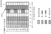
Fig. 1 is a diagram showing an example of signal arrangement by slot-based scheduling and non-slot-based scheduling.
Fig. 2 is a diagram illustrating an example of a configuration in which the second DMRS does not collide with the first specific signal.
Fig. 3A and 3B are diagrams illustrating an example of the collision avoidance method 1 a.
Fig. 4A and 4B are diagrams illustrating an example of the collision avoidance method 1B.
Fig. 5A and 5B are diagrams illustrating an example of the collision avoidance method 1 c.
Fig. 6A and 6B are diagrams illustrating an example of the collision avoidance method 2.
Fig. 7 is a diagram showing an example of a schematic configuration of a radio communication system according to an embodiment of the present invention.
Fig. 8 is a diagram showing an example of the overall configuration of a radio base station according to an embodiment of the present invention.
Fig. 9 is a diagram showing an example of a functional configuration of a radio base station according to an embodiment of the present invention.
Fig. 10 is a diagram showing an example of the overall configuration of a user terminal according to an embodiment of the present invention.
Fig. 11 is a diagram showing an example of a functional configuration of a user terminal according to an embodiment of the present invention.
Fig. 12 is a diagram showing an example of hardware configurations of a radio base station and a user terminal according to an embodiment of the present invention.
Detailed Description
For NR, multiple parameter sets may be supported in a specified carrier. The parameter set may be a communication parameter applied in Transmission and/or reception of a certain signal and/or channel, and may represent, for example, at least 1 of Sub-carrier spacing (SCS), bandwidth, symbol length, cyclic prefix length, TTI (Transmission time interval) length (e.g., subframe length, slot length), number of symbols per TTI, radio frame structure, filtering process, windowing process, and the like.
In addition, in NR, introduction of a time unit (for example, also referred to as a subframe, a slot, a mini-slot, a sub-slot, a TTI, a short TTI, a radio frame, or the like) that is the same as and/or different from an existing LTE system (for example, LTE rel.8-13) is being studied with support of a plurality of parameter sets, and the like.
Incidentally, in the conventional LTE system, a base station (e.g., may also be referred to as a bs (base station), an eNB, or the like) transmits Downlink Control Information (DCI) to a User Equipment (UE) using a Downlink Control channel (e.g., a PDCCH (Physical Downlink Control channel), an Enhanced PDCCH (EPDCCH, Enhanced PDCCH, or the like)). The term "transmit (receive) downlink control information" may also be replaced with "transmit (receive) downlink control channel".
The DCI may be scheduling information including at least 1 of resources (time and/or frequency resources) of scheduled data, transport block information, data modulation scheme information, transmission acknowledgement information (also referred to as retransmission control information, HARQ-ACK, ACK/NACK, and the like, for example), information related to a demodulation reference signal, and the like.
The DCI scheduling DL data reception and/or measurement of DL reference signals may also be referred to as DL allocation (or DL grant). The DCI that schedules UL data transmission and/or transmission of UL sounding (measurement) signals may also be referred to as a UL grant.
In NR, slot-based scheduling (slot-based scheduling) in which a pdsch (physical downlink Shared channel) or a pusch (physical Uplink Shared channel) is scheduled with a slot as a unit or reference of data allocation, and non-slot-based scheduling (non-slot-based scheduling) in which data is not scheduled using a slot as a unit or reference are being studied.
The non-slot-based scheduling may be mini-slot scheduling (mini-slot scheduling) for scheduling data for a mini-slot having a time length shorter than a slot, or may be scheduling data using other time resources such as 1 or more symbols as a unit or reference for data allocation.
Regardless of slot-based scheduling and/or non-slot-based scheduling, data and a DMRS (Demodulation Reference Signal) used for Demodulation of the data are arranged in the PDSCH and/or PUSCH.
In DL, the UE recognizes the position of a DMRS used for data demodulation of the PDSCH. In the case of slot-based scheduling, the position of the first DMRS used for demodulation of a certain PDSCH may be fixed to the 3 rd or 4th symbol of a slot, regardless of the PDSCH reception start/end symbol positions or the number of PDSCH symbols. The information about which one is mapped to the 3 rd or 4th channel may be implicitly notified based on the bandwidth of the scheduled PDSCH, the bandwidth of the PDCCH transmitting the DCI, or explicitly notified by higher layer signaling such as RRC signaling. In the case of non-slot-based scheduling, the position of the first DMRS used for demodulation of a certain PDSCH may be a relatively fixed position (e.g., the first symbol) with respect to the start position of the scheduled PDSCH, regardless of the start/end position of the scheduled PDSCH or the number of symbols of the PDSCH.
Similarly, in the UL, the UE recognizes the position of a DMRS used for data demodulation of the PUSCH. In the UL, the position of the first DMRS used for data demodulation of a certain PUSCH may be fixed relative to the start position of the scheduled PUSCH or may be fixed relative to the start position of the slot. The fixed position may be changed according to the scheduled PUSCH period.
Fig. 1 is a diagram showing an example of signal arrangement by slot-based scheduling and non-slot-based scheduling. The time length of the radio resource in this signal configuration is 1 slot (7 symbols, symbol # 1 to symbol #7), and the transmission bandwidth is 1 PRB (12 subcarriers, subcarrier # 1 to subcarrier # 12).
A DL control channel (PDCCH) is configured in the entire transmission band of symbols # 1 and # 2.
Further, first data (not shown) and a first DMRS used for demodulation of the first data are scheduled by slot-based scheduling. Here, the first DMRS is configured in the entire transmission band of symbol # 3.
Further, second data (not shown) and a second DMRS for demodulation of the second data are scheduled by non-slot-based scheduling. Here, the mini-slot is arranged across symbols # 6 and #7, the second DMRS for demodulation of the second data is arranged in the entire transmission band of the first symbol (symbol #6) of the mini-slot, and the second data is arranged in the entire transmission band of the second symbol (symbol #7) of the mini-slot. The mini slot may be a time unit including a predetermined symbol (for example, symbols # 6 and #7) in the slot, or may be a time unit that can be set to include an arbitrary continuous symbol (for example, symbol # 7 and symbol # 1 of the next slot) regardless of the slot.
The first DMRS, the first data, the second DMRS, and the second data may be DL or UL.
The DCI in the DL control channel may be used to indicate the scheduling of the first data and/or the second data in the same time slot and the same transmission band, or may be used to indicate the scheduling of the first data and/or the second data in other time slots and/or other transmission band. Further, the first data and/or the second data may also be scheduled by semi-persistent (semi-persistent) scheduling.
In addition, a DL control channel may be configured to symbols # 1 to #3, and a first DMRS may be configured to symbol # 4. In addition, the control resource set may be configured, and the DL control channel may be configured in a part of the control resource set.
In DL, a PBCH (Physical Broadcast Channel) is transmitted in a certain frequency position of a certain symbol. In the UL, a PRACH (Physical Random access channel) is transmitted in a certain frequency position of a certain symbol. All UEs may know the transmission opportunity (time resource) and the frequency location (frequency resource) of the channels of both the PBCH and the PRACH.
In DL, PSS (Primary Synchronization Signal), SSS (Secondary Synchronization Signal), and/or CSI-RS (channel state Information-Reference Signal) may be transmitted in a certain symbol. In UL, SRS (Sounding Reference Signal) may be transmitted in a certain symbol.
The above-mentioned channels and/or signals may be NR channels and/or signals, respectively.
The DMRS may also be referred to as a reference signal for data demodulation or a pilot signal. The CSI-RS and/or SRS may also be referred to as a channel information measurement reference signal, a channel state measurement reference signal, or a propagation path information measurement reference signal. The PSS and SSS may also be referred to as synchronization signals.
It is considered that collision between DMRS for PDSCH or PUSCH and other DL or UL channels and/or signals (e.g., at least one of PBCH, PRACH, PSS, SSS, CSI-RS, SRS) occurs due to such flexible configuration of channels and/or signals. In this case, it has not been decided how the UE operates.
Accordingly, the present inventors have studied a method for suppressing collision of a DMRS with other channels and/or signals, and have thus arrived at the present invention. Hereinafter, embodiments according to the present invention will be described in detail with reference to the drawings. The radio communication methods according to the respective embodiments may be applied individually or in combination.
The present invention is similarly applicable to a case where a slot is replaced with another time unit (e.g., a subframe, a mini slot, a symbol, a Transmission Time Interval (TTI), a short TTI, a radio frame, etc.).
(Wireless communication method)
< first embodiment >
In a first embodiment of the present invention, for specific channels (static channels) such as PBCH and/or PRACH and specific signals such as PSS, SSS, CSI-RS, and/or SRS, the UE is supposed to transmit or receive DMRS and specific channels and/or signals for which there is no collision between these specific channels and/or signals and DMRS. Hereinafter, a specific channel and/or signal is referred to as a specific signal in some cases.
The specific signal may be a channel and/or a signal required for the UE to access the network (cell search, random access, etc.).
For example, a network (e.g., a base station) may decide the location (resource) of the DMRS based on the location (resource) of the specific signal on the condition that the specific signal does not collide with the DMRS.
The Information related to the DMRS and the Information related to the specific signal may be notified (indicated) via dynamic physical layer signaling (e.g., DCI), may be notified (set) via semi-static and/or static higher layer signaling (e.g., RRC (Radio Resource Control) signaling, broadcast Information (Master Information Block (MIB), System Information Block (SIB: System Information Block), etc.), MAC (media access Control) signaling), or may be notified (set) to the UE using another signal or a combination thereof.
In the example of fig. 2, the network allocates a DL control channel in a radio resource of 1 PRB and 1 slot, as in fig. 1. Further, the network configures a first specific signal (e.g., CSI-RS, SRS) to symbol # 5. Further, the network schedules the first data and the first DMRS through slot-based scheduling. Here, the network configures a first DMRS in the entire transmission band region of symbol # 3.
Further, the network schedules the second DMRS and the second data through non-slot based scheduling. Here, the network decides time resources and/or frequency resources of the second DMRS so as to satisfy a condition that the second DMRS does not collide with the first specific signal. In other words, the network determines scheduling of data such that a resource (symbol #6) different from a resource (symbol #5) of the first specific signal becomes a resource of the second DMRS. By this operation, collision of the second DMRS with the first specific signal can be prevented.
In addition, the network may decide a resource different from the resource of the second DMRS as the resource of the first specific signal. The network may decide a resource different from that of the first specific signal as a resource of the first DMRS.
When DL data (PDSCH) is scheduled, the UE recognizes the DMRS resource, and performs data reception and DMRS-based channel estimation, assuming that the known first specific signal and the DMRS used for data demodulation are not arranged on the same resource. When UL data (PUSCH) is scheduled, the UE recognizes the DMRS resource, and transmits data and the DMRS, assuming that the known first specific signal and the DMRS used for data demodulation are not arranged in the same resource.
According to the first embodiment described above, by restricting the arrangement of signals by the network, it is possible to suppress the occurrence of collision of DMRS with a specific signal. Further, the amount of information of the signaling for suppressing collision can be suppressed. Further, since the UE assumes that the processing is performed without collision, the processing load can be suppressed.
< second embodiment >
In the second embodiment of the present invention, when a DMRS collides with a specific signal, the network and the UE change the resources of the DMRS and/or the specific signal to avoid the collision.
The following describes collision avoidance methods 1 and 2, which are examples of collision avoidance methods.
Method for avoiding collisions 1
In collision avoidance method 1, one of the 2 signals that collide is shifted in the frequency and/or time domain.
In DL, for example, DMRS or a specific signal (e.g., CSI-RS) may be shifted to another subcarrier (collision avoidance method 1 a). The shift may be to increase the subcarrier index of the target signal or to decrease the subcarrier index of the target signal.
In DL, for example, DMRS or a specific signal (e.g., CSI-RS) may also be shifted to another OFDM symbol (collision avoidance method 1 b). The shift may be to increase the symbol index of the target signal or to decrease the symbol index of the target signal.
In DL, for example, DMRS or a specific signal (e.g., CSI-RS) may also be shifted to other subcarriers and other OFDM symbols (collision avoidance method 1 c).
In the UL, for example, DMRS or a specific signal (e.g., SRS) is shifted to another subcarrier. The shift may be to increase the subcarrier index of the target signal or to decrease the subcarrier index of the target signal. In the UL, for example, a DMRS or a specific signal (e.g., SRS) is shifted to another OFDM symbol. The shift may be to increase the symbol index of the target signal or to decrease the symbol index of the target signal.
Collision avoidance methods 1a, 1b, and 1c, which are specific examples of the collision avoidance method 1, will be described below.
Fig. 3 illustrates an example of a collision avoidance method 1a for shifting a DMRS within a mini-slot in a time domain.
In the example of fig. 3A, a DL control channel and a first DMRS are arranged in the same manner as in fig. 1. Further, the first specific signal (CSI-RS or SRS) is arranged in the entire transmission band domain of symbol # 6.
Further, the second data and the second DMRS are scheduled by non-slot based scheduling. Here, the mini slots are arranged in symbols # 6 and #7, the second DMRS is arranged in the entire transmission band of the first symbol (symbol #6) of the mini slot, and the second data is arranged in the entire transmission band of symbol # 7. With this configuration, in symbol # 6, the second DMRS collides with the first specific signal.
In this case, as shown in fig. 3B, the collision avoidance method 1a reconfigures the second DMRS to symbol # 7 by shifting the second DMRS of symbol # 6 to a positive direction of the time domain by only 1 symbol. Further, the collision avoidance method 1a reconfigures the second data to symbol # 6 by shifting the second data of symbol # 7 by only 1 symbol to the negative direction of the time domain. That is, the collision avoidance method 1a exchanges the position of the second DMRS within the mini-slot with the position of the second data.
According to the collision avoidance method 1a described above, when the second DMRS is mapped in the entire transmission band and there is no gap in the same symbol, the second DMRS is shifted in the time domain, so that collision between the second DMRS and the first specific signal can be avoided.
Fig. 4 illustrates an example of a collision avoidance method 1b for shifting a DMRS within a mini-slot in a frequency domain.
In the example of fig. 4A, a DL control channel and a first DMRS are arranged in the same manner as in fig. 1. Further, the first specific signal (CSI-RS or SRS) is mapped to subcarriers # 1, #2, #5, #6, #9, and #10 of symbol # 6.
Further, the second data and the second DMRS are scheduled by non-slot based scheduling. Here, the mini slots are allocated to symbols # 6 and #7, a discontinuous second DMRS is allocated to subcarriers # 1, #2, #5, #6, #9, #10 of the first symbol (symbol #6) of the mini slot, and second data is allocated to subcarriers # 1, #2, #5, #6, #9, #10 of the second symbol (symbol #7) of the mini slot. With this configuration, in symbol # 6, the second DMRS collides with the first specific signal.
In this case, as shown in fig. 4B, the collision avoidance method 1B reconfigures the second DMRS to subcarriers # 3, #4, #7, #8, #11, #12 by shifting the second DMRS only 2 subcarriers in the positive direction of the frequency domain.
According to the collision avoidance method 1b described above, when the second DMRS is discontinuously arranged in the frequency domain or the like, there is a gap in the same symbol, the second DMRS is shifted in the frequency domain, so that collision between the second DMRS and the first specific signal can be avoided.
Fig. 5 illustrates an example of a collision avoidance method 1c for shifting DMRS in time and frequency domains.
In the example of fig. 5A, a DL control channel and a first DMRS are arranged in the same manner as in fig. 1. Further, a first specific signal (specific signal, e.g., CSI-RS or SRS) is arranged in the entire transmission band of symbol # 6, and a second specific signal (e.g., CSI-RS or SRS) is arranged in subcarriers # 1, #2, #5, #6, #9, #10 of symbol # 7.
Further, second data and a second DMRS are scheduled through non-slot based scheduling. Here, the mini slots are allocated to symbols # 6 and #7, discontinuous second DMRSs are allocated to subcarriers # 1, #2, #5, #6, #9, #10 of the first symbol (symbol #6) of the mini slot, and second data are allocated to subcarriers # 1, #2, #5, #6, #9, #10 of the second symbol (symbol #7) of the mini slot. With this configuration, in symbol # 6, the second DMRS collides with the first specific signal.
In this case, the collision avoidance method 1c reconfigures the second DMRS to symbol # 7 by shifting the second DMRS of symbol # 6 by only 1 symbol to the positive direction of the time domain.
Further, the collision avoidance method 1c reconfigures the second data to symbol # 6 by shifting the second data of symbol # 7 by only 1 symbol to the negative direction of the time domain. That is, the collision avoidance method 1c exchanges the position of the second DMRS within the mini-slot with the position of the second data.
In this state, collision of the second DMRS with the first specific signal can be avoided, but the second DMRS collides with the second specific signal.
Therefore, as shown in fig. 5B, further, the collision avoidance method 1c reconfigures the second DMRS to subcarriers # 3, #4, #7, #8, #11, #12 by shifting the second DMRS of symbol # 6 only by 2 subcarriers toward the positive direction of the frequency domain.
Further, the collision avoidance method 1c reconfigures the second data to the subcarriers # 3, #4, #7, #8, #11, #12 by shifting the second data of the symbol # 7 by only 2 subcarriers toward the positive direction of the frequency domain. That is, the collision avoidance method 1c performs the same frequency shift for the second DMRS and the second data within the mini-slot.
According to the collision avoidance method 1c described above, when the second DMRS is mapped in the entire transmission band and the like without any space in the same symbol, and when the second specific signal of another symbol is mapped discontinuously in the frequency domain and the like with any space in the symbol of the second specific signal, the second DMRS is shifted in the time domain and the frequency domain, so that collision between the second DMRS and the first specific signal and the second specific signal can be avoided.
In addition, the collision avoidance method 1 may perform a shift in the time domain and/or the frequency domain for both the DMRS and the specific signal. For example, part or all of the DMRS may be shifted, and part or all of the specific signal may be shifted, to avoid collision of the DMRS with the specific signal.
According to the collision avoidance method 1 above, collision of the second DMRS with a specific signal can be avoided by shifting the second DMRS in the time domain and/or the frequency domain.
Method for avoiding collisions 2
In collision avoidance method 2, DMRS is rate-matched around a specific signal (e.g., CSI-RS, SRS).
The sequence of the DMRS is decided according to a rate matching pattern of the DMRS on a symbol. For example, in the case where the result of rate matching of DMRS is to have X res (resource elements), a DMRS sequence of X samples is generated with a sequence having a sequence length of X samples or less. The sequence may be a CAZAC sequence (for example, Zadoff-Chu sequence) or a calculated sequence (computer-generated sequence). The sequence may be predefined by a standard. For example, a Zadoff-Chu sequence having a maximum prime number of X or less as a sequence length is cyclically spread to obtain DMRS sequences of X samples.
Fig. 6 shows an example of the collision avoidance method 2.
In the example of fig. 6A, a DL control channel and a first DMRS are arranged in the same manner as in fig. 1. Further, the first specific signal (CSI-RS or SRS) is mapped to subcarriers # 1, #2, #5, #6, #9, and #10 of symbols # 5 and # 6.
Further, the second data and the second DMRS are scheduled by non-slot based scheduling. Here, the mini slots are arranged in symbols # 6 and #7, the second DMRS is arranged in the entire transmission band of the first symbol (symbol #6) of the mini slot, and the second data is arranged in the entire transmission band of the second symbol (symbol #7) of the mini slot. With this configuration, the second DMRS collides with the first specific signal in subcarriers # 1, #2, #5, #6, #9, and #10 of symbol # 6.
In this case, as shown in fig. 6B, the collision avoidance method 2 rate-matches the second DMRS within the mini-slot around the first reference signal. That is, a new second DMRS is generated by reducing the sequence length of the second DMRS, and the new second DMRS is relocated to a resource excluding a resource in which the second DMRS overlaps with the first specific signal.
In the example of the figure, the resources of the second DMRS are reduced from 12 REs to 6 REs by rate matching. Therefore, while a sequence having a second DMRS sequence length of 12 or less is generated before rate matching, a sequence having a second DMRS sequence length of 6 or less is generated after rate matching.
Further, in case that the second DMRS is rate matched, the second data may also be rate matched. For example, the frequency resource of the rate-matched second data may be the same frequency resource as the rate-matched second DMRS.
In addition, the collision avoidance method 2 may perform rate matching for both the second DMRS and the first specific signal. For example, rate matching of the second DMRS may be performed in a certain portion of the repetition portion, and rate matching of the first specific signal may be performed in other portions of the repetition portion.
Further, the DMRS sequences of X samples may be obtained by another method such as using X consecutive samples in the DMRS sequence before rate matching as the DMRS sequence after rate matching, and using X consecutive samples in another sequence longer than X samples as the DMRS sequence after rate matching.
According to the collision avoidance method 2 described above, collision of the second DMRS and the first specific signal can be prevented. In addition, since it is not necessary to allocate a new resource to the second DMRS, it is possible to suppress an increase in processing and signaling of the network and the UE.
In addition, the network and the UE may also combine collision avoidance methods 1 and 2. For example, the rate matching of the second DMRS may also be performed after the time resources of the second DMRS are shifted.
In addition, when the first DMRS collides with the first specific signal and/or the second specific signal, the collision avoidance methods 1 and 2 may change the resource of the first DMRS.
According to the second embodiment described above, even when the first resource set for the DMRS and the second resource set for the specific signal overlap with each other, the first resource and/or the second resource can be changed to avoid collision.
< third embodiment >
In a third embodiment of the invention, the UE performs collision avoidance based on signaling from the network. The following describes signaling methods 1 and 2, which are examples of signaling methods.
In signaling method 1, the network implicitly informs the UE of collision avoidance.
In the case where the DMRS collides with a specific signal (e.g., CSI-RS or SRS), the UE automatically performs the collision avoidance method 1 and/or the collision avoidance method 2 described above based on higher layer signaling for setting the specific signal. In the case where the DMRS collides with a specific signal, the network may perform the same collision avoidance method 1 and/or collision avoidance method 2 as the UE.
For example, when data transmission is scheduled in a state where at least one specific signal among PBCH, PSS, SSS, PRACH, and SRS is set by higher layer signaling, the UE determines a DMRS position that does not collide with the specific signal. Here, the DMRS location is decided by the UE based on information implicitly notified from the network or explicitly notified information.
For example, when DL data (PDSCH) is scheduled, the UE recognizes DMRS resources used for data demodulation. When a specific signal collides with a DMRS, the UE performs collision avoidance for changing the DMRS resource based on the specific signal resource, and receives data and performs channel estimation based on the DMRS using the resource obtained by the collision avoidance. When UL data (PUSCH) is scheduled, the UE recognizes DMRS resources used for data demodulation. When the specific signal collides with the DMRS, the UE performs collision avoidance for changing the DMRS resource based on the specific signal resource, and performs data transmission and DMRS transmission using the resource obtained by the collision avoidance.
According to the above signaling method 1, since explicit signaling for collision avoidance is not required, the amount of information of the signaling can be suppressed.
In signaling method 2, the network explicitly informs the UE of collision avoidance.
For example, when the DMRS collides with a specific signal, the network performs collision avoidance using collision avoidance method 1 and/or collision avoidance method 2, and transmits DCI including an indication of the collision avoidance to the UE. The UE performs collision avoidance based on the indication contained in the DCI.
For example, when DL data (PDSCH) is scheduled, the UE recognizes DMRS resources used for data demodulation. In this state, when receiving DCI including an instruction for collision avoidance, the UE performs collision avoidance for changing the resource of the specific signal and/or the DMRS based on the instruction, and performs data reception and channel estimation based on the DMRS using the resource obtained by the collision avoidance. When UL data (PUSCH) is scheduled, the UE recognizes the resources of a DMRS used for demodulation of the data. In this state, when receiving DCI including an instruction for collision avoidance, the UE performs collision avoidance for changing the resource of the specific signal and/or the DMRS based on the instruction, and performs data transmission and DMRS transmission using the resource obtained by the collision avoidance.
For example, DCI for indicating collision avoidance method 1 may indicate a shift amount and/or a shift direction in a time domain and/or a frequency domain, or may indicate time resources and/or frequency resources after the shift. For example, DCI for instructing collision avoidance method 2 may indicate resources after rate matching, may indicate sequences after rate matching, and may indicate resources excluded by rate matching.
According to the above signaling method 2, the network can dynamically perform collision avoidance according to the occurrence of a collision and instruct collision avoidance to the UE. Further, since the UE performs collision avoidance in accordance with the DCI, it is not necessary to determine the collision avoidance method, and thus the processing load can be reduced.
According to the third embodiment described above, the collision avoidance is performed by the network, and the UE performs collision avoidance based on signaling, so that the UE can match the change of the resource by the UE with the change of the resource by the network.
(Wireless communication System)
Hereinafter, a configuration of a radio communication system according to an embodiment of the present invention will be described. In this wireless communication system, communication is performed by any one of the wireless communication methods according to the above-described embodiments of the present invention or a combination thereof.
Fig. 7 is a diagram showing an example of a schematic configuration of a radio communication system according to an embodiment of the present invention. In the wireless communication system 1, Carrier Aggregation (CA) and/or Dual Connectivity (DC) can be applied as a whole by using a plurality of basic frequency blocks (component carriers) of 1 unit of the system bandwidth (for example, 20MHz) of the LTE system.
The wireless communication system 1 may be referred to as LTE (Long Term Evolution), LTE-a (LTE-Advanced), LTE-B (LTE-Beyond), SUPER 3G, IMT-Advanced, 4G (4th generation mobile communication system), 5G (5th generation mobile communication system), NR (New Radio), FRA (Future Radio Access), New-RAT (Radio Access Technology), and the like, and may also be referred to as a system that implements these.
The wireless communication system 1 includes a radio base station 11 forming a macrocell C1 having a relatively wide coverage area, and radio base stations 12(12a to 12C) arranged within the macrocell C1 and forming a small cell C2 narrower than the macrocell C1. Further, the user terminal 20 is arranged in the macro cell C1 and each small cell C2. The arrangement, number, and the like of each cell and user terminal 20 are not limited to the illustrated embodiments.
The user terminal 20 and the radio base station 11 can communicate with each other in a relatively low frequency band (for example, 2GHz) by using a carrier having a narrow bandwidth (referred to as an existing carrier, legacy carrier, or the like). On the other hand, a carrier having a wide bandwidth may be used between the user terminal 20 and the radio base station 12 in a relatively high frequency band (for example, 3.5GHz, 5GHz, or the like), and the same carrier as that used between the radio base station 11 may be used. The configuration of the frequency band used by each radio base station is not limited to this.
The Radio base station 11 and the Radio base station 12 (or 2 Radio base stations 12) can be configured by a wired connection (for example, an optical fiber based on a CPRI (Common Public Radio Interface), an X2 Interface, or the like) or a wireless connection.
The radio base station 11 and each radio base station 12 are connected to the upper station apparatus 30, and are connected to the core network 40 via the upper station apparatus 30. The upper station apparatus 30 includes, for example, an access gateway apparatus, a Radio Network Controller (RNC), a Mobility Management Entity (MME), and the like, but is not limited thereto. Each radio base station 12 may be connected to the upper station apparatus 30 via the radio base station 11.
The radio base station 11 is a radio base station having a relatively wide coverage area, and may be referred to as a macro base station, a sink node, an enb (enodeb), a transmission/reception point, or the like. The Radio base station 12 is a Radio base station having a local coverage area, and may be referred to as a small base station, a micro base station, a pico base station, a femto base station, an henb (home enodeb), an RRH (Remote Radio Head), a transmission/reception point, or the like. Hereinafter, the radio base stations 11 and 12 will be collectively referred to as a radio base station 10 without distinction.
Each user terminal 20 is a terminal supporting various communication schemes such as LTE and LTE-a, and may include not only a mobile communication terminal (mobile station) but also a fixed communication terminal (fixed station).
In the wireless communication system 1, as a radio Access scheme, Orthogonal Frequency Division Multiple Access (OFDMA) is applied to a downlink, and Single Carrier Frequency Division Multiple Access (SC-FDMA) and/or OFDMA is applied to an uplink.
OFDMA is a multicarrier transmission scheme in which a frequency band is divided into a plurality of narrow frequency bands (subcarriers) and data is mapped to each subcarrier to perform communication. SC-FDMA is a single-carrier transmission scheme in which a system bandwidth is divided into 1 or consecutive resource blocks for each terminal, and a plurality of terminals use different bands to reduce interference between terminals. The uplink and downlink radio access schemes are not limited to these combinations, and other radio access schemes may be used.
In the radio communication system 1, as Downlink channels, a Downlink Shared Channel (PDSCH) Shared by the user terminals 20, a Broadcast Channel (PBCH), a Downlink L1/L2 control Channel, and the like are used. User data, higher layer control Information, SIB (System Information Block), and the like are transmitted through the PDSCH. Also, MIB (Master Information Block) is transmitted through PBCH.
The downlink L1/L2 Control channels include PDCCH (Physical downlink Control Channel), EPDCCH (Enhanced Physical downlink Control Channel), PCFICH (Physical Control format indicator Channel), PHICH (Physical Hybrid-ARQ indicator Channel), and the like. Downlink Control Information (DCI) including scheduling Information of the PDSCH and/or the PUSCH is transmitted through the PDCCH.
In addition, the scheduling information may be notified through DCI. For example, DCI scheduling DL data reception may also be referred to as DL allocation, and DCI scheduling UL data transmission may also be referred to as UL grant.
The number of OFDM symbols for PDCCH is transmitted through PCFICH. Transmission acknowledgement information (for example, also referred to as retransmission control information, HARQ-ACK, ACK/NACK, and the like) of HARQ (Hybrid Automatic Repeat reQuest) for PUSCH is transmitted by PHICH. EPDCCH and PDSCH (downlink shared data channel) are frequency division multiplexed, and used for transmission of DCI and the like as in PDCCH.
In the radio communication system 1, as Uplink channels, an Uplink Shared Channel (PUSCH), an Uplink Control Channel (PUCCH), a Random Access Channel (PRACH), and the like, which are Shared by the user terminals 20, are used. User data, higher layer control information, etc. are transmitted through the PUSCH. In addition, downlink radio Quality information (Channel Quality Indicator (CQI)), acknowledgement information, Scheduling Request (SR), and the like are transmitted through the PUCCH. A random access preamble for establishing a connection with a cell is transmitted through the PRACH.
In the wireless communication system 1, as downlink Reference signals, Cell-specific Reference signals (CRS), Channel state information Reference signals (CSI-RS), DeModulation Reference signals (DMRS), Positioning Reference Signals (PRS), and the like are transmitted. In addition, in the wireless communication system 1, as the uplink Reference Signal, a measurement Reference Signal (SRS: Sounding Reference Signal), a demodulation Reference Signal (DMRS), and the like are transmitted. In addition, the DMRS may also be referred to as a user terminal-specific reference Signal (UE-specific reference Signal). In addition, the transmitted reference signal is not limited thereto.
(radio base station)
Fig. 8 is a diagram showing an example of the overall configuration of a radio base station according to an embodiment of the present invention. The radio base station 10 includes a plurality of transmission/reception antennas 101, an amplifier unit 102, a transmission/reception unit 103, a baseband signal processing unit 104, a call processing unit 105, and a transmission path interface 106. The transmission/reception antenna 101, the amplifier unit 102, and the transmission/reception unit 103 may be configured to include one or more antennas.
User data transmitted from the radio base station 10 to the user terminal 20 in downlink is input from the upper station apparatus 30 to the baseband signal processing unit 104 via the transmission line interface 106.
In baseband signal processing section 104, for user data, transmission processes such as PDCP (packet data Convergence Protocol) layer processing, user data segmentation/combination, RLC (radio link Control) layer transmission processing such as RLC retransmission Control, MAC (Medium access Control) retransmission Control (for example, HARQ transmission processing), scheduling, transport format selection, channel coding, Inverse Fast Fourier Transform (IFFT) processing, and precoding processing are performed, and the user data is transferred to transmitting/receiving section 103. Also, transmission processing such as channel coding and inverse fast fourier transform is performed on the downlink control signal, and the downlink control signal is transferred to transmission/reception section 103.
Transmission/reception section 103 converts the baseband signal, which is precoded and output for each antenna from baseband signal processing section 104, to a radio frequency band and transmits the signal. The radio frequency signal frequency-converted by transmission/reception section 103 is amplified by amplifier section 102 and transmitted from transmission/reception antenna 101. The transmitting/receiving unit 103 can be configured by a transmitter/receiver, a transmitting/receiving circuit, or a transmitting/receiving device described based on common knowledge in the technical field of the present invention. The transmission/reception unit 103 may be an integrated transmission/reception unit, or may be composed of a transmission unit and a reception unit.
On the other hand, for the uplink signal, the radio frequency signal received by the transmission/reception antenna 101 is amplified by the amplifier unit 102. Transmission/reception section 103 receives the uplink signal amplified by amplifier section 102. Transmission/reception section 103 frequency-converts the received signal into a baseband signal and outputs the baseband signal to baseband signal processing section 104.
The baseband signal processing section 104 performs Fast Fourier Transform (FFT) processing, Inverse Discrete Fourier Transform (IDFT) processing, error correction decoding, reception processing of MAC retransmission control, and reception processing of the RLC layer and the PDCP layer on the user data included in the input uplink signal, and transfers the user data to the upper station apparatus 30 via the transmission path interface 106. The call processing unit 105 performs call processing (setting, release, and the like) of a communication channel, state management of the radio base station 10, management of radio resources, and the like.
The transmission line interface 106 transmits and receives signals to and from the upper station apparatus 30 via a predetermined interface. The transmission line Interface 106 may transmit/receive signals (backhaul signaling) to/from other radio base stations 10 via an inter-base station Interface (e.g., an optical fiber based on Common Public Radio Interface (CPRI), X2 Interface).
Further, transmission/reception section 103 can transmit or receive a reference signal for data demodulation and a specific signal different from the reference signal for data demodulation.
Fig. 9 is a diagram showing an example of a functional configuration of a radio base station according to an embodiment of the present invention. In this example, the functional blocks of the characteristic parts in the present embodiment are mainly shown, and the radio base station 10 also has other functional blocks necessary for radio communication.
The baseband signal processing section 104 includes at least a control section (scheduler) 301, a transmission signal generation section 302, a mapping section 303, a reception signal processing section 304, and a measurement section 305. These configurations may be included in the radio base station 10, and some or all of the configurations may not be included in the baseband signal processing section 104.
The control unit (scheduler) 301 performs control of the entire radio base station 10. The control unit 301 may be configured by a controller, a control circuit, or a control device described based on common knowledge in the technical field of the present invention.
For example, the control unit 301 controls generation of a signal by the transmission signal generation unit 302, distribution of a signal by the mapping unit 303, and the like. Further, the control unit 301 controls reception processing of signals by the reception signal processing unit 304, measurement of signals by the measurement unit 305, and the like.
Further, control section 301 controls scheduling of an uplink data signal (e.g., a signal transmitted on the PUSCH), an uplink control signal (e.g., a signal transmitted on the PUCCH and/or the PUSCH, acknowledgement information, etc.), a random access preamble (e.g., a signal transmitted on the PRACH), an uplink reference signal, and the like.
Furthermore, when at least a part of the first resource set for a reference signal (e.g., DMRS) for data demodulation and at least a part of the second resource set for a specific signal (e.g., at least one of PBCH, PRACH, PSS, SSS, CSI-RS, SRS) overlap, control section 301 may control the change of the first resource and/or the second resource (e.g., collision avoidance methods 1 and 2).
Furthermore, in case that at least a part of the first resources and at least a part of the second resources are repeated, control unit 301 may also shift the first resources and/or the second resources in the time domain and/or the frequency domain.
Further, in the case where a part of the first resource and at least a part of the second resource overlap, the control unit 301 may configure a data demodulation reference signal having a sequence length shorter than that of the data demodulation reference signal to a resource after excluding the part overlapping with the second resource from the first resource.
Further, the control unit 301 may control the transmission of higher layer signaling indicating the structure of the specific signal.
Further, control section 301 may control transmission of DL control information for instructing a change.
Transmission signal generating section 302 generates a downlink signal (downlink control signal, downlink data signal, downlink reference signal, and the like) based on an instruction from control section 301 and outputs the downlink signal to mapping section 303. The transmission signal generating unit 302 can be configured by a signal generator, a signal generating circuit, or a signal generating device described based on common knowledge in the technical field of the present invention.
For example, transmission signal generating section 302 generates a DL assignment for notifying assignment information of downlink data and/or an UL grant for notifying assignment information of uplink data, based on an instruction from control section 301. Both DL allocation and UL grant are DCI, complying with the DCI format. The downlink data signal is subjected to coding processing and modulation processing according to a coding rate, a modulation scheme, and the like determined based on Channel State Information (CSI) and the like from each user terminal 20.
Mapping section 303 maps the downlink signal generated by transmission signal generating section 302 to a predetermined radio resource based on an instruction from control section 301 and outputs the result to transmitting/receiving section 103. The mapping unit 303 can be configured by a mapper, a mapping circuit, or a mapping device described based on common knowledge in the technical field of the present invention.
Received signal processing section 304 performs reception processing (for example, demapping, demodulation, decoding, and the like) on the received signal input from transmission/reception section 103. Here, the reception signal is, for example, an uplink signal (an uplink control signal, an uplink data signal, an uplink reference signal, or the like) transmitted from the user terminal 20. The received signal processing unit 304 can be configured by a signal processor, a signal processing circuit, or a signal processing device described based on common knowledge in the technical field of the present invention.
The received signal processing unit 304 outputs the information decoded by the reception processing to the control unit 301. For example, when a PUCCH including HARQ-ACK is received, the HARQ-ACK is output to control section 301. Further, the received signal processing unit 304 outputs the received signal and/or the reception-processed signal to the measurement unit 305.
The measurement unit 305 performs measurements related to the received signal. The measurement unit 305 can be configured by a measurement instrument, a measurement circuit, or a measurement device described based on common knowledge in the technical field of the present invention.
For example, the measurement unit 305 may perform RRM (radio resource Management) measurement, CSI (Channel State Information) measurement, and the like based on the received signal. The measurement unit 305 may perform measurement for reception Power (e.g., RSRP (Reference Signal Received Power)), reception Quality (e.g., RSRQ (Reference Signal Received Quality)), SINR (Signal to Interference plus noise ratio)), Signal strength (e.g., RSSI (Received Signal strength indicator)), propagation path information (e.g., CSI), and the like. The measurement result may be output to the control unit 301.
(user terminal)
Fig. 10 is a diagram showing an example of the overall configuration of a user terminal according to an embodiment of the present invention. The user terminal 20 includes a plurality of transmission/reception antennas 201, an amplifier unit 202, a transmission/reception unit 203, a baseband signal processing unit 204, and an application unit 205. The number of the transmission/reception antenna 201, the amplifier unit 202, and the transmission/reception unit 203 may be 1 or more.
The radio frequency signal received by the transmission and reception antenna 201 is amplified by the amplifier unit 202. Transmission/reception section 203 receives the downlink signal amplified by amplifier section 202. Transmission/reception section 203 frequency-converts the received signal into a baseband signal and outputs the baseband signal to baseband signal processing section 204. The transmitting/receiving unit 203 can be constituted by a transmitter/receiver, a transmitting/receiving circuit, or a transmitting/receiving device described based on common knowledge in the technical field of the present invention. The transmission/reception unit 203 may be an integrated transmission/reception unit, or may be composed of a transmission unit and a reception unit.
The baseband signal processing section 204 performs FFT processing, error correction decoding, reception processing of retransmission control, and the like on the input baseband signal. The downlink user data is forwarded to the application unit 205. The application unit 205 performs processing related to a layer higher than the physical layer and the MAC layer, and the like. Furthermore, broadcast information in the data of the downlink may also be forwarded to the application unit 205.
On the other hand, uplink user data is input from the application section 205 to the baseband signal processing section 204. Baseband signal processing section 204 performs transmission processing for retransmission control (for example, transmission processing for HARQ), channel coding, precoding, Discrete Fourier Transform (DFT) processing, IFFT processing, and the like, and transfers the result to transmitting/receiving section 203. Transmission/reception section 203 converts the baseband signal output from baseband signal processing section 204 into a radio frequency band and transmits the converted signal. The radio frequency signal subjected to frequency conversion in transmission/reception section 203 is amplified by amplifier section 202 and transmitted from transmission/reception antenna 201.
Further, transmission/reception section 203 can transmit or receive a reference signal for data demodulation and a specific signal different from the reference signal for data demodulation.
Fig. 11 is a diagram showing an example of a functional configuration of a user terminal according to an embodiment of the present invention. In this example, the functional blocks of the characteristic parts in the present embodiment are mainly shown, and the user terminal 20 also has other functional blocks necessary for wireless communication.
The baseband signal processing section 204 included in the user terminal 20 includes at least a control section 401, a transmission signal generation section 402, a mapping section 403, a received signal processing section 404, and a measurement section 405. These components may be included in the user terminal 20, or a part or all of the components may not be included in the baseband signal processing section 204.
The control unit 401 performs overall control of the user terminal 20. The control unit 401 can be configured by a controller, a control circuit, or a control device described based on common knowledge in the technical field of the present invention.
Further, in a case where at least a portion of a first resource (e.g., time resource and/or frequency resource) set for a reference signal (e.g., DMRS) for data demodulation and at least a portion of a second resource (e.g., time resource and/or frequency resource) set for a specific signal (e.g., at least one of PBCH, PRACH, PSS, SSS, CSI-RS, SRS) are repeated, control section 401 may control a change of the first resource and/or the second resource (e.g., collision avoidance methods 1, 2) based on notification information (e.g., higher layer signaling or DCI) from the network.
Furthermore, control unit 401 may also shift the first resource and/or the second resource in the time domain and/or the frequency domain when at least a portion of the first resource and at least a portion of the second resource are repeated.
Further, in the case where a part of the first resource and at least a part of the second resource overlap, the control unit 401 may configure a data demodulation reference signal having a sequence length shorter than that of the data demodulation reference signal to a resource after excluding the part overlapping with the second resource from the first resource.
Note that the notification information is a higher layer signaling indicating the structure of the specific signal, and control section 401 may determine the first resource after the change based on the notification information.
Note that the notification information is DL control information for instructing a change, and control section 401 may determine the first resource after the change based on the notification information.
Transmission signal generating section 402 generates an uplink signal (uplink control signal, uplink data signal, uplink reference signal, and the like) based on an instruction from control section 401 and outputs the uplink signal to mapping section 403. Transmission signal generating section 402 can be configured by a signal generator, a signal generating circuit, or a signal generating device described based on common knowledge in the technical field of the present invention.
For example, transmission signal generating section 402 generates an uplink control signal related to transmission acknowledgement information, Channel State Information (CSI), and the like, based on an instruction from control section 401. Further, transmission signal generation section 402 generates an uplink data signal based on an instruction from control section 401. For example, when the UL grant is included in the downlink control signal notified from radio base station 10, transmission signal generating section 402 is instructed from control section 401 to generate the uplink data signal.
Reception signal processing section 404 performs reception processing (for example, demapping, demodulation, decoding, and the like) on the reception signal input from transmission/reception section 203. Here, the reception signal is, for example, a downlink signal (downlink control signal, downlink data signal, downlink reference signal, or the like) transmitted from the radio base station 10. The received signal processing section 404 can be constituted by a signal processor, a signal processing circuit, or a signal processing device described based on common knowledge in the technical field related to the present invention. The received signal processing section 404 can constitute a receiving section according to the present invention.
The received signal processing unit 404 outputs information decoded by the reception processing to the control unit 401. Received signal processing section 404 outputs, for example, broadcast information, system information, RRC signaling, DCI, and the like to control section 401. Further, the received signal processing unit 404 outputs the received signal and/or the signal after the reception processing to the measurement unit 405.
The measurement unit 405 performs measurements related to the received signal. The measurement unit 405 can be configured by a measurement instrument, a measurement circuit, or a measurement device described based on common knowledge in the technical field of the present invention.
For example, the measurement unit 405 may perform RRM measurements, CSI measurements, and the like based on the received signal. Measurement unit 405 may measure for received power (e.g., RSRP), received quality (e.g., RSRQ, SINR), signal strength (e.g., RSSI), propagation path information (e.g., CSI), and so on. The measurement result may be output to the control unit 401.
(hardware construction)
The block diagram used in the description of the above embodiment shows blocks in functional units. These functional blocks (constituent units) are realized by any combination of hardware and/or software. The method of implementing each functional block is not particularly limited. That is, each functional block may be implemented by 1 apparatus physically and/or logically combined, or may be implemented by a plurality of apparatuses connected directly and/or indirectly (for example, by wire and/or wirelessly) by 2 or more apparatuses physically and/or logically separated.
For example, the radio base station, the user terminal, and the like according to the embodiment of the present invention may function as a computer that performs the processing of the radio communication method according to the present invention. Fig. 12 is a diagram showing an example of hardware configurations of a radio base station and a user terminal according to an embodiment of the present invention. The radio base station 10 and the user terminal 20 may be physically configured as a computer device including a processor 1001, a memory 1002, a storage 1003, a communication device 1004, an input device 1005, an output device 1006, a bus 1007, and the like.
In the following description, the expression "means" may be replaced with a circuit, a device, a unit, or the like. The hardware configurations of the radio base station 10 and the user terminal 20 may include 1 or more of each illustrated device, or may not include some of the devices.
For example, the processor 1001 is only illustrated as 1, but a plurality of processors may be provided. The processing may be executed by 1 processor, or may be executed by 1 or more processors simultaneously, sequentially, or by another method. Further, the processor 1001 may be implemented by 1 or more chips.
Each function of the radio base station 10 and the user terminal 20 is realized by, for example, reading predetermined software (program) into hardware such as the processor 1001 and the memory 1002, and the processor 1001 performs an operation to control communication via the communication device 1004 or to control reading and/or writing of data in the memory 1002 and the storage 1003.
The processor 1001 controls the entire computer by operating an operating system, for example. The processor 1001 may be a Central Processing Unit (CPU) including an interface with peripheral devices, a control device, an arithmetic device, a register, and the like. For example, the baseband signal processing unit 104(204), the call processing unit 105, and the like can be implemented by the processor 1001.
Further, the processor 1001 reads a program (program code), a software module, data, and the like from the storage 1003 and/or the communication device 1004 to the memory 1002, and executes various processes according to them. As the program, a program that causes a computer to execute at least a part of the operations described in the above-described embodiments is used. For example, the control unit 401 of the user terminal 20 may be realized by a control program stored in the memory 1002 and operated by the processor 1001, and may be similarly realized for other functional blocks.
The Memory 1002 is a computer-readable recording medium, and may be configured by at least one of ROM (read only Memory), EPROM (Erasable Programmable read only Memory), EEPROM (Electrically Erasable Programmable read only Memory), RAM (random access Memory), and other suitable storage media. The memory 1002 may also be referred to as a register, cache, main memory (primary storage), or the like. The memory 1002 can store a program (program code), a software module, and the like that are executable to implement the wireless communication method according to the embodiment of the present invention.
The storage 1003 is a computer-readable recording medium, and may be configured by at least one of a flexible disk (flexible disk), a Floppy (registered trademark) disk, an optical disk (e.g., a Compact disk (CD-ROM) or the like), a digital versatile disk, a Blu-ray (registered trademark) disk (Blu-ray disc)), a removable disk (removable disk), a hard disk drive, a smart card (smart card), a flash memory device (e.g., a card (card), a stick (stick), a key drive (keydrive)), a magnetic stripe (stripe), a database, a server, or other suitable storage media. The storage 1003 may also be referred to as a secondary storage device.
The communication device 1004 is hardware (transmission/reception device) for performing communication between computers via a wired and/or wireless network, and is also referred to as a network device, a network controller, a network card, a communication module, or the like, for example. The communication device 1004 may be configured to include a high-Frequency switch, a duplexer, a filter, a Frequency synthesizer, and the like in order to realize Frequency Division Duplexing (FDD) and/or Time Division Duplexing (TDD), for example. For example, the transmission/ reception antennas 101 and 201, the amplifier units 102 and 202, the transmission/ reception units 103 and 203, the transmission line interface 106, and the like described above may be realized by the communication device 1004.
The input device 1005 is an input device (for example, a keyboard, a mouse, a microphone, a switch, a button, a sensor, and the like) that receives an input from the outside. The output device 1006 is an output device (for example, a display, a speaker, an LED (Light Emitting Diode) lamp, or the like) that outputs the output to the outside. The input device 1005 and the output device 1006 may be integrated (for example, a touch panel).
Further, the processor 1001, the memory 1002, and other devices are connected by a bus 1007 for communicating information. The bus 1007 may be formed by a single bus, or may be formed by different buses between devices.
The radio base station 10 and the user terminal 20 may be configured by hardware including a microprocessor, a Digital Signal Processor (DSP), an ASIC (Application Specific integrated circuit), a PLD (Programmable Logic Device), an FPGA (Field Programmable Gate Array), and the like, and a part or all of the functional blocks may be realized by the hardware. For example, the processor 1001 may be implemented with at least 1 of these hardware.
(modification example)
In addition, terms described in the specification and/or terms necessary for understanding the specification may be replaced with terms having the same or similar meanings. For example, the channels and/or symbols may also be signals (signaling). Further, the signal may also be a message. The reference signal may also be referred to as rs (reference signal) for short, and may also be referred to as Pilot (Pilot), Pilot signal, or the like, depending on the applied standard. Further, a Component Carrier (CC) may also be referred to as a cell, a frequency Carrier, a Carrier frequency, and the like.
The radio frame may be constituted by 1 or more periods (frames) in the time domain. Each of the 1 or more periods (frames) constituting a radio frame may also be referred to as a subframe. Further, the subframe may be formed of 1 or more slots in the time domain. The subframe may also be a fixed duration (e.g., 1ms) that is not dependent on a parameter set (numerology).
Further, the slot may be formed of 1 or more symbols in the time domain (OFDM (Orthogonal Frequency Division Multiplexing) symbol, SC-FDMA (Single Carrier Frequency Division Multiple Access) symbol, or the like). Further, the time slot may also be a time unit based on a parameter set. In addition, a timeslot may also contain multiple mini-timeslots. Each mini-slot may also be made up of 1 or more symbols in the time domain. In addition, a mini-slot may also be referred to as a sub-slot.
Any of a radio frame, a subframe, a slot, a mini slot (mini slot), and a symbol represents a unit of time when a signal is transmitted. The radio frame, subframe, slot, mini-slot and symbol may be referred to as a symbol. For example, 1 subframe may also be referred to as a Transmission Time Interval (TTI), a plurality of consecutive subframes may also be referred to as TTIs, and 1 slot or 1 mini-slot may also be referred to as TTIs. That is, the subframe and/or TTI may be a subframe (1ms) in the conventional LTE, may be a period shorter than 1ms (for example, 1 to 13 symbols), or may be a period longer than 1 ms. The unit indicating TTI may be referred to as a slot, a mini slot, or the like, instead of a subframe.
Here, the TTI refers to, for example, the smallest time unit of scheduling in wireless communication. For example, in the LTE system, the radio base station performs scheduling for allocating radio resources (frequency bandwidth usable for each user terminal, transmission power, and the like) to each user terminal in TTI units. In addition, the definition of TTI is not limited thereto.
The TTI may be a transmission time unit of a channel-coded data packet (transport block), code block, and/or code word, or may be a processing unit such as scheduling or link adaptation. In addition, when a TTI is given, the time interval (e.g., number of symbols) to which transport blocks, code blocks, and/or codewords are actually mapped may also be shorter than the TTI.
When 1 slot or 1 mini-slot is referred to as TTI, 1 or more TTI (i.e., 1 or more slot or 1 or more mini-slot) may be the minimum time unit for scheduling. Further, the number of slots (mini-slots) constituting the minimum time unit of the schedule can be controlled.
A TTI having a duration of 1ms may also be referred to as a normal TTI (TTI in LTE rel.8-12), a standard TTI, a long TTI, a normal subframe, a standard subframe, a long subframe, or the like. A TTI shorter than a normal TTI may also be referred to as a shortened TTI, a short TTI, a partial TTI, a shortened subframe, a short subframe, a mini-slot, a sub-slot, or the like.
In addition, a long TTI (e.g., a normal TTI, a subframe, etc.) may be replaced with a TTI having a time length exceeding 1ms, and a short TTI (e.g., a shortened TTI, etc.) may be replaced with a TTI having a TTI length smaller than the long TTI and equal to or longer than 1 ms.
A Resource Block (RB) is a Resource allocation unit in the time domain and the frequency domain, and may include 1 or more consecutive subcarriers (subcarriers) in the frequency domain. In addition, the RB may include 1 or more symbols in the time domain, and may have a length of 1 slot, 1 mini-slot, 1 subframe, or 1 TTI. Each of the 1 TTI and 1 subframe may be formed of 1 or more resource blocks. In addition, 1 or more RBs may also be referred to as Physical Resource Blocks (PRBs), Sub-Carrier groups (SCGs), Resource Element Groups (REGs), PRB pairs, RB pairs, and the like.
In addition, a Resource block may be composed of 1 or more Resource Elements (REs). For example, 1 RE may also be a radio resource region of 1 subcarrier and 1 symbol.
The above-described configurations of radio frames, subframes, slots, mini slots, symbols, and the like are merely examples. For example, the number of subframes included in the radio frame, the number of slots per subframe or radio frame, the number of mini-slots included in a slot, the number of symbols and RBs included in a slot or mini-slot, the number of subcarriers included in an RB, the number of symbols in a TTI, the symbol length, the Cyclic Prefix (CP) length, and other configurations can be variously changed.
The information, parameters, and the like described in the present specification may be expressed in absolute values, relative values to predetermined values, or other corresponding information. For example, the radio resource may be indicated by a predetermined index.
In the present specification, the names used for parameters and the like are not limitative names in all aspects. For example, various channels (pucch (physical Uplink Control channel), pdcch (physical downlink Control channel), and the like) and information elements can be identified by any appropriate names, and thus, various names assigned to these various channels and information elements are not limitative names in all aspects.
Information, signals, and the like described in this specification can be expressed using any of a variety of different technologies. For example, data, commands, instructions, information, signals, bits, symbols, chips, and the like that may be referenced throughout the above description may be represented by voltages, currents, electromagnetic waves, magnetic fields or particles, optical fields or photons, or any combination thereof.
Information, signals, and the like may be output from a higher layer (upper layer) to a lower layer (lower layer) and/or from a lower layer (lower layer) to a higher layer (upper layer). Information, signals, and the like may be input and output via a plurality of network nodes.
The input/output information, signals, and the like may be stored in a specific location (for example, a memory) or may be managed by a management table. The input/output information, signals, and the like may be rewritten, updated, or added. The output information, signals, etc. may also be deleted. The input information, signals, etc. may also be transmitted to other devices.
The information notification is not limited to the embodiments and embodiments described in the present specification, and may be performed by other methods. For example, the Information may be notified by physical layer signaling (e.g., Downlink Control Information (DCI), Uplink Control Information (UCI)), higher layer signaling (e.g., rrc (radio Resource Control) signaling), broadcast Information (e.g., Master Information Block (MIB), System Information Block (SIB, System Information Block), etc.), mac (medium Access Control) signaling), other signals, or a combination thereof.
In addition, physical Layer signaling may also be referred to as L1/L2(Layer 1/Layer 2) control information (L1/L2 control signals), L1 control information (L1 control signals), and the like. The RRC signaling may also be referred to as an RRC message, and may be, for example, an RRC connection setup (RRCConnectionSetup) message, an RRC connection reconfiguration (RRCConnectionReconfiguration) message, or the like. In addition, the MAC signaling may be notified by, for example, a MAC control element (MAC ce (control element)).
Note that the notification of the predetermined information (for example, the notification of "yes X") is not limited to an explicit notification, and may be performed implicitly (for example, by not notifying the predetermined information or by notifying another information).
The determination may be performed based on a value (0 or 1) represented by 1 bit, may be performed based on a true or false value (boolean value) represented by true (true) or false (false), or may be performed by comparison of values (for example, comparison with a predetermined value).
Software, whether referred to as software (software), firmware (firmware), middleware (middle-ware), microcode (micro-code), hardware description language (hardware descriptive term), or other names, should be broadly interpreted as a command (command), command set (command set), code (code), code segment (code), program code (program code), program (program), subroutine (sub-program), software module (software module), application (application), software application (software application), software package (software page), routine (route), subroutine (sub-route), object (object), executable file (executable file), execution thread (execution), process (program), function (function), and the like.
Software, commands, information, and the like may also be transmitted or received via a transmission medium. For example, where the software is transmitted from a website, server, or other remote source (remote source) using wired and/or wireless technologies (e.g., coaxial cable, fiber optic cable, twisted pair, Digital Subscriber Line (DSL), etc.) and/or wireless technologies (infrared, microwave, etc.), such wired and/or wireless technologies are included within the definition of transmission medium.
The terms "system" and "network" as used in this specification are used interchangeably.
In the present specification, terms such as "Base Station (BS)", "radio Base Station", "eNB", "gNB", "cell", "sector", "cell group", "carrier", and "component carrier" are used interchangeably. In some cases, a base station is also referred to by terms such as a fixed station (fixed station), NodeB, eNodeB (eNB), access point (access point), transmission point, reception point, femto cell, small cell, and the like.
A base station can accommodate 1 or more (e.g., 3) cells (also referred to as sectors). In the case where a base station accommodates multiple cells, the entire coverage area of the base station can be divided into multiple smaller areas, and each smaller area can also be served by a base station subsystem (e.g., an indoor small cell (RRH) that provides communication services — the term "cell" or "sector" refers to a portion or the entirety of the coverage area of the base station and/or base station subsystem that is served for communication within the coverage area.
In this specification, terms such as "Mobile Station (MS)", "User terminal (User terminal)", "User Equipment (UE)" and "terminal" may be used interchangeably. In some cases, a base station is also referred to by terms such as a fixed station (fixed station), NodeB, eNodeB (eNB), access point (access point), transmission point, reception point, femto cell, small cell, and the like.
In some instances, a mobile station is also referred to by those skilled in the art as a subscriber station, mobile unit, subscriber unit, wireless unit, remote unit, mobile device, wireless communications device, remote device, mobile subscriber station, access terminal, mobile terminal, wireless terminal, remote terminal, handset (hand set), user agent, mobile client, or some other appropriate terminology.
In addition, the radio base station in this specification may be replaced with a user terminal. For example, the aspects/embodiments of the present invention may be applied to a configuration in which communication between a wireless base station and a user terminal is replaced with communication between a plurality of user terminals (Device-to-Device (D2D)). In this case, the user terminal 20 may have the functions of the radio base station 10 described above. Also, words such as "upstream" and "downstream" may be replaced with "side". For example, the uplink channel may be replaced with a side channel (side channel).
Also, the user terminal in this specification may be replaced with a radio base station. In this case, the radio base station 10 may be configured to have the functions of the user terminal 20 described above.
In this specification, the operation performed by the base station may be performed by an upper node (uplink) depending on the case. It is apparent that in a network including 1 or more network nodes (network nodes) having a base station, various operations performed for communication with a terminal may be performed by the base station, 1 or more network nodes other than the base station (considering, for example, mme (mobility Management entity), S-GW (Serving-Gateway), and the like, but not limited thereto), or a combination thereof.
The embodiments and modes described in the present specification may be used alone, may be used in combination, or may be used by switching with execution. Note that, the order of the processing procedures, the sequence, the flowcharts, and the like of the embodiments and the embodiments described in the present specification may be changed as long as they are not contradictory. For example, elements of various steps are presented in the order of illustration for the method described in the present specification, but the present invention is not limited to the specific order presented.
The aspects/embodiments described in the present specification may also be applied to LTE (long term Evolution), LTE-a (LTE-Advanced), LTE-B (LTE-Beyond), SUPER 3G, IMT-Advanced, 4G (4th generation Mobile communication System), 5G (5th generation Mobile communication System), FRA (Future Radio Access), New-RAT (Radio Access Technology), NR (New Radio), NX (New Radio Access), FX (next generation Radio Access), GSM (GSM registration System (Global System for Mobile communication), CDMA (Radio Access Technology), and CDMA (CDMA 2000) SUPER Mobile communication System (CDMA)) IEEE802.11(Wi-Fi (registered trademark)), IEEE 802.16(WiMAX (registered trademark)), IEEE802.20, UWB (Ultra-WideBand), Bluetooth (registered trademark), a system using another appropriate wireless communication method, and/or a next-generation system expanded based on these.
The term "based on" used in the present specification does not mean "based only on" unless otherwise specified. In other words, the expression "based on" means both "based only on" and "based at least on".
Any reference to a named element using "first," "second," etc. as used in this specification does not fully define the amount or order of such elements. These designations may be used herein as a convenient way to distinguish between 2 or more elements. Thus, reference to first and second elements does not imply that only 2 elements may be used or that the first element must somehow override the second element.
The term "determining" used in the present specification includes various operations in some cases. For example, "determination (determination)" may be regarded as a case where "determination (determination)" is performed for calculation (computing), processing (processing), derivation (deriving), investigation (analyzing), search (logging) (for example, search in a table, a database, or another data structure), confirmation (intercepting), and the like. The "determination (decision)" may be regarded as a case of "determining (deciding)" on reception (e.g., reception information), transmission (e.g., transmission information), input (input), output (output), access (e.g., access to data in a memory), and the like. The "determination (decision)" may be regarded as a case where the "determination (decision)" is performed for solving (resolving), selecting (selecting), selecting (breathing), establishing (evaluating), comparing (comparing), and the like. That is, the "judgment (decision)" may also be regarded as a case where the "judgment (decision)" is made for some operations.
The terms "connected" and "coupled" or all modifications thereof used in the present specification mean all of direct or indirect connections or couplings between 2 or more elements, and can include a case where 1 or more intermediate elements exist between 2 elements that are "connected" or "coupled" to each other. The coupling or connection between the elements may be physical, logical, or a combination thereof. For example, "connected" may also be replaced with "accessed".
In the present description, in the case of 2 element connections, it can be considered to use 1 or more electrical wires, cables and/or printed electrical connections, and as a few non-limiting and non-inclusive examples, electromagnetic energy or the like having wavelengths in the radio frequency domain, the microwave region and/or the optical (both visible and invisible) region, to "connect" or "couple" to each other.
In the present specification, the term "a is different from B" may mean "a is different from B". The terms "leaving", "coupled" and the like may be construed similarly.
Where the terms "comprising", "including", and "comprising" and variations thereof are used in either the description or the claims, these terms are intended to be inclusive in the same way as the term "comprising". Further, the term "or" as used in the present specification or claims does not mean exclusive or.
Although the present invention has been described in detail above, it will be apparent to those skilled in the art that the present invention is not limited to the embodiments described in the present specification. The present invention can be implemented as modifications and variations without departing from the spirit and scope of the present invention defined by the claims. Therefore, the description of the present specification is for illustrative purposes and does not have a limiting meaning to the present invention.
Claims (6)
1. A user terminal, comprising:
a transmission/reception unit that transmits or receives a reference signal for data demodulation and a specific signal different from the reference signal for data demodulation; and
and a control unit configured to control, when at least a part of a first resource set for the reference signal for data demodulation overlaps with at least a part of a second resource set for the specific signal, a change of the first resource and/or the second resource based on notification information from a network.
2. The user terminal of claim 1,
the control unit shifts the first resource and/or the second resource in a time domain and/or a frequency domain in case that at least a portion of the first resource and at least a portion of the second resource are repeated.
3. The user terminal of claim 1,
when at least a part of the first resource and the second resource overlap, the control unit may allocate a data demodulation reference signal having a sequence length shorter than that of the data demodulation reference signal to a resource excluding a part of the first resource that overlaps with the second resource.
4. The user terminal of any of claims 1 to 3,
the notification information is a higher layer signaling indicating the structure of the specific signal,
the control unit determines the changed first resource based on the notification information.
5. The user terminal of any of claims 1 to 3,
the notification information is DL control information for indicating the change,
the control unit determines the changed first resource based on the notification information.
6. A wireless communication method of a user terminal, comprising:
a step of transmitting or receiving a reference signal for data demodulation and a specific signal different from the reference signal for data demodulation; and
and a step of controlling, when at least a part of a first resource set for the reference signal for data demodulation and at least a part of a second resource set for the specific signal overlap, a change of the first resource and/or the second resource based on notification information from a network.
Applications Claiming Priority (1)
| Application Number | Priority Date | Filing Date | Title |
|---|---|---|---|
| PCT/JP2017/025613 WO2019012670A1 (en) | 2017-07-13 | 2017-07-13 | User terminal and radio communication method |
Publications (1)
| Publication Number | Publication Date |
|---|---|
| CN110892689A true CN110892689A (en) | 2020-03-17 |
Family
ID=65002416
Family Applications (1)
| Application Number | Title | Priority Date | Filing Date |
|---|---|---|---|
| CN201780093111.3A Pending CN110892689A (en) | 2017-07-13 | 2017-07-13 | User terminal and wireless communication method |
Country Status (8)
| Country | Link |
|---|---|
| US (1) | US11272518B2 (en) |
| EP (1) | EP3654600A4 (en) |
| JP (1) | JP7053615B2 (en) |
| CN (1) | CN110892689A (en) |
| BR (1) | BR112020000595A2 (en) |
| IL (1) | IL271952B2 (en) |
| SG (1) | SG11202000309RA (en) |
| WO (1) | WO2019012670A1 (en) |
Families Citing this family (8)
| Publication number | Priority date | Publication date | Assignee | Title |
|---|---|---|---|---|
| CN107733830B (en) * | 2016-08-12 | 2021-12-10 | 中兴通讯股份有限公司 | Method, device and system for generating multi-carrier signal |
| CN109150387B (en) * | 2017-06-16 | 2023-04-28 | 华为技术有限公司 | Method for transmitting reference signal, method for receiving reference signal and communication device |
| WO2019050359A1 (en) * | 2017-09-11 | 2019-03-14 | 엘지전자 주식회사 | Method for handling collision between csi-rs and dmrs in wireless communication system, and device therefor |
| US11310020B2 (en) * | 2017-10-06 | 2022-04-19 | Lg Electronics Inc. | Method for performing channel estimation using DMRS in wireless communication system, and apparatus therefor |
| CN110061817B (en) * | 2018-01-17 | 2022-06-07 | 中兴通讯股份有限公司 | Signal transmitting method, signal receiving method, signal transmitting device, signal receiving device, storage medium, and electronic device |
| US20220191081A1 (en) * | 2019-03-26 | 2022-06-16 | Lg Electronics Inc. | Method for transmitting/receiving data in wireless communication system, and device therefor |
| US11617163B2 (en) * | 2019-10-23 | 2023-03-28 | Qualcomm Incorporated | Avoiding collisions with reference signals |
| US11418279B1 (en) | 2021-06-14 | 2022-08-16 | Ultralogic 6G, Llc | Recovery and demodulation of collided 5G/6G message elements |
Citations (9)
| Publication number | Priority date | Publication date | Assignee | Title |
|---|---|---|---|---|
| CN102035782A (en) * | 2009-09-30 | 2011-04-27 | 中兴通讯股份有限公司 | Mapping method and device for demodulation reference symbol in expansion of cyclic prefix |
| CN103095637A (en) * | 2012-12-18 | 2013-05-08 | 李文龙 | Demodulation reference signal transmission method and system |
| US20140204825A1 (en) * | 2013-01-18 | 2014-07-24 | Texas Instruments Incorporated | Methods for energy-efficient unicast and multicast transmission in a wireless communication system |
| WO2014137197A2 (en) * | 2013-03-08 | 2014-09-12 | 인텔렉추얼디스커버리 주식회사 | Method and device for sending and receiving demodulation reference signal on new carrier type (nct) carrier |
| CN104094551A (en) * | 2012-02-07 | 2014-10-08 | 高通股份有限公司 | Resource allocation for enhanced physical downlink control channel (epdcch) |
| US20150003356A1 (en) * | 2012-01-16 | 2015-01-01 | Lg Electronics Inc. | Demodulation-reference-signal transmission method and device in a wireless communication system |
| CN104365037A (en) * | 2012-04-09 | 2015-02-18 | 英特尔公司 | Frame structure design for new carrier type (NCT) |
| US20150078465A1 (en) * | 2012-04-03 | 2015-03-19 | Lg Electronics Inc. | Method and apparatus for transmitting reference signals |
| CN106063178A (en) * | 2013-12-18 | 2016-10-26 | Idac控股公司 | Methods, apparatus and systems for interference management in a full duplex radio system |
Family Cites Families (8)
| Publication number | Priority date | Publication date | Assignee | Title |
|---|---|---|---|---|
| CN101873601A (en) * | 2009-04-27 | 2010-10-27 | 松下电器产业株式会社 | Method and system for setting reference signal in wireless communication system |
| US8842620B2 (en) * | 2010-08-24 | 2014-09-23 | Alcatel Lucent | Method for accommodating overlapping reference signal patterns |
| WO2012147273A1 (en) * | 2011-04-26 | 2012-11-01 | パナソニック株式会社 | Transmission device, receiving device, transmission method, and receiving method |
| US9526091B2 (en) * | 2012-03-16 | 2016-12-20 | Intel Corporation | Method and apparatus for coordination of self-optimization functions in a wireless network |
| EP2866510B3 (en) * | 2012-06-25 | 2019-01-02 | LG Electronics Inc. | Method for allocating resource for downlink control channel in wireless communication system, and apparatus therefor |
| US9480060B2 (en) * | 2012-09-16 | 2016-10-25 | Lg Electronics Inc. | Method by which a terminal receives enhanced downlink control channel in wireless communication system and apparatus for same |
| US10455433B2 (en) * | 2015-06-16 | 2019-10-22 | Lg Electronics Inc. | Method and apparatus for transmitting or receiving downlink signal in unlicensed band of wireless communication system |
| US10420083B2 (en) * | 2015-07-30 | 2019-09-17 | Intel IP Corporation | OFDMA-based multiplexing of uplink control information |
-
2017
- 2017-07-13 JP JP2019529408A patent/JP7053615B2/en active Active
- 2017-07-13 IL IL271952A patent/IL271952B2/en unknown
- 2017-07-13 US US16/629,845 patent/US11272518B2/en active Active
- 2017-07-13 WO PCT/JP2017/025613 patent/WO2019012670A1/en unknown
- 2017-07-13 CN CN201780093111.3A patent/CN110892689A/en active Pending
- 2017-07-13 EP EP17917772.0A patent/EP3654600A4/en active Pending
- 2017-07-13 SG SG11202000309RA patent/SG11202000309RA/en unknown
- 2017-07-13 BR BR112020000595-9A patent/BR112020000595A2/en unknown
Patent Citations (9)
| Publication number | Priority date | Publication date | Assignee | Title |
|---|---|---|---|---|
| CN102035782A (en) * | 2009-09-30 | 2011-04-27 | 中兴通讯股份有限公司 | Mapping method and device for demodulation reference symbol in expansion of cyclic prefix |
| US20150003356A1 (en) * | 2012-01-16 | 2015-01-01 | Lg Electronics Inc. | Demodulation-reference-signal transmission method and device in a wireless communication system |
| CN104094551A (en) * | 2012-02-07 | 2014-10-08 | 高通股份有限公司 | Resource allocation for enhanced physical downlink control channel (epdcch) |
| US20150078465A1 (en) * | 2012-04-03 | 2015-03-19 | Lg Electronics Inc. | Method and apparatus for transmitting reference signals |
| CN104365037A (en) * | 2012-04-09 | 2015-02-18 | 英特尔公司 | Frame structure design for new carrier type (NCT) |
| CN103095637A (en) * | 2012-12-18 | 2013-05-08 | 李文龙 | Demodulation reference signal transmission method and system |
| US20140204825A1 (en) * | 2013-01-18 | 2014-07-24 | Texas Instruments Incorporated | Methods for energy-efficient unicast and multicast transmission in a wireless communication system |
| WO2014137197A2 (en) * | 2013-03-08 | 2014-09-12 | 인텔렉추얼디스커버리 주식회사 | Method and device for sending and receiving demodulation reference signal on new carrier type (nct) carrier |
| CN106063178A (en) * | 2013-12-18 | 2016-10-26 | Idac控股公司 | Methods, apparatus and systems for interference management in a full duplex radio system |
Non-Patent Citations (7)
| Title |
|---|
| HUAWEI等: "R1-1708121 "Unified design for slot and mini-slot"", 《3GPP TSG_RAN\WG1_RL1》 * |
| INTEL CORPORATION: "R1-131903 "Discussion on collision between PSS/SSS and DM RS in NCT"", 《3GPP TSG_RAN\WG1_RL1》 * |
| LG ELECTRONICS: "R1-162505 " Reference signal for sPDSCH demodulation"", 《3GPP TSG_RAN\WG1_RL1》 * |
| TARAALI-YAHIYA著,吴少川等译, 西安电子科技大学出版社 * |
| WILUS INC.: "R1-1708979 "Impact on eMBB DMRS puncturing by URLLC burst"", 《3GPP TSG_RAN\WG1_RL1》 * |
| ZTE CORPORATION: "R1-1707193 "Uplink multiplexing for different transmission durations"", 《3GPP TSG_RAN\WG1_RL1》 * |
| ZTE: "R1-133047 "Collision between DMRS and PSS/SSS in NCT"", 《3GPP TSG_RAN\WG1_RL1》 * |
Also Published As
| Publication number | Publication date |
|---|---|
| IL271952B2 (en) | 2024-02-01 |
| EP3654600A4 (en) | 2021-02-17 |
| JPWO2019012670A1 (en) | 2020-07-02 |
| SG11202000309RA (en) | 2020-02-27 |
| JP7053615B2 (en) | 2022-04-12 |
| BR112020000595A2 (en) | 2020-07-14 |
| US20210084663A1 (en) | 2021-03-18 |
| IL271952A (en) | 2020-02-27 |
| EP3654600A1 (en) | 2020-05-20 |
| US11272518B2 (en) | 2022-03-08 |
| IL271952B1 (en) | 2023-10-01 |
| WO2019012670A1 (en) | 2019-01-17 |
Similar Documents
| Publication | Publication Date | Title |
|---|---|---|
| CN111194574B (en) | Terminal, wireless communication method, base station and system | |
| CN111316727A (en) | User terminal and wireless communication method | |
| CN110249680B (en) | User terminal and wireless communication method | |
| JP7053615B2 (en) | Terminals, wireless communication methods, base stations and systems | |
| CN110915273B (en) | User terminal and wireless communication method | |
| CN111801972A (en) | User terminal and wireless communication method | |
| CN110999104B (en) | Transmission device, reception device, and wireless communication method | |
| CN111788806B (en) | User terminal and wireless communication method | |
| CN110771233A (en) | User terminal and wireless communication method | |
| CN111213420A (en) | User terminal and wireless communication method | |
| CN111758245B (en) | Terminal, system and wireless communication method | |
| CN110999450A (en) | User terminal, radio base station, and radio communication method | |
| WO2019171519A1 (en) | User terminal and wireless communication method | |
| CN111108729B (en) | User terminal and wireless communication method | |
| CN112586028A (en) | User terminal and wireless communication method | |
| CN112385283A (en) | User terminal and wireless communication method | |
| CN111869175A (en) | User terminal and wireless communication method | |
| CN111630821A (en) | User terminal and wireless communication method | |
| CN111133820A (en) | User terminal and wireless communication method | |
| CN111903171A (en) | User terminal, radio base station, and radio communication method | |
| CN111567004A (en) | User terminal and wireless communication method | |
| CN111316609A (en) | User terminal and wireless communication method | |
| CN111801960A (en) | User terminal and wireless communication method | |
| CN111801918B (en) | User terminal and wireless communication method | |
| CN112335306A (en) | User terminal |
Legal Events
| Date | Code | Title | Description |
|---|---|---|---|
| PB01 | Publication | ||
| PB01 | Publication | ||
| SE01 | Entry into force of request for substantive examination | ||
| SE01 | Entry into force of request for substantive examination | ||
| RJ01 | Rejection of invention patent application after publication | ||
| RJ01 | Rejection of invention patent application after publication |
Application publication date: 20200317 |