US8841994B2 - Intelligent traffic safety system based on comprehensive state detection and decision method thereof - Google Patents
Intelligent traffic safety system based on comprehensive state detection and decision method thereof Download PDFInfo
- Publication number
- US8841994B2 US8841994B2 US13/674,836 US201213674836A US8841994B2 US 8841994 B2 US8841994 B2 US 8841994B2 US 201213674836 A US201213674836 A US 201213674836A US 8841994 B2 US8841994 B2 US 8841994B2
- Authority
- US
- United States
- Prior art keywords
- vehicle
- module
- driver
- detection
- unit
- Prior art date
- Legal status (The legal status is an assumption and is not a legal conclusion. Google has not performed a legal analysis and makes no representation as to the accuracy of the status listed.)
- Active
Links
- 238000001514 detection method Methods 0.000 title claims abstract description 228
- 238000000034 method Methods 0.000 title claims abstract description 27
- 238000012545 processing Methods 0.000 claims abstract description 84
- 230000004888 barrier function Effects 0.000 claims abstract description 27
- 206010016256 fatigue Diseases 0.000 claims description 56
- 238000006243 chemical reaction Methods 0.000 claims description 53
- 238000012544 monitoring process Methods 0.000 claims description 45
- 230000006870 function Effects 0.000 claims description 40
- 238000004891 communication Methods 0.000 claims description 36
- 238000005259 measurement Methods 0.000 claims description 28
- 230000001133 acceleration Effects 0.000 claims description 22
- 230000001476 alcoholic effect Effects 0.000 claims description 19
- 230000004886 head movement Effects 0.000 claims description 17
- 241001282135 Poromitra oscitans Species 0.000 claims description 16
- 206010048232 Yawning Diseases 0.000 claims description 16
- 230000035622 drinking Effects 0.000 claims description 16
- 238000005516 engineering process Methods 0.000 claims description 15
- 230000008859 change Effects 0.000 claims description 9
- 230000005611 electricity Effects 0.000 claims description 9
- 230000006698 induction Effects 0.000 claims description 9
- 230000005540 biological transmission Effects 0.000 claims description 6
- 230000003867 tiredness Effects 0.000 claims description 6
- 208000016255 tiredness Diseases 0.000 claims description 6
- 239000013598 vector Substances 0.000 claims description 5
- 238000012567 pattern recognition method Methods 0.000 claims description 4
- 238000009530 blood pressure measurement Methods 0.000 claims description 3
- 238000009529 body temperature measurement Methods 0.000 claims description 3
- 230000001960 triggered effect Effects 0.000 claims 5
- 230000008569 process Effects 0.000 claims 1
- 238000010586 diagram Methods 0.000 description 29
- 210000000697 sensory organ Anatomy 0.000 description 12
- 230000005856 abnormality Effects 0.000 description 11
- 230000002159 abnormal effect Effects 0.000 description 10
- 210000003128 head Anatomy 0.000 description 9
- 238000004458 analytical method Methods 0.000 description 7
- 206010039203 Road traffic accident Diseases 0.000 description 6
- 230000015572 biosynthetic process Effects 0.000 description 6
- 238000004422 calculation algorithm Methods 0.000 description 6
- 230000007246 mechanism Effects 0.000 description 6
- 238000005096 rolling process Methods 0.000 description 6
- LFQSCWFLJHTTHZ-UHFFFAOYSA-N Ethanol Chemical compound CCO LFQSCWFLJHTTHZ-UHFFFAOYSA-N 0.000 description 5
- 230000003321 amplification Effects 0.000 description 5
- 230000007423 decrease Effects 0.000 description 5
- 238000011156 evaluation Methods 0.000 description 5
- 238000001914 filtration Methods 0.000 description 5
- 230000006855 networking Effects 0.000 description 5
- 238000003199 nucleic acid amplification method Methods 0.000 description 5
- 238000012360 testing method Methods 0.000 description 5
- 230000002457 bidirectional effect Effects 0.000 description 4
- 239000004973 liquid crystal related substance Substances 0.000 description 4
- 230000009471 action Effects 0.000 description 3
- 230000032683 aging Effects 0.000 description 3
- 239000003086 colorant Substances 0.000 description 3
- 230000001276 controlling effect Effects 0.000 description 3
- 238000002955 isolation Methods 0.000 description 3
- 238000012423 maintenance Methods 0.000 description 3
- 238000012795 verification Methods 0.000 description 3
- 241001622623 Coeliadinae Species 0.000 description 2
- 230000003190 augmentative effect Effects 0.000 description 2
- 238000013461 design Methods 0.000 description 2
- 230000005059 dormancy Effects 0.000 description 2
- 239000000284 extract Substances 0.000 description 2
- 230000004399 eye closure Effects 0.000 description 2
- 239000000446 fuel Substances 0.000 description 2
- 238000003384 imaging method Methods 0.000 description 2
- 238000005070 sampling Methods 0.000 description 2
- 230000006641 stabilisation Effects 0.000 description 2
- 238000011105 stabilization Methods 0.000 description 2
- 235000013616 tea Nutrition 0.000 description 2
- 238000012546 transfer Methods 0.000 description 2
- 102100026816 DNA-dependent metalloprotease SPRTN Human genes 0.000 description 1
- 101710175461 DNA-dependent metalloprotease SPRTN Proteins 0.000 description 1
- 230000003044 adaptive effect Effects 0.000 description 1
- 230000036626 alertness Effects 0.000 description 1
- 238000005452 bending Methods 0.000 description 1
- 230000007547 defect Effects 0.000 description 1
- 230000007123 defense Effects 0.000 description 1
- 238000011161 development Methods 0.000 description 1
- 230000018109 developmental process Effects 0.000 description 1
- 230000009429 distress Effects 0.000 description 1
- 238000002474 experimental method Methods 0.000 description 1
- 230000001815 facial effect Effects 0.000 description 1
- 230000008921 facial expression Effects 0.000 description 1
- 230000002349 favourable effect Effects 0.000 description 1
- 230000002045 lasting effect Effects 0.000 description 1
- 238000012986 modification Methods 0.000 description 1
- 230000004048 modification Effects 0.000 description 1
- 206010036067 polydipsia Diseases 0.000 description 1
- 230000001105 regulatory effect Effects 0.000 description 1
- 230000008439 repair process Effects 0.000 description 1
- 238000011160 research Methods 0.000 description 1
- 230000029058 respiratory gaseous exchange Effects 0.000 description 1
- 230000011664 signaling Effects 0.000 description 1
- 230000000087 stabilizing effect Effects 0.000 description 1
Images


Classifications
-
- B—PERFORMING OPERATIONS; TRANSPORTING
- B60—VEHICLES IN GENERAL
- B60K—ARRANGEMENT OR MOUNTING OF PROPULSION UNITS OR OF TRANSMISSIONS IN VEHICLES; ARRANGEMENT OR MOUNTING OF PLURAL DIVERSE PRIME-MOVERS IN VEHICLES; AUXILIARY DRIVES FOR VEHICLES; INSTRUMENTATION OR DASHBOARDS FOR VEHICLES; ARRANGEMENTS IN CONNECTION WITH COOLING, AIR INTAKE, GAS EXHAUST OR FUEL SUPPLY OF PROPULSION UNITS IN VEHICLES
- B60K28/00—Safety devices for propulsion-unit control, specially adapted for, or arranged in, vehicles, e.g. preventing fuel supply or ignition in the event of potentially dangerous conditions
- B60K28/02—Safety devices for propulsion-unit control, specially adapted for, or arranged in, vehicles, e.g. preventing fuel supply or ignition in the event of potentially dangerous conditions responsive to conditions relating to the driver
-
- B—PERFORMING OPERATIONS; TRANSPORTING
- B60—VEHICLES IN GENERAL
- B60W—CONJOINT CONTROL OF VEHICLE SUB-UNITS OF DIFFERENT TYPE OR DIFFERENT FUNCTION; CONTROL SYSTEMS SPECIALLY ADAPTED FOR HYBRID VEHICLES; ROAD VEHICLE DRIVE CONTROL SYSTEMS FOR PURPOSES NOT RELATED TO THE CONTROL OF A PARTICULAR SUB-UNIT
- B60W40/00—Estimation or calculation of non-directly measurable driving parameters for road vehicle drive control systems not related to the control of a particular sub unit, e.g. by using mathematical models
- B60W40/08—Estimation or calculation of non-directly measurable driving parameters for road vehicle drive control systems not related to the control of a particular sub unit, e.g. by using mathematical models related to drivers or passengers
- B60W40/09—Driving style or behaviour
-
- B—PERFORMING OPERATIONS; TRANSPORTING
- B60—VEHICLES IN GENERAL
- B60K—ARRANGEMENT OR MOUNTING OF PROPULSION UNITS OR OF TRANSMISSIONS IN VEHICLES; ARRANGEMENT OR MOUNTING OF PLURAL DIVERSE PRIME-MOVERS IN VEHICLES; AUXILIARY DRIVES FOR VEHICLES; INSTRUMENTATION OR DASHBOARDS FOR VEHICLES; ARRANGEMENTS IN CONNECTION WITH COOLING, AIR INTAKE, GAS EXHAUST OR FUEL SUPPLY OF PROPULSION UNITS IN VEHICLES
- B60K28/00—Safety devices for propulsion-unit control, specially adapted for, or arranged in, vehicles, e.g. preventing fuel supply or ignition in the event of potentially dangerous conditions
- B60K28/10—Safety devices for propulsion-unit control, specially adapted for, or arranged in, vehicles, e.g. preventing fuel supply or ignition in the event of potentially dangerous conditions responsive to conditions relating to the vehicle
-
- B—PERFORMING OPERATIONS; TRANSPORTING
- B60—VEHICLES IN GENERAL
- B60W—CONJOINT CONTROL OF VEHICLE SUB-UNITS OF DIFFERENT TYPE OR DIFFERENT FUNCTION; CONTROL SYSTEMS SPECIALLY ADAPTED FOR HYBRID VEHICLES; ROAD VEHICLE DRIVE CONTROL SYSTEMS FOR PURPOSES NOT RELATED TO THE CONTROL OF A PARTICULAR SUB-UNIT
- B60W30/00—Purposes of road vehicle drive control systems not related to the control of a particular sub-unit, e.g. of systems using conjoint control of vehicle sub-units
- B60W30/08—Active safety systems predicting or avoiding probable or impending collision or attempting to minimise its consequences
- B60W30/095—Predicting travel path or likelihood of collision
- B60W30/0953—Predicting travel path or likelihood of collision the prediction being responsive to vehicle dynamic parameters
-
- B—PERFORMING OPERATIONS; TRANSPORTING
- B60—VEHICLES IN GENERAL
- B60W—CONJOINT CONTROL OF VEHICLE SUB-UNITS OF DIFFERENT TYPE OR DIFFERENT FUNCTION; CONTROL SYSTEMS SPECIALLY ADAPTED FOR HYBRID VEHICLES; ROAD VEHICLE DRIVE CONTROL SYSTEMS FOR PURPOSES NOT RELATED TO THE CONTROL OF A PARTICULAR SUB-UNIT
- B60W30/00—Purposes of road vehicle drive control systems not related to the control of a particular sub-unit, e.g. of systems using conjoint control of vehicle sub-units
- B60W30/08—Active safety systems predicting or avoiding probable or impending collision or attempting to minimise its consequences
- B60W30/095—Predicting travel path or likelihood of collision
- B60W30/0956—Predicting travel path or likelihood of collision the prediction being responsive to traffic or environmental parameters
-
- B—PERFORMING OPERATIONS; TRANSPORTING
- B60—VEHICLES IN GENERAL
- B60W—CONJOINT CONTROL OF VEHICLE SUB-UNITS OF DIFFERENT TYPE OR DIFFERENT FUNCTION; CONTROL SYSTEMS SPECIALLY ADAPTED FOR HYBRID VEHICLES; ROAD VEHICLE DRIVE CONTROL SYSTEMS FOR PURPOSES NOT RELATED TO THE CONTROL OF A PARTICULAR SUB-UNIT
- B60W2540/00—Input parameters relating to occupants
- B60W2540/043—Identity of occupants
-
- B—PERFORMING OPERATIONS; TRANSPORTING
- B60—VEHICLES IN GENERAL
- B60W—CONJOINT CONTROL OF VEHICLE SUB-UNITS OF DIFFERENT TYPE OR DIFFERENT FUNCTION; CONTROL SYSTEMS SPECIALLY ADAPTED FOR HYBRID VEHICLES; ROAD VEHICLE DRIVE CONTROL SYSTEMS FOR PURPOSES NOT RELATED TO THE CONTROL OF A PARTICULAR SUB-UNIT
- B60W2540/00—Input parameters relating to occupants
- B60W2540/045—Occupant permissions
-
- B—PERFORMING OPERATIONS; TRANSPORTING
- B60—VEHICLES IN GENERAL
- B60W—CONJOINT CONTROL OF VEHICLE SUB-UNITS OF DIFFERENT TYPE OR DIFFERENT FUNCTION; CONTROL SYSTEMS SPECIALLY ADAPTED FOR HYBRID VEHICLES; ROAD VEHICLE DRIVE CONTROL SYSTEMS FOR PURPOSES NOT RELATED TO THE CONTROL OF A PARTICULAR SUB-UNIT
- B60W2540/00—Input parameters relating to occupants
- B60W2540/223—Posture, e.g. hand, foot, or seat position, turned or inclined
-
- B—PERFORMING OPERATIONS; TRANSPORTING
- B60—VEHICLES IN GENERAL
- B60W—CONJOINT CONTROL OF VEHICLE SUB-UNITS OF DIFFERENT TYPE OR DIFFERENT FUNCTION; CONTROL SYSTEMS SPECIALLY ADAPTED FOR HYBRID VEHICLES; ROAD VEHICLE DRIVE CONTROL SYSTEMS FOR PURPOSES NOT RELATED TO THE CONTROL OF A PARTICULAR SUB-UNIT
- B60W2540/00—Input parameters relating to occupants
- B60W2540/229—Attention level, e.g. attentive to driving, reading or sleeping
-
- B—PERFORMING OPERATIONS; TRANSPORTING
- B60—VEHICLES IN GENERAL
- B60W—CONJOINT CONTROL OF VEHICLE SUB-UNITS OF DIFFERENT TYPE OR DIFFERENT FUNCTION; CONTROL SYSTEMS SPECIALLY ADAPTED FOR HYBRID VEHICLES; ROAD VEHICLE DRIVE CONTROL SYSTEMS FOR PURPOSES NOT RELATED TO THE CONTROL OF A PARTICULAR SUB-UNIT
- B60W2540/00—Input parameters relating to occupants
- B60W2540/24—Drug level, e.g. alcohol
-
- B—PERFORMING OPERATIONS; TRANSPORTING
- B60—VEHICLES IN GENERAL
- B60W—CONJOINT CONTROL OF VEHICLE SUB-UNITS OF DIFFERENT TYPE OR DIFFERENT FUNCTION; CONTROL SYSTEMS SPECIALLY ADAPTED FOR HYBRID VEHICLES; ROAD VEHICLE DRIVE CONTROL SYSTEMS FOR PURPOSES NOT RELATED TO THE CONTROL OF A PARTICULAR SUB-UNIT
- B60W2540/00—Input parameters relating to occupants
- B60W2540/26—Incapacity
-
- B—PERFORMING OPERATIONS; TRANSPORTING
- B60—VEHICLES IN GENERAL
- B60W—CONJOINT CONTROL OF VEHICLE SUB-UNITS OF DIFFERENT TYPE OR DIFFERENT FUNCTION; CONTROL SYSTEMS SPECIALLY ADAPTED FOR HYBRID VEHICLES; ROAD VEHICLE DRIVE CONTROL SYSTEMS FOR PURPOSES NOT RELATED TO THE CONTROL OF A PARTICULAR SUB-UNIT
- B60W2552/00—Input parameters relating to infrastructure
- B60W2552/10—Number of lanes
-
- B—PERFORMING OPERATIONS; TRANSPORTING
- B60—VEHICLES IN GENERAL
- B60W—CONJOINT CONTROL OF VEHICLE SUB-UNITS OF DIFFERENT TYPE OR DIFFERENT FUNCTION; CONTROL SYSTEMS SPECIALLY ADAPTED FOR HYBRID VEHICLES; ROAD VEHICLE DRIVE CONTROL SYSTEMS FOR PURPOSES NOT RELATED TO THE CONTROL OF A PARTICULAR SUB-UNIT
- B60W2552/00—Input parameters relating to infrastructure
- B60W2552/15—Road slope, i.e. the inclination of a road segment in the longitudinal direction
-
- B—PERFORMING OPERATIONS; TRANSPORTING
- B60—VEHICLES IN GENERAL
- B60W—CONJOINT CONTROL OF VEHICLE SUB-UNITS OF DIFFERENT TYPE OR DIFFERENT FUNCTION; CONTROL SYSTEMS SPECIALLY ADAPTED FOR HYBRID VEHICLES; ROAD VEHICLE DRIVE CONTROL SYSTEMS FOR PURPOSES NOT RELATED TO THE CONTROL OF A PARTICULAR SUB-UNIT
- B60W2552/00—Input parameters relating to infrastructure
- B60W2552/35—Road bumpiness, e.g. potholes
-
- B—PERFORMING OPERATIONS; TRANSPORTING
- B60—VEHICLES IN GENERAL
- B60W—CONJOINT CONTROL OF VEHICLE SUB-UNITS OF DIFFERENT TYPE OR DIFFERENT FUNCTION; CONTROL SYSTEMS SPECIALLY ADAPTED FOR HYBRID VEHICLES; ROAD VEHICLE DRIVE CONTROL SYSTEMS FOR PURPOSES NOT RELATED TO THE CONTROL OF A PARTICULAR SUB-UNIT
- B60W2552/00—Input parameters relating to infrastructure
- B60W2552/50—Barriers
-
- B—PERFORMING OPERATIONS; TRANSPORTING
- B60—VEHICLES IN GENERAL
- B60W—CONJOINT CONTROL OF VEHICLE SUB-UNITS OF DIFFERENT TYPE OR DIFFERENT FUNCTION; CONTROL SYSTEMS SPECIALLY ADAPTED FOR HYBRID VEHICLES; ROAD VEHICLE DRIVE CONTROL SYSTEMS FOR PURPOSES NOT RELATED TO THE CONTROL OF A PARTICULAR SUB-UNIT
- B60W2554/00—Input parameters relating to objects
- B60W2554/40—Dynamic objects, e.g. animals, windblown objects
- B60W2554/402—Type
- B60W2554/4029—Pedestrians
-
- B—PERFORMING OPERATIONS; TRANSPORTING
- B60—VEHICLES IN GENERAL
- B60W—CONJOINT CONTROL OF VEHICLE SUB-UNITS OF DIFFERENT TYPE OR DIFFERENT FUNCTION; CONTROL SYSTEMS SPECIALLY ADAPTED FOR HYBRID VEHICLES; ROAD VEHICLE DRIVE CONTROL SYSTEMS FOR PURPOSES NOT RELATED TO THE CONTROL OF A PARTICULAR SUB-UNIT
- B60W2554/00—Input parameters relating to objects
- B60W2554/40—Dynamic objects, e.g. animals, windblown objects
- B60W2554/406—Traffic density
-
- B—PERFORMING OPERATIONS; TRANSPORTING
- B60—VEHICLES IN GENERAL
- B60W—CONJOINT CONTROL OF VEHICLE SUB-UNITS OF DIFFERENT TYPE OR DIFFERENT FUNCTION; CONTROL SYSTEMS SPECIALLY ADAPTED FOR HYBRID VEHICLES; ROAD VEHICLE DRIVE CONTROL SYSTEMS FOR PURPOSES NOT RELATED TO THE CONTROL OF A PARTICULAR SUB-UNIT
- B60W2554/00—Input parameters relating to objects
- B60W2554/80—Spatial relation or speed relative to objects
-
- Y—GENERAL TAGGING OF NEW TECHNOLOGICAL DEVELOPMENTS; GENERAL TAGGING OF CROSS-SECTIONAL TECHNOLOGIES SPANNING OVER SEVERAL SECTIONS OF THE IPC; TECHNICAL SUBJECTS COVERED BY FORMER USPC CROSS-REFERENCE ART COLLECTIONS [XRACs] AND DIGESTS
- Y02—TECHNOLOGIES OR APPLICATIONS FOR MITIGATION OR ADAPTATION AGAINST CLIMATE CHANGE
- Y02T—CLIMATE CHANGE MITIGATION TECHNOLOGIES RELATED TO TRANSPORTATION
- Y02T10/00—Road transport of goods or passengers
- Y02T10/80—Technologies aiming to reduce greenhouse gasses emissions common to all road transportation technologies
- Y02T10/84—Data processing systems or methods, management, administration
Definitions
- the present invention relates to an intelligent traffic safety system and a decision method thereof, and in particular, to an intelligent traffic safety system and decision method thereof, which integrates person condition detection, road condition detection and vehicle condition detection and implements vehicle crash avoidance warning and processing based on comprehensive state detection, belonging to the field of traffic safety technologies.
- Causes of all vehicle crashes can be classified into three aspects: the person condition, such as drunk driving or fatigue driving; vehicle condition, such as brake failure or braking too late; and the road condition, such as a sharp turn or an abrupt slope in front which the vehicle fails to dodge in time and traffic jam that causes rear-end collisions.
- vehicle condition such as brake failure or braking too late
- road condition such as a sharp turn or an abrupt slope in front which the vehicle fails to dodge in time and traffic jam that causes rear-end collisions.
- the paramount technical problem to be solved by the present invention is to provide an intelligent traffic safety system based on comprehensive state detection.
- the system comprehensively considers induction mechanisms of crash accident caused by a person condition, a road condition and a vehicle condition, and implements intelligent and scientific decision on crash avoidance and prediction on the basis of comprehensive state detection.
- Another technical problem to be solved by the present invention is to provide an intelligent traffic safety decision method based on comprehensive state detection.
- the decision method explores the universal intrinsic law of various vehicle crash phenomena, teases out an intelligent and scientific decision principle for crash avoidance and prediction, and proposes a practical solution for crash avoidance warning and processing.
- r relative is a relative distance reference value
- v relative is a relative speed reference value
- k gradient is a gradient influencing coefficient
- k crooked is a camber influencing coefficient
- An intelligent traffic safety system based on comprehensive state detection is also provided.
- the intelligent traffic safety system includes a person condition detection unit, a vehicle condition detection unit, a road condition detection unit, an intelligent decision unit, a driver warning unit, a current vehicle mandatory processing unit, a barrier warning unit, a pursuer warning unit and an after-crash warning unit, wherein,
- the person condition detection unit further includes three underlying detection modules for driver identity recognition and basic capability detection, driver's alcoholic strength monitoring, and driver's fatigue degree detection;
- the vehicle condition detection unit further includes five underlying detection modules for vehicle basic parameter detection, vehicle dynamic parameter detection, gear position setting parameter detection, deceleration and braking parameter detection, and acceleration and starting parameter detection;
- the road condition detection unit further includes six underlying detection modules for road basic parameter detection, weather influencing factor detection, road busy degree detection, front barrier detection, rear pursuer detection, and opposite pursuer detection;
- the person condition detection unit, the vehicle condition detection unit and the road condition detection unit are separately connected to the intelligent decision unit; the intelligent decision unit executes an intelligent traffic safety decision method based on comprehensive state detection, and separately sends corresponding crash avoidance warning and processing instructions to the driver warning unit, the current vehicle mandatory processing unit, the barrier warning unit, the pursuer warning unit and the after-crash warning unit connected to the intelligent decision unit according to person condition information, vehicle condition information and road condition information.
- the present invention comprehensively considers induction mechanisms of crash accident caused by person condition information, road condition information and vehicle condition information, teases out an intelligent and scientific decision principle for crash avoidance prediction through analyzing the universal intrinsic law of various vehicle crash phenomena, and proposes a practical solution for crash avoidance warning and processing.
- FIG. 1 is an overall schematic architectural diagram of an intelligent traffic safety system provided in the present invention
- FIG. 2 is an overall schematic architectural diagram of a vehicle-mounted electronic terminal in the intelligent traffic safety system
- FIG. 3 is a schematic diagram of a formation principle of a vehicle anti-theft and anti-robbery network apparatus for driver identity recognition
- FIG. 4 is a schematic diagram of a mounting point of a component in a vehicle anti-theft and anti-robbery network apparatus, such as the mounting point of a camera;
- FIG. 5 is a schematic diagram of a working mode of an anti-robbery function module in a vehicle anti-theft and anti-robbery network apparatus
- FIG. 6 is a schematic diagram of a formation principle of an electronic terminal used for implementing an alcoholic strength monitoring function
- FIG. 7 is a schematic diagram of a formation principle of an electronic terminal for driver's fatigue degree detection
- FIG. 8 is a schematic diagram of a principle for measuring a PERCLOS value
- FIG. 9 is a schematic diagram of a working mode of an eye opening/closing detection module
- FIG. 10 is a schematic diagram of a working mode of a yawning detection module
- FIG. 11 is a schematic diagram of a working mode of a head movement tracking module
- FIG. 12 is an overall schematic structural diagram of a redundancy reliability monitoring apparatus for an internal working condition of a vehicle tire
- FIG. 13 is a schematic diagram of a relationship between a tire rolling resistance and a tire pressure
- FIG. 14 is a schematic diagram of a road condition of a typical bidirectional road
- FIG. 15 is a schematic diagram of a pre-estimation method for computing a camber and a gradient of a front road
- FIG. 16 is an overall schematic structural diagram of a vehicle active anti-crash module based on a microwave radar
- FIG. 17 is a schematic structural diagram of a transmitting/receiving front end of the microwave radar shown in FIG. 16 ;
- FIG. 18 is a schematic structural diagram of an interface circuit in the transmitting/receiving front end
- FIG. 19 is a schematic structural diagram of a signal processing rear end of the microwave radar shown in FIG. 16 ;
- FIG. 20 is a schematic diagram of a direction angle formed when a vehicle steers to change a lane
- FIG. 21 is an overall schematic architectural diagram of the intelligent traffic safety system implemented based on a cloud computing platform and a wireless network.
- FIG. 22 is a schematic diagram of distribution of a wireless network in a certain section of a highway.
- person condition information includes information about driver fatigue state, driver under-threat state, driver drinking state, and whether a driver is a legitimate driver.
- Recognition of the person condition information is implemented by various vehicle-mounted electronic terminals mounted on a vehicle.
- Road condition information refers to information about a maintenance state and an unblocked degree of a road, and a weather situation issued by roadside infrastructures to a vehicle on a section of the road, and information about the longitude, the latitude, and the vacancy of a nearby parking lot issued by a facility at the entrance of the parking lot to the vehicle.
- Vehicle condition information is directly collected by a vehicle-mounted electronic terminal, such as information about the vehicle running speed, the vehicle overtaking request, the vehicle parking request, the geographic coordinate of the vehicle, the vehicle in distress, the vehicle model, and the license plate number, and the information is indirectly from an operation of a driver.
- the present invention has a notable feature of comprehensively considering induction mechanisms of person condition information, road condition information and vehicle condition information on a crash accident, teasing out an intelligent and scientific decision principle for crash avoidance prediction through analyzing the universal intrinsic law of various vehicle crash phenomena, and proposing a practical solution for crash avoidance warning and processing. Accordingly, an intelligent traffic safety system based on comprehensive state detection provided in the present invention uses a design solution shown in FIG. 1 .
- the intelligent traffic safety system includes a person condition detection unit 1 , a vehicle condition detection unit 2 , a road condition detection unit 3 , an intelligent decision unit 4 , a driver warning unit 5 , a current vehicle mandatory processing unit 6 , a barrier warning unit 7 , a pursuer warning unit 8 and an after-crash warning unit 9 .
- the person condition detection unit 1 further includes three underlying detection modules of driver identity recognition and basic capability detection 11 , driver's alcoholic strength monitoring 12 , and driver's fatigue degree detection 13 .
- the vehicle condition detection unit 2 further includes five underlying detection modules of vehicle basic parameter detection 21 , vehicle dynamic parameter detection 22 , gear position setting parameter detection 23 , deceleration and braking parameter detection 24 , and acceleration and starting parameter detection 25 .
- the road condition detection unit 3 further includes six underlying detection modules of road basic parameter detection 31 , weather influencing factor detection 32 , road busy degree detection 33 , front barrier detection 34 , rear pursuer detection 35 , and opposite pursuer direction 36 .
- the person condition detection unit 1 , the vehicle condition detection unit 2 and the road condition detection unit 3 are separately connected to the intelligent decision unit 4 , and input the collected person condition information, vehicle condition information and road condition information to the intelligent decision unit 4 .
- the intelligent decision unit 4 executes an intelligent traffic safety decision algorithm based on comprehensive state detection, and separately sends corresponding crash avoidance warning and processing instructions to the driver warning unit 5 , the current vehicle mandatory processing unit 6 , the barrier warning unit 7 , the pursuer warning unit 8 and the after-crash warning unit 9 connected to the intelligent decision unit 4 .
- FIG. 2 is a schematic architectural diagram of a vehicle-mounted electronic terminal for implementing the present invention.
- a TI DaVinci processor or another embedded processor may be used as a central processor, so as to satisfy requirements for video encoding/decoding, video collection, and algorithm processing.
- the central processor accesses a cloud computing platform through a wide area network wireless transmission module, and communicates with other wide area network terminal devices.
- a video/audio collection module collects person condition information of a driver, and separately feeds the person condition information to a fatigue driving detection module and an illegal driving detection module connected to the central processor to perform further analysis and judgment.
- An alcohol test module directly collects a breathing signal of the driver, judges whether the driver has drunk, and directly feeds a detection result to the central processor.
- a local area network wireless transmission module a display module, a storage module and a navigation positioning module (GPS/Beidou-2) are further provided in the vehicle-mounted electronic terminal.
- the modules are separately connected to the central processor, and are not illustrated in detail herein.
- the overall architecture of the vehicle-mounted electronic terminal shown in FIG. 2 is only a schematic design, it can be changed in the practical application.
- the wide area network wireless transmission module for vehicle-mounted electronic terminals can be insteaded by mobile phone in car, and the mobile phone can communicate with the vehicle-mounted electronic terminals through a secure Bluetooth protocol, in order to make full use of resources and save cost.
- a secure Bluetooth protocol for the vehicle-mounted electronic terminal.
- different specific implementation manners are provided for the vehicle-mounted electronic terminal. Detailed illustration is made separately below.
- person condition detection refers to detection on capabilities of a driver, which is indicated by time t dr0 (seconds): which is from the moment when the driver obtains a crash warning to the moment when the driver completes manipulation disposal.
- capabilities of a person mainly include two aspects: the first aspect is whether the feeling is correct and whether the mind is clear, which is indicated by a reaction capability; the second aspect is whether limbs are agile, which is indicated by a disposal capability.
- the person condition detection unit 1 is specifically divided into three underlying detection modules: driver identity recognition and basic capability detection 11 , driver's alcoholic strength detection 12 and driver's fatigue degree detection 13 .
- t dr0 reaction capability t re +manipulation capability t ex
- Manners of presetting a test are diverse.
- the reaction capability can be judged according to a driver's answers to random questions from a question bank of basic common senses and feelings on colors and sounds; the manipulation disposal capability can be actually tested through gear shifting and steering according to instructions, which specifically includes three grades, namely, strong, intermediate, and weak, based on (t re ⁇ , t re0 , t re+ ) and (t ex ⁇ , t ex0 , t ex+ ); the weaker the capability is, the larger the value is.
- Manners for dynamic learning, evaluating and updating are also diverse. For example, under the same rank of road condition, when the fuel consumption of unit time is higher than the rated fuel consumption of the vehicle by a certain extent, t re , t ex of the driver are appropriately increased, thereby increasing the value of t dr0 .
- the actual starting, braking and gear shifting capabilities may also be compared with rated starting, braking and gear shifting parameters. Specifically, comparison can be performed according to relevant parameters of the vehicle condition detection unit 2 .
- the driver identity recognition is implemented through the vehicle anti-theft and anti-robbery network apparatus shown in FIG. 3 .
- the vehicle anti-theft and anti-robbery network apparatus is formed of the following several parts: a pyroelectric sensor, a Pan/Tilt/Zoom (PZT), a camera, a sound pick-up, an acousto-optic generator, a front-end embedded module and a front-end detection module.
- the front-end embedded central unit serves as a center of the front-end embedded module, and the front-end embedded module further includes a power supply input module, a pyroelectric interface circuit, a cloud platform control circuit, a video input processing interface, an audio input processing interface, a video output processing interface, an acousto-optic generator interface, a vehicle manipulation interface, a wireless communication module and an antenna, a navigation positioning module and an antenna, and a WLAN module and an antenna.
- the front-end embedded central unit is separately connected to the power supply input module, the pyroelectric interface circuit, the cloud platform control circuit, the video input processing interface, the audio input processing interface, the video output processing interface, the acousto-optic generator interface, the vehicle manipulation interface, the wireless communication module and the antenna, the navigation positioning module and the antenna, and the WLAN module and the antenna; meanwhile, the front-end embedded central unit is further connected to the front-end detection module.
- the front-end detection module is used for executing a pattern recognition method for recognizing driver identity information such as face.
- the front-end embedded central unit includes processor hardware as well as a corresponding driver program, and operating system software.
- the front-end embedded central unit is mounted at an appropriate position in the vehicle, may be implemented using an ARM series chip, an FPGA, a DSP or a single-chip microcomputer, and has a built-in clock.
- the cloud platform control circuit is used for providing cloud platform movement and camera lens zooming drive commands, so as to ensure a sufficiently large and complete driver head video image.
- the vehicle manipulation interface is connected to a manipulation apparatus of the vehicle, and is used for manipulating the brake and horn of the vehicle.
- the output of a vehicle storage battery is directly connected to the power supply input interface, and supplies power for a relevant device in the vehicle anti-theft and anti-robbery network apparatus.
- the wireless communication module and the antenna are used for implementing wide area network wireless communication, such as a GSM/GPRS/3G/4G communication module and a corresponding SIM/USIM card.
- the navigation positioning module and the antenna support receiving of information from satellites such as US GPS, Russia GNNS, European Galileo, and China Beidou-2 or support an inertial navigation system to perform navigation positioning, so as to learn the longitude and the latitude of the vehicle in real time, so that when the vehicle asks for help, a preset client is informed of the specific position through a server.
- the WLAN module and the antenna are used for implementing local area network wireless communication. When multiple vehicles are mounted with the vehicle anti-theft and anti-robbery network apparatus, communication between vehicles may be implemented.
- a pyroelectric sensor, a camera, a cloud platform and a sound pick-up are mounted on a frame of a vehicle front windshield outside the driver, ensuring that the sight of the driver is not affected and the mounting position is as high as the driver's head.
- the pyroelectric interface circuit is connected to the pyroelectric sensor.
- the pyroelectric sensor keeps working, and the entire vehicle anti-theft and anti-robbery network apparatus is in a dormant state.
- the pyroelectric sensor is capable of detecting a human body pyroelectric infrared signal at the driver's seat at immediately, and the vehicle anti-theft and anti-robbery network apparatus automatically recovers a normal working state from the dormant state.
- the Pan/Tilt/Zoom control circuit is connected to the Pan/Tilt/Zoom, and the video input processing interface is connected to the camera. They are responsible for transmitting a video image of the driver's head to the front-end embedded module.
- the front-end embedded module provides Pan/Tilt/Zoom movement and camera lens zooming drive commands, so as to ensure a sufficiently large and complete driver head video image. If natural light can ensure imaging requirements, an infrared lamp is turned off; otherwise, the infrared lamp is turned on.
- the vehicle runs into a robbery during normal running, an abnormal expression naturally appears on the driver's face is transmitted to the front-end embedded module through the camera, and the front-end embedded module accesses the wireless network through the wireless communication module and the antenna, and gives an alarm to the server and a nearby vehicle mounted with an anti-theft and anti-robbery network apparatus of the same kind.
- the audio input processing interface is connected to the sound pick-up. If the vehicle runs into a robbery during normal running, the abnormal sound naturally generated by the driver is transmitted to the front-end embedded module through the sound pick-up, and the front-end embedded module accesses the wireless network through the wireless communication module and the antenna, and gives an alarm to the server and a nearby vehicle mounted with a vehicle anti-theft and anti-robbery network apparatus of the same kind.
- the acousto-optic generator interface is connected to the acousto-optic generator.
- the acousto-optic generator includes a sound generator, a lamp (which may emit red light, orange light, yellow light, green light, or other light of other colors) or a video display.
- the front-end detection module in the vehicle anti-theft and anti-robbery network apparatus further includes a face detection module, a face feature point positioning module, a liveness identification module, a face recognition module and an anti-robbery function module.
- the face detection module and the face feature point positioning module are connected, and the two function modules are separately connected to the liveness identification module, the face recognition module and the anti-robbery function module.
- the face detection module is used for finding the position of the face in the image based on data of an input single frame image, and indicating the position of the face using a rectangular frame.
- the face feature point positioning module is used for obtaining the positions of the five sense organs of the face based on the data of the input single frame image, and indicating the positions of the five sense organs using a coordinate sequence of multiple points.
- the liveness identification module distinguishes whether a photo of the login person is taken based on the data of the input single frame image, and on this account, judges whether to continue performing face recognition or reject photo login.
- the face recognition module compares a registered face image in a face bank and the data of the input single frame image, permits a registered face in the bank, and rejects a face not registered in the bank.
- the foregoing function modules are implemented based on an existing pattern recognition method in a software or firmware manner.
- a face recognition method based on LGBP a Gabor features selection and judgment analysis method based on AdaBoost, a Kernel judgment analysis method based on SV and a face recognition method based on face-specific subspace are not described in detail herein.
- FIG. 5 shows a specific working mode of the anti-robbery function module.
- the camera and the sound pick-up respectively input the collected driver image and sound data into the front-end detection module.
- the face detection module and the face feature point positioning module respectively perform image positioning and feature identification on the input image frame, and the face recognition module performs face feature comparison, thereby generating a face feature recognition result.
- a built-in voice recognition sub-module (not shown in FIG. 5 ) in the anti-robbery function module performs corresponding recognition and judgment on the voice data input by the sound pick-up.
- the driver is allowed to manipulate the vehicle; if the result is abnormal, the vehicle manipulation apparatus is controlled through the vehicle manipulation interface, so that the vehicle cannot normally start and run, and meanwhile, the anti-robbery function module performs network warning in through LAN and WAN.
- the vehicle anti-theft and anti-robbery network apparatus when someone sits on the driver's seat, the system will automatically start.
- the vehicle anti-theft and anti-robbery network apparatus finds out the illegitimate identity of the person through detection. If the driver identity is illegitimate, the vehicle cannot be started, and the horn in the vehicle gives an alarm.
- a remote client including a mobile phone of the legitimate driver
- a nearby vehicle mounted with an anti-theft and anti-robbery network apparatus of the same kind as that of the current vehicle will also obtain the alarm indicating that the vehicle is burglarized, and report the vehicle feature information and the geographic position.
- the anti-robbery function module will make correctly determines that the robbery occurs according to abnormal facial expression and sound naturally made by the driver.
- the anti-robbery function module When deeming that the vehicle runs into a robbery, the anti-robbery function module gives an alarm to a remote client in time to indicate that the vehicle is robbed, meanwhile gives an alarm to a nearby vehicle mounted with an anti-theft and anti-robbery network apparatus of the same kind as that of the current vehicle, to indicate that the vehicle is robbed, and reports the vehicle feature information and the geographic position.
- FIG. 6 is a schematic diagram of a formation principle of an electronic terminal used for implementing an alcoholic strength monitoring function.
- the electronic terminal includes a driver inductor, a visible blowpipe, an acousto-optic generator, an on-site embedded server and at least one remote wireless monitoring terminal.
- the on-site embedded server serves as the center of the electronic terminal.
- the driver inductor, the visible blowpipe and the acousto-optic generator are separately connected to the on-site embedded server.
- a remote wireless communication interface and a corresponding antenna are disposed in the on-site embedded server, so as to perform remote wireless communication with the remote wireless monitoring terminal.
- the driver inductor is mounted under a driver's seat in a vehicle, and specifically may be implemented by a weightometer. When the driver sits on the driver's seat, the weight borne on the seat is apparently increased, and therefore the driver inductor senses the increase and sends the information about the increase to the on-site embedded server through a communication line.
- the visible blowpipe is formed of a blowpipe, a Pan/Tilt/Zoom and a camera.
- the acousto-optic generator includes a sound generator, a lamp (which may emit red light, yellow light, and green light) or a video display (namely, liquid crystal display screen).
- the circuit connection relationship between them is well known by persons of ordinary skill in the field of electronic technologies, and is not described in detail herein.
- the on-site embedded server is formed of a hardware part and corresponding on-site processing software.
- An embedded central processing unit serves as the center of the hardware part, and the rest parts such as a power supply input interface, a driver inductor interface, a Pan/Tilt/Zoom control circuit, a video interface and analog-to-digital conversion circuit, a visible blowpipe air path interface, an alcohol sensitive circuit, a digital-to-analog conversion and video processing circuit, an acousto-optic generator interface, a vehicle starting switch interface, a navigation positioning circuit and an antenna, and a remote wireless communication interface and an antenna are separately connected to the embedded central processing unit.
- the alcohol sensitive circuit After the driver blows the air in the mouth to the visible blowpipe air path interface as required, the alcohol sensitive circuit performs processing, including signal amplification, and conversion of an analog signal into a digital signal, based on the foregoing alcoholic strength detection manner.
- a criterion (which generally cannot be modified) is preset according to the alcoholic strength index corresponding to the intoxicated drinking.
- a slight drinking criterion is also preset according to experiences, but can be modified within a certain range (the upper limit cannot be modified).
- the acousto-optic generator will be driven through the digital-to-analog conversion and video processing circuit and the acousto-optic generator interface to report the result (if no liquid crystal display is configured, the indicator lamp is continuously on and emit yellow light), the driver is also allowed to normally operate the vehicle starting switch through the vehicle starting switch interface, but it is reported to the remote wireless monitoring terminal through the remote wireless communication interface and the antenna that the driver is in the slight drinking state, and meanwhile the vehicle real-time position obtained by the navigation positioning circuit and the antenna is also reported to the remote wireless monitoring terminal.
- the acousto-optic generator will be driven through the digital-to-analog conversion and video processing circuit and the acousto-optic generator interface to report the result (if no liquid crystal display is configured, the indicator lamp is continuously on and emits red light), the driver is not allowed to normally operate the vehicle starting switch through the vehicle starting switch interface; at the same time, it is reported to the remote wireless monitoring terminal through the remote wireless communication interface and the antenna that the driver is in the intoxicated drinking state, and the vehicle real-time position obtained by the navigation positioning circuit and the antenna is also reported to the remote wireless monitoring terminal.
- the remote wireless monitoring terminal may perform data, sound and video communication with the remote wireless communication interface and the antenna.
- the on-site embedded server can require selective examination on the driver's alcoholic strength at regular time (the interval can be set to, for example, once an hour during night running), and the remote monitoring terminal can also selectively examine the driver's alcoholic strength at any time. When it is found that the driver is actually in the excessive drinking state, mandatory flameout can be performed.
- the driver's alcoholic strength is divided into intoxicated drinking, slight drinking, and non-drinking.
- the fatigue mainly leads to decrease of the driver's manipulation disposal capability, and meanwhile also indirectly leads to blunt feeling on sound and color and slow mind reaction.
- Relevant statistics show that, as traffic accidents caused by fatigue/doze account for about 10% of total traffic accidents, account for 45% of serious traffic accidents, and account for about 40% of traffic accidents of heavy trucks and on highways. For this reason, the driver's fatigue degree detection 13 is specially disposed in the intelligent traffic safety system.
- FIG. 7 is a schematic diagram of a formation principle of an electronic terminal for driver's fatigue degree detection.
- the electronic terminal for driver's fatigue degree detection includes the following components: a camera, a Pan/Tilt/Zoom, an acousto-optic generator, a front-end embedded module and a front-end application module.
- the front-end embedded central unit serves as the center of the front-end embedded module, and the front-end embedded module further includes a power supply input module, a video interface and analog-to-digital conversion circuit, a Pan/Tilt/Zoom control circuit, a digital-to-analog conversion and video processing circuit, an acousto-optic generator interface, a vehicle manipulation interface, a wireless communication module and an antenna, and a navigation positioning module and an antenna.
- the front-end embedded central unit are separately connected to the power supply input module, the video interface and analog-to-digital conversion circuit, the Pan/Tilt/Zoom control circuit, the digital-to-analog conversion and video processing circuit, the acousto-optic generator interface, the vehicle manipulation interface, the wireless communication module and the antenna, and the navigation positioning module and the antenna. Meanwhile, the front-end embedded central unit is also connected to the front-end application module.
- the front-end application module is used for executing an algorithm for detecting the eye opening/closing state, the yawning state, and the head movement state, and making comprehensive judgment.
- the front-end embedded central unit includes processor hardware as well as a corresponding driver program, and operating system software.
- the front-end embedded central unit is mounted at an appropriate position in the vehicle, may be implemented using an ARM series chip, an FPGA, a DSP or a single-chip microcomputer, and has a built-in clock.
- the Pan/Tilt/Zoom control circuit is used for providing Pan/Tilt/Zoom movement and camera lens zooming drive commands, so as to ensure a sufficiently large and complete driver head video image.
- the vehicle manipulation interface is connected to the manipulation apparatus of the vehicle, and is used for manipulating the brake and horn of the vehicle.
- the output of the vehicle storage battery is directly connected to the power supply input interface, and supplies power for a relevant device in the electronic terminal for driver's fatigue degree detection.
- the wireless communication module and the antenna are used for implementing wide area network wireless communication.
- the navigation positioning module and the antenna can support receiving of information from satellites such as US GPS, Russia GNNS, European Galileo, and China Beidou-2 or support an inertial navigation system to perform navigation positioning, so as to learn the longitude and the latitude of the vehicle in real time, so that when the vehicle asks for help, a preset client is informed of the specific position through a server.
- the camera is preferentially an infrared camera, and is mounted on the Pan/Tilt/Zoom.
- the Pan/Tilt/Zoom is mounted on a frame of a vehicle front windshield outside the driver, so as to ensure that the sight of the driver is not influenced and the mounting position is as height as the driver's head.
- the camera and the Pan/Tilt/Zoom are separately connected to the front-end embedded module, and are powered by the front-end embedded module.
- the camera transmits the driver head video image to the video interface and analog-to-digital conversion circuit in the front-end embedded module.
- the front-end embedded module provides Pan/Tilt/Zoom movement and camera lens zooming drive commands through the Pan/Tilt/Zoom control circuit, so as to ensure a sufficiently large and complete driver head video image. If natural light can ensure imaging requirements, the infrared lamp is turned off; otherwise, the infrared lamp is turned on.
- the acousto-optic generator is connected to the acousto-optic generator interface.
- the acousto-optic generator may include a sound generator, a lamp (which may emit red light, orange light, yellow light, green light, and light of other colors) or a video display.
- the front-end application module in the electronic terminal for driver's fatigue degree detection further includes a face detection module, a face feature point positioning module, an eye opening/closing detection module, a yawning detection module, a head movement tracking module and a comprehensive judgment module.
- the face detection module and the face feature point positioning module are connected, and are separately connected to the eye opening/closing detection module, the yawning detection module and the head movement tracking module.
- the eye opening/closing detection module, the yawning detection module and the head movement tracking module are separately connected to the comprehensive judgment module, and feed driver fatigue degree information detected from different angles into the comprehensive judgment module for final evaluation.
- the face detection module is used for finding the position of the face in the image based on data of an input single frame image, and indicating the position of the face using a rectangular frame.
- the face feature point positioning module is used for obtaining the positions of the five sense organs of the face based on the data of the input single frame image, and indicating the positions of the five sense organs using a coordinate sequence of multiple points.
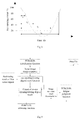
- the eye opening/closing detection module detects the eye closure rating of the driver using the PERCLOS algorithm.
- PERCLOS is short for percentage of eye closure, and refers to the proportion of the time when the eyes are closing within a certain period.
- three measuring manners namely, P70, P80, and EM are available, in which it is deemed that P80 can reflect the person's fatigue degree to the largest extent.
- FIG. 8 is a diagram of a principle for measuring a PERCLOS value.
- the curve indicates the change of opening/closing degree of eyes in one closing and opening procedure of eyes, and the lasting time of a certain closing or opening degree of eyes to be measured can be obtained according to this curve, thereby computing a PERCLOS value.
- t 1 is time from complete eye opening to 20% of eye closing
- t 2 is time from complete eye opening to 80% of eye closing
- t 3 is time from complete eye opening to 20% of eye opening next time
- t 4 is time from complete eye opening to 80% of eye opening next time.
- the PERCLOS value f can be obtained through measuring values from t 1 to t 4 .
- f is a percent of eye closing time to a certain period. For the P80 measuring manner, it can be deemed that when f>0.15, the driver is in a fatigue state.
- the working mode of the eye opening/closing detection module is shown in FIG. 9 .
- positions of the five sense organs of a face can be obtained.
- an eye opening/closing degree main function is invoked, and in combination with a positioning result of the five sense organs, an eye opening/closing degree value can be obtained.
- Image sequence results of data of multiple frames of images are accumulated, and in combination with the eye opening/closing degree value of the multiple frames of images, a judgment result indicating whether the driver is fatigue can be obtained.
- FIG. 10 shows a working mode of a yawning detection module.
- positions of the five sense organs of the face can be obtained.
- positions of the five sense organs of a face are obtained, for each frame of image, a mouth opening/closing judgment main function is invoked, and in combination with a positioning result of the five sense organs, a mouth opening/closing situation can be obtained.
- the mouth opening time is computed with reference to multiple frames of images, and a judgment result indicating whether the driver is fatigue can be obtained.
- FIG. 11 shows a working mode of a head movement tracking module. After data of an input single frame image is processed through the face detection module and the face feature point positioning module, positions of the five sense organs of the face can be obtained. After positions of the five sense organs of a face are obtained, a head position in each frame of image is separately computed, and in combination with a positioning result of the five sense organs, a head movement track can be obtained. The nodding frequency is computed with reference to multiple frames of images, and a judgment result indicating whether the driver is fatigue can be obtained.
- the comprehensive judgment module performs a weighting operation on detection results obtained by the eye opening/closing detection module, the yawning detection module and the head movement tracking module. Based on comprehensive judgment on three types of fatigue feature monitoring on the eye opening/closing state, the yawning state, and the head movement state, the driver fatigue degree is divided into four ranks: green color—not fatigue, yellow color—slight fatigue, orange color—intermediate fatigue, and red color—high fatigue.
- the detection result output by the comprehensive evaluation module is sobriety.
- the normal running of the vehicle is allowed, and a fatigue degree indicator lamp on the vehicle-mounted embedded device screen shows a green color.
- the detection result of the comprehensive evaluation module is slight fatigue.
- the normal running of the vehicle is allowed.
- a fatigue degree indicator lamp on the acousto-optic generator shows a continuously flickering yellow color, and the acousto-optic generator sends a warning sound to the driver.
- the detection result of the comprehensive evaluation module is intermediate fatigue.
- the fatigue degree indicator lamp on the acousto-optic generator shows a continuously flickering orange color, and meanwhile the acousto-optic generator sends a warning sound to the driver, the remote server and the preset client, to suggest that the driver should pull over.
- the detection result of the comprehensive evaluation module is high fatigue.
- the fatigue degree indicator lamp on the acousto-optic generator shows a continuously flickering red color
- an alarm lamp is automatically turned on to caution ambient vehicles and pedestrians
- the vehicle automatically decelerates and the engine goes off in several seconds
- the acousto-optic generator continuously sends an alarm to the remote server and the preset client and reports the position of the vehicle, to ask for help.
- the driver fatigue degree reaches the red color rank
- t dr t re (1 +k alcoholicity — re )(1 +k tiredness — re )+ t ex ⁇ (1 +k alcoholicity — ex )(1 +k tiredness — ex ) (4)
- the vehicle condition detection refers to detection on performance parameters of a vehicle, and computation of influence degrees of the performance parameters on crash avoidance manipulation time.
- the vehicle condition detection unit 2 is specifically divided into five underlying detection modules: vehicle basic parameter detection 21 , vehicle dynamic parameter detection 22 , gear position setting parameter detection 23 , deceleration and braking parameter detection 24 , and acceleration and starting parameter detection 25 .
- the vehicle basic parameter detection 21 includes the type, the size, and the no-load weight of a vehicle, which are generally set through entry in advance. With reference to the regional classification standard, the vehicles are classified into large-sized coach A1, tractor A2, city bus A3, medium-sized coach B1, large-sized wagon B2, small-sized manual transmission vehicle C1, small-sized automatic transmission vehicle C2, small-sized wagon C3, three-wheeled vehicle C4, and so on.
- the vehicle size (turning radius) is described through a three-dimensional envelope relative to a mounting position of the electronic terminal for implementing the present invention.
- the vehicle no-load weight is recorded as m 0 kilograms.
- the vehicle dynamic parameter detection 22 mainly includes a load weight m p , a current vehicle velocity v car , tire aging and tire pressure change, and so on.
- the load weight m p can be obtained through a load weight detection apparatus, and can also be preset before the vehicle is started.
- the current vehicle velocity v car can be obtained through satellite positioning data or a vehicle-mounted CAN bus.
- Automotive vehicles require regular maintenance and repair, and the tire pressure is adjusted to a regulated standard. However, during actual use, several tires wear out and age by different degrees, and performing abnormal pressure, thereby influencing vehicle manipulation performance.
- the vehicle running acceleration is expressed as follows:
- k aging is the tire aging and tire pressure abnormality influencing coefficient
- f is an acting force applied to the tires by a driving force or braking force with which the accelerator drives the engine (f is negative in the case of braking force)
- f resistance is a rolling resistance applied to the tires in contact with the ground, and is in a proportion to the total bearing weight
- the low tire pressure increases the rolling resistance, and the tire is deformed due to the movement, continuously causing energy loss, which approximately accounts for 90% to 95% of all the rolling resistance of the tire. If the tire air pressure is excessively high, the road holding force decreases, and the tire attrition accelerates. Under a non-standard tire pressure, the positive and negative deviation of the influence on the acceleration performance reaches 2% to 5%, and the positive and negative deviation of the influence on the braking performance reaches 5% to 10%. For this reason, a redundancy reliability monitoring apparatus for an internal working condition of a vehicle tire is specially disposed in the intelligent traffic safety system.
- FIG. 12 is a schematic diagram of a formation principle of the redundancy reliability monitoring apparatus.
- the redundancy reliability monitoring apparatus includes a vehicle upper module and a plurality of tire lower modules, in which the vehicle upper module is mounted inside a vehicle, and is formed of a reliable starting unit, a multi-channel warning unit and an emergency processing unit; the tire lower module is mounted inside each vehicle tire, and is formed of a redundancy measurement unit and an on-site processing unit.
- Each tire lower module and the vehicle upper module communicate with each other in a wireless manner.
- the reliable starting unit has a vehicle-mounted information interface
- the multi-channel warning unit has a remote network interface
- the emergency processing unit has a vehicle-mounted drive interface.
- the redundancy reliability monitoring apparatus has a notable feature, that is, various sensors are disposed in the redundancy measurement unit, and are respectively used for implementing pressure measurement, temperature measurement, humidity measurement, electricity measurement and movement induction inside a vehicle tire. These sensors adopt a redundancy configuration manner, namely, one primary sensor and at least one backup sensor are set for the same measurement objective, and each sensor separately sends a measurement signal independently. Furthermore, the wireless communication interface between the tire lower module and the vehicle upper module also adopts a similar redundancy configuration manner. In this way, it can be ensured that when the primary sensor or wireless communication interface is invalid, correct information about the working condition state inside the vehicle tire can still be obtained.
- the foregoing redundancy measurement unit is connected to the on-site processing unit.
- the on-site processing unit uses an embedded microprocessor in the tire lower module to perform on-site processing, including information collection, analysis and judgment, data uploading, shielding and switching, dormancy or wakeup.
- the information collection refers to collection of information such as movement induction, pressure measurement, temperature measurement, humidity measurement, and electricity quantity measurement.
- the analysis and judgment refer to analysis according to the collected measurement information and using the intrinsic mechanism of the on-site configuration solution, and judgment about whether dormancy or wakeup, data uploading, or shielding and switching should be performed.
- the function of the reliable starting unit in the vehicle upper module lies in that: when the vehicle upper module learns that the vehicle starts and operates smoothly and steadily from a vehicle-mounted information interface such as a vehicle CAN bus or GPS receiver, but does not obtain uploaded data of a certain tire lower module, the reliable starting unit sends a command to the tire lower module to require uploading of data, or require active/standby switch of the movement induction sensor; otherwise, the communication interface is switched.
- a vehicle-mounted information interface such as a vehicle CAN bus or GPS receiver
- the multi-channel warning unit in the vehicle upper module has an LED display and caution sound warning in the prior art, and also adopts particular preset voice warning (which can be “slow air leakage of the front right tire” in Chinese, or in other languages or dialects; the voice warning has default presetting and can be set through recording), including performing remote warning through a wireless network.
- the emergency processing unit in the vehicle upper module learns information relevant to driver capability decrease (such as the alcoholic strength: “slight drinking” or fatigue degree: “yellow color” warning) based on the vehicle-mounted information interface, and can automatically manipulate the vehicle to decelerate, pull over and brake through the vehicle-mounted drive interface.
- information relevant to driver capability decrease such as the alcoholic strength: “slight drinking” or fatigue degree: “yellow color” warning
- the redundancy reliability monitoring apparatus should be dormant, and is not waken up to work until the vehicle starts and the tires rotate. For this reason, the movement induction sensor detects rotation and motionless situations of a tire, and the embedded microprocessor in the tire lower module decides whether the redundancy reliability monitoring apparatus should be waken up to work or remain dormant according to a detection result.
- the tire lower module should continuously send data of the current tire condition to the vehicle upper module.
- the primary sensor in work is completely normal, it is judged whether the tire condition is normal according to the measurement information. If the primary sensor is abnormal, whether the abnormality matters further needs to be determined.
- the electricity consumed by the uploading communication accounts for an overwhelming majority, so if the abnormality matters, communication warning should be frequently uploaded; if the abnormality does not matter, warning is performed in an intermediate frequency; if primary sensor is normal, warning is performed in a sparse frequency. For example, the excessively high temperature that easily leads to tire burst matters very much, and rapid air leakage of a tire also matters very much.
- the most preferable value of the internal pressure of a certain vehicle tire is 2.5 atmospheric pressure, as shown in FIG. 13 .
- the tire pressure is greater than 2.0 atmospheric pressure, tires still enable the whole vehicle to run, but if the tire pressure is lower than 2.0 atmospheric pressure and continues to decrease, the tire rolling resistance apparently increases.
- the embedded microprocessor in the tire lower module can judge whether the tire pressure is abnormal, and whether it is slow air leakage or rapid air leakage according to a relationship between the tire rolling resistance and the tire pressure shown in FIG. 13 .
- the embedded microprocessor in the tire lower module can independently determine that the primary sensor is invalid.
- the vehicle upper module knows that the vehicle has started and run through the vehicle-mounted information interface, but the tire lower module does not upload relevant data, it is possible that the primary movement induction sensor is abnormal.
- tire pressure abnormality is found during regular maintenance, and no warning is obtained during the recent running, it is also possible that the primary pressure sensor is invalid.
- the embedded microprocessor in the tire lower module When finding out that the primary sensor is abnormal, the embedded microprocessor in the tire lower module independently shields the detection interface, and obtaining of the measurement data is automatically switched to the backup sensor interface. If primary sensor abnormality is found in another manner, the vehicle upper module sends a command to the tire lower module, the tire lower module shields the corresponding detection interface after receiving the command, and obtaining of the measurement data is automatically switched to the backup sensor interface.
- the gear position setting parameter detection 23 is recorded as l speed (v car ), and can be preset according to a rated value of the current vehicle, for example: the speed of the first rank is below 20 kilometers per hour, the speed of the second rank is 20 kilometers to 40 kilometers per hour, the speed of the third rank is 40 kilometers to 60 kilometers per hour, the speed of the fourth rank is 60 kilometers to 80 kilometers per hour, and the speed of the fifth rank is more than 80 kilometers per hour.
- the vehicle braking capability can be indicated by the distance d 100 for which the vehicle moves during the deceleration from the speed of 100 kilometers per hour to the speed of zero, and an average maximum acceleration corresponding thereto is expressed as follows:
- a brake , 0 ( 100000 / 3600 ) 2 2 ⁇ ⁇ d v ⁇ ⁇ 100 ⁇ 385.8 d v ⁇ ⁇ 100 ⁇ ( m ⁇ / ⁇ s 2 ) ( 7 )
- a brake m 0 m 0 + m p ⁇ a brake , 0 ( 8 )
- the vehicle starting capability can be indicated by the time t v100 required for acceleration from the speed of zero to the speed of 100 kilometers per hour, and an average maximum acceleration corresponding thereto is expressed as follows:
- a gun , 0 100000 / 3600 t v ⁇ ⁇ 100 ⁇ 27.8 t v ⁇ ⁇ 100 ⁇ ( m ⁇ / ⁇ s 2 ) ( 9 )
- a gun m 0 m 0 + m p ⁇ a gun , 0 ( 10 )
- the road condition detection refers to detection on the inherent performance, the dynamic condition and the environment situation of the current road, and computation of influencing degrees of the inherent performance, the dynamic condition and the environment situation on crash avoidance manipulation time.
- the road condition detection unit 3 is specifically divided into six underlying detection modules: road basic parameter detection 31 , weather influencing factor detection 32 , road busy degree detection 33 , front barrier detection 34 , rear pursuer detection 35 , and opposite pursuer detection 36 .
- the content of the road basic parameter detection 31 includes one-way lane, bidirectional lane, isolation, the number of vehicle lanes, evenness, camber and gradient, most of which can be obtained through a commercial navigation product based on positioning and a digital map currently.
- the bidirectional lane shown in FIG. 14 when the middle bold black line only represents physical isolation implementation, the bidirectional lane is an isolation road.
- a curvature radius is expressed as follows:
- ⁇ r (*, ⁇ B ⁇ A , ⁇ C ⁇ B , ⁇ D ⁇ C , ⁇ E ⁇ D , ⁇ F ⁇ E , ⁇ G ⁇ F ) T (14)
- the active anti-crash apparatus inside the vehicle can take corresponding technical measures in advance, such as automatic deceleration, and warning in advance.
- the similar method can be used for pre-estimating the gradient of the front road, and in this case, the foregoing longitude/latitude parameter is changed to an altitude parameter.
- polynomial fitting can be performed on the change of the altitude of the front road along with the arc length, and simpler approximate computing can also be performed using a trigonometric function. For example, for points B, D, and F in FIG. 15 , the following formula can be obtained:
- ⁇ B arctan ⁇ ( h C - h A 2 ⁇ ⁇ ⁇ ⁇ s )
- ⁇ D arctan ⁇ ( h E - h C 2 ⁇ ⁇ ⁇ ⁇ s )
- ⁇ F arctan ⁇ ( h G - h E 2 ⁇ ⁇ ⁇ ⁇ s ) ( 15 )
- gradients of the front road are classified into 5 ranks according to the magnitude thereof: abrupt downward slope, gentle downward slope, no slope, gentle upward slope, and abrupt upward slope.
- the active anti-crash apparatus inside the vehicle can take corresponding technical measures in advance, such as accelerating, and braking by use of the engine.
- the weather influencing factor detection 32 includes detection on fog, rain, ice, snow and so on, and generally may be obtained through communication between the vehicle-mounted information system and the traffic network facility.
- ⁇ 0 in formula (6) the value is 0.77 on an ordinary road surface, the value is 0.9 on a slip-resistant road surface, and the value is 0.64 on a slip-apt road surface; an abnormal weather causes an unpredictable severe influence on the road surface.
- the result of the road busy degree detection 33 may also be obtained through communication between the vehicle-mounted information system and the traffic network facility. According to the extent, the road busy degrees can be classified into four ranks: severe jam (average speed ⁇ 20 kilometers per hour), slight jam (20 kilometers per hour ⁇ average speed ⁇ 0.6 time of the speed limit), unblocked (0.6 time of the speed limit ⁇ average speed ⁇ 1.2 times of the speed limit), and sparse vehicle flow (average vehicle flow ⁇ one vehicle per minute).
- the front barrier detection 34 can detect dynamic change situations of the relative direction, the distance and the speed of a target using a vehicle active anti-crash module based on a microwave radar. When it is found through the detection result that the target is located in front of the current vehicle, and the movement direction thereof is close to that of the current vehicle, the target is a front barrier.
- FIG. 16 is an overall schematic structural diagram of a vehicle active anti-crash module based on a microwave radar.
- the vehicle active anti-crash module is formed of a transmitting/receiving front end and a signal processing rear end.
- the transmitting/receiving front end and the signal processing rear end are connected through a power line, a control line, an analog modulation signal line and an echo signal line.
- the control line is used for transmitting an enabling control signal for controlling working state switching of the transmitting/receiving front end.
- the analog modulation signal line is used for transmitting an analog modulation signal input from the signal processing rear end to the transmitting/receiving front end.
- the echo signal line is used for transmitting an echo signal from the transmitting/receiving front end to the signal processing rear end.
- the analog modulation signal line and the echo signal line are connected through a port cable of a coaxial-cable connector.
- the transmitting/receiving front end is formed of a micro-strip antenna array, a transmitting/receiving component and an interface circuit.
- the micro-strip antenna array is connected to the transmitting/receiving component, and the transmitting/receiving component is connected to the interface circuit.
- the micro-strip antenna array is used for receiving/transmitting a high-frequency carrier.
- the transmitting/receiving component mainly includes a VCO and a mixer, in which the VCO receives an analog modulation signal input from the interface circuit, and the mixer outputs an echo signal to the interface circuit.
- the interface circuit includes: a preamplifier, a matched filter, an AGC amplification circuit, a modulation signal filter and a power supply adjustment circuit.
- the preamplifier, the matched filter and the AGC amplification circuit are sequentially connected, and have the function of performing filtering and amplification processing on the echo signal.
- the modulation signal filter is connected between the signal processing rear end and the transmitting/receiving component, and has the function of performing filtering processing on an analog modulation signal generated by the signal processing rear end.
- the power supply adjustment circuit is also connected between the signal processing rear end and the transmitting/receiving component, and has the following functions: ⁇ circle around (1) ⁇ a voltage stabilization function: stabilizing the voltage supplied to the transmitting/receiving front end 1, so as to enable the transmitting/receiving front end to work normally; and ⁇ circle around (22) ⁇ voltage adjustment: responding to an enabling control input of the signal processing rear end, and adjusting the voltage to generate an adjustable voltage of ⁇ 5V, 0, and +5V, so as to control the working state of the transmitting/receiving front end through the adjustable voltage.
- the internal structure of the signal processing rear end is shown in FIG. 19 .
- the signal processing rear end is formed of an analog-to-digital conversion module, an FPGA, a digital signal processing chip, a digital-to-analog conversion module, a display warning circuit, a vehicle bus expanding module and a power supply module.
- the analog-to-digital conversion module receives an analog signal of the interface circuit through an echo signal line, and inputs a digital signal obtained through conversion to the FPGA.
- the digital-to-analog conversion module 16 receives a digital modulation signal from the FPGA, performs digital-to-analog conversion on the digital modulation signal, and outputs the signal to the interface circuit through an analog modulation signal line.
- the FPGA has the following functions: ⁇ circle around (1) ⁇ receiving a control signal input of a digital signal processing chip, so as to judge whether to start analog-to-digital conversion and when to start, and when to stop; ⁇ circle around (2) ⁇ performing software filtering on the data obtained through conversion of the analog-to-digital conversion module and storing the data obtained after filtering; ⁇ circle around (3) ⁇ generating a digital modulation signal, and controlling the digital-to-analog conversion module to perform digital-to-analog conversion on the digital modulation signal; and ⁇ circle around (4) ⁇ sending a control signal through the control line, and controlling the working state of the transmitting/receiving front end.
- the FPGA is connected to the digital signal processing chip.
- the digital signal processing chip receives external input signals about the road condition, the vehicle condition and the person condition.
- the digital signal processing chip is connected to the display warning circuit in an aspect, and accesses the vehicle bus through the vehicle bus expanding module in another aspect. Its main functions are as follows: ⁇ circle around (1) ⁇ performing mathematical operation processing on a signal conversion result of the analog-to-digital conversion module stored in the FPGA, and extracting speed and distance information of the target from the signal conversion result; ⁇ circle around (2) ⁇ inputting the speed and distance information of the target to the display warning circuit for acousto-optic display warning; ⁇ circle around (3) ⁇ sending a control instruction to the FPGA, so as to decide whether to start the analog-to-digital conversion, when to start, and when to stop.
- the function of the display warning circuit lies in performing sound or display warning on the speed and distance information input by the digital signal processing chip.
- the function of the vehicle bus expanding module lies in converting a serial bus of the digital signal processing chip into a vehicle bus adopting the CAN and 485 standards.
- the function of the power supply module lies in providing multiple voltage ranks to supply power to the entire vehicle active anti-crash module.
- the digital signal processing chip uses a TMS320C6713 processor of TI Corporation, performs Fast Fourier Transform (FFT) processing on a collected and converted signal, and extracts distance and speed information of the corresponding target.
- FFT Fast Fourier Transform
- a two-hundred-thousand-gate SPARTAN FPGA is selected for corresponding storage, AD control, modulation wave generation, software filtering, and enabling control output programming.
- An AD9240 analog-to-digital conversion module with double channels, 14 bits, and a sampling rate of 10M is selected.
- the entire system uses a 12V power source, and performs corresponding voltage stabilization and level conversion to supply power to the corresponding chip and circuit.
- level conversion is performed in the interface circuit of the transmitting/receiving front end, so as to output a positive level, a negative level, and a zero level.
- the display warning circuit uses an ARM9 processor, an LCD display screen and a microphone, and the ARM9 processor receives the output of the speed and distance information of TMS320C6713.
- the FPGA sends a digital modulation signal, and the digital modulation signal is converted into an analog modulation signal-triangular wave/sawtooth wave through the digital-to-analog conversion module.
- the analog modulation signal is transmitted to the modulation signal filter in the interface circuit through the analog modulation signal line. Noise is removed through filtering processing, and the analog modulation signal with the noise removed is then transmitted to the VCO of the transmitting/receiving component.
- a high-frequency carrier is generated, and this high-frequency carrier is sent out through the micro-strip antenna array. After being sent out through the micro-strip antenna array, the high-frequency carrier is reflected back when encountering a barrier, is received through the micro-strip antenna array, and is transmitted to the transmitting/receiving component.
- the high-frequency carrier is processed by the transmitting/receiving component, output by the mixer to the interface circuit, then processed sequentially processed by the preamplifier, the matched filter, and the AGC amplification circuit, and is transmitted to the signal processing rear end through the echo signal line.
- the signal reflected back is transmitted to the analog-to-digital conversion module.
- an analog signal is converted into a digital signal, and the data obtained through conversion is transmitted to the FPGA in real time for software filtering, and the data after filtering is stored.
- the analog-to-digital conversion module completes a sampling conversion procedure, the FPGA feeds the stored data into the digital signal processing chip for mathematical operation processing, and capture distance and relative speed information of the target barrier from the data.
- the digital signal processing chip transmits the distance and speed information to the display warning circuit.
- the display warning circuit generates, according to the distance and the speed of the target barrier relative to the current vehicle, a sound or display alarm for the driver, to remind the driver to decelerate or brake.
- the digital signal processing chip converts a serial signal into a signal conforming to the CAN or 485 standard through the vehicle bus expanding module, so as to be conveniently connected to another device inside the vehicle using the CAN or 485 standard, and transfer the distance information, the speed information, and the warning information or perform relevant control output according to the distance and speed information.
- the microwave radar captures vehicle condition information through the vehicle bus expanding module.
- the vehicle condition information is combined with road condition information and person condition information (detection results on front, rear, left, and right barriers obtained by the microwave radar belong to the road condition information), and comprehensive computing is performed, so as to provide the driver with operation suggestions, such as deceleration, braking, and steering.
- the operation of the driver is captured and judged through the vehicle bus.
- a reminder is provided again and a control instruction is sent to the vehicle bus, to instruct the vehicle to take non-artificial risk avoidance measures such as safety air bag opening, mandatory braking, and mandatory deceleration.
- the rear pursuer detection 35 can be implemented using the foregoing vehicle active anti-crash module based on a microwave radar. When it is found through a detection result that the target is located behind the current vehicle, and the movement direction thereof is close to that of the current vehicle, the target is a rear pursuer.
- the opposite pursuer detection 36 can be implemented using the foregoing vehicle active anti-crash module based on a microwave radar. When it is found through the detection result that the target is located in front of the current vehicle, the movement direction thereof is opposite to that of the current vehicle, and the road is not isolated, the target is an opposite pursuer.
- the relative distance measurement value is recorded as r mea . It is assumed that the maximum value and the minimum value of the possible measurement error of the relative distance are respectively e rmax (r mea ), e rmin (r mea ).
- the relative distance reference value r relative [r mea ⁇ e rmin (r mea ),r mea +e rmax (r mea )].
- the relative speed measurement value is recorded as v mea .
- a direct crash between current vehicle and the target may occur.
- k crooked 3.0, 1.5, 1.0 correspondingly
- k gradient 3.0, 1.5, 1.0 correspondingly.
- a target with a greater threat should be avoided in priority.
- the driver warning unit 5 in the intelligent traffic safety system gives a multimedia augmented reality alarm to the driver through combining a graphical interface and voice, so that the driver intuitionally feels the surrounding anti-crash safety environment.
- the warning is classified into the acceleration/deceleration yellow warning, the acceleration/deceleration red warning, and the steering and lane changing operation prompt.
- the yellow warning is defined on the basis of the assumption that a crash may occur if no manipulation measure is taken.
- formula (17) is multiplied by a weighting coefficient n yellow namely, when t relative ⁇ n yellow t dr (20)
- an acceleration or braking yellow warning is sent to the driver of the current vehicle.
- a braking warning is sent; to avoid a passive rear-end collision, an acceleration warning is sent; to avoid front and rear targets at the same time, a steering and lane changing prompt is sent.
- red warning is defined on the basis of the assumption that a crash may occur even if the vehicle acceleration/deceleration ultimate capability is brought into play.
- formula (18) is multiplied by a weighting coefficient n red , namely, when a relative >n red a brake (21)
- an acceleration or braking red warning is sent to the driver of the current vehicle.
- a braking warning is sent; to avoid a passive rear-end collision, an acceleration warning is sent; to avoid front and rear targets at the same time, a steering and lane changing prompt is sent.
- the current vehicle mandatory processing unit 6 mandatorily performs acceleration, deceleration, and steering and lane changing processing.
- the barrier warning unit 7 sends a voice alarm to the front target vehicle or the pedestrian through a loudspeaker.
- the pursuer warning unit 8 sends a voice alarm to the rear or opposite approaching vehicle through a loudspeaker.
- the after-crash warning unit 9 transmits the geographic position, the accident condition and the on-site video recorded by the vehicle-mounted positioning device to the remote monitoring terminal using the wireless communication network.
- the intelligent traffic safety system provided in the present invention can be implemented based on technical supporting means such as a cloud computing platform and a wireless network (including a wireless local area network and a wide area wireless network).
- a cloud computing platform and a wireless network including a wireless local area network and a wide area wireless network.
- the intelligent traffic safety system can implement information exchange among three major essential factors: vehicle, person, and facility.
- the information exchanged between the cloud computing platform and each vehicle-mounted electronic terminal includes road condition information, vehicle condition information, and person condition information. Detailed illustration is provided below.
- the intelligent traffic safety system is formed of a server supporting cloud computing, several vehicle-mounted electronic terminals (or other mobile terminals) mounted on vehicles and a cloud monitoring terminal mounted on a traffic infrastructure.
- the cloud computing platform is formed of a cloud computing server and a cloud monitoring terminal, and provides elementary computing for the entire intelligent traffic safety system, provides a management function, and provides functions of statistics, storage, sharing, and issuing of massive data.
- the cloud computing platform is connected to each vehicle-mounted electronic terminal through a wide area wireless network and/or cable network, and the vehicle-mounted electronic terminals are connected with each other through a wireless network.
- Cloud computing servers can be deployed in public security departments of administrative regions such as a province, a city, a town, and a district. These servers form a distributed server cluster, each level of servers is networked with a database of a superior or peer public security department. Sharing and transfer of data information about traffic safety and security are performed in the cluster, and management levels and rights as well as liabilities are classified into different ranks.
- the cloud computing server allocates the supervision management authority to the cloud monitoring terminal.
- the command center where the cloud computing server is located can perform person condition information examination on any vehicle in an administrative area thereof, collect and store detection results and information, and perform corresponding warning and policemen dispatching actions through the cloud monitoring terminal.
- the cloud monitoring terminal has the following functions: (1) after being authorized by the cloud computing server, connecting with a vehicle-mounted electronic terminal through a wide area wireless network, exchanging video, sound and control signals with the vehicle-mounted electronic terminal, and actively examining and collecting the person condition information of the vehicle-mounted electronic terminal; (2) receiving warning information of the vehicle-mounted electronic terminal; and (3) exchanging data information resources with the cloud computing server.
- the cloud monitoring terminal can be classified into the following two types:
- This type of monitoring terminal is deployed at fixed sites such as a “traffic infrastructure” and a “security management infrastructure”. Positions of these infrastructures ensure grassroot-oriented traffic management and security management, for example, traffic management and security management in parking lot, traffic toll gate, traffic flow indication plate, security police box, and community committee.
- These monitoring terminals are authorized by the cloud computing server, and are mainly responsible for collecting or forwarding information about the road condition, the vehicle condition, and the person condition, or exerting a supervision management function on traffic and security in the administrative area thereof.
- this type of monitoring terminal is deployed at a police vehicle and a police motorcycle in the public security system. Through these vehicle-mounted monitoring terminals, public security policemen can perform mobile on-site person condition information examination on automotive vehicles on the road and feed back the information to the cloud computing server in time.
- a vehicle-mounted electronic terminal has a person condition detection unit, and relative to the cloud monitoring terminal, the vehicle-mounted electronic terminal is in a status of being examined and supervised. That is, when a certain cloud monitoring terminal actively sends a person condition examination request, the vehicle-mounted electronic terminals respond passively and accept the examination. Meanwhile, when the vehicle-mounted electronic terminal performs non-networking local person condition information detection, and finds a dangerous case, the vehicle-mounted electronic terminal can actively send a warning signal to the cloud monitoring terminal to ask for help.
- the cloud computing platform is provided with functions of collecting, storing, computing, transmitting and managing data of the vehicle-mounted electronic terminal, and can provide good network access and safety guarantee capabilities, thereby effectively overcoming disadvantages of the vehicle-mounted electronic terminal such as small storage capacity and weak computing capability.
- the cloud computing platform can collect the video information of the vehicle driver through the vehicle-mounted electronic terminal, extract facial features, and perform computing through a fatigue driving algorithm, so as to judge whether the driver is in a fatigue driving state and determine the fatigue degree of the driver, to judge whether the driver is threatened and hijacked by a criminal, and to judge whether the vehicle is driven, burglarized or robbed by a criminal; according to the safety hazard information about person condition, vehicle condition and road condition which uploaded by vehicle-mounted electronic terminal, judging and learning, mechanism analysis and database updating, for example, updating the gradient information and the camber information; providing safety path warning, providing the safety hazard information about person condition, vehicle condition and road condition to vehicle-mounted electronic terminal on road in advance, or attaching a safety alert layer on the digital map online for the vehicle-mounted electronic terminal with navigation function on road.
- each vehicle-mounted electronic terminal is a cloud computing terminal, and the server is the cloud computing platform.
- the vehicle-mounted electronic terminal accesses the cloud computing platform through the wireless network.
- Each vehicle-mounted electronic terminal has a unique ID number; the user name and the password are designated by the user at the first time of access, and are used for verification during subsequent login.
- accessibility verification needs to be performed, and procedure is as follows:
- the vehicle-mounted electronic terminal sends the pre-designated personal login user name, password, and terminal ID to the cloud computing platform in the encoding form of “user name+password+ID”.
- the cloud computing platform performs retrieval in the database, and establishes a network connection after determining that the user and the vehicle-mounted electronic terminal exist; otherwise, the access is denied.
- the cloud computing platform opens an independent storage space for each vehicle-mounted electronic terminal, where vehicle information can be stored, and the vehicle information specifically includes: the user information of the vehicle-mounted electronic terminal, the device ID, the video files and pictures collected from the vehicle-mounted electronic terminal, the vehicle state and history information, the vehicle position, the fatigue driving warning information, the illegitimate driving warning information, and the alcohol test record collected by the vehicle-mounted electronic terminal through the CAN bus.
- FIG. 22 is a schematic diagram of distribution of a wireless network in a certain section of a highway.
- the wireless network integrates a local area network and a wide area network, and a vehicle and traffic infrastructures around the vehicle form a wireless local area network. When many vehicles are running, each vehicle may exist in multiple local area networks simultaneously.
- the networking of the wireless local area network is adaptive.
- the wireless local area network is constructed preferentially in the ZigBee manner.
- ZigBee is a technology for networking an internet of thinks, has the following characteristics:
- a network node can perceive other nodes, and form a network with the node.
- the network heals automatically, and correspondingly adjusts the network topology structure, so that the network can still work normally.
- a mesh type network namely, multi-point to multi-point network can be formed. Any two devices in the network can exchange data.
- the ZigBee network supports the AES128 encryption algorithm.
- a ZigBee network can accommodate at most 254 slave devices and one master device, and at most more than 200 ZigBee networks can co-exist in the same region.
- the function of the wireless local area network formed of vehicle-mounted electronic terminals mainly lies in reminding an adjacent vehicle of safety.
- a vehicle-mounted electronic terminal mounted on a certain vehicle sends a data packet indicating a condition of the vehicle through the wireless network, and after receiving the data packet, another vehicle-mounted electronic terminal mounted on a nearby vehicle takes necessary countermeasures according to content of the data packet.
- a vehicle incurs or finds an urgency situation or needs to perform a certain vehicle operation, in order to avoid affecting another vehicle, another vehicle needs to be informed of the state of the current vehicle or the operation to be performed by the current vehicle in advance.
- the vehicle-mounted electronic terminal on the vehicle sends data information to another vehicle.
- the vehicle-mounted electronic terminal when it is detected that a driver in a vehicle is in a danger state of drunk driving, fatigue driving, or being hijacked, the vehicle-mounted electronic terminal also sends a signal to a vehicle nearby and the server, so as to give an alarm or ask for help. Because the number of vehicles is enormous on the road, each vehicle may exist in multiple local area networks simultaneously, and when a vehicle receives alarm information or information for help from a local area network, the vehicle transmits the information to vehicles in other local area networks.
- the networking of the local area network is determined according to the relative position and the vehicle running direction computed based on the absolute position of the vehicle measured by a built-in navigation positioning module of the vehicle-mounted electronic terminal.
- the distance of the vehicle relative to an ambient vehicle can be indirectly obtained according to the measurement data of navigation positioning modules of multiple vehicle-mounted electronic terminals, thereby calculate the running direction.
- local area network communication is established only between vehicles whose running directions are the same and whose inter-vehicle straight-line distance is within 300 meters. For traffic infrastructures, local area network communication is also established only when the distance to the vehicle is less than 300 meters.
- Each data packet sent from a vehicle-mounted electronic terminal on a vehicle is encoded according to different situations, the structure of “data header+terminal device ID+license plate number+states+verification bit+parking bit” can be adopted, and the states indicate five states, which specifically include: fatigue driving, drunk driving, hijacked, overtaking request, and parking request.
- the states are specifically indicated with a digit:
- State 5 parking request: 00 (no request), and 01 (parking request).
- state 1 to state 5 are sequentially encoded, and different digits are used to indicate respective corresponding states.
- a vehicle-mounted electronic terminal on another vehicle can distinguish states of the current vehicle and the driver through the data packet, so as to take necessary countermeasures.
- a ZigBee network formed of different vehicles can obtain relative positions and relative speeds of the vehicles, and send caution information in the case of parking, overtaking, and circumambulating operations so as to avoid a crash.
- This intelligent traffic safety mode is hardly influenced by the weather and the landform, and can also normally work in an extreme weather condition such as fog, rain and snow.
Landscapes
- Engineering & Computer Science (AREA)
- Transportation (AREA)
- Mechanical Engineering (AREA)
- Automation & Control Theory (AREA)
- Chemical & Material Sciences (AREA)
- Combustion & Propulsion (AREA)
- Physics & Mathematics (AREA)
- Mathematical Physics (AREA)
- Traffic Control Systems (AREA)
Abstract
Description
t relative >t dr
t dr0 =t re +t ex =t re0 +t ex− (1)
t dr =t re(1+k alcoholicity
t dr =t re(1+k tiredness
t dr =t re(1+k alcoholicity
μ=μ0 −kv car (6)
is determined according to the length lcar of the vehicle and a road jam degree djam, multiple points are selected according to an interval Δs between two adjacent points in the front and back of the road, for example, two points A, B behind the vehicle are selected, four points D, E, F, G in front of the vehicle are selected, a coordinate value of each point in the dynamic azimuth coordinate system is obtained according to the longitude/latitude of each of the points A, B, C, D, E, F, G and the values are recorded as two column vectors:
X r=(x A ,x B ,x c ,x D ,x E ,x F ,x G)T ,Y r=(y A ,y B ,y c ,y D ,y E ,y F ,y G)T.
y=a 0 +a 1 x+a 2 x 2 +a 3 x 3 ,{dot over (y)}=a 1+2a 2 x+3a 3 x 2 ,ÿ=2a 2+6a 3 x
ψr=(*,ψB−ψA,ψC−ψB,ψD−ψC,ψE−ψD,ψF−ψE,ψG−ψF)T (14)
t relative >t dr (17)
t relative <n yellow t dr (20)
a relative >n red a brake (21)
β≈ arcsin(L/R),ψsw=8nβ. (22)
Claims (19)
t dr =t re(1+k alcoholicity
y=a 0 +a 1 x+a 2 x 2 +a 3 x 3 ,{dot over (y)}=a 1+2a 2 x+3a 3 x 2 ,ÿ=2a 2+6a 3 x
Applications Claiming Priority (22)
| Application Number | Priority Date | Filing Date | Title |
|---|---|---|---|
| CN201020187696 | 2010-05-12 | ||
| CN201020187696.0 | 2010-05-12 | ||
| CN2010201876960U CN201761368U (en) | 2010-05-12 | 2010-05-12 | Remote wireless monitoring system for alcoholic content of drivers |
| CN201010620675 | 2010-12-31 | ||
| CN201010620675.8 | 2010-12-31 | ||
| CN201020696640 | 2010-12-31 | ||
| CN201020696275.0 | 2010-12-31 | ||
| CN2010206966408U CN201932117U (en) | 2010-12-31 | 2010-12-31 | Network system for preventing automobile burglaries and robberies based on pattern recognition |
| CN201010620675.8A CN102097003B (en) | 2010-12-31 | 2010-12-31 | Intelligent traffic safety system and terminal |
| CN201020696275 | 2010-12-31 | ||
| CN201020696275 | 2010-12-31 | ||
| CN201020696640.8 | 2010-12-31 | ||
| CN201120149271.5 | 2011-05-11 | ||
| CN201120149259 | 2011-05-11 | ||
| CN201120149271 | 2011-05-11 | ||
| CN2011201492594U CN202029653U (en) | 2011-05-11 | 2011-05-11 | Monitoring system for redundancy reliability of internal condition of automobile tire |
| CN2011201492715U CN202029843U (en) | 2011-05-11 | 2011-05-11 | Vehicle active anti-collision system based on microwave radar |
| CN201120149259.4 | 2011-05-11 | ||
| CN201110122062 | 2011-05-12 | ||
| PCT/CN2011/074013 WO2011140993A1 (en) | 2010-05-12 | 2011-05-12 | Intelligent traffic safety system based on comprehensive state detection and decision method thereof |
| CN201110122062.6 | 2011-05-12 | ||
| CN201110122062.6A CN102201035B (en) | 2011-05-12 | 2011-05-12 | A kind of predictor method calculating road ahead camber/gradient |
Related Parent Applications (1)
| Application Number | Title | Priority Date | Filing Date |
|---|---|---|---|
| PCT/CN2011/074013 Continuation WO2011140993A1 (en) | 2010-05-12 | 2011-05-12 | Intelligent traffic safety system based on comprehensive state detection and decision method thereof |
Publications (2)
| Publication Number | Publication Date |
|---|---|
| US20130069773A1 US20130069773A1 (en) | 2013-03-21 |
| US8841994B2 true US8841994B2 (en) | 2014-09-23 |
Family
ID=44913961
Family Applications (1)
| Application Number | Title | Priority Date | Filing Date |
|---|---|---|---|
| US13/674,836 Active US8841994B2 (en) | 2010-05-12 | 2012-11-12 | Intelligent traffic safety system based on comprehensive state detection and decision method thereof |
Country Status (2)
| Country | Link |
|---|---|
| US (1) | US8841994B2 (en) |
| WO (1) | WO2011140993A1 (en) |
Cited By (15)
| Publication number | Priority date | Publication date | Assignee | Title |
|---|---|---|---|---|
| US20160033297A1 (en) * | 2013-04-26 | 2016-02-04 | Mitsubishi Electric Corporation | In-vehicle device, information distribution server, and facility information display method |
| US9443426B1 (en) | 2015-11-13 | 2016-09-13 | Byron Paul Formwalt | Method and device for sensing traffic flow and notifying motor vehicle drivers of the same |
| US10150474B2 (en) | 2017-01-04 | 2018-12-11 | Robert Bosch Gmbh | Reducing lateral position deviation during an automated lane change |
| US10214220B2 (en) | 2016-09-30 | 2019-02-26 | International Business Machines Corporation | Intelligent driving recommendation system |
| US10220841B2 (en) * | 2015-10-22 | 2019-03-05 | Honda Research Institute Europe Gmbh | Method and system for assisting a driver of a vehicle in driving the vehicle, vehicle and computer program |
| US10670479B2 (en) | 2018-02-27 | 2020-06-02 | Methode Electronics, Inc. | Towing systems and methods using magnetic field sensing |
| US10696109B2 (en) | 2017-03-22 | 2020-06-30 | Methode Electronics Malta Ltd. | Magnetolastic based sensor assembly |
| US10901423B2 (en) | 2017-09-01 | 2021-01-26 | International Business Machines Corporation | Generating driving behavior models |
| US11014417B2 (en) | 2018-02-27 | 2021-05-25 | Methode Electronics, Inc. | Towing systems and methods using magnetic field sensing |
| US11084342B2 (en) | 2018-02-27 | 2021-08-10 | Methode Electronics, Inc. | Towing systems and methods using magnetic field sensing |
| US11135882B2 (en) | 2018-02-27 | 2021-10-05 | Methode Electronics, Inc. | Towing systems and methods using magnetic field sensing |
| US11221262B2 (en) | 2018-02-27 | 2022-01-11 | Methode Electronics, Inc. | Towing systems and methods using magnetic field sensing |
| US11491832B2 (en) | 2018-02-27 | 2022-11-08 | Methode Electronics, Inc. | Towing systems and methods using magnetic field sensing |
| US11615688B2 (en) | 2017-12-22 | 2023-03-28 | Resmed Sensor Technologies Limited | Apparatus, system, and method for motion sensing |
| US11707197B2 (en) | 2017-12-22 | 2023-07-25 | Resmed Sensor Technologies Limited | Apparatus, system, and method for physiological sensing in vehicles |
Families Citing this family (86)
| Publication number | Priority date | Publication date | Assignee | Title |
|---|---|---|---|---|
| EP2023812B1 (en) | 2006-05-19 | 2016-01-27 | The Queen's Medical Center | Motion tracking system for real time adaptive imaging and spectroscopy |
| WO2013032933A2 (en) | 2011-08-26 | 2013-03-07 | Kinecticor, Inc. | Methods, systems, and devices for intra-scan motion correction |
| CN103247091B (en) * | 2012-02-07 | 2016-01-20 | 厦门金龙联合汽车工业有限公司 | A kind of driving evaluation system and method |
| US8799032B2 (en) * | 2012-05-22 | 2014-08-05 | Hartford Fire Insurance Company | System and method to predict an insurance policy benefit associated with telematics data |
| US9341718B2 (en) * | 2012-09-07 | 2016-05-17 | Honeywell International Inc. | Method and system for providing integrity for hybrid attitude and true heading |
| US9305365B2 (en) | 2013-01-24 | 2016-04-05 | Kineticor, Inc. | Systems, devices, and methods for tracking moving targets |
| US9717461B2 (en) | 2013-01-24 | 2017-08-01 | Kineticor, Inc. | Systems, devices, and methods for tracking and compensating for patient motion during a medical imaging scan |
| US10327708B2 (en) | 2013-01-24 | 2019-06-25 | Kineticor, Inc. | Systems, devices, and methods for tracking and compensating for patient motion during a medical imaging scan |
| CN109008972A (en) | 2013-02-01 | 2018-12-18 | 凯内蒂科尔股份有限公司 | The motion tracking system of real-time adaptive motion compensation in biomedical imaging |
| US20140266739A1 (en) * | 2013-03-18 | 2014-09-18 | Digio2 International Co., Ltd. | Health monitoring and warning system |
| ITRM20130274A1 (en) * | 2013-05-08 | 2014-11-09 | Smart I S R L | DISTRIBUTED AND INTELLIGENT OPTICAL SENSOR SYSTEM FOR ADAPTIVE, PREDICTIVE AND ON-DEMAND CONTROL OF PUBLIC LIGHTING |
| CN104276082A (en) * | 2013-07-05 | 2015-01-14 | 鸿富锦精密工业(深圳)有限公司 | Vehicle-mounted auxiliary device |
| DE102013214383A1 (en) * | 2013-07-23 | 2015-01-29 | Robert Bosch Gmbh | Method and device for providing a collision signal with regard to a vehicle collision, method and device for managing collision data regarding vehicle collisions, and method and device for controlling at least one collision protection device of a vehicle |
| US9403482B2 (en) | 2013-11-22 | 2016-08-02 | At&T Intellectual Property I, L.P. | Enhanced view for connected cars |
| GB2521665A (en) * | 2013-12-30 | 2015-07-01 | Nokia Technologies Oy | Method, apparatus, computer program and system for controlling a vehicle's alert output |
| US9475387B2 (en) * | 2014-03-16 | 2016-10-25 | Roger Li-Chung Wu | Drunk driving prevention system and method with eye symptom detector |
| WO2015148391A1 (en) | 2014-03-24 | 2015-10-01 | Thomas Michael Ernst | Systems, methods, and devices for removing prospective motion correction from medical imaging scans |
| WO2015155847A1 (en) * | 2014-04-09 | 2015-10-15 | 株式会社 テクノミライ | Digital loss/accident defense system, method, and program |
| US9734589B2 (en) | 2014-07-23 | 2017-08-15 | Kineticor, Inc. | Systems, devices, and methods for tracking and compensating for patient motion during a medical imaging scan |
| JP5880740B1 (en) * | 2014-12-26 | 2016-03-09 | 横浜ゴム株式会社 | Collision avoidance system and collision avoidance method |
| EP3239959B1 (en) * | 2014-12-26 | 2019-08-21 | The Yokohama Rubber Co., Ltd. | Collision avoidance system and collision avoidance method |
| US9934443B2 (en) * | 2015-03-31 | 2018-04-03 | Daon Holdings Limited | Methods and systems for detecting head motion during an authentication transaction |
| US9610510B2 (en) * | 2015-07-21 | 2017-04-04 | Disney Enterprises, Inc. | Sensing and managing vehicle behavior based on occupant awareness |
| US9943247B2 (en) | 2015-07-28 | 2018-04-17 | The University Of Hawai'i | Systems, devices, and methods for detecting false movements for motion correction during a medical imaging scan |
| CN105243839B (en) * | 2015-09-18 | 2018-01-05 | 黑龙江大学 | Networking is used for the Multifunctional alcohol detector and information transferring method of traffic administration |
| WO2017091479A1 (en) | 2015-11-23 | 2017-06-01 | Kineticor, Inc. | Systems, devices, and methods for tracking and compensating for patient motion during a medical imaging scan |
| CN105416230A (en) * | 2015-11-27 | 2016-03-23 | 山东科技大学 | Illegal vehicle capturing control system and method based on car networking |
| CN105629953B (en) * | 2016-01-15 | 2018-12-18 | 深圳佑驾创新科技有限公司 | Body of rod identifying system based on vehicle assistant drive |
| CN105761418B (en) * | 2016-05-10 | 2019-04-02 | 招商局重庆交通科研设计院有限公司 | A kind of vehicle transport safety monitoring system based on car networking |
| CN105911266A (en) * | 2016-05-23 | 2016-08-31 | 南宁市茂百科技有限公司 | Multifunctional alcohol detector |
| CN105842433A (en) * | 2016-05-24 | 2016-08-10 | 南宁市茂百科技有限公司 | Intelligent alcohol strength tester |
| CN106101641B (en) * | 2016-07-18 | 2022-06-14 | 中国科学院地理科学与资源研究所 | Video monitoring system and monitoring method thereof |
| CN107688884A (en) * | 2016-08-04 | 2018-02-13 | 同方威视技术股份有限公司 | Safety check centralized management system |
| US10640117B2 (en) | 2016-08-17 | 2020-05-05 | Allstate Insurance Company | Driving cues and coaching |
| JP2018055445A (en) * | 2016-09-29 | 2018-04-05 | 株式会社デンソー | Vehicle operation management system |
| CN106428017A (en) * | 2016-10-11 | 2017-02-22 | 成都芯云时代科技有限公司 | Driver assistance system based on WiFi environment and big data |
| CN106467112A (en) * | 2016-10-11 | 2017-03-01 | 斑马信息科技有限公司 | Vehicle-mounted DAS (Driver Assistant System) |
| US10745009B2 (en) * | 2016-12-21 | 2020-08-18 | Samsung Electronics Co., Ltd. | Electronic apparatus for determining a dangerous situation of a vehicle and method of operating the same |
| CN106671880A (en) * | 2016-12-30 | 2017-05-17 | 天津云视科技发展有限公司 | Vehicle operation state diagnostic system applying cloud computing and artificial intelligence technology |
| DE102017208168A1 (en) * | 2017-05-15 | 2018-11-15 | Continental Automotive Gmbh | A method for generating a passing probability collection, a method for operating a control device of a motor vehicle, passing probability collection device and control device |
| CN109398084A (en) * | 2017-08-18 | 2019-03-01 | 江苏斯诺物联科技有限公司 | A kind of fatigue driving detecting system based on physiological driver's parameter |
| CN107452203A (en) * | 2017-09-07 | 2017-12-08 | 安徽芯核防务装备技术股份有限公司 | Bus is seted on fire early warning and monitoring platform |
| DE102017219066A1 (en) * | 2017-10-25 | 2019-04-25 | Bayerische Motoren Werke Aktiengesellschaft | Method for sensory recognition of a kidnapping situation, system and means of locomotion |
| JP6977569B2 (en) * | 2018-01-11 | 2021-12-08 | トヨタ自動車株式会社 | Driving support device and driving support method |
| JP6676084B2 (en) * | 2018-02-01 | 2020-04-08 | 株式会社Subaru | Vehicle occupant monitoring device |
| US10538259B2 (en) * | 2018-03-28 | 2020-01-21 | Deuta America Corp | Fit-for-duty detection and alerting system for rail and transit |
| US10935974B1 (en) * | 2018-04-19 | 2021-03-02 | State Farm Mutual Automobile Insurance Company | Manual control re-engagement in an autonomous vehicle |
| CN110549943A (en) * | 2018-06-01 | 2019-12-10 | 新疆北方建设集团有限公司 | Detection device and on-vehicle detection device based on curb |
| CN109131050A (en) * | 2018-07-11 | 2019-01-04 | 上海思致汽车工程技术有限公司 | A kind of intelligent vehicle-tracing system, car searching method and intelligent automobile |
| CN109068291A (en) * | 2018-07-21 | 2018-12-21 | 芜湖英特杰智能科技有限公司 | A kind of emergency method of the vehicle traffic accident emergency system based on Zigbee module |
| CN109212989B (en) * | 2018-09-27 | 2023-09-05 | 北京理工大学 | Smart home containing device based on indoor visible light positioning and control method |
| CN109532670B (en) * | 2018-11-28 | 2022-02-22 | 广州市网拓信息技术有限公司 | Vehicle-mounted safe distance judgment device and software use principle thereof |
| CN109857109B (en) * | 2019-01-31 | 2020-12-29 | 大汉智能科技(广州)有限公司 | Highway route track positioning system for intelligent traffic |
| CN109961159A (en) * | 2019-03-07 | 2019-07-02 | 长安大学 | A kind of novel automobile vehicle non-disassembly measurement and networking monitoring method |
| US11312293B2 (en) * | 2019-05-02 | 2022-04-26 | Tdisp Inc. | Display system for transportation networks |
| CN110119149A (en) * | 2019-05-15 | 2019-08-13 | 深圳市英博超算科技有限公司 | A kind of Vehicular automatic driving redundance Decision Control method and system |
| CN110428620B (en) * | 2019-07-30 | 2022-05-31 | 江苏驭道数据科技有限公司 | Driving risk behavior data acquisition and analysis system |
| CN110422117A (en) * | 2019-08-14 | 2019-11-08 | 天津清智科技有限公司 | A kind of vehicle drive environment monitoring method |
| CN110594472A (en) * | 2019-08-26 | 2019-12-20 | 浙江理工大学 | Intelligent electric actuator of flow monitoring valve |
| CN110597258A (en) * | 2019-09-19 | 2019-12-20 | 北京和绪科技有限公司 | Intelligent automobile automatic driving system |
| CN110689271B (en) * | 2019-10-02 | 2023-04-07 | 龙岩华崇信息科技有限公司 | Internet of things intelligent weighing integrated management platform and management method |
| CN110843764B (en) * | 2019-11-29 | 2021-06-22 | 长安大学 | Auxiliary system for promoting safe driving of driver |
| US20210191399A1 (en) | 2019-12-23 | 2021-06-24 | Waymo Llc | Real-Time Adjustment Of Vehicle Sensor Field Of View Volume |
| CN111645678B (en) * | 2020-05-20 | 2022-10-21 | 吉林大学 | Vehicle braking and steering coordinated control anti-collision system and control method |
| CN112071061B (en) * | 2020-09-11 | 2021-10-15 | 武汉云上融媒科技有限公司 | Vehicle service system based on cloud computing and data analysis |
| CN112462360B (en) * | 2020-11-13 | 2022-03-29 | 珠海大横琴科技发展有限公司 | Monitoring method, monitoring device, electronic equipment and storage medium |
| CN112477873B (en) * | 2020-12-15 | 2024-04-30 | 广东海洋大学 | Auxiliary driving and vehicle safety management system based on Internet of vehicles |
| CN113052997B (en) * | 2021-03-08 | 2023-05-26 | 青岛卡沃斯智能制造有限公司 | Intelligent robot system and method for escort of hazardous chemicals |
| CN112991757A (en) * | 2021-03-15 | 2021-06-18 | 四川爱通线缆股份有限公司 | Warning method for safe driving |
| CN113129587A (en) * | 2021-03-23 | 2021-07-16 | 江门职业技术学院 | Road abnormity monitoring method, monitoring device and computer readable storage medium |
| CN113382384B (en) * | 2021-06-13 | 2022-08-02 | 西北工业大学 | Vehicle local networking oriented road region dividing method based on multi-source sensing technology |
| CN113850123A (en) * | 2021-08-18 | 2021-12-28 | 广州国交润万交通信息有限公司 | Video-based road monitoring method and device, storage medium and monitoring system |
| CN113859156B (en) * | 2021-09-28 | 2023-12-22 | 中国北方车辆研究所 | Redundant intelligent power distribution management system for unmanned vehicles |
| CN113895431B (en) * | 2021-09-30 | 2023-07-04 | 重庆电子工程职业学院 | Vehicle detection method and system |
| CN114103859A (en) * | 2021-10-20 | 2022-03-01 | 南京工程学院 | Automobile rear-end collision prevention early warning method and system |
| CN113815532B (en) * | 2021-11-11 | 2023-05-09 | 深圳市尖峰时刻电子有限公司 | Vehicle BSD blind area monitoring and warning system based on Internet of things |
| CN114148321B (en) * | 2021-11-22 | 2023-06-20 | 长安大学 | Automatic emergency braking and safety evaluation method considering collision risk |
| US20230400314A1 (en) * | 2022-06-09 | 2023-12-14 | Here Global B.V. | Method and apparatus for predicting carjackings |
| CN115123129B (en) * | 2022-07-01 | 2023-11-07 | 浙江极氪智能科技有限公司 | Driving safety guarantee method, device, equipment and storage medium |
| CN115805924B (en) * | 2023-01-28 | 2023-05-16 | 江苏钜熙矿用设备科技有限公司 | Mining vehicle braking control system |
| CN116229715B (en) * | 2023-02-13 | 2024-01-12 | 武汉理工大学 | Continuous flow generation method and system for road interleaving area |
| CN116476800B (en) * | 2023-06-26 | 2023-08-15 | 深圳万甲荣实业有限公司 | New energy automobile power distribution control method based on multi-sensor data fusion |
| CN116520856B (en) * | 2023-07-04 | 2023-09-22 | 交通运输部水运科学研究所 | Wharf transport vehicle quantitative safety avoiding system based on IGV intelligent navigation |
| CN116668852B (en) * | 2023-07-28 | 2023-09-22 | 新汽有限公司 | Vision acquisition system that wisdom commodity circulation car intelligent terminal was equipped with |
| US11983932B1 (en) | 2023-07-28 | 2024-05-14 | New Automobile Co., Ltd | Vision acquisition system equipped in intelligent terminal of smart logistics vehicle |
| CN117078687B (en) * | 2023-10-17 | 2023-12-15 | 常州海图信息科技股份有限公司 | Track inspection system and method based on machine vision |
Citations (6)
| Publication number | Priority date | Publication date | Assignee | Title |
|---|---|---|---|---|
| CN1706693A (en) | 2004-06-12 | 2005-12-14 | 孟春晓 | Anti-collision safety system for automobile |
| US7395144B2 (en) * | 2006-05-23 | 2008-07-01 | Denso Corporation | Brake assisting control system using a distance index |
| CN101407193A (en) | 2008-11-11 | 2009-04-15 | 徐克林 | Anticollision alarming device for vehicle |
| CN101480939A (en) | 2008-12-10 | 2009-07-15 | 李进 | Remote monitoring theftproof system of vehicle |
| US7769498B2 (en) * | 2005-05-12 | 2010-08-03 | Denso Corporation | Driver condition detecting device, in-vehicle alarm system and drive assistance system |
| US8200407B2 (en) * | 2006-12-22 | 2012-06-12 | Equos Research Co., Ltd. | Vehicle control device |
Family Cites Families (2)
| Publication number | Priority date | Publication date | Assignee | Title |
|---|---|---|---|---|
| CN201325292Y (en) * | 2008-11-20 | 2009-10-14 | 奇瑞汽车股份有限公司 | Automobile tyre pressure monitor system based on wireless sensing device and CAN bus |
| CN201378052Y (en) * | 2009-01-21 | 2010-01-06 | 高德软件有限公司 | Gradient measuring system and road section information measuring device |
-
2011
- 2011-05-12 WO PCT/CN2011/074013 patent/WO2011140993A1/en active Application Filing
-
2012
- 2012-11-12 US US13/674,836 patent/US8841994B2/en active Active
Patent Citations (6)
| Publication number | Priority date | Publication date | Assignee | Title |
|---|---|---|---|---|
| CN1706693A (en) | 2004-06-12 | 2005-12-14 | 孟春晓 | Anti-collision safety system for automobile |
| US7769498B2 (en) * | 2005-05-12 | 2010-08-03 | Denso Corporation | Driver condition detecting device, in-vehicle alarm system and drive assistance system |
| US7395144B2 (en) * | 2006-05-23 | 2008-07-01 | Denso Corporation | Brake assisting control system using a distance index |
| US8200407B2 (en) * | 2006-12-22 | 2012-06-12 | Equos Research Co., Ltd. | Vehicle control device |
| CN101407193A (en) | 2008-11-11 | 2009-04-15 | 徐克林 | Anticollision alarming device for vehicle |
| CN101480939A (en) | 2008-12-10 | 2009-07-15 | 李进 | Remote monitoring theftproof system of vehicle |
Non-Patent Citations (1)
| Title |
|---|
| International Search Report mailed Aug. 18, 2011 for PCT/CN2011/074013, citing the above reference(s). |
Cited By (17)
| Publication number | Priority date | Publication date | Assignee | Title |
|---|---|---|---|---|
| US20160033297A1 (en) * | 2013-04-26 | 2016-02-04 | Mitsubishi Electric Corporation | In-vehicle device, information distribution server, and facility information display method |
| US9909898B2 (en) * | 2013-04-26 | 2018-03-06 | Mitsubishi Electric Corporation | In-vehicle device, information distribution server, and facility information display method |
| US10220841B2 (en) * | 2015-10-22 | 2019-03-05 | Honda Research Institute Europe Gmbh | Method and system for assisting a driver of a vehicle in driving the vehicle, vehicle and computer program |
| US9443426B1 (en) | 2015-11-13 | 2016-09-13 | Byron Paul Formwalt | Method and device for sensing traffic flow and notifying motor vehicle drivers of the same |
| US10214220B2 (en) | 2016-09-30 | 2019-02-26 | International Business Machines Corporation | Intelligent driving recommendation system |
| US10150474B2 (en) | 2017-01-04 | 2018-12-11 | Robert Bosch Gmbh | Reducing lateral position deviation during an automated lane change |
| US10940726B2 (en) | 2017-03-22 | 2021-03-09 | Methode Electronics Malta Ltd. | Magnetoelastic based sensor assembly |
| US10696109B2 (en) | 2017-03-22 | 2020-06-30 | Methode Electronics Malta Ltd. | Magnetolastic based sensor assembly |
| US10901423B2 (en) | 2017-09-01 | 2021-01-26 | International Business Machines Corporation | Generating driving behavior models |
| US11615688B2 (en) | 2017-12-22 | 2023-03-28 | Resmed Sensor Technologies Limited | Apparatus, system, and method for motion sensing |
| US11707197B2 (en) | 2017-12-22 | 2023-07-25 | Resmed Sensor Technologies Limited | Apparatus, system, and method for physiological sensing in vehicles |
| US10670479B2 (en) | 2018-02-27 | 2020-06-02 | Methode Electronics, Inc. | Towing systems and methods using magnetic field sensing |
| US11014417B2 (en) | 2018-02-27 | 2021-05-25 | Methode Electronics, Inc. | Towing systems and methods using magnetic field sensing |
| US11084342B2 (en) | 2018-02-27 | 2021-08-10 | Methode Electronics, Inc. | Towing systems and methods using magnetic field sensing |
| US11135882B2 (en) | 2018-02-27 | 2021-10-05 | Methode Electronics, Inc. | Towing systems and methods using magnetic field sensing |
| US11221262B2 (en) | 2018-02-27 | 2022-01-11 | Methode Electronics, Inc. | Towing systems and methods using magnetic field sensing |
| US11491832B2 (en) | 2018-02-27 | 2022-11-08 | Methode Electronics, Inc. | Towing systems and methods using magnetic field sensing |
Also Published As
| Publication number | Publication date |
|---|---|
| WO2011140993A1 (en) | 2011-11-17 |
| US20130069773A1 (en) | 2013-03-21 |
Similar Documents
| Publication | Publication Date | Title |
|---|---|---|
| US8841994B2 (en) | Intelligent traffic safety system based on comprehensive state detection and decision method thereof | |
| CN102985277B (en) | The intelligent traffic safety system and the decision-making technique thereof that detect based on comprehensive state | |
| CN106157614B (en) | Automobile accident responsibility determination method and system | |
| CN108860165B (en) | Vehicle driving assisting method and system | |
| US11507906B2 (en) | Ride-sharing safety system | |
| US11713060B2 (en) | Systems and methods for remote monitoring of a vehicle, robot or drone | |
| US20240083448A1 (en) | Secondary disengage alert for autonomous vehicles | |
| CN101857008B (en) | Active-mode intelligent safety monitoring instrument for car | |
| CN103594003B (en) | A kind of for the remote monitoring of driver and the method for abnormity early warning | |
| CN106652461A (en) | Traffic-management-based information processing method and device, and traffic management system | |
| US20210078598A1 (en) | Autonomous vehicle and pedestrian guidance system and method using the same | |
| US20220348217A1 (en) | Electronic apparatus for vehicles and operation method thereof | |
| KR20140020230A (en) | System and method for predicting behaviors of detected objects | |
| CN201111726Y (en) | Motor vehicle peccancy electronic monitoring system | |
| WO2022126485A1 (en) | Intelligent traffic management system based on traffic flow | |
| CN106448263B (en) | Vehicle driving safety management system and method | |
| US11072340B2 (en) | Mobile ITS station and method of operating the same | |
| CN114194207A (en) | Automatic driving method, ADS and automatic driving vehicle | |
| CN110264742A (en) | A kind of on-vehicle information monitoring device suitable for highway | |
| CN110428662A (en) | Right side intelligent collision pre-warning management system and working method based on millimeter wave | |
| CN111681454A (en) | Vehicle-vehicle cooperative anti-collision early warning method based on driving behaviors | |
| CN109541600A (en) | A kind of heavy type commercial automobile safe and intelligent driving assistance system | |
| CN111994075A (en) | Driving assistance method based on artificial intelligence | |
| CN108437915A (en) | A kind of high in the clouds big data analysis and control system based on driving habit | |
| CN114056346A (en) | Automatic driving control method and device |
Legal Events
| Date | Code | Title | Description |
|---|---|---|---|
| AS | Assignment |
Owner name: BEIJING ITS-STAR TECHNOLOGY CO., LTD., CHINA Free format text: ASSIGNMENT OF ASSIGNORS INTEREST;ASSIGNORS:LI, MINGHANG;LI, ZHIBIN;SHAO, ROSE;AND OTHERS;REEL/FRAME:029297/0530 Effective date: 20121105 |
|
| STCF | Information on status: patent grant |
Free format text: PATENTED CASE |
|
| MAFP | Maintenance fee payment |
Free format text: PAYMENT OF MAINTENANCE FEE, 4TH YR, SMALL ENTITY (ORIGINAL EVENT CODE: M2551) Year of fee payment: 4 |
|
| MAFP | Maintenance fee payment |
Free format text: PAYMENT OF MAINTENANCE FEE, 8TH YR, SMALL ENTITY (ORIGINAL EVENT CODE: M2552); ENTITY STATUS OF PATENT OWNER: SMALL ENTITY Year of fee payment: 8 |