US86A - Machine for cutting and heading wire for manufacturing wood - Google Patents
Machine for cutting and heading wire for manufacturing wood Download PDFInfo
- Publication number
- US86A US86A US86DA US86A US 86 A US86 A US 86A US 86D A US86D A US 86DA US 86 A US86 A US 86A
- Authority
- US
- United States
- Prior art keywords
- wire
- tongs
- cutting
- machine
- heading
- Prior art date
- Legal status (The legal status is an assumption and is not a legal conclusion. Google has not performed a legal analysis and makes no representation as to the accuracy of the status listed.)
- Expired - Lifetime
Links
- 238000005520 cutting process Methods 0.000 title description 14
- 238000004519 manufacturing process Methods 0.000 title description 4
- 239000002023 wood Substances 0.000 title 2
- XEEYBQQBJWHFJM-UHFFFAOYSA-N iron Chemical compound [Fe] XEEYBQQBJWHFJM-UHFFFAOYSA-N 0.000 description 4
- 210000001699 lower leg Anatomy 0.000 description 4
- 229910000831 Steel Inorganic materials 0.000 description 2
- 238000010276 construction Methods 0.000 description 2
- 230000000875 corresponding Effects 0.000 description 2
- 229910052742 iron Inorganic materials 0.000 description 2
- 238000000034 method Methods 0.000 description 2
- 238000003825 pressing Methods 0.000 description 2
- 230000000750 progressive Effects 0.000 description 2
- 230000036633 rest Effects 0.000 description 2
- 230000000630 rising Effects 0.000 description 2
- 239000007787 solid Substances 0.000 description 2
- 239000010959 steel Substances 0.000 description 2
Images

Classifications
-
- B—PERFORMING OPERATIONS; TRANSPORTING
- B21—MECHANICAL METAL-WORKING WITHOUT ESSENTIALLY REMOVING MATERIAL; PUNCHING METAL
- B21K—MAKING FORGED OR PRESSED METAL PRODUCTS, e.g. HORSE-SHOES, RIVETS, BOLTS OR WHEELS
- B21K1/00—Making machine elements
- B21K1/44—Making machine elements bolts, studs, or the like
- B21K1/46—Making machine elements bolts, studs, or the like with heads
- B21K1/463—Making machine elements bolts, studs, or the like with heads with recessed heads
Definitions
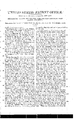
- the frame A is represented by red lines, which are not allowed to interfere with a view of those parts within it which would be in view were it removed, they are not therefore drawn in dotted lines.
- the coil of wire from which the blanksY are to be cut is placed on a reel, and is straightened as it enters the machine by passing 'alternately over and under the straightening rollers a, a, a.
- the wire is drawn into the machine', cut off, and headed by the action cams, and eccentric grooves upon levers which guide and control the apparatus used for these purposes, in a way to be now described.
- a main shaft B re-
- volving in suitable boxes is turned by means of a band pushing round the whirl, or pulley C, or by any suitable gearing, and on the opposite end of this shaft there is a iy wheel D, which is not shown in the elevation drawing No. l, as it would obscure parts which it is important to show.
- the wire is drawn into the machine by means of rods Y b, b, b, (shown separately in Fig. 7,) which are acted upon by the cams C C on the outside of the frame, the cam as shown in Drawing No. l, pressing as it revolves against the vertical arm A, which is adjustable on the rod, by means of a tightening screw.
- a similar cam, and rod are placed on the opposite side of the machine, the rod is strengthened by oblique braces to give it the4v requisite stiffness, but these braces are not shown in drawing.
- a reacting spring e is used to draw the rod back when not held by the cai/n.
- y f, f are nippers which seize the wire, and draw it 4forward to the extent desired by the action of the rod b, I), the nwire passes through a hole in the block E, where it is cut off by the cutting dies to be presently described.
- the nippers f, f, rest, 'and have their fulcra upon'a sliding plate g, g, the ends of which move freely in grooves under the plates 7L, 7L.
- the wedges z', z' hold the wire in its place ready to be drawn forward by the nip'pers y, f, they are closed upon the wire by the retracting of the nipper plate which is thereby brought into contact with them, and when the wire drawn forward by the nippers loosened.
- the wedges, and straightening rollers are affixed to the same sliding frame j, j, which is adjusted by the set screws 7c, 7c, that the wedges may be correctly acted upon rby the upper plate to cause this plate to slide back when not held forward a spring similar to those at e, e, rises from the middle of the frame, and acts upon thevunder part of it, this spring is seen at c, in the elevation.
- the head block E contains the cutting tongs which open, and close, and slide up, and down within it.
- the head of these tongs is seen at F, Fig. l, the opening or mortise, within which they slide being designated by the continuous line surround ⁇ ing that letter, and also F, Fig. 2, in this ligure that side of the head block, E, which is toward the heading die shown.
- the shanks of the cutting tongs extend down through the cross bar G, the mortises in this cross bar through which they pass allowing them to open, and close to the requisite distance, but the tongs rise, and fall with the rising, and falling of this bar, having checks, or notches which bear against its upper and lower sides as shown by the pins 7c, 7c.
- Z is the joint pin of the tongs which projects into, and slides in a slot m, through either Yside of the head block, thus serving to guide it up, and down.
- a, n are guidev rods to guide the bar G
- o, 0, are mortises, or openings which receive the ends of the levers by which it is raised, and lowered at the proper period.
- the tongs are represented as closed, and the cutting dies are not shown, they being situated on the opposite face of the tongs, and beingmade in the ordinary way. When the wire is fed in it passes between the dies, the tongs being then open, and the space p, being opposite to the hole through which the wire passes in front of the head block.
- the tongs When the wire has been drawn in the tongs are closed and it is cut off.
- the tongs are then raised, and the wire is carried up within the opening p, so as to bring its projecting end opposite to the heading die while the opposite end rests against the solid partrof the head block, which is there formed of steel to sustain, and resist the pressure of the heading die, when the heading is completed the tongs again descend, and a new piece of wire being fed in pushes the headed blank out, and occupies its place, for ordinary blanks.
- the opening p is conntersunk to form the under side of the head.
- the levers H, H, Fig. 4 serve to open, and close the tongs, g, g, being their fulcra, their ends 71, 7, being guided by the zigzag grooves in the wheels I, I, on the main shaft, B, as shown also in Fig. ⁇ l'.
- the notches at their ends S, S, embrace the Shanks of the tongs which slide up, and down freely within them.
- the levers J, J, 6, are for raising, and lowering the tongs their ends t, t, being alternately acted upon by the cams w, fw, seen in place in the shaft B, in Fig. l.
- the socket head I is a sliding belt passing through the socket head I), and carrying the heading die, which is to be either flat, or hollow according to the form to be given to the head of the blank.
- a machine of this kind will vary so materially in size, and in the proportion of its parts according to the size of the blank, to be cut, and headed, that I have deemed it superfluous, to give any scale, or estimation of these, nor will they be found necessary by any competent machinist who would not fail to construct it with the requisite strength, which is the main point in these particulars.
Landscapes
- Engineering & Computer Science (AREA)
- Mechanical Engineering (AREA)
- Wire Processing (AREA)
Description
UNTTEn sTaTns PATENT orricn.
JEREMIAH H. PIERSON, F RAMAPO, NEW YORK.
MAC'HNE FOR CUTTING AND HEADING WIRE Fon MANUFACTURING Woon SCREWS AND RIvETs.
Specification forming part of Letters Patent No. 86, dated November 26, v1836; Reissued'March 8, 1848. A Y i l machine on one side, and Figure l in Drawing No. 2, is a plan, or top view. The other figures on this sheet, show such parts in de- Vtail as is thought necessary7 so to represent.
In each of the figures corresponding parts are designated by the same letters of reference.
In the Drawing No. l, the frame A, is represented by red lines, which are not allowed to interfere with a view of those parts within it which would be in view were it removed, they are not therefore drawn in dotted lines. The coil of wire from which the blanksY are to be cut, is placed on a reel, and is straightened as it enters the machine by passing 'alternately over and under the straightening rollers a, a, a. The wire is drawn into the machine', cut off, and headed by the action cams, and eccentric grooves upon levers which guide and control the apparatus used for these purposes, in a way to be now described. A main shaft B, re-
volving in suitable boxes, is turned by means of a band pushing round the whirl, or pulley C, or by any suitable gearing, and on the opposite end of this shaft there is a iy wheel D, which is not shown in the elevation drawing No. l, as it would obscure parts which it is important to show. The wire is drawn into the machine by means of rods Y b, b, b, (shown separately in Fig. 7,) which are acted upon by the cams C C on the outside of the frame, the cam as shown in Drawing No. l, pressing as it revolves against the vertical arm A, which is adjustable on the rod, by means of a tightening screw. A similar cam, and rod are placed on the opposite side of the machine, the rod is strengthened by oblique braces to give it the4v requisite stiffness, but these braces are not shown in drawing. A reacting spring e, is used to draw the rod back when not held by the cai/n.
y f, f, are nippers which seize the wire, and draw it 4forward to the extent desired by the action of the rod b, I), the nwire passes through a hole in the block E, where it is cut off by the cutting dies to be presently described. The nippers f, f, rest, 'and have their fulcra upon'a sliding plate g, g, the ends of which move freely in grooves under the plates 7L, 7L. The wedges z', z', hold the wire in its place ready to be drawn forward by the nip'pers y, f, they are closed upon the wire by the retracting of the nipper plate which is thereby brought into contact with them, and when the wire drawn forward by the nippers loosened. The wedges, and straightening rollers are affixed to the same sliding frame j, j, which is adjusted by the set screws 7c, 7c, that the wedges may be correctly acted upon rby the upper plate to cause this plate to slide back when not held forward a spring similar to those at e, e, rises from the middle of the frame, and acts upon thevunder part of it, this spring is seen at c, in the elevation. The head block E, contains the cutting tongs which open, and close, and slide up, and down within it. The head of these tongs is seen at F, Fig. l, the opening or mortise, within which they slide being designated by the continuous line surround` ing that letter, and also F, Fig. 2, in this ligure that side of the head block, E, which is toward the heading die shown. The shanks of the cutting tongs extend down through the cross bar G, the mortises in this cross bar through which they pass allowing them to open, and close to the requisite distance, but the tongs rise, and fall with the rising, and falling of this bar, having checks, or notches which bear against its upper and lower sides as shown by the pins 7c, 7c.
Z, is the joint pin of the tongs which projects into, and slides in a slot m, through either Yside of the head block, thus serving to guide it up, and down. a, n, are guidev rods to guide the bar G, and o, 0, are mortises, or openings which receive the ends of the levers by which it is raised, and lowered at the proper period. The tongs are represented as closed, and the cutting dies are not shown, they being situated on the opposite face of the tongs, and beingmade in the ordinary way. When the wire is fed in it passes between the dies, the tongs being then open, and the space p, being opposite to the hole through which the wire passes in front of the head block. When the wire has been drawn in the tongs are closed and it is cut off. The tongs are then raised, and the wire is carried up within the opening p, so as to bring its projecting end opposite to the heading die while the opposite end rests against the solid partrof the head block, which is there formed of steel to sustain, and resist the pressure of the heading die, when the heading is completed the tongs again descend, and a new piece of wire being fed in pushes the headed blank out, and occupies its place, for ordinary blanks. The opening p, is conntersunk to form the under side of the head.
The levers H, H, Fig. 4, serve to open, and close the tongs, g, g, being their fulcra, their ends 71, 7, being guided by the zigzag grooves in the wheels I, I, on the main shaft, B, as shown also in Fig. `l'. The notches at their ends S, S, embrace the Shanks of the tongs which slide up, and down freely within them. The levers J, J, 6, are for raising, and lowering the tongs their ends t, t, being alternately acted upon by the cams w, fw, seen in place in the shaft B, in Fig. l. Their ends 0, 0, pass into the mortises o, 0, in the rail of the tongs their fulcra are at o, in a standard placed to receive them. Vhen the wire has been cut, and the tongs raised so as to present its projecting end to the heading die a cam 7a, Figs. 3, and 5, on the center of the shaft B, raises the progressive levers or toggle joint L, L, by its coming into contact with the lower end of the descending joint piece M. A guide piece N, is jointed to M, and to the frame to govern the motion of the togglejoint.
O, is a sliding belt passing through the socket head I), and carrying the heading die, which is to be either flat, or hollow according to the form to be given to the head of the blank. There are iron braces extending from the front head block E, to the back end of the frame to bind them together', and sustain them against the force of the toggle joint in the heading process, these are shown in the top view Fig. l, and are marked, w, fw, but they are omitted in the elevation, in order to alford a clearer view of the working parts.
A machine of this kind will vary so materially in size, and in the proportion of its parts according to the size of the blank, to be cut, and headed, that I have deemed it superfluous, to give any scale, or estimation of these, nor will they be found necessary by any competent machinist who would not fail to construct it with the requisite strength, which is the main point in these particulars.
Having thus fully described the construction of my said machine, and the manner in which the same operates, I do hereby declare that I do not intend to claim as my invention any of the individual parts of which the same is composed separately, and distinctly from the purposes for which I have employed them, and the manner in which I have combined them together. Cams, zigzag wheels, levers, toggle-joints, and the other individual parts described are the elements of numerous other machines. But
What I do claim as my invention is* The mode of feeding in the wire, combining the action of the nippers, and their sliding plate, with the wedges for holding the wire, and their adjustments, also in conjunction therewith the manner of cutting off the wire7 and raising, and depresesing the cutting tongs, with a concurrent action of the heading die, produced, and operating substantially in the manner herein set forth.
J ERM. I-I. PIERSON.
Witnesses:
ANTHONY HAUsToN, JAMES II. Ross.
[FIRST PRINTED 1914.]
Publications (1)
| Publication Number | Publication Date |
|---|---|
| US86A true US86A (en) | 1836-11-26 |
Family
ID=2060365
Family Applications (1)
| Application Number | Title | Priority Date | Filing Date |
|---|---|---|---|
| US86D Expired - Lifetime US86A (en) | Machine for cutting and heading wire for manufacturing wood |
Country Status (1)
| Country | Link |
|---|---|
| US (1) | US86A (en) |
Cited By (6)
| Publication number | Priority date | Publication date | Assignee | Title |
|---|---|---|---|---|
| WO2017004243A1 (en) | 2015-06-29 | 2017-01-05 | Caris Science, Inc. | Therapeutic oligonucleotides |
| WO2017019918A1 (en) | 2015-07-28 | 2017-02-02 | Caris Science, Inc. | Targeted oligonucleotides |
| WO2017205686A1 (en) | 2016-05-25 | 2017-11-30 | Caris Science, Inc. | Oligonucleotide probes and uses thereof |
| WO2019186514A2 (en) | 2018-03-30 | 2019-10-03 | Rheinische Friedrich-Wilhelms-Universitat Bonn | Aptamers for targeted activaton of t cell-mediated immunity |
| EP3828272A1 (en) | 2016-03-18 | 2021-06-02 | Caris Science, Inc. | Oligonucleotide probes and uses thereof |
| WO2022152770A1 (en) | 2021-01-14 | 2022-07-21 | Enyo Pharma | Synergistic effect of a fxr agonist and ifn for the treatment of hbv infection |
-
0
- US US86D patent/US86A/en not_active Expired - Lifetime
Cited By (7)
| Publication number | Priority date | Publication date | Assignee | Title |
|---|---|---|---|---|
| WO2017004243A1 (en) | 2015-06-29 | 2017-01-05 | Caris Science, Inc. | Therapeutic oligonucleotides |
| WO2017019918A1 (en) | 2015-07-28 | 2017-02-02 | Caris Science, Inc. | Targeted oligonucleotides |
| EP3828272A1 (en) | 2016-03-18 | 2021-06-02 | Caris Science, Inc. | Oligonucleotide probes and uses thereof |
| EP4339288A2 (en) | 2016-03-18 | 2024-03-20 | Caris Science, Inc. | Oligonucleotide probes and uses thereof |
| WO2017205686A1 (en) | 2016-05-25 | 2017-11-30 | Caris Science, Inc. | Oligonucleotide probes and uses thereof |
| WO2019186514A2 (en) | 2018-03-30 | 2019-10-03 | Rheinische Friedrich-Wilhelms-Universitat Bonn | Aptamers for targeted activaton of t cell-mediated immunity |
| WO2022152770A1 (en) | 2021-01-14 | 2022-07-21 | Enyo Pharma | Synergistic effect of a fxr agonist and ifn for the treatment of hbv infection |
Similar Documents
| Publication | Publication Date | Title |
|---|---|---|
| US86A (en) | Machine for cutting and heading wire for manufacturing wood | |
| US149A (en) | Machine eoe cutting and heading wire foe the manufacture oe wood | |
| US558673A (en) | Machine for making curved molding and embossing sheet metal | |
| US4346A (en) | Island | |
| US338079A (en) | Cornice-bending machine | |
| US6074A (en) | Machine fob making suspender-buckles | |
| US7200A (en) | Movement oe the pointing-dies in spike-machines | |
| US868792A (en) | Rod-bending machine. | |
| US221102A (en) | Improvement in machines for forming carriage-shackles | |
| US168689A (en) | Improvement in machines for shaping agricultural implements | |
| US821765A (en) | Machine for folding sheet metal. | |
| US345464A (en) | Staple-machine | |
| USRE108E (en) | pierson | |
| USRE43E (en) | Improvement in machines for making coopers and other rivets | |
| US66172A (en) | Improved machine foe making butt-hinges | |
| US307198A (en) | jordan | |
| US553908A (en) | Wire bending and cutting machine | |
| US445149A (en) | quant | |
| US1114888A (en) | Forming-machine. | |
| US160747A (en) | Improvement in pan-forming machines | |
| US120306A (en) | Improvement in wood-bending machines | |
| US507239A (en) | norton | |
| US508180A (en) | Half to john parkinson | |
| US389570A (en) | Die for forming spring-head clips | |
| US484836A (en) | williams |