US7712701B1 - Unmanned aerial vehicle with electrically powered, counterrotating ducted rotors - Google Patents
Unmanned aerial vehicle with electrically powered, counterrotating ducted rotors Download PDFInfo
- Publication number
- US7712701B1 US7712701B1 US11/351,775 US35177506A US7712701B1 US 7712701 B1 US7712701 B1 US 7712701B1 US 35177506 A US35177506 A US 35177506A US 7712701 B1 US7712701 B1 US 7712701B1
- Authority
- US
- United States
- Prior art keywords
- shroud
- bladed rotor
- unmanned aerial
- aerial vehicle
- axis
- Prior art date
- Legal status (The legal status is an assumption and is not a legal conclusion. Google has not performed a legal analysis and makes no representation as to the accuracy of the status listed.)
- Expired - Fee Related, expires
Links
- 235000019994 cava Nutrition 0.000 abstract description 5
- 230000009471 action Effects 0.000 abstract description 4
- 230000007246 mechanism Effects 0.000 description 7
- 239000002131 composite material Substances 0.000 description 4
- 229920000049 Carbon (fiber) Polymers 0.000 description 3
- 239000004917 carbon fiber Substances 0.000 description 3
- VNWKTOKETHGBQD-UHFFFAOYSA-N methane Chemical compound C VNWKTOKETHGBQD-UHFFFAOYSA-N 0.000 description 3
- 229920001453 Arcel Polymers 0.000 description 2
- 230000008859 change Effects 0.000 description 2
- 230000001066 destructive effect Effects 0.000 description 2
- 239000006260 foam Substances 0.000 description 2
- 230000008439 repair process Effects 0.000 description 2
- WHXSMMKQMYFTQS-UHFFFAOYSA-N Lithium Chemical compound [Li] WHXSMMKQMYFTQS-UHFFFAOYSA-N 0.000 description 1
- 239000004952 Polyamide Substances 0.000 description 1
- JDZCKJOXGCMJGS-UHFFFAOYSA-N [Li].[S] Chemical compound [Li].[S] JDZCKJOXGCMJGS-UHFFFAOYSA-N 0.000 description 1
- 238000002485 combustion reaction Methods 0.000 description 1
- 238000001816 cooling Methods 0.000 description 1
- 230000003247 decreasing effect Effects 0.000 description 1
- 239000000428 dust Substances 0.000 description 1
- 230000000694 effects Effects 0.000 description 1
- 239000002360 explosive Substances 0.000 description 1
- 239000000446 fuel Substances 0.000 description 1
- 238000009434 installation Methods 0.000 description 1
- 239000003562 lightweight material Substances 0.000 description 1
- 229910052744 lithium Inorganic materials 0.000 description 1
- 238000012423 maintenance Methods 0.000 description 1
- 239000000463 material Substances 0.000 description 1
- 238000005259 measurement Methods 0.000 description 1
- 230000003287 optical effect Effects 0.000 description 1
- 229920002647 polyamide Polymers 0.000 description 1
- 239000004576 sand Substances 0.000 description 1
Images


Classifications
-
- B—PERFORMING OPERATIONS; TRANSPORTING
- B64—AIRCRAFT; AVIATION; COSMONAUTICS
- B64C—AEROPLANES; HELICOPTERS
- B64C27/00—Rotorcraft; Rotors peculiar thereto
- B64C27/20—Rotorcraft characterised by having shrouded rotors, e.g. flying platforms
-
- B—PERFORMING OPERATIONS; TRANSPORTING
- B64—AIRCRAFT; AVIATION; COSMONAUTICS
- B64C—AEROPLANES; HELICOPTERS
- B64C39/00—Aircraft not otherwise provided for
- B64C39/02—Aircraft not otherwise provided for characterised by special use
- B64C39/024—Aircraft not otherwise provided for characterised by special use of the remote controlled vehicle type, i.e. RPV
-
- B—PERFORMING OPERATIONS; TRANSPORTING
- B64—AIRCRAFT; AVIATION; COSMONAUTICS
- B64U—UNMANNED AERIAL VEHICLES [UAV]; EQUIPMENT THEREFOR
- B64U30/00—Means for producing lift; Empennages; Arrangements thereof
- B64U30/20—Rotors; Rotor supports
- B64U30/26—Ducted or shrouded rotors
-
- B—PERFORMING OPERATIONS; TRANSPORTING
- B64—AIRCRAFT; AVIATION; COSMONAUTICS
- B64U—UNMANNED AERIAL VEHICLES [UAV]; EQUIPMENT THEREFOR
- B64U30/00—Means for producing lift; Empennages; Arrangements thereof
- B64U30/20—Rotors; Rotor supports
- B64U30/29—Constructional aspects of rotors or rotor supports; Arrangements thereof
-
- B—PERFORMING OPERATIONS; TRANSPORTING
- B64—AIRCRAFT; AVIATION; COSMONAUTICS
- B64U—UNMANNED AERIAL VEHICLES [UAV]; EQUIPMENT THEREFOR
- B64U10/00—Type of UAV
- B64U10/10—Rotorcrafts
- B64U10/13—Flying platforms
-
- B—PERFORMING OPERATIONS; TRANSPORTING
- B64—AIRCRAFT; AVIATION; COSMONAUTICS
- B64U—UNMANNED AERIAL VEHICLES [UAV]; EQUIPMENT THEREFOR
- B64U20/00—Constructional aspects of UAVs
- B64U20/90—Cooling
- B64U20/94—Cooling of rotors or rotor motors
-
- B—PERFORMING OPERATIONS; TRANSPORTING
- B64—AIRCRAFT; AVIATION; COSMONAUTICS
- B64U—UNMANNED AERIAL VEHICLES [UAV]; EQUIPMENT THEREFOR
- B64U2101/00—UAVs specially adapted for particular uses or applications
- B64U2101/30—UAVs specially adapted for particular uses or applications for imaging, photography or videography
- B64U2101/31—UAVs specially adapted for particular uses or applications for imaging, photography or videography for surveillance
-
- B—PERFORMING OPERATIONS; TRANSPORTING
- B64—AIRCRAFT; AVIATION; COSMONAUTICS
- B64U—UNMANNED AERIAL VEHICLES [UAV]; EQUIPMENT THEREFOR
- B64U2201/00—UAVs characterised by their flight controls
- B64U2201/20—Remote controls
-
- B—PERFORMING OPERATIONS; TRANSPORTING
- B64—AIRCRAFT; AVIATION; COSMONAUTICS
- B64U—UNMANNED AERIAL VEHICLES [UAV]; EQUIPMENT THEREFOR
- B64U30/00—Means for producing lift; Empennages; Arrangements thereof
- B64U30/20—Rotors; Rotor supports
-
- B—PERFORMING OPERATIONS; TRANSPORTING
- B64—AIRCRAFT; AVIATION; COSMONAUTICS
- B64U—UNMANNED AERIAL VEHICLES [UAV]; EQUIPMENT THEREFOR
- B64U30/00—Means for producing lift; Empennages; Arrangements thereof
- B64U30/20—Rotors; Rotor supports
- B64U30/29—Constructional aspects of rotors or rotor supports; Arrangements thereof
- B64U30/296—Rotors with variable spatial positions relative to the UAV body
-
- B—PERFORMING OPERATIONS; TRANSPORTING
- B64—AIRCRAFT; AVIATION; COSMONAUTICS
- B64U—UNMANNED AERIAL VEHICLES [UAV]; EQUIPMENT THEREFOR
- B64U50/00—Propulsion; Power supply
- B64U50/10—Propulsion
- B64U50/19—Propulsion using electrically powered motors
Definitions
- the disclosure relates to an unmanned aerial vehicle, in particular an aerial vehicle having counterrotating ducted rotors that are driven by electric motors and which has a low weight and a small profile.
- unmanned vehicles for performing control, surveillance, reconnaissance, communications, and other tasks.
- These include ground based remote-controlled wheeled or tracked vehicles, and aerial vehicles including the Honeywell Micro Air Vehicle, the Honeywell Kestrel, and the Allied Aerospace iSTAR.
- An unmanned aerial vehicle having counterrotating ducted rotors that are driven by electric motors.
- the vehicle has a low weight and a small profile.
- the unmanned aerial vehicle is suitable for a number of different tasks, including control, surveillance and reconnaissance, communication, and other tasks without exposing personnel to dangerous situations.
- the vehicle is particularly suited for entering buildings and other enclosed structures and spaces such as caves.
- the unmanned aerial vehicle can also be equipped for potential offensive actions.
- the vehicle is controlled remotely by an operator using a suitable controller, such as a lap top computer or a personal data device.
- a suitable controller such as a lap top computer or a personal data device.
- the vehicle can send information back to the controller relating to the task being performed.
- the vehicle is configured as a modular system, which enhances portability by humans and allows repair and refit of the vehicle tailored for a particular application.
- the size and weight of the vehicle are such as to further increase portability.
- the vehicle is configured to perform in environments where magnetometers, GPS and digital compasses are degraded.
- the unmanned aerial vehicle includes a shroud that is concentric about an axis, with the shroud having an interior space.
- a hub is disposed on the axis, with a first bladed rotor being rotatably mounted on the hub within the shroud for rotation in a first direction about an axis of rotation concentric with the axis of the shroud, and a second bladed rotor being rotatably mounted on the hub within the shroud for rotation in a second direction about an axis of rotation concentric with the axis of the shroud, where the second rotation direction being opposite the first rotation direction.
- a first electric motor is disposed in the hub and in driving engagement with the first bladed rotor for rotating the first bladed rotor in the first rotation direction
- a second electric motor is disposed in the hub and in driving engagement with the second bladed rotor for rotating the second bladed rotor in the second rotation direction.
- at least one battery is disposed in the interior space of the shroud providing electrical power to the first and second electric motors.
- the unmanned aerial vehicle includes a shroud that is concentric about an axis, with the shroud including a plurality of shroud sections each of which is separately detachable from the vehicle.
- a hub is disposed on the axis, with a first bladed rotor being rotatably mounted on the hub within the shroud for rotation in a first direction about an axis of rotation concentric with the axis of the shroud, and a second bladed rotor being rotatably mounted on the hub within the shroud for rotation in a second direction about an axis of rotation concentric with the axis of the shroud, where the second rotation direction being opposite the first rotation direction.
- a first electric motor is disposed in the hub and in driving engagement with the first bladed rotor for rotating the first bladed rotor in the first rotation direction
- a second electric motor is disposed in the hub and in driving engagement with the second bladed rotor for rotating the second bladed rotor in the second rotation direction.
- the vehicle includes at least one battery providing electrical power to the first and second electric motors.
- FIG. 1 is a perspective view of the unmanned aerial vehicle.
- FIG. 2 is a depiction of an exemplary use of the unmanned aerial vehicle.
- FIG. 3 is a top plan view of the unmanned aerial vehicle.
- FIG. 4 is a side view of the unmanned aerial vehicle.
- FIG. 5A is a close-up view of the hub of the unmanned aerial vehicle illustrating details of the passive control system for the upper bladed rotor.
- FIG. 5B is a close-up view of the hub illustrating details of the active control system of the lower bladed rotor.
- FIG. 5C illustrates control of the blade angle of the lower bladed rotor.
- FIG. 6 is a cross-sectional view through the hub to illustrate details of the drive mechanisms for rotating the bladed rotors.
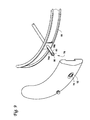
- FIG. 7 illustrates the shroud sections forming the shroud of the unmanned aerial vehicle.
- FIG. 8 is a close-up view of a portion of a shroud section connected to a ring.
- FIG. 9 details the non-destructive, detachable connection between the shroud sections and the ring.
- An unmanned aerial vehicle 10 having counterrotating ducted rotors that are driven by electric motors, with the vehicle having a low weight and a small profile.
- the unmanned aerial vehicle 10 is suitable for a number of different tasks, including control, surveillance and reconnaissance, communication, and other tasks without exposing personnel to dangerous situations.
- the vehicle 10 is particularly suited for entering buildings and other enclosed structures and spaces such as caves.
- the unmanned aerial vehicle can also be equipped for potential offensive actions.
- the vehicle 10 will be further described as being used in a military setting to enter a building 5 and perform reconnaissance therein, as shown in FIG. 2 .
- the vehicle 10 can be used in settings other than military, for example law enforcement.
- the vehicle can be used enter other man-made and naturally occurring structures, for example caves, and can be used in a manner that does not require entry into a building or other structure, for example open air surveillance and reconnaissance.
- the vehicle 10 can be used to perform tasks other than reconnaissance, including passive tasks such as control and communications, and aggressive tasks such as offensive action against a building occupant(s).
- the unmanned aerial vehicle 10 includes a non-rotating shroud 12 that is concentric about an axis A (see FIGS. 3 and 4 ), a non-rotating hub 14 that is disposed on the axis A, first and second bladed rotors 16 , 18 , and a non-rotating frame 20 that connects the shroud 12 to the hub 14 .
- the vehicle 10 is generally circular in configuration, having a relatively small profile with a maximum height H and maximum diameter D chosen to facilitate maneuverability within the building 5 .
- the vehicle 10 can have a maximum height of about 5.0 inches and a maximum diameter of about 22.0 inches.
- the vehicle 10 has a low weight to increase portability of the vehicle 10 , particularly by humans.
- the vehicle 10 preferably has a weight of less than about 5 pounds, more preferably a weight of about 3 pounds or less.
- the first and second rotors 16 , 18 counterrotate within and relative to the shroud 12 so that the rotation direction of the first rotor 16 is opposite to the rotation direction of the second rotor 18 .
- the first rotor 16 is mounted at the top of the hub 14 and the second rotor 18 is mounted at the bottom of the hub 14 so that the first rotor 16 is the upper or top rotor while the second rotor 18 is the lower or bottom rotor.
- the distance between the rotors 16 , 18 is about 25% of the radius of the first or second rotors 16 , 18 , with both rotors being surrounded by the shroud 12 .
- the first rotor 16 includes first and second blades 16 a , 16 b connected by a rod 22 .
- each end of the rod 22 is in the shape of a clevis, with the root ends of the blades 16 a , 16 b being received in the respective clevis and secured to the rod 22 by bolts 24 .
- the rod 22 is rotatably mounted on a pair of flanges 26 that are integral with a base plate 28 , to allow rotation of the rod 22 and thus change in the blade angle of the blades 16 a , 16 b .
- the base plate 28 is fixed to a drive shaft 30 that is in driving engagement with a drive mechanism for rotatably driving the first bladed rotor 16 .
- the drive shaft 30 is rotatably supported on the hub 14 by bearings.
- the second rotor 18 includes first and second blades 18 a , 18 b .
- the blade 18 a is connected to the blade 18 b by a rod 32 that extends through flanges 34 that are integral with a base plate 36 .
- the rod 32 is rotatably supported by the flanges 34 to allow rotation of the blades 18 a , 18 b to change the blade angle of the blades 18 a , 18 b .
- the base plate 36 is fixed to a drive shaft 38 that is in driving engagement with a drive mechanism for rotatably driving the first bladed rotor 16 .
- the drive shaft 38 is rotatably supported on the hub 14 by bearings.
- a passive control system 40 is connected to the first rotor 16 for controlling the plane of rotation of the first bladed rotor by changing the blade angles of the blades 16 a , 16 b .
- the passive control system 40 includes a weighted fly bar that includes a shaft 44 that is fixed to and extends through the rod 22 , and weights 46 , each having the same weight, at each end of the shaft 44 .
- an active control system 42 is connected to the second rotor 18 for controlling the plane of rotation of the second bladed rotor by changing the blade angles of the blades 18 a , 18 b .
- the active control system 42 includes a pair of servos 48 (only one servo is shown in FIG. 6 ) disposed within the hub 14 .
- a plate 49 having a pair of arms 49 a , 49 b is mounted under the housing of the hub 14 so as to be slideable in a direction perpendicular to the rotation axis of the rotor 18 as shown by the arrow in FIG. 5C .
- a slot 50 is formed in the end of the arm 49 b , while a hole 51 is formed in the arm 49 a .
- One servo 48 is linked to the arm 49 a by a link 100 having an offset pin 102 disposed in the hole 51 .
- the other servo 48 is linked to the arm 49 b by a link 104 having an offset pin 106 disposed in the slot 50 .
- a clevis 108 is connected to the plate 49 and at a generally right angle thereto so as to move with the plate.
- a pin 110 extends upwardly from the rod 32 , with the end of the pin 110 disposed between the arms of the clevis 108 .
- rotation of either servo 48 causes rotation of the respective link 100 , 104 , thereby actuating the offset pin 102 , 106 .
- the plate 49 will be forced to move in a direction perpendicular to the rotation axis of the rotor 18 . This causes the clevis 108 to move in the same direction, which actuates the pin 110 causing the rod 32 to rotate thereby changing the angle of the blades 18 a , 18 b.
- the weighted fly bar is directly connected to the blades 16 a , 16 b for automatically and equally changing the blade angles of the blades 16 a , 16 b .
- the weighted fly bar tends to return the vehicle 10 to a steady state hovering condition.
- the hub 14 rotatably supports the rotors 16 , 18 , and has a generally hollow interior in which electric motors 52 , 54 for driving the rotors 16 , 18 are disposed.
- the hub 14 can be made of a material providing good tensile strength and low weight, for example, carbon fiber polyamide composite.
- the electric motors 52 , 54 are, for example, 65 W motors.
- the hub 14 includes an opening 56 at the top thereof to provide access for installation and maintenance, and to provide an airflow path to allow cooling of the motors 52 , 54 .
- a filter (not shown) can be installed over the opening 56 to filter out sand and dust from the air.
- each drive mechanism includes a drive gear 58 connected to the output shaft 60 of the motor 52 , 54 , and a driven gear 62 that is connected to the respective drive shaft 30 , 38 .
- other drive mechanisms could be used to connect the motors 52 , 54 to the rotors 16 , 18 , for example a belt drive mechanism.
- the shroud 12 is formed of a plurality of shroud sections 12 a , 12 b , 12 c , 12 d that are detachably connected to the vehicle 10 .
- four shroud sections are used.
- a larger or smaller number of shroud sections can be used.
- the shroud sections 12 a - d in the illustrated embodiment are not of the same circumferential size as a result of the different functions of each section.
- the shroud sections could be made to have the same circumferential size if desired. Regardless of whether the shroud sections are of the same circumferential size or not, the shroud sections should combine to form a 360 degree circle.
- Each shroud section 12 a - d forms a module that contains elements used in the operation of the vehicle 10 .
- section 12 a can house one or more batteries 64 , for example lithium-based batteries, such as lithium sulphur batteries, or other comparable power supply, for providing power to the motors 52 , 54 .
- Section 12 b can house control equipment, for example various processors and electronics, used to control vehicle 10 flight and operations, including control of other shroud modules.
- Section 12 c can house a suitable payload specific to the intended use or application of the vehicle 10 .
- the section 12 c can house passive equipment such as one or more cameras 65 , an infrared illuminator, a microphone, and sensors, or offensive equipment such as weapons.
- Section 12 d can house communications equipment for enabling communications with a suitable controller 7 , such as a lap top computer or a personal data device (see FIG. 2 ).
- the shroud 12 contains one or more optic flow sensors.
- the optic flow sensors are used along with an inertial measurement unit for navigation of the vehicle 10 and to help the vehicle 10 avoid collisions with objects within the building.
- the use of optical flow sensors allows the vehicle to operate without using guidance systems such as GPS. As a result, the vehicle can be used in environments that are not suitable for GPS and other sensors or where the performance of GPS and other guidance systems are degraded, such as in caves.
- Each shroud section 12 a - d is made from durable, lightweight materials.
- each shroud section 12 a - d can be made from ARCEL® foam, a carbon fiber composite or combinations thereof.
- each shroud section 12 a - d can have a weight of about 53 grams before the addition of additional components.
- the total weight of the shroud sections 12 a - d with additional internal components can be, for example, approximately 2 pounds.
- the shroud sections 12 a - d are designed to be non-destructively detachably connected to the frame 20 to allow disassembly of the vehicle to increase portability, and to allow individual sections 12 a - d to be removed and replaced with other sections or for repair. Since the shroud sections 12 a - d are replaceable, the vehicle 10 can be tailored to differing uses and applications by replacing the shroud sections with sections suitable for the intended use of the vehicle.
- the detachable connection between the shroud sections and the frame 20 is preferably achieved using a non-destructive mechanical and electrical connection that permits removal of the sections without destroying or damaging the shroud sections or the frame.
- the frame 20 is used to connect the shroud 12 to the hub 14 .
- the frame 20 is designed to be stiff, have a low weight, and minimize the effect on the airflow through the vehicle 10 .
- the frame 20 includes a ring 66 that is concentric to the axis A, and rods 68 that are integral with the ring 66 and connect to the hub 14 , as shown in FIGS. 1 , 3 and 7 .
- the ring 66 and rods 68 can be made of, for example, a composite material, such as a carbon fiber composite.
- the rods 68 are preferably hollow tubes to reduce weight and act as conduits for wires passing from the shroud sections 12 a - d to the hub 14 .
- the rods 68 are preferably integrally formed with the ring 66 and the hub 14 .
- the rods 68 could be detachably connected to both the ring 66 and the hub 14 to allow replacement of the rods in the event of damage to the rods.
- each shroud section 12 a - d includes a channel 70 defined on the inner face thereof that receives the ring 66 therein.
- the inner surface of the ring is flush with the inner face of the shroud section, and a gap 72 is formed between the base of the “C” of the ring and the shroud section (see FIG. 8 ).
- the gap 72 provides space for routing wiring and the like.
- the ends 74 of the rods 68 extend past the ring 66 .
- a plurality of tabs 76 extend from the ring 66 .
- the projecting end 74 and the tabs 76 engage with suitable apertures 78 formed in the shroud sections.
- FIG. 9 Details of the connection between the shroud sections and the ring 66 are shown in FIG. 9 .
- the end of the tab 76 is bifurcated into two arms 76 a , 76 b that can flex toward each other.
- the tip of each arm 76 a , 76 b is provided with an enlarged shoulder 80 .
- the tab 76 is pushed into the aperture 78 , the arms 76 a , 76 b flex toward each other slightly, until the shoulders 80 project from the aperture 78 at which point the shoulders 80 snap in place to lock on to the surface 82 surrounding the aperture 78 .
- the projecting ends 74 are configured and function in the identical manner.
- This “snap-fit” connection between the ring 66 and the shroud section permits disconnection of the shroud section by squeezing the arms 76 a , 76 b toward each other to disengage the shoulders 80 from the surface 82 and thereby permitting removal of the shroud section.
- the vehicle 10 is operated remotely by an operator 8 , for example a soldier, using the controller 7 .
- the vehicle 10 is flown by the operator 8 through a suitable access point, such as through an open door or an open window.
- the cameras 65 on the vehicle 10 send back a video of the interior of the building 5 to the operator 8 .
- the operator 8 can fly the vehicle 10 throughout accessible portions of the interior of the building to allow the entire building to be scouted. As a result, the operator 8 can determine whether the building is occupied, how many occupants there are, and where in the building the occupants are located.
- the operator 8 can search for weapons, explosive devices, and other potential dangers prior to entering the building 5 .
Abstract
Description
Claims (19)
Priority Applications (1)
| Application Number | Priority Date | Filing Date | Title |
|---|---|---|---|
| US11/351,775 US7712701B1 (en) | 2006-02-10 | 2006-02-10 | Unmanned aerial vehicle with electrically powered, counterrotating ducted rotors |
Applications Claiming Priority (1)
| Application Number | Priority Date | Filing Date | Title |
|---|---|---|---|
| US11/351,775 US7712701B1 (en) | 2006-02-10 | 2006-02-10 | Unmanned aerial vehicle with electrically powered, counterrotating ducted rotors |
Publications (1)
| Publication Number | Publication Date |
|---|---|
| US7712701B1 true US7712701B1 (en) | 2010-05-11 |
Family
ID=42139235
Family Applications (1)
| Application Number | Title | Priority Date | Filing Date |
|---|---|---|---|
| US11/351,775 Expired - Fee Related US7712701B1 (en) | 2006-02-10 | 2006-02-10 | Unmanned aerial vehicle with electrically powered, counterrotating ducted rotors |
Country Status (1)
| Country | Link |
|---|---|
| US (1) | US7712701B1 (en) |
Cited By (47)
| Publication number | Priority date | Publication date | Assignee | Title |
|---|---|---|---|---|
| US20090125223A1 (en) * | 2006-03-31 | 2009-05-14 | Higgins Robert P | Video navigation |
| US20100003886A1 (en) * | 2008-07-02 | 2010-01-07 | Bob Cheng | Model helicopter |
| US20100102174A1 (en) * | 2006-07-31 | 2010-04-29 | University Of Florida Research Foundation, Inc. | Wingless Hovering Of Micro Air Vehicle |
| EP2217492A2 (en) * | 2007-11-02 | 2010-08-18 | GUILHOT-GAUDEFFROY, Michel | Rotor swashplate |
| US20110184593A1 (en) * | 2006-04-19 | 2011-07-28 | Swope John M | System for facilitating control of an aircraft |
| US20120056041A1 (en) * | 2010-09-02 | 2012-03-08 | Dream Space World Corporation | Unmanned Flying Vehicle Made With PCB |
| US20130206919A1 (en) * | 2010-11-12 | 2013-08-15 | Gabriel Shachor | Systems and methods for controlling an aerial unit |
| US20140008485A1 (en) * | 2012-07-06 | 2014-01-09 | Gert Magnus Lundgren | Foldable rise and stare vehicle |
| US20140151494A1 (en) * | 2012-11-30 | 2014-06-05 | Eurocopter Deutschland Gmbh | Vertical take-off and landing (vtol) aerial vehicle and method of operating such a vtol aerial vehicle |
| DE102014012801A1 (en) * | 2014-08-28 | 2016-03-03 | Frank Ketteler | Protective device for a propeller |
| US20160122012A1 (en) * | 2014-11-04 | 2016-05-05 | Lg Electronics Inc. | Drone |
| USD756842S1 (en) | 2014-08-21 | 2016-05-24 | Javad Gnss, Inc. | Unmanned aerial drone |
| BE1022965B1 (en) * | 2015-04-21 | 2016-10-24 | Airobot | Assembly for unmanned aircraft, unmanned aircraft with the assembly, and method for controlling it |
| US20170015417A1 (en) * | 2014-08-29 | 2017-01-19 | Reference Technologies Inc | Multi-Propulsion Design for Unmanned Aerial Systems |
| US9598171B2 (en) * | 2012-08-29 | 2017-03-21 | Zenon Dragon | Vehicle with aerial and ground mobility |
| WO2017049135A1 (en) * | 2015-09-20 | 2017-03-23 | Kerry Manning | Ducted fan propulsion system |
| US20170210480A1 (en) * | 2016-01-27 | 2017-07-27 | Sikorsky Aircraft Corporation | Rotor systems for rotorcraft |
| USD813315S1 (en) * | 2016-11-18 | 2018-03-20 | Eric Sweeney | Flying disk |
| USD815580S1 (en) * | 2016-04-19 | 2018-04-17 | Samsung Electronics Co., Ltd. | Drone |
| USD817252S1 (en) * | 2016-04-19 | 2018-05-08 | Samsung Electronics Co., Ltd. | Drone |
| USD817251S1 (en) * | 2016-04-19 | 2018-05-08 | Samsung Electronics Co., Ltd. | Drone |
| US9975633B1 (en) | 2016-05-10 | 2018-05-22 | Northrop Grumman Systems Corporation | Collapsible ducted fan unmanned aerial system |
| US10059437B2 (en) | 2015-01-08 | 2018-08-28 | Robert Stanley Cooper | Multi-rotor safety shield |
| US10093417B2 (en) | 2014-11-10 | 2018-10-09 | Ascent Aerosystems Inc. | Unmanned flying device |
| US10126745B2 (en) | 2015-01-04 | 2018-11-13 | Hangzhou Zero Zero Technology Co., Ltd. | System and method for automated aerial system operation |
| US10220954B2 (en) * | 2015-01-04 | 2019-03-05 | Zero Zero Robotics Inc | Aerial system thermal control system and method |
| US10222800B2 (en) | 2015-01-04 | 2019-03-05 | Hangzhou Zero Zero Technology Co., Ltd | System and method for automated aerial system operation |
| US10303185B2 (en) | 2017-01-23 | 2019-05-28 | Hangzhou Zero Zero Technology Co., Ltd. | Multi-camera system and method of use |
| US10358214B2 (en) | 2015-01-04 | 2019-07-23 | Hangzhou Zero Zro Technology Co., Ltd. | Aerial vehicle and method of operation |
| EP3517428A1 (en) * | 2018-01-26 | 2019-07-31 | AIRBUS HELICOPTERS DEUTSCHLAND GmbH | A shrouding for interacting with at least one rotor assembly |
| US10435144B2 (en) | 2016-04-24 | 2019-10-08 | Hangzhou Zero Zero Technology Co., Ltd. | Aerial system propulsion assembly and method of use |
| US10507914B2 (en) | 2013-03-15 | 2019-12-17 | Flir Detection, Inc. | Spooler for unmanned aerial vehicle system |
| US10696372B2 (en) * | 2017-09-29 | 2020-06-30 | Intel Corporation | Transformable unmanned vehicles and related methods |
| US10719080B2 (en) | 2015-01-04 | 2020-07-21 | Hangzhou Zero Zero Technology Co., Ltd. | Aerial system and detachable housing |
| US10745102B2 (en) * | 2017-07-17 | 2020-08-18 | Griff Aviation As | Swingable arm mount for an aerial vehicle having a lift generating means, and an aerial vehicle, advantageously a multicopter with a swingable arm mount |
| FR3092822A1 (en) | 2019-02-18 | 2020-08-21 | Safran | Electric thruster for aircraft and method of using such a thruster |
| US10814966B2 (en) | 2015-05-25 | 2020-10-27 | Dotterel Technologies Limited | Shroud for an aircraft |
| US20210253240A1 (en) * | 2020-02-14 | 2021-08-19 | The Aerospace Corporation | Long range endurance aero platform system |
| US11097828B2 (en) | 2017-07-24 | 2021-08-24 | Dotterel Technologies Limited | Shroud |
| US20210339855A1 (en) * | 2019-10-09 | 2021-11-04 | Kitty Hawk Corporation | Hybrid power systems for different modes of flight |
| DE102020121032A1 (en) | 2020-08-10 | 2022-02-10 | Dr. Ing. H.C. F. Porsche Aktiengesellschaft | Aircraft and its manufacture |
| DE102020121031A1 (en) | 2020-08-10 | 2022-02-10 | Dr. Ing. H.C. F. Porsche Aktiengesellschaft | Aircraft and its manufacture |
| US11407493B2 (en) * | 2020-09-01 | 2022-08-09 | California Institute Of Technology | Rotating shroud for rotator blade systems |
| US20230093447A1 (en) * | 2017-06-27 | 2023-03-23 | Bonavide (PTY) LTD | Rotary-wing unmanned aerial vehicle |
| US11721352B2 (en) | 2018-05-16 | 2023-08-08 | Dotterel Technologies Limited | Systems and methods for audio capture |
| GB2617597A (en) * | 2022-04-13 | 2023-10-18 | Greenjets Ltd | Electric propulsion systems |
| WO2023199801A1 (en) * | 2022-04-12 | 2023-10-19 | 株式会社石川エナジーリサーチ | Flying device |
Citations (21)
| Publication number | Priority date | Publication date | Assignee | Title |
|---|---|---|---|---|
| US1541976A (en) * | 1922-04-10 | 1925-06-16 | Albin K Longren | Fuselage |
| US3135481A (en) * | 1961-07-17 | 1964-06-02 | Helipod Inc | Ducted rotor aircraft |
| US3722830A (en) * | 1971-02-12 | 1973-03-27 | G Barber | Helicopter type vehicle |
| US4955560A (en) * | 1989-03-30 | 1990-09-11 | Nishina Edward T | Electro motor helicopter |
| US5150857A (en) | 1991-08-13 | 1992-09-29 | United Technologies Corporation | Shroud geometry for unmanned aerial vehicles |
| US5152478A (en) * | 1990-05-18 | 1992-10-06 | United Technologies Corporation | Unmanned flight vehicle including counter rotating rotors positioned within a toroidal shroud and operable to provide all required vehicle flight controls |
| US5277380A (en) | 1992-06-22 | 1994-01-11 | United Technologies Corporation | Toroidal fuselage structure for unmanned aerial vehicles having ducted, coaxial, counter-rotating rotors |
| US5419513A (en) * | 1993-05-11 | 1995-05-30 | United Technologies Corporation | Ancillary aerodynamic structures for an unmanned aerial vehicle having ducted, coaxial counter-rotating rotors |
| US5575438A (en) | 1994-05-09 | 1996-11-19 | United Technologies Corporation | Unmanned VTOL ground surveillance vehicle |
| US6070831A (en) * | 1997-02-05 | 2000-06-06 | Vassiliev; Anatoli J. | Aircraft for passenger and/or cargo transport |
| US6270038B1 (en) | 1999-04-22 | 2001-08-07 | Sikorsky Aircraft Corporation | Unmanned aerial vehicle with counter-rotating ducted rotors and shrouded pusher-prop |
| US6450445B1 (en) | 1998-12-11 | 2002-09-17 | Moller International, Inc. | Stabilizing control apparatus for robtic or remotely controlled flying platform |
| US6592071B2 (en) | 2001-09-25 | 2003-07-15 | Sikorsky Aircraft Corporation | Flight control system for a hybrid aircraft in the lift axis |
| US6672538B2 (en) | 2002-05-23 | 2004-01-06 | Sikorsky Aircraft Corporation | Transmission for a coaxial counter rotating rotor system |
| US6694228B2 (en) | 2002-05-09 | 2004-02-17 | Sikorsky Aircraft Corporation | Control system for remotely operated vehicles for operational payload employment |
| US6691949B2 (en) | 2001-07-06 | 2004-02-17 | The Charles Stark Draper Laboratory, Inc. | Vertical takeoff and landing aerial vehicle |
| US6758436B2 (en) * | 2001-11-07 | 2004-07-06 | Rehco, Llc | Pneumatic driven propeller related vehicles |
| US20040129833A1 (en) | 2002-07-26 | 2004-07-08 | C.R.F. Societa Consortile Per Azioni | VTOL micro-aircraft |
| US6840480B2 (en) * | 2001-09-27 | 2005-01-11 | Ernest A. Carroll | Miniature, unmanned aircraft with interchangeable data module |
| US20050061910A1 (en) * | 2002-03-06 | 2005-03-24 | Aloys Wobben | Aircraft |
| US20050082421A1 (en) | 2003-07-30 | 2005-04-21 | C.R.F. Societa Consortile Per Azioni | Flying machine |
-
2006
- 2006-02-10 US US11/351,775 patent/US7712701B1/en not_active Expired - Fee Related
Patent Citations (21)
| Publication number | Priority date | Publication date | Assignee | Title |
|---|---|---|---|---|
| US1541976A (en) * | 1922-04-10 | 1925-06-16 | Albin K Longren | Fuselage |
| US3135481A (en) * | 1961-07-17 | 1964-06-02 | Helipod Inc | Ducted rotor aircraft |
| US3722830A (en) * | 1971-02-12 | 1973-03-27 | G Barber | Helicopter type vehicle |
| US4955560A (en) * | 1989-03-30 | 1990-09-11 | Nishina Edward T | Electro motor helicopter |
| US5152478A (en) * | 1990-05-18 | 1992-10-06 | United Technologies Corporation | Unmanned flight vehicle including counter rotating rotors positioned within a toroidal shroud and operable to provide all required vehicle flight controls |
| US5150857A (en) | 1991-08-13 | 1992-09-29 | United Technologies Corporation | Shroud geometry for unmanned aerial vehicles |
| US5277380A (en) | 1992-06-22 | 1994-01-11 | United Technologies Corporation | Toroidal fuselage structure for unmanned aerial vehicles having ducted, coaxial, counter-rotating rotors |
| US5419513A (en) * | 1993-05-11 | 1995-05-30 | United Technologies Corporation | Ancillary aerodynamic structures for an unmanned aerial vehicle having ducted, coaxial counter-rotating rotors |
| US5575438A (en) | 1994-05-09 | 1996-11-19 | United Technologies Corporation | Unmanned VTOL ground surveillance vehicle |
| US6070831A (en) * | 1997-02-05 | 2000-06-06 | Vassiliev; Anatoli J. | Aircraft for passenger and/or cargo transport |
| US6450445B1 (en) | 1998-12-11 | 2002-09-17 | Moller International, Inc. | Stabilizing control apparatus for robtic or remotely controlled flying platform |
| US6270038B1 (en) | 1999-04-22 | 2001-08-07 | Sikorsky Aircraft Corporation | Unmanned aerial vehicle with counter-rotating ducted rotors and shrouded pusher-prop |
| US6691949B2 (en) | 2001-07-06 | 2004-02-17 | The Charles Stark Draper Laboratory, Inc. | Vertical takeoff and landing aerial vehicle |
| US6592071B2 (en) | 2001-09-25 | 2003-07-15 | Sikorsky Aircraft Corporation | Flight control system for a hybrid aircraft in the lift axis |
| US6840480B2 (en) * | 2001-09-27 | 2005-01-11 | Ernest A. Carroll | Miniature, unmanned aircraft with interchangeable data module |
| US6758436B2 (en) * | 2001-11-07 | 2004-07-06 | Rehco, Llc | Pneumatic driven propeller related vehicles |
| US20050061910A1 (en) * | 2002-03-06 | 2005-03-24 | Aloys Wobben | Aircraft |
| US6694228B2 (en) | 2002-05-09 | 2004-02-17 | Sikorsky Aircraft Corporation | Control system for remotely operated vehicles for operational payload employment |
| US6672538B2 (en) | 2002-05-23 | 2004-01-06 | Sikorsky Aircraft Corporation | Transmission for a coaxial counter rotating rotor system |
| US20040129833A1 (en) | 2002-07-26 | 2004-07-08 | C.R.F. Societa Consortile Per Azioni | VTOL micro-aircraft |
| US20050082421A1 (en) | 2003-07-30 | 2005-04-21 | C.R.F. Societa Consortile Per Azioni | Flying machine |
Non-Patent Citations (2)
| Title |
|---|
| "Handheld Spy Chopper." Popular Science, Sep. 2008, pp. 62-63. |
| Information on Competitors UAV's. |
Cited By (69)
| Publication number | Priority date | Publication date | Assignee | Title |
|---|---|---|---|---|
| US20090125223A1 (en) * | 2006-03-31 | 2009-05-14 | Higgins Robert P | Video navigation |
| US8666661B2 (en) * | 2006-03-31 | 2014-03-04 | The Boeing Company | Video navigation |
| US20110184593A1 (en) * | 2006-04-19 | 2011-07-28 | Swope John M | System for facilitating control of an aircraft |
| US8960595B2 (en) * | 2006-07-31 | 2015-02-24 | University Of Florida Research Foundation, Inc. | Wingless hovering of micro air vehicle |
| US20100102174A1 (en) * | 2006-07-31 | 2010-04-29 | University Of Florida Research Foundation, Inc. | Wingless Hovering Of Micro Air Vehicle |
| US8382029B2 (en) * | 2006-07-31 | 2013-02-26 | University Of Florida Research Foundation, Inc. | Wingless hovering of micro air vehicle |
| EP2217492A2 (en) * | 2007-11-02 | 2010-08-18 | GUILHOT-GAUDEFFROY, Michel | Rotor swashplate |
| US20100003886A1 (en) * | 2008-07-02 | 2010-01-07 | Bob Cheng | Model helicopter |
| US8702466B2 (en) * | 2008-07-02 | 2014-04-22 | Asian Express Holdings Limited | Model helicopter |
| US20120056041A1 (en) * | 2010-09-02 | 2012-03-08 | Dream Space World Corporation | Unmanned Flying Vehicle Made With PCB |
| US20130206919A1 (en) * | 2010-11-12 | 2013-08-15 | Gabriel Shachor | Systems and methods for controlling an aerial unit |
| US8844860B2 (en) * | 2012-07-06 | 2014-09-30 | Lapcad Engineering, Inc. | Foldable rise and stare vehicle |
| US20140008485A1 (en) * | 2012-07-06 | 2014-01-09 | Gert Magnus Lundgren | Foldable rise and stare vehicle |
| US9598171B2 (en) * | 2012-08-29 | 2017-03-21 | Zenon Dragon | Vehicle with aerial and ground mobility |
| US20140151494A1 (en) * | 2012-11-30 | 2014-06-05 | Eurocopter Deutschland Gmbh | Vertical take-off and landing (vtol) aerial vehicle and method of operating such a vtol aerial vehicle |
| US11180249B2 (en) | 2013-03-15 | 2021-11-23 | Flir Detection, Inc. | Spooler for unmanned aerial vehicle system |
| US11661187B2 (en) | 2013-03-15 | 2023-05-30 | Teledyne Flir Detection, Inc. | Spooler for unmanned aerial vehicle system |
| US10507914B2 (en) | 2013-03-15 | 2019-12-17 | Flir Detection, Inc. | Spooler for unmanned aerial vehicle system |
| USD756842S1 (en) | 2014-08-21 | 2016-05-24 | Javad Gnss, Inc. | Unmanned aerial drone |
| DE102014012801A1 (en) * | 2014-08-28 | 2016-03-03 | Frank Ketteler | Protective device for a propeller |
| DE102014012801A8 (en) * | 2014-08-28 | 2016-06-09 | Frank Ketteler | Protective device for a propeller |
| US20170015417A1 (en) * | 2014-08-29 | 2017-01-19 | Reference Technologies Inc | Multi-Propulsion Design for Unmanned Aerial Systems |
| US20160122012A1 (en) * | 2014-11-04 | 2016-05-05 | Lg Electronics Inc. | Drone |
| US9981744B2 (en) * | 2014-11-04 | 2018-05-29 | Lg Electronics Inc. | Drone |
| US11292595B2 (en) | 2014-11-10 | 2022-04-05 | Ascent Aerosystems Inc. | Unmanned flying device |
| US10093417B2 (en) | 2014-11-10 | 2018-10-09 | Ascent Aerosystems Inc. | Unmanned flying device |
| US10222800B2 (en) | 2015-01-04 | 2019-03-05 | Hangzhou Zero Zero Technology Co., Ltd | System and method for automated aerial system operation |
| US10528049B2 (en) | 2015-01-04 | 2020-01-07 | Hangzhou Zero Zero Technology Co., Ltd. | System and method for automated aerial system operation |
| US10824149B2 (en) | 2015-01-04 | 2020-11-03 | Hangzhou Zero Zero Technology Co., Ltd. | System and method for automated aerial system operation |
| US10126745B2 (en) | 2015-01-04 | 2018-11-13 | Hangzhou Zero Zero Technology Co., Ltd. | System and method for automated aerial system operation |
| US10824167B2 (en) | 2015-01-04 | 2020-11-03 | Hangzhou Zero Zero Technology Co., Ltd. | System and method for automated aerial system operation |
| US10220954B2 (en) * | 2015-01-04 | 2019-03-05 | Zero Zero Robotics Inc | Aerial system thermal control system and method |
| US10719080B2 (en) | 2015-01-04 | 2020-07-21 | Hangzhou Zero Zero Technology Co., Ltd. | Aerial system and detachable housing |
| US10358214B2 (en) | 2015-01-04 | 2019-07-23 | Hangzhou Zero Zro Technology Co., Ltd. | Aerial vehicle and method of operation |
| US10059437B2 (en) | 2015-01-08 | 2018-08-28 | Robert Stanley Cooper | Multi-rotor safety shield |
| BE1022965B1 (en) * | 2015-04-21 | 2016-10-24 | Airobot | Assembly for unmanned aircraft, unmanned aircraft with the assembly, and method for controlling it |
| US10814966B2 (en) | 2015-05-25 | 2020-10-27 | Dotterel Technologies Limited | Shroud for an aircraft |
| WO2017049135A1 (en) * | 2015-09-20 | 2017-03-23 | Kerry Manning | Ducted fan propulsion system |
| US20170210480A1 (en) * | 2016-01-27 | 2017-07-27 | Sikorsky Aircraft Corporation | Rotor systems for rotorcraft |
| US10150567B2 (en) * | 2016-01-27 | 2018-12-11 | Sikorsky Aircraft Corporation | Rotor systems for rotorcraft |
| USD815580S1 (en) * | 2016-04-19 | 2018-04-17 | Samsung Electronics Co., Ltd. | Drone |
| USD817252S1 (en) * | 2016-04-19 | 2018-05-08 | Samsung Electronics Co., Ltd. | Drone |
| USD817251S1 (en) * | 2016-04-19 | 2018-05-08 | Samsung Electronics Co., Ltd. | Drone |
| US10435144B2 (en) | 2016-04-24 | 2019-10-08 | Hangzhou Zero Zero Technology Co., Ltd. | Aerial system propulsion assembly and method of use |
| US11027833B2 (en) | 2016-04-24 | 2021-06-08 | Hangzhou Zero Zero Technology Co., Ltd. | Aerial system propulsion assembly and method of use |
| US9975633B1 (en) | 2016-05-10 | 2018-05-22 | Northrop Grumman Systems Corporation | Collapsible ducted fan unmanned aerial system |
| USD813315S1 (en) * | 2016-11-18 | 2018-03-20 | Eric Sweeney | Flying disk |
| US10303185B2 (en) | 2017-01-23 | 2019-05-28 | Hangzhou Zero Zero Technology Co., Ltd. | Multi-camera system and method of use |
| US20230093447A1 (en) * | 2017-06-27 | 2023-03-23 | Bonavide (PTY) LTD | Rotary-wing unmanned aerial vehicle |
| US10745102B2 (en) * | 2017-07-17 | 2020-08-18 | Griff Aviation As | Swingable arm mount for an aerial vehicle having a lift generating means, and an aerial vehicle, advantageously a multicopter with a swingable arm mount |
| US11097828B2 (en) | 2017-07-24 | 2021-08-24 | Dotterel Technologies Limited | Shroud |
| US10696372B2 (en) * | 2017-09-29 | 2020-06-30 | Intel Corporation | Transformable unmanned vehicles and related methods |
| EP3517428A1 (en) * | 2018-01-26 | 2019-07-31 | AIRBUS HELICOPTERS DEUTSCHLAND GmbH | A shrouding for interacting with at least one rotor assembly |
| US11721352B2 (en) | 2018-05-16 | 2023-08-08 | Dotterel Technologies Limited | Systems and methods for audio capture |
| WO2020169497A1 (en) | 2019-02-18 | 2020-08-27 | Safran | Electric propulsion unit for an aircraft and method for using such a propulsion unit |
| FR3092822A1 (en) | 2019-02-18 | 2020-08-21 | Safran | Electric thruster for aircraft and method of using such a thruster |
| US11787537B2 (en) * | 2019-10-09 | 2023-10-17 | Kitty Hawk Corporation | Hybrid power systems for different modes of flight |
| US20210339855A1 (en) * | 2019-10-09 | 2021-11-04 | Kitty Hawk Corporation | Hybrid power systems for different modes of flight |
| US11851178B2 (en) * | 2020-02-14 | 2023-12-26 | The Aerospace Corporation | Long range endurance aero platform system |
| US20210253240A1 (en) * | 2020-02-14 | 2021-08-19 | The Aerospace Corporation | Long range endurance aero platform system |
| CN114074758A (en) * | 2020-08-10 | 2022-02-22 | 保时捷股份公司 | Aircraft and production of aircraft |
| US20220041274A1 (en) * | 2020-08-10 | 2022-02-10 | Dr. Ing. H.C. F. Porsche Aktiengesellschaft | Aircraft, and the production thereof |
| DE102020121031A1 (en) | 2020-08-10 | 2022-02-10 | Dr. Ing. H.C. F. Porsche Aktiengesellschaft | Aircraft and its manufacture |
| CN114074758B (en) * | 2020-08-10 | 2023-11-21 | 保时捷股份公司 | Aircraft and production of an aircraft |
| DE102020121032A1 (en) | 2020-08-10 | 2022-02-10 | Dr. Ing. H.C. F. Porsche Aktiengesellschaft | Aircraft and its manufacture |
| US11407493B2 (en) * | 2020-09-01 | 2022-08-09 | California Institute Of Technology | Rotating shroud for rotator blade systems |
| WO2023199801A1 (en) * | 2022-04-12 | 2023-10-19 | 株式会社石川エナジーリサーチ | Flying device |
| GB2617597A (en) * | 2022-04-13 | 2023-10-18 | Greenjets Ltd | Electric propulsion systems |
| WO2023199071A1 (en) * | 2022-04-13 | 2023-10-19 | Greenjets Limited | Electric propulsion systems |
Similar Documents
| Publication | Publication Date | Title |
|---|---|---|
| US7712701B1 (en) | Unmanned aerial vehicle with electrically powered, counterrotating ducted rotors | |
| JP4499155B2 (en) | Rotor transportation means | |
| US20200331606A1 (en) | Aerial vehicle with uncoupled heading and orientation | |
| RU2627220C1 (en) | Vertical takeoff and landing aircraft | |
| KR102054119B1 (en) | Aircraft | |
| AU2013300151B2 (en) | Rotary wing vehicle | |
| US8794566B2 (en) | Vehicle capable of stabilizing a payload when in motion | |
| US8386095B2 (en) | Performing corrective action on unmanned aerial vehicle using one axis of three-axis magnetometer | |
| US8328130B2 (en) | Vertical take off and landing unmanned aerial vehicle airframe structure | |
| US20100108807A1 (en) | Tethered hovering platform | |
| US20060284002A1 (en) | Unmanned Urban Aerial Vehicle | |
| CN103025609A (en) | Reconfigurable battery-operated vehicle system | |
| WO2018148636A1 (en) | Weather sensing | |
| EP2193994A2 (en) | UAV ducted fan swept and lean stator design | |
| KR20160098807A (en) | A drone having high accessibility | |
| KR20130093867A (en) | Hybrid unmanned aerial vehicle | |
| JP2010254264A (en) | Unmanned aircraft landing and departing perpendicularly by tilt wing mechanism | |
| KR20180065963A (en) | Drone having self-generator | |
| US20090138140A1 (en) | Vehicular linear sensor system | |
| RU2603302C1 (en) | Vertical take-off and landing aircraft | |
| US8991742B2 (en) | Asymmetrical single main rotor unmanned aerial vehicle | |
| US20220219815A1 (en) | Unmanned Aerial Drone Crane | |
| KR102101636B1 (en) | Dron | |
| Duranti et al. | Linkmav, a protoype rotary wing micro aerial vehicle | |
| US11679892B2 (en) | Unmanned aerial vehicle parallel hybrid drive assembly with continuous belt tension modulation |
Legal Events
| Date | Code | Title | Description |
|---|---|---|---|
| AS | Assignment |
Owner name: LOCKHEED MARTIN CORPORATION,MARYLAND Free format text: ASSIGNMENT OF ASSIGNORS INTEREST;ASSIGNORS:EHRMANTRAUT, ADAM S.;MAUST, ANDREW M.;JOHNSON, PETER K.;SIGNING DATES FROM 20061113 TO 20061114;REEL/FRAME:018534/0749 |
|
| STCF | Information on status: patent grant |
Free format text: PATENTED CASE |
|
| FPAY | Fee payment |
Year of fee payment: 4 |
|
| MAFP | Maintenance fee payment |
Free format text: PAYMENT OF MAINTENANCE FEE, 8TH YEAR, LARGE ENTITY (ORIGINAL EVENT CODE: M1552) Year of fee payment: 8 |
|
| FEPP | Fee payment procedure |
Free format text: MAINTENANCE FEE REMINDER MAILED (ORIGINAL EVENT CODE: REM.); ENTITY STATUS OF PATENT OWNER: LARGE ENTITY |
|
| LAPS | Lapse for failure to pay maintenance fees |
Free format text: PATENT EXPIRED FOR FAILURE TO PAY MAINTENANCE FEES (ORIGINAL EVENT CODE: EXP.); ENTITY STATUS OF PATENT OWNER: LARGE ENTITY |
|
| STCH | Information on status: patent discontinuation |
Free format text: PATENT EXPIRED DUE TO NONPAYMENT OF MAINTENANCE FEES UNDER 37 CFR 1.362 |
|
| FP | Lapsed due to failure to pay maintenance fee |
Effective date: 20220511 |