US7694569B2 - Phased array ultrasonic water wedge apparatus - Google Patents
Phased array ultrasonic water wedge apparatus Download PDFInfo
- Publication number
- US7694569B2 US7694569B2 US10/925,343 US92534304A US7694569B2 US 7694569 B2 US7694569 B2 US 7694569B2 US 92534304 A US92534304 A US 92534304A US 7694569 B2 US7694569 B2 US 7694569B2
- Authority
- US
- United States
- Prior art keywords
- phased array
- housing
- probe assembly
- ultrasonic probe
- accordance
- Prior art date
- Legal status (The legal status is an assumption and is not a legal conclusion. Google has not performed a legal analysis and makes no representation as to the accuracy of the status listed.)
- Expired - Fee Related, expires
Links
Images


Classifications
-
- G—PHYSICS
- G01—MEASURING; TESTING
- G01N—INVESTIGATING OR ANALYSING MATERIALS BY DETERMINING THEIR CHEMICAL OR PHYSICAL PROPERTIES
- G01N29/00—Investigating or analysing materials by the use of ultrasonic, sonic or infrasonic waves; Visualisation of the interior of objects by transmitting ultrasonic or sonic waves through the object
- G01N29/22—Details, e.g. general constructional or apparatus details
- G01N29/26—Arrangements for orientation or scanning by relative movement of the head and the sensor
- G01N29/262—Arrangements for orientation or scanning by relative movement of the head and the sensor by electronic orientation or focusing, e.g. with phased arrays
-
- G—PHYSICS
- G01—MEASURING; TESTING
- G01N—INVESTIGATING OR ANALYSING MATERIALS BY DETERMINING THEIR CHEMICAL OR PHYSICAL PROPERTIES
- G01N29/00—Investigating or analysing materials by the use of ultrasonic, sonic or infrasonic waves; Visualisation of the interior of objects by transmitting ultrasonic or sonic waves through the object
- G01N29/04—Analysing solids
-
- G—PHYSICS
- G01—MEASURING; TESTING
- G01N—INVESTIGATING OR ANALYSING MATERIALS BY DETERMINING THEIR CHEMICAL OR PHYSICAL PROPERTIES
- G01N29/00—Investigating or analysing materials by the use of ultrasonic, sonic or infrasonic waves; Visualisation of the interior of objects by transmitting ultrasonic or sonic waves through the object
- G01N29/22—Details, e.g. general constructional or apparatus details
- G01N29/225—Supports, positioning or alignment in moving situation
-
- G—PHYSICS
- G01—MEASURING; TESTING
- G01N—INVESTIGATING OR ANALYSING MATERIALS BY DETERMINING THEIR CHEMICAL OR PHYSICAL PROPERTIES
- G01N2291/00—Indexing codes associated with group G01N29/00
- G01N2291/26—Scanned objects
- G01N2291/263—Surfaces
- G01N2291/2634—Surfaces cylindrical from outside
Definitions
- This invention relates generally to ultrasonic inspection of dissimilar metal welds, and more particularly ultrasonic inspection of dissimilar metal welds with phased array transducers.
- Pipe welds in, for example, nuclear reactors have been examined with ultrasonic transducers using 45° and 60° refracted longitudinal waves. These angles have been established as the “norm” based on the weld configurations, ultrasonic theory, and field experience.
- the pipes are raster scanned in four directions to completely examine the weld volume which is very time consuming. Problems are sometimes experienced with the setup of the manipulator that delivers the ultrasonic transducers to the weld, and more importantly with the contact between the transducers and the specimen being examined. If continuous contact between the transducer and the pipe is not maintained, the scan data collected will be flawed which can result in time consuming rescans or missed defect detections.
- Phased array ultrasonic probes have been developed that increase examination efficiency of conventional ultrasonic examination techniques by electronically steering the ultrasonic beam through a given range of angles.
- One major problem that still exists is the contact between the phased array ultrasonic transducer and the specimen being examined.
- Complex gimbling mechanisms that apply downward pressure on the transducers have been used to attempt to overcome this problem.
- other issues, for example, improper scanner setup and irregularities in the pipe surface can also effect inspection accuracy.
- a phased array ultrasonic probe assembly in one aspect, includes a housing and a phased array transducer supported inside the housing.
- the housing includes a first side wall and an opposing second side wall, and a first end wall and an opposing second end wall.
- the first and second side walls and the first and second end walls define a housing cavity in which the phased array transducer is positioned.
- the first and second side walls each have an inside surface that include a plurality of projections.
- a phased array ultrasonic probe assembly in another aspect, includes a housing and a phased array transducer pivotably mounted inside the housing.
- the phased array transducer includes a plurality of elements.
- the housing includes a first side wall and an opposing second side wall, and a first end wall and an opposing second end wall.
- the first and second side walls and the first and second end walls define a housing cavity in which the phased array transducer is positioned.
- the first and second side walls each have an inside surface that include a plurality of projections.
- a method of inspecting a portion of a weld in a metal object using a phased array ultrasonic probe assembly includes a housing and a phased array transducer pivotably mounted inside the housing.
- the housing includes a first side wall and an opposing second side wall, and a first end wall and an opposing second end wall.
- the first and second side walls and the first and second end walls define a housing cavity in which the phased array transducer is positioned.
- the first and second side walls each have an inside surface that includes a plurality of projections.
- the method includes positioning the phased array ultrasonic probe assembly adjacent an outer surface of the portion of the weld to be inspected, adding a fluid to the housing cavity, and scanning the weld.
- FIG. 1 is a perspective illustration of a phased array ultrasonic probe assembly in accordance with an embodiment of the present invention.
- FIG. 2 is a sectional illustration of a side wall of the phased array ultrasonic probe assembly shown in FIG. 1 .
- FIG. 3 is a sectional illustration of an end wall of the phased array ultrasonic probe assembly shown in FIG. 1 .
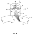
- FIG. 4 is a side illustration of the phased array ultrasonic probe assembly shown in FIG. 1 mounted on a pipe.
- FIG. 5 is a schematic illustration of the phased array ultrasonic transducer shown in FIG. 1 .
- a phased array ultrasonic probe assembly that includes a housing and a phased array transducer supported inside the housing is described below in detail.
- the housing includes opposing side walls having a plurality of “saw tooth” projections, and opposing end walls each having a at least one “saw tooth”, or triangle shaped, projection.
- the housing holds the phased array ultrasonic transducer in a standing column of water. The water fills the volume between the bottom of the transducer and the material that is being examined and permits for the ultrasonic sound waves to travel from the probe directly to the material with no break in contact. Sound exits the transducer at a predetermined angle and travels through the water until it comes in contact with the material where a velocity change is experienced.
- the change in speed causes the sound to refract as it penetrates that material permitting the weld volume to be inspected using the predetermined angle.
- the walls of the housing are designed to absorb or scatter the near surface reflectors which improves resolution. Both circumferential and axial flaws can be identified. The circumferential flaws are detected when the transducer is perpendicular to the longitudinal axis of the pipe. To detect axial flaws, the transducer is rotated along the longitudinal axis of the pipe.
- FIG. 1 is a perspective illustration of a phased array ultrasonic probe assembly 10 in accordance with an exemplary embodiment of the present invention.
- Probe assembly includes a housing 12 and a phased array ultrasonic transducer 14 pivotably mounted in housing 12 .
- Housing 12 is substantially rectangular shaped and includes a first side wall 16 , an opposing second side wall 18 , a first end wall 20 , and an opposing second end wall 22 .
- Side walls 16 and 18 , and end walls 20 and 22 define a cavity 24 in which transducer 14 is mounted.
- Transducer pivot pins 26 and 28 extend through end walls 18 and 20 respectively to pivotably mount transducer 14 in housing 12 .
- An angle adjustment block 30 is coupled to one end of transducer 14 and interfaces with an angle selection member 32 coupled to housing 12 .
- angle selection member 32 includes an arcuate portion 34 that mates to an arcuate shaped end 36 of angle adjustment block 30 .
- a set screw 38 in angle selection member locks angle adjustment block 30 in place thereby setting the desired angle of transducer 14 .
- Housing cavity 24 is filled with a liquid.
- the liquid is water, and in another embodiment, the liquid is a combination of liquids that facilitate the transmission and reception of ultrasonic sound beams.
- a fluid inlet 40 is located in housing 12 to permit the filling of housing cavity 24 with fluid.
- Housing 12 also includes at least one air release vent 42 (two shown) to remove any air trapped in cavity 24 during the filling of cavity 24 with a fluid.
- a first flexible membrane seal 44 covers the area between transducer 14 and side walls 16 and 18 to hold the fluid inside housing cavity 24 .
- a second seal 46 seals the bottom of housing 12 with the object that is being inspected.
- Seal 46 in one embodiment is a membrane seal having at least one slit or opening to permit the fluid to flow through housing cavity 24 while maintaining a volume of fluid in housing cavity 24 that fills the volume of cavity 24 between the bottom of transducer 14 and the object that is being examined.
- seal 46 is a resilient material that is located around the bottom edge of housing 12 to provide a watertight seal so that the liquid cannot drain out of housing cavity 24 .
- Housing 12 also includes at least one tool manipulator attachment member 48 to couple probe assembly 10 to a tool manipulator (not shown)
- FIG. 2 is a sectional illustration of side wall 16 of phased array ultrasonic probe assembly 10
- FIG. 3 is a sectional illustration of end wall 20
- side walls 16 and 18 include a plurality of projections 50 extending from inner surfaces 52 and 54 respectively.
- End walls 20 and 22 include at least one projection 56 extending from inner surfaces 58 and 60 respectively.
- projections 50 and 56 have a triangle or “saw tooth” shape.
- projections 50 and 56 can have other shapes, for example, semi-circular, elliptical, or any other shape that reduces noise produced by the sound waves bouncing off the walls of housing 12 .
- FIG. 4 is a schematic illustration of phased array transducer probe assembly 10 mounted on a pipe 61
- FIG. 5 is a schematic illustration of phased array ultrasonic transducer 12
- transducer 12 includes a plurality of elements 62 that emit ultrasonic beam 64 .
- An important aspect of probe assembly 10 usage is the ability to dynamically synthesize ultrasonic beam 64 and create a “Virtual Probe” of any angle within the overall beam spread of an individual element 62 .
- beam 64 is created by sequentially firing each element 62 to create a wave front 66 following a desired angle 68 .
- Angle 68 is selected and set up by angle selection member 32 and angle adjustment block 30 .
- This “Virtual Probe” can also be “swept” through a weld 70 in pipe 61 by firing groups of elements in a large array. This effect can be used to dynamically focus or “electrically steer” ultrasonic beam 64 by selecting the probe firing order and pulse delays. This can be changed on a pulse by pulse basis to effectively “sweep” a focal point through weld 70 . Beam steering and dynamic focusing can be combined to enable resultant beam 64 to be both focused and angled in predetermined increments.
- Ultrasonic phased array transducers 14 are commercially available from Krautkramer Ultrasonic Systems Group of Agfa NDT, Inc., Lewistown, Pa.
- transducer 14 the basic parameters of transducer 14 are defined as frequency, aperture A, element size X, element width Y, pitch P, and number of elements 62 .
- a suitable frequency is 1.0 to 5.0 MHz for the material type and thickness of weld 70 in pipe 61 located in a nuclear reactor.
- other transducer frequencies can be used for pipes and pipe welds manufactured from other materials.
- Element pitch P is determined by calculating the acoustic aperture A needed to focus beam 64 at the required sound path and dividing this value by the total number of elements 62 and the amount of steering needed to create the desired angles.
- the size X of elements 62 is set as the maximum possible pitch.
- the width Y of elements 62 is determined by calculating the effective diameter for a near field of fifteen centimeters to give the smallest beam profile in the y-plane. The physical restrictions of the scanning surface must also be considered in determining the basic parameter values of transducer 14 .
- a volume 72 of beam 64 that is examined includes weld 70 and pipe 61 extending from outer surface 74 towards inner surface 76 .
- beam 64 can be oriented or steered in plurality of angles.
- beam 64 can be steered along a substantially axial path across weld 70 in a linear path in the orientation of weld 70 .
- beam 64 can be steered along a substantially axial path across weld 70 in a linear path perpendicular to the orientation of weld 70 in predetermined increments.
- beam 70 can be steered along a substantially circular path across weld 70 .
Abstract
Description
Claims (18)
Priority Applications (5)
| Application Number | Priority Date | Filing Date | Title |
|---|---|---|---|
| US10/925,343 US7694569B2 (en) | 2004-08-24 | 2004-08-24 | Phased array ultrasonic water wedge apparatus |
| TW094127367A TW200619617A (en) | 2004-08-24 | 2005-08-11 | Phased array ultrasonic water wedge apparatus |
| CH01325/05A CH698507B1 (en) | 2004-08-24 | 2005-08-11 | Ultrasonic phased array probe configuration. |
| ES200502029A ES2284339B2 (en) | 2004-08-24 | 2005-08-12 | SET OF DIRECTIONAL ULTRASONIC PROBE IN PHASE. |
| JP2005240652A JP2006064698A (en) | 2004-08-24 | 2005-08-23 | Phased array ultrasonic water wedge device |
Applications Claiming Priority (1)
| Application Number | Priority Date | Filing Date | Title |
|---|---|---|---|
| US10/925,343 US7694569B2 (en) | 2004-08-24 | 2004-08-24 | Phased array ultrasonic water wedge apparatus |
Publications (2)
| Publication Number | Publication Date |
|---|---|
| US20090165563A1 US20090165563A1 (en) | 2009-07-02 |
| US7694569B2 true US7694569B2 (en) | 2010-04-13 |
Family
ID=36111292
Family Applications (1)
| Application Number | Title | Priority Date | Filing Date |
|---|---|---|---|
| US10/925,343 Expired - Fee Related US7694569B2 (en) | 2004-08-24 | 2004-08-24 | Phased array ultrasonic water wedge apparatus |
Country Status (5)
| Country | Link |
|---|---|
| US (1) | US7694569B2 (en) |
| JP (1) | JP2006064698A (en) |
| CH (1) | CH698507B1 (en) |
| ES (1) | ES2284339B2 (en) |
| TW (1) | TW200619617A (en) |
Cited By (20)
| Publication number | Priority date | Publication date | Assignee | Title |
|---|---|---|---|---|
| US20110072905A1 (en) * | 2009-09-29 | 2011-03-31 | National Oilwell Varco, L.P. | Membrane-Coupled Ultrasonic Probe System for Detecting Flaws in a Tubular |
| US20110072904A1 (en) * | 2009-09-29 | 2011-03-31 | National Oilwell Varco, L.P. | Ultrasonic Probe Apparatus, System, and Method for Detecting Flaws in a Tubular |
| US20110277549A1 (en) * | 2010-05-17 | 2011-11-17 | Caleb Frederick | Apparatus and method for non-destructive testing using ultrasonic phased array |
| US8087298B1 (en) * | 2009-03-10 | 2012-01-03 | Sandia Corporation | Ultrasonic probe deployment device for increased wave transmission and rapid area scan inspections |
| US20120053856A1 (en) * | 2010-08-31 | 2012-03-01 | Morrison Jr Donald W | Low profile encircling ultrasonic probe for the inspection of in-situ piping in immersion mode |
| CN102706960A (en) * | 2012-06-04 | 2012-10-03 | 中国航空工业集团公司北京航空材料研究院 | Ultrasonic phased array detection system for transitional circular arc inside cavity |
| WO2013044350A1 (en) | 2011-09-26 | 2013-04-04 | Ontario Power Generation Inc. | Ultrasound matrix inspection |
| US20130133429A1 (en) * | 2011-05-26 | 2013-05-30 | Robert Palma | Apparatus for pipeline inspection |
| US8453508B2 (en) | 2010-12-10 | 2013-06-04 | Ihi Southwest Technologies, Inc. | Testing of swing type check valves using phased array sequence scanning |
| US8485036B2 (en) | 2011-02-14 | 2013-07-16 | Ge-Hitachi Nuclear Energy Americas Llc | Circumferential weld scanner with axial drift prevention |
| US8972206B2 (en) | 2012-01-26 | 2015-03-03 | General Electric Company | Phased array scanning into a curvature |
| WO2015089667A1 (en) | 2013-12-17 | 2015-06-25 | Ontario Power Generation Inc. | Improved ultrasound inspection |
| US9121817B1 (en) | 2009-03-10 | 2015-09-01 | Sandia Corporation | Ultrasonic testing device having an adjustable water column |
| US20160370212A1 (en) * | 2015-06-17 | 2016-12-22 | Berkeley Springs Instruments Llc | Transducer mounting apparatus |
| US9557303B2 (en) | 2010-12-10 | 2017-01-31 | Ihi Southwest Technologies, Inc. | Visualization of tests on swing type check valves using phased array sequence scanning |
| US9952182B2 (en) | 2010-12-10 | 2018-04-24 | Ihi Southwest Technologies | Visualization of tests on lift-type check valves using phased array sequence scanning |
| US10352477B2 (en) | 2010-12-10 | 2019-07-16 | Ihi Southwest Technologies, Inc. | Visualization of tests on globe-type valves using phased array sequence scanning |
| RU2721480C1 (en) * | 2019-03-05 | 2020-05-19 | Российская Федерация, От Имени Которой Выступает Министерство Промышленности И Торговли Российской Федерации | Automated system for quality control of welded joints |
| US10794871B1 (en) * | 2018-05-23 | 2020-10-06 | The United States Of America As Represented By The Secretary Of The Air Force | Elastomer ultrasonic coupling adaptor for focused transducers |
| US11506634B2 (en) * | 2014-02-17 | 2022-11-22 | Westinghouse Electric Company Llc | Ultrasonic phased array transducer for the NDE inspection of the jet pump riser welds and welded attachments |
Families Citing this family (8)
| Publication number | Priority date | Publication date | Assignee | Title |
|---|---|---|---|---|
| US7571649B2 (en) * | 2007-02-28 | 2009-08-11 | The Boeing Company | Probe for inspection of edges of a structure |
| KR101251383B1 (en) | 2012-04-19 | 2013-04-05 | 주식회사 에네스지 | Wedge unit for ultrasonic test |
| EP3259587B1 (en) * | 2015-02-17 | 2024-04-10 | General Electric Company | Method for inspecting a weld seam with ultrasonic phased array |
| JP6685683B2 (en) * | 2015-09-24 | 2020-04-22 | Ntn株式会社 | Method for manufacturing outer joint member of constant velocity universal joint and ultrasonic flaw detection method for welded portion |
| WO2019074984A1 (en) * | 2017-10-09 | 2019-04-18 | General Electric Company | Ultrasonic angle beam probe with mechanical lateral adjustment |
| US10416122B2 (en) * | 2017-10-31 | 2019-09-17 | Westinghouse Electric Company Llc | Ultrasonic phased array transducer apparatus for the nondestructive inspection of a component under test |
| US11221312B2 (en) * | 2018-07-11 | 2022-01-11 | Textron Innovations, Inc. | Adhesive bond test resonance array |
| JP2020106297A (en) * | 2018-12-26 | 2020-07-09 | 大同特殊鋼株式会社 | Ultrasonic flaw detecting device |
Citations (19)
| Publication number | Priority date | Publication date | Assignee | Title |
|---|---|---|---|---|
| US2592134A (en) | 1945-06-28 | 1952-04-08 | Sperry Prod Inc | Method of supersonic inspection |
| US3906780A (en) | 1972-10-12 | 1975-09-23 | Mobil Oil Corp | Particulate material detection means |
| US3938372A (en) * | 1973-09-07 | 1976-02-17 | Videoson Limited | Variable angle ultrasonic transducer for shear waves |
| US4098132A (en) | 1977-08-17 | 1978-07-04 | The United States Of America As Represented By The United States Department Of Energy | Ultrasonic search wheel probe |
| EP0060952A2 (en) | 1981-03-19 | 1982-09-29 | Westinghouse Electric Corporation | Ultrasonic inspection and deployment apparatus |
| US4455872A (en) * | 1978-03-03 | 1984-06-26 | Commonwealth Of Australia, The Department Of Health | Rotating ultrasonic scanner |
| US4472975A (en) * | 1982-01-11 | 1984-09-25 | Tac Technical Instrument Corporation | Ultrasonic transducer coupler for flaw detection systems |
| US4966746A (en) | 1989-01-03 | 1990-10-30 | General Electric Company | Ultrasonic examination of BWR shroud access cover plate retaining welds |
| US5009105A (en) | 1989-01-03 | 1991-04-23 | General Electric Company | Apparatus for ultrasonic examination of BWR shroud access cover plate retaining welds |
| US5156803A (en) | 1991-02-25 | 1992-10-20 | Niagara Mohawk Power Corporation | Apparatus for inspection of a reactor vessel |
| US5377237A (en) | 1993-04-05 | 1994-12-27 | General Electric Company | Method of inspecting repaired stub tubes in boiling water nuclear reactors |
| US5460045A (en) | 1992-04-09 | 1995-10-24 | General Electric Company | Ultrasonic probes for inspection of reactor pressure vessel bottom head and weld buildup thereon |
| US5568527A (en) | 1995-02-14 | 1996-10-22 | General Electric Company | Method and apparatus for remote ultrasonic inspection of core spray T-box welds |
| US5784425A (en) | 1997-03-27 | 1998-07-21 | Westinghouse Electric Corporation | Apparatus for inspecting a boiling water reactor core shroud |
| US5814731A (en) | 1997-01-28 | 1998-09-29 | Alexander; Alton Michel | Ultrasonic scanning apparatus for nondestructive site characterization of structures using a planar based acoustic transmitter and receiver in a rolling pond |
| US6076407A (en) | 1998-05-15 | 2000-06-20 | Framatome Technologies, Inc. | Pipe inspection probe |
| US6169776B1 (en) | 1998-09-15 | 2001-01-02 | General Electric Company | Methods and apparatus for examining a nuclear reactor shroud |
| US6332011B1 (en) | 2000-02-22 | 2001-12-18 | General Electric Company | Ultrasonic examination of shroud weld from top of shroud flange ring |
| US20030233880A1 (en) | 2002-06-25 | 2003-12-25 | Siverling David E. | Ultrasonic tubular inspection apparatus having fluid interface and system and method incorporating same |
-
2004
- 2004-08-24 US US10/925,343 patent/US7694569B2/en not_active Expired - Fee Related
-
2005
- 2005-08-11 CH CH01325/05A patent/CH698507B1/en not_active IP Right Cessation
- 2005-08-11 TW TW094127367A patent/TW200619617A/en unknown
- 2005-08-12 ES ES200502029A patent/ES2284339B2/en not_active Expired - Fee Related
- 2005-08-23 JP JP2005240652A patent/JP2006064698A/en not_active Withdrawn
Patent Citations (19)
| Publication number | Priority date | Publication date | Assignee | Title |
|---|---|---|---|---|
| US2592134A (en) | 1945-06-28 | 1952-04-08 | Sperry Prod Inc | Method of supersonic inspection |
| US3906780A (en) | 1972-10-12 | 1975-09-23 | Mobil Oil Corp | Particulate material detection means |
| US3938372A (en) * | 1973-09-07 | 1976-02-17 | Videoson Limited | Variable angle ultrasonic transducer for shear waves |
| US4098132A (en) | 1977-08-17 | 1978-07-04 | The United States Of America As Represented By The United States Department Of Energy | Ultrasonic search wheel probe |
| US4455872A (en) * | 1978-03-03 | 1984-06-26 | Commonwealth Of Australia, The Department Of Health | Rotating ultrasonic scanner |
| EP0060952A2 (en) | 1981-03-19 | 1982-09-29 | Westinghouse Electric Corporation | Ultrasonic inspection and deployment apparatus |
| US4472975A (en) * | 1982-01-11 | 1984-09-25 | Tac Technical Instrument Corporation | Ultrasonic transducer coupler for flaw detection systems |
| US5009105A (en) | 1989-01-03 | 1991-04-23 | General Electric Company | Apparatus for ultrasonic examination of BWR shroud access cover plate retaining welds |
| US4966746A (en) | 1989-01-03 | 1990-10-30 | General Electric Company | Ultrasonic examination of BWR shroud access cover plate retaining welds |
| US5156803A (en) | 1991-02-25 | 1992-10-20 | Niagara Mohawk Power Corporation | Apparatus for inspection of a reactor vessel |
| US5460045A (en) | 1992-04-09 | 1995-10-24 | General Electric Company | Ultrasonic probes for inspection of reactor pressure vessel bottom head and weld buildup thereon |
| US5377237A (en) | 1993-04-05 | 1994-12-27 | General Electric Company | Method of inspecting repaired stub tubes in boiling water nuclear reactors |
| US5568527A (en) | 1995-02-14 | 1996-10-22 | General Electric Company | Method and apparatus for remote ultrasonic inspection of core spray T-box welds |
| US5814731A (en) | 1997-01-28 | 1998-09-29 | Alexander; Alton Michel | Ultrasonic scanning apparatus for nondestructive site characterization of structures using a planar based acoustic transmitter and receiver in a rolling pond |
| US5784425A (en) | 1997-03-27 | 1998-07-21 | Westinghouse Electric Corporation | Apparatus for inspecting a boiling water reactor core shroud |
| US6076407A (en) | 1998-05-15 | 2000-06-20 | Framatome Technologies, Inc. | Pipe inspection probe |
| US6169776B1 (en) | 1998-09-15 | 2001-01-02 | General Electric Company | Methods and apparatus for examining a nuclear reactor shroud |
| US6332011B1 (en) | 2000-02-22 | 2001-12-18 | General Electric Company | Ultrasonic examination of shroud weld from top of shroud flange ring |
| US20030233880A1 (en) | 2002-06-25 | 2003-12-25 | Siverling David E. | Ultrasonic tubular inspection apparatus having fluid interface and system and method incorporating same |
Non-Patent Citations (2)
| Title |
|---|
| International Search Report; Spanish Office Action; Oct. 28, 2008; 8 pages. |
| Spanish Search Report for application No. 2005802029, published Aug. 12, 2005. |
Cited By (29)
| Publication number | Priority date | Publication date | Assignee | Title |
|---|---|---|---|---|
| US8087298B1 (en) * | 2009-03-10 | 2012-01-03 | Sandia Corporation | Ultrasonic probe deployment device for increased wave transmission and rapid area scan inspections |
| US9121817B1 (en) | 2009-03-10 | 2015-09-01 | Sandia Corporation | Ultrasonic testing device having an adjustable water column |
| US8371173B1 (en) | 2009-03-10 | 2013-02-12 | Sandia Corporation | Ultrasonic probe deployment device for increased wave transmission and rapid area scan inspections |
| US20110072904A1 (en) * | 2009-09-29 | 2011-03-31 | National Oilwell Varco, L.P. | Ultrasonic Probe Apparatus, System, and Method for Detecting Flaws in a Tubular |
| US8166823B2 (en) | 2009-09-29 | 2012-05-01 | National Oilwell Varco, L.P. | Membrane-coupled ultrasonic probe system for detecting flaws in a tubular |
| US8196472B2 (en) * | 2009-09-29 | 2012-06-12 | National Oilwell Varco, L.P. | Ultrasonic probe apparatus, system, and method for detecting flaws in a tubular |
| US20110072905A1 (en) * | 2009-09-29 | 2011-03-31 | National Oilwell Varco, L.P. | Membrane-Coupled Ultrasonic Probe System for Detecting Flaws in a Tubular |
| US8438928B2 (en) * | 2010-05-17 | 2013-05-14 | Structural Integrity Associates, Inc. | Apparatus and method for non-destructive testing using ultrasonic phased array |
| US20110277549A1 (en) * | 2010-05-17 | 2011-11-17 | Caleb Frederick | Apparatus and method for non-destructive testing using ultrasonic phased array |
| US9091638B2 (en) | 2010-05-17 | 2015-07-28 | Structural Integrity Associates, Inc. | Apparatus and method for non-destructive testing using ultrasonic phased array |
| US8301401B2 (en) * | 2010-08-31 | 2012-10-30 | Babcock & Wilcox Technical Services Group, Inc. | Low profile encircling ultrasonic probe for the inspection of in-situ piping in immersion mode |
| US20120053856A1 (en) * | 2010-08-31 | 2012-03-01 | Morrison Jr Donald W | Low profile encircling ultrasonic probe for the inspection of in-situ piping in immersion mode |
| US9952182B2 (en) | 2010-12-10 | 2018-04-24 | Ihi Southwest Technologies | Visualization of tests on lift-type check valves using phased array sequence scanning |
| US9557303B2 (en) | 2010-12-10 | 2017-01-31 | Ihi Southwest Technologies, Inc. | Visualization of tests on swing type check valves using phased array sequence scanning |
| US8453508B2 (en) | 2010-12-10 | 2013-06-04 | Ihi Southwest Technologies, Inc. | Testing of swing type check valves using phased array sequence scanning |
| US10352477B2 (en) | 2010-12-10 | 2019-07-16 | Ihi Southwest Technologies, Inc. | Visualization of tests on globe-type valves using phased array sequence scanning |
| US8485036B2 (en) | 2011-02-14 | 2013-07-16 | Ge-Hitachi Nuclear Energy Americas Llc | Circumferential weld scanner with axial drift prevention |
| US20130133429A1 (en) * | 2011-05-26 | 2013-05-30 | Robert Palma | Apparatus for pipeline inspection |
| WO2013044350A1 (en) | 2011-09-26 | 2013-04-04 | Ontario Power Generation Inc. | Ultrasound matrix inspection |
| EP3553561A2 (en) | 2011-09-26 | 2019-10-16 | Ontario Power Generation Inc. | Ultrasound matrix inspection |
| US8972206B2 (en) | 2012-01-26 | 2015-03-03 | General Electric Company | Phased array scanning into a curvature |
| CN102706960A (en) * | 2012-06-04 | 2012-10-03 | 中国航空工业集团公司北京航空材料研究院 | Ultrasonic phased array detection system for transitional circular arc inside cavity |
| WO2015089667A1 (en) | 2013-12-17 | 2015-06-25 | Ontario Power Generation Inc. | Improved ultrasound inspection |
| US11506634B2 (en) * | 2014-02-17 | 2022-11-22 | Westinghouse Electric Company Llc | Ultrasonic phased array transducer for the NDE inspection of the jet pump riser welds and welded attachments |
| US11808735B2 (en) | 2014-02-17 | 2023-11-07 | Westinghouse Electric Company Llc | Ultrasonic phased array transducer for the NDE inspection of the jet pump riser welds and welded attachments |
| US20160370212A1 (en) * | 2015-06-17 | 2016-12-22 | Berkeley Springs Instruments Llc | Transducer mounting apparatus |
| US10782161B2 (en) * | 2015-06-17 | 2020-09-22 | Berkeley Springs Instruments, Llc | Ultrasonic transducer mounting apparatus for attaching a transducer block to a pipeline |
| US10794871B1 (en) * | 2018-05-23 | 2020-10-06 | The United States Of America As Represented By The Secretary Of The Air Force | Elastomer ultrasonic coupling adaptor for focused transducers |
| RU2721480C1 (en) * | 2019-03-05 | 2020-05-19 | Российская Федерация, От Имени Которой Выступает Министерство Промышленности И Торговли Российской Федерации | Automated system for quality control of welded joints |
Also Published As
| Publication number | Publication date |
|---|---|
| TW200619617A (en) | 2006-06-16 |
| US20090165563A1 (en) | 2009-07-02 |
| JP2006064698A (en) | 2006-03-09 |
| CH698507B1 (en) | 2009-08-31 |
| ES2284339A1 (en) | 2007-11-01 |
| ES2284339B2 (en) | 2009-03-16 |
Similar Documents
| Publication | Publication Date | Title |
|---|---|---|
| US7694569B2 (en) | Phased array ultrasonic water wedge apparatus | |
| US9188567B2 (en) | Ultrasonic inspection method | |
| US9091638B2 (en) | Apparatus and method for non-destructive testing using ultrasonic phased array | |
| JP4910770B2 (en) | Tubular ultrasonic inspection apparatus and ultrasonic inspection method | |
| JP4544240B2 (en) | Tubular ultrasonic inspection apparatus and ultrasonic inspection method | |
| JPWO2007113907A1 (en) | Ultrasonic probe, ultrasonic flaw detection method and ultrasonic flaw detection apparatus | |
| CA2662277A1 (en) | Method for evaluating fastening state of threaded joint of pipes or tubes and method for fastening threaded joint of pipes or tubes using the method | |
| KR20180095049A (en) | Apparatus for controlling and measuring welding defects on a cylindrical wall and a method for implementing the same | |
| US8976017B1 (en) | Method for inspecting down hole drilling systems for flaws using ultrasonics | |
| JP4793636B2 (en) | Array probe device for water immersion | |
| KR101139592B1 (en) | longitudinal wave transducer wedge to maintain couplant layer and longitudinal wave transducer using the same | |
| Russell et al. | Inspection of components with irregular surfaces using a conformable ultrasonic phased array | |
| JP2002214204A (en) | Ultrasonic flaw detector and method using the same | |
| Long et al. | Further development of a conformable phased array device for inspection over irregular surfaces | |
| JP2008286639A (en) | Coupling check method of ultrasonic oblique angle flaw detector | |
| JP2011247676A (en) | Ultrasonic flaw detection device | |
| JP2005221371A (en) | Ultrasonic probe | |
| EP3654031B1 (en) | Ultrasonic inspection system | |
| Moles et al. | Phased arrays for pipeline girth weld inspections | |
| Pasquer et al. | Ultrasonic array technique for the inspection of copper canisters for nuclear waste fuel | |
| JP4636967B2 (en) | Ultrasonic flaw detection method | |
| Moles et al. | Inspecting seamless pipe welds of variable wall thickness using ultrasonic phased arrays | |
| Tremblay et al. | Recent Progress in Phased Array UT Inspection through Complex and Wavy Surfaces | |
| Lozev et al. | Inspection of Thin-Walled Pipe Welds Using Mechanized Ultrasonic Techniques | |
| MUCCIARDI et al. | Advanced signal processing of turbine rotor bore waveforms |
Legal Events
| Date | Code | Title | Description |
|---|---|---|---|
| AS | Assignment |
Owner name: GENERAL ELECTRIC COMPANY, NEW YORK Free format text: ASSIGNMENT OF ASSIGNORS INTEREST;ASSIGNORS:MCGRATH, MATTHEW;GALBALLY, DAVID;JOHNSON, PAUL;AND OTHERS;REEL/FRAME:015728/0426;SIGNING DATES FROM 20040716 TO 20040810 Owner name: GENERAL ELECTRIC COMPANY,NEW YORK Free format text: ASSIGNMENT OF ASSIGNORS INTEREST;ASSIGNORS:MCGRATH, MATTHEW;GALBALLY, DAVID;JOHNSON, PAUL;AND OTHERS;SIGNING DATES FROM 20040716 TO 20040810;REEL/FRAME:015728/0426 |
|
| FPAY | Fee payment |
Year of fee payment: 4 |
|
| FEPP | Fee payment procedure |
Free format text: MAINTENANCE FEE REMINDER MAILED (ORIGINAL EVENT CODE: REM.) |
|
| LAPS | Lapse for failure to pay maintenance fees |
Free format text: PATENT EXPIRED FOR FAILURE TO PAY MAINTENANCE FEES (ORIGINAL EVENT CODE: EXP.) |
|
| STCH | Information on status: patent discontinuation |
Free format text: PATENT EXPIRED DUE TO NONPAYMENT OF MAINTENANCE FEES UNDER 37 CFR 1.362 |
|
| FP | Lapsed due to failure to pay maintenance fee |
Effective date: 20180413 |