US7636153B2 - Gas sensor - Google Patents
Gas sensor Download PDFInfo
- Publication number
- US7636153B2 US7636153B2 US11/840,324 US84032407A US7636153B2 US 7636153 B2 US7636153 B2 US 7636153B2 US 84032407 A US84032407 A US 84032407A US 7636153 B2 US7636153 B2 US 7636153B2
- Authority
- US
- United States
- Prior art keywords
- measuring
- laser beam
- path
- measuring chamber
- modulated laser
- Prior art date
- Legal status (The legal status is an assumption and is not a legal conclusion. Google has not performed a legal analysis and makes no representation as to the accuracy of the status listed.)
- Active, expires
Links
- 238000001307 laser spectroscopy Methods 0.000 claims abstract description 6
- 239000007789 gas Substances 0.000 claims description 36
- 238000001514 detection method Methods 0.000 claims description 26
- 238000010521 absorption reaction Methods 0.000 claims description 10
- 238000000034 method Methods 0.000 claims description 8
- 230000003287 optical effect Effects 0.000 claims description 3
- 230000005693 optoelectronics Effects 0.000 abstract description 3
- 238000005259 measurement Methods 0.000 description 5
- 238000009792 diffusion process Methods 0.000 description 3
- 229930195733 hydrocarbon Natural products 0.000 description 2
- 150000002430 hydrocarbons Chemical class 0.000 description 2
- 238000000691 measurement method Methods 0.000 description 2
- VNWKTOKETHGBQD-UHFFFAOYSA-N methane Chemical compound C VNWKTOKETHGBQD-UHFFFAOYSA-N 0.000 description 2
- 230000035945 sensitivity Effects 0.000 description 2
- 239000004215 Carbon black (E152) Substances 0.000 description 1
- 230000001419 dependent effect Effects 0.000 description 1
- 230000007613 environmental effect Effects 0.000 description 1
- 239000002360 explosive Substances 0.000 description 1
- 150000002605 large molecules Chemical class 0.000 description 1
- 230000031700 light absorption Effects 0.000 description 1
- 229920002521 macromolecule Polymers 0.000 description 1
- 230000035484 reaction time Effects 0.000 description 1
- 231100000331 toxic Toxicity 0.000 description 1
- 230000002588 toxic effect Effects 0.000 description 1
- 239000002341 toxic gas Substances 0.000 description 1
Images


Classifications
-
- G—PHYSICS
- G01—MEASURING; TESTING
- G01N—INVESTIGATING OR ANALYSING MATERIALS BY DETERMINING THEIR CHEMICAL OR PHYSICAL PROPERTIES
- G01N21/00—Investigating or analysing materials by the use of optical means, i.e. using sub-millimetre waves, infrared, visible or ultraviolet light
- G01N21/17—Systems in which incident light is modified in accordance with the properties of the material investigated
- G01N21/25—Colour; Spectral properties, i.e. comparison of effect of material on the light at two or more different wavelengths or wavelength bands
- G01N21/31—Investigating relative effect of material at wavelengths characteristic of specific elements or molecules, e.g. atomic absorption spectrometry
- G01N21/35—Investigating relative effect of material at wavelengths characteristic of specific elements or molecules, e.g. atomic absorption spectrometry using infrared light
- G01N21/3504—Investigating relative effect of material at wavelengths characteristic of specific elements or molecules, e.g. atomic absorption spectrometry using infrared light for analysing gases, e.g. multi-gas analysis
-
- G—PHYSICS
- G01—MEASURING; TESTING
- G01N—INVESTIGATING OR ANALYSING MATERIALS BY DETERMINING THEIR CHEMICAL OR PHYSICAL PROPERTIES
- G01N21/00—Investigating or analysing materials by the use of optical means, i.e. using sub-millimetre waves, infrared, visible or ultraviolet light
- G01N21/17—Systems in which incident light is modified in accordance with the properties of the material investigated
- G01N21/1702—Systems in which incident light is modified in accordance with the properties of the material investigated with opto-acoustic detection, e.g. for gases or analysing solids
-
- G—PHYSICS
- G01—MEASURING; TESTING
- G01N—INVESTIGATING OR ANALYSING MATERIALS BY DETERMINING THEIR CHEMICAL OR PHYSICAL PROPERTIES
- G01N21/00—Investigating or analysing materials by the use of optical means, i.e. using sub-millimetre waves, infrared, visible or ultraviolet light
- G01N21/17—Systems in which incident light is modified in accordance with the properties of the material investigated
- G01N21/25—Colour; Spectral properties, i.e. comparison of effect of material on the light at two or more different wavelengths or wavelength bands
- G01N21/31—Investigating relative effect of material at wavelengths characteristic of specific elements or molecules, e.g. atomic absorption spectrometry
- G01N21/39—Investigating relative effect of material at wavelengths characteristic of specific elements or molecules, e.g. atomic absorption spectrometry using tunable lasers
-
- G—PHYSICS
- G01—MEASURING; TESTING
- G01N—INVESTIGATING OR ANALYSING MATERIALS BY DETERMINING THEIR CHEMICAL OR PHYSICAL PROPERTIES
- G01N21/00—Investigating or analysing materials by the use of optical means, i.e. using sub-millimetre waves, infrared, visible or ultraviolet light
- G01N21/17—Systems in which incident light is modified in accordance with the properties of the material investigated
- G01N21/1702—Systems in which incident light is modified in accordance with the properties of the material investigated with opto-acoustic detection, e.g. for gases or analysing solids
- G01N2021/1704—Systems in which incident light is modified in accordance with the properties of the material investigated with opto-acoustic detection, e.g. for gases or analysing solids in gases
-
- G—PHYSICS
- G01—MEASURING; TESTING
- G01N—INVESTIGATING OR ANALYSING MATERIALS BY DETERMINING THEIR CHEMICAL OR PHYSICAL PROPERTIES
- G01N21/00—Investigating or analysing materials by the use of optical means, i.e. using sub-millimetre waves, infrared, visible or ultraviolet light
- G01N21/17—Systems in which incident light is modified in accordance with the properties of the material investigated
- G01N21/25—Colour; Spectral properties, i.e. comparison of effect of material on the light at two or more different wavelengths or wavelength bands
- G01N21/31—Investigating relative effect of material at wavelengths characteristic of specific elements or molecules, e.g. atomic absorption spectrometry
- G01N21/39—Investigating relative effect of material at wavelengths characteristic of specific elements or molecules, e.g. atomic absorption spectrometry using tunable lasers
- G01N2021/396—Type of laser source
- G01N2021/399—Diode laser
Definitions
- the present invention refers to a combined infrared (IR) gas sensor device for measuring the concentration of a target gas by using either tunable diode laser spectrometry (TDLS) or photo-acoustical (PA) detection.
- IR infrared
- TDLS tunable diode laser spectrometry
- PA photo-acoustical
- TDLS tunable diode laser spectrometry
- PA photo-acoustical
- TDLS needs an absorption path were the intensity of the absorbed light is measured by a photo sensor, for example a photodiode.
- the absorption path can be closed in a sample cell or open without any housing defining the absorption volume of the gas to be detected.
- the lengths of the absorption path greatly determines the achieved sensitivity and the environment influences the diffusion velocity, which means, that longer diffusion periods cause slower reaction times of the system.
- an open environment is subject to greater external influences.
- PA requires an acoustically closed measuring cell, where the absorption of light by the target gas leads to the generation of a sound pressure, which is picked up by a microphone.
- a diode laser as a light source for PA allows modulating the light beam at high frequencies (kilohertz (kHz) to megahertz (MHz)), which is not feasible with conventional thermal light sources.
- kHz modulation enables the use of resonant PA (RPA), where the frequency of the modulation is adjusted, so that an acoustic resonance frequency of the sample volume within the measuring cell is matched.
- RPA resonant PA
- the design of the measuring cell influences the resonance frequency of the sample volume.
- the maxima (anti-nodes) and minima (nodes) of the sound pressure are precisely localized.
- the sound is picked up at the anti-node and the measuring cell can be left open at the locations of the node.
- the sound pressure anti-nodes are different.
- TDLS and RPA techniques each have their own sets of target gases.
- TDLS measures simple gases highly selectively and with a very high sensitivity (i.e. toxic gases in the ppm range)
- RPA is more appropriate to measure large molecules with broad absorption features where the required detection limit is about an order of magnitude higher (i.e. hydrocarbon in the 100 ppm range).
- a set of gas sensors is required to be housed in a single instrument, which requires both TDLS and RPA techniques (i.e. a combined sensor for toxic and combustible gases).
- the gas sensor device of the present invention addresses such need and offers additional advantages as discussed herein.
- the IR gas sensor device comprises at least one first tunable laser source and at least one second tunable laser source both generating a first and a second, respectively, modulated laser beam providing a first and second, respectively, measuring path.
- the gas sensor device further comprises first and second detection means associated to the first and second measuring path, respectively, wherein the first detection means is an optical sensor receiving the first laser beam and the second detection means is an acoustical sensor.
- the gas sensor device comprises at least one measuring chamber for providing an absorption volume for a target gas to be detected, wherein the measuring chamber comprises different openings for the first and second measuring path and at least second detection means. Further included are electronic processing means for controlling the laser sources and providing resulting measurement signals.
- the present invention makes use of the geometrical distribution of nodes and anti-nodes in a RPA cell in order to create a combined TDLS-RPA measuring chamber.
- the laser beam of the TDLS laser is collimated and sent through the open slots of the measuring chamber which is designed to be used for RPA measurement by providing a respective gas volume, an assigned opening for the second laser beam and a respective acoustical sensor, for example microphone.
- the laser beam having passed the measuring chamber can be detected by a respective photo sensor, for example photodiode, or can be reflected back through the measuring chamber by an appropriate mirror to a photodiode arranged near the first laser source. Further, it is possible to provide more passes of the first laser beam through the measuring chamber.
- the openings in the measuring chamber might be circular or in form of a slot, for example. For multi passes the slot form is preferred.
- the second laser beam provided by the second laser source (for example diode laser), which is used for the RPA detection is entered into the respective opening of the measuring chamber and excites the gas volume of the measuring chamber at the chamber's acoustic resonance. If the acoustic eigenmode is chosen appropriately, the measuring chamber can be left open or can comprise respective openings for TDLS.
- a usual design is a cylindrical measuring chamber with a basic longitudinal resonance having a lower frequency. It is also possible, for example, to design a measuring chamber having in comparison with the cylindrical measuring chamber, a relatively short length and a greater diameter. In the latter the sound pressure anti-nodes are organized as lobes in a first and second longitudinal half of the chamber. The resonance frequency of such a design is higher than of a design of a cylindrical measuring chamber having a greater length in comparison to the diameter.
- all designs are possible providing nodes and anti-nodes within in the sample volume in longitudinal, radial, axial or other directions.
- only one common diode laser source is used for different kinds of laser beams for providing a first measuring path and a second measuring path through one common opening.
- the diode laser is switched (multiplexed) between the two conditions being necessary to generate a laser beam for a TDLS path or a RPA path, respectively. It is possible to reflect the first laser beam after having traveled through the gas volume from the respective wall of the chamber back through the entry opening or to use a photo sensor instead.
- This arrangement is preferred for the measurement of gases, which can be detected on a path length being in the same order, e.g. the measurement of methane with TDLS and hydrocarbons with RPA detection.
- the dimensions of the measuring chamber are adapted to provide sound pressure anti-nodes, which are organized as lobes in the upper and lower half of the chamber. Additionally the openings of the firth path are arranged at the belt line between the lobes.
- more than one measuring chamber can be introduced into the first measuring path for TDLS, or the measuring chamber used for RPA detection can be introduced into a larger second measuring chamber, which is used for TDLS.
- the advantage of the invention is, that TDLS and RPA detection can be performed in a common enclosure and with a common optoelectronics and electronics platform.
- the measuring chamber used for RPA detection can be freely positioned along the TDLS absorption path (first measuring path) without any interference between TDLS and RPA measurement.
- the use of the same enclosure (i.e. for explosive or environmental protection) and the same electronics platform drastically reduces the overall costs of such a combined gas sensor.
- An aspect of the invention is, to send a TDLS laser beam (first laser beam) across the openings of a measuring chamber which is used for RPA detection to make use of TDLS and RPA detection in the same gas sensing module, with minimum dimensions.
- the modulation frequency of the second modulated laser beam is matched to the acoustic resonance frequency of the volume of the measuring chamber.
- the measuring chamber is cylindric with openings for the first and second measure path at the front sides.
- FIG. 1 a basic cylindrical sample cell arrangement for RPA
- FIG. 2 an arrangement for the purpose of a fast diffusion of the target gas into the sample cell for RPA;
- FIG. 3 the arrangement of the openings in a measuring chamber design according to FIG. 2 ;
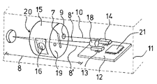
- FIG. 4 a principle representation of a IR gas sensor device
- FIG. 5 another principle representation of a IR gas sensor device with only one diode laser source.
- a laser source 1 provides a laser beam 2 passing through a cylindrical measuring chamber of, for example, 4 cm lengths and 0.5 cm diameter, thereby providing a basic longitudinal resonance.
- the chamber also comprises as usual a microphone 4 .
- the amplitude of the sound pressure is indicated by dotted line 5 .
- the resonance frequency of such an arrangement is approximately 4 kHz.
- the length of the chamber is for example 0.6 cm and the diameter 2 cm.
- This design provides sound pressure anti-nodes as lobes in 6 ′ on 6 ′′ in the upper and lower half of the chamber 3 ′.
- the resonance frequency of this design is approximately 10 kHz.
- FIG. 3 shows a front view of a detection chamber 3 ′ according to FIG. 2 , where the front and back sides are identical.
- the upper node 6 ′ and the lower node 6 ′′ enables an opening at the belt line of the measuring chamber 3 ′ as shown in this figure.
- the opening 7 along the belt line is used for gas inlet and outlet and for a laser beam for a TDLS measuring path 8 as shown in FIG. 4 .
- Opening 9 is used for the RPA measuring path 10 as shown in FIG. 4 .
- FIG. 4 shows the principle arrangement of the infrared gas sensor device with a housing 11 only indicated by dotted lines which includes an electronic board 12 on which are arranged a first tunable laser diode 13 , a second tunable laser diode 14 , a microprocessor 21 and other electronic components for the function of the device. Further shown is a measuring chamber 15 with a slot 7 on the front side 19 as well as on the back side 20 (not shown). The chamber 15 further comprises an opening 9 on the front side 19 faced to the second laser 14 .
- the reference number 16 refers to a port for a microphone adjacent the inner volume of the chamber 15 .
- the reflected laser beam 8 ′ travels again through the slots 7 back to a laser diode 18 arranged above the first laser source 13 .
- Second laser source 14 provides a laser beam 10 ′ which enters via opening 9 the measuring chamber 15 for exciting the gas volume inside the chamber 15 .
- FIG. 5 shows an arrangement with only one tunable diode laser source 22 which is multiplexed between two different beam generating conditions for providing either a laser beam for the TDLS measuring path or the RPA measuring path.
- Both laser beams enter the measuring chamber 15 ′ via the same opening 23 .
- the laser beam 8 ′ which is modulated for TDLS is reflected back by a mirror 17 ′ inside the housing 15 ′
- the other laser beam 10 ′ which is modulated for RPA detection only enters the opening 23 and excites the gas volume inside the chamber 15 ′.
- the RPA beam also generates upper node 6 ′ and lower node 6 ′′ of FIG. 3 since it enters the housing 15 ′ via the off-center opening 23 .
- TDLS and RPA detection can be performed on the same place in the housing 11 .
- the embodiment as shown is only for the purpose of explanation and not limited to the special design.
Landscapes
- Physics & Mathematics (AREA)
- Spectroscopy & Molecular Physics (AREA)
- General Health & Medical Sciences (AREA)
- Chemical & Material Sciences (AREA)
- Analytical Chemistry (AREA)
- Biochemistry (AREA)
- Life Sciences & Earth Sciences (AREA)
- General Physics & Mathematics (AREA)
- Immunology (AREA)
- Pathology (AREA)
- Health & Medical Sciences (AREA)
- Optics & Photonics (AREA)
- Investigating Or Analysing Materials By Optical Means (AREA)
Abstract
Description
Claims (22)
Applications Claiming Priority (2)
| Application Number | Priority Date | Filing Date | Title |
|---|---|---|---|
| EP07003553.0 | 2007-02-21 | ||
| EP07003553A EP1962077A1 (en) | 2007-02-21 | 2007-02-21 | Gas sensor |
Publications (2)
| Publication Number | Publication Date |
|---|---|
| US20080198364A1 US20080198364A1 (en) | 2008-08-21 |
| US7636153B2 true US7636153B2 (en) | 2009-12-22 |
Family
ID=38050026
Family Applications (1)
| Application Number | Title | Priority Date | Filing Date |
|---|---|---|---|
| US11/840,324 Active 2028-02-26 US7636153B2 (en) | 2007-02-21 | 2007-08-17 | Gas sensor |
Country Status (6)
| Country | Link |
|---|---|
| US (1) | US7636153B2 (en) |
| EP (1) | EP1962077A1 (en) |
| JP (1) | JP2008203248A (en) |
| KR (1) | KR20080077905A (en) |
| CN (1) | CN101251480B (en) |
| CA (1) | CA2621757A1 (en) |
Cited By (2)
| Publication number | Priority date | Publication date | Assignee | Title |
|---|---|---|---|---|
| US20090279094A1 (en) * | 2008-05-06 | 2009-11-12 | Drager Safety Ag & Co. Kgaa | Gas-measuring arrangement with an open optical measuring section |
| US20180003624A1 (en) * | 2014-12-17 | 2018-01-04 | Siemens Aktiengesellschaft | Absorption Spectrometer |
Families Citing this family (8)
| Publication number | Priority date | Publication date | Assignee | Title |
|---|---|---|---|---|
| EP2591383B1 (en) | 2010-07-08 | 2019-01-16 | Halliburton Energy Services, Inc. | Method and system of determining constituent components of a fluid sample in a downhole tool |
| US20120013472A1 (en) * | 2010-07-15 | 2012-01-19 | General Electric Company | Systems and Methods of Monitoring Combustible Gases in a Coal Supply |
| EP2770319B2 (en) | 2013-02-25 | 2022-01-26 | Sick Ag | Gas measuring device |
| US20150063408A1 (en) * | 2013-09-04 | 2015-03-05 | Decagon Devices, Inc. | Gaseous concentration measurement apparatus |
| CN103940777B (en) * | 2014-03-12 | 2016-02-03 | 重庆大学 | Portable inspectiont SF 6decomposition components infrared laser gas sensor |
| DE102014221029B4 (en) * | 2014-10-16 | 2023-03-30 | Syntegon Technology Gmbh | Monitoring unit for monitoring objects for pharmaceutical applications, in particular stoppers for containers |
| CN109490216B (en) * | 2019-01-07 | 2021-02-19 | 大连理工大学 | Calibration-free laser photoacoustic spectrum trace gas detection instrument and method |
| KR102269015B1 (en) * | 2019-11-08 | 2021-06-24 | (주)센서테크 | Acoustic Sensor for gas measurement |
Citations (9)
| Publication number | Priority date | Publication date | Assignee | Title |
|---|---|---|---|---|
| US3820901A (en) | 1973-03-06 | 1974-06-28 | Bell Telephone Labor Inc | Measurement of concentrations of components of a gaseous mixture |
| AU549570B2 (en) | 1981-04-13 | 1986-01-30 | Australian Atomic Energy Commission | Measuring the concentration of gaseous hydrogen fluoride |
| US4808828A (en) * | 1985-12-02 | 1989-02-28 | Hitachi, Ltd. | Method of and apparatus for simultaneous determination |
| US4871916A (en) | 1987-05-08 | 1989-10-03 | The Broken Hill Proprietary Company Limited | Sensing of methane |
| US5178836A (en) * | 1988-04-08 | 1993-01-12 | Hitachi, Ltd. | Analytical method for particulate substances, relevant analytical equipment and its application system |
| EP1154932A2 (en) | 1998-10-08 | 2001-11-21 | Pactiv Corporation | System and method of making a modified atmosphere package |
| US20030038237A1 (en) | 2001-08-21 | 2003-02-27 | Pranalytica, Inc. | Amplifier-enhanced optical analysis system and method |
| WO2005026705A1 (en) | 2003-09-12 | 2005-03-24 | Ir Microsystems S.A. | Gas detection method and gas detector device |
| US20050160800A1 (en) | 2004-01-28 | 2005-07-28 | Wolfgang Schindler | Measuring chamber for photo-acoustical sensors |
Family Cites Families (4)
| Publication number | Priority date | Publication date | Assignee | Title |
|---|---|---|---|---|
| GB2271181A (en) * | 1992-09-30 | 1994-04-06 | Marconi Gec Ltd | Photoacoustic Gas Analyser. |
| JP3537425B2 (en) * | 2002-03-29 | 2004-06-14 | 日本パステック株式会社 | Combined analyzer |
| CN1727875A (en) * | 2005-07-19 | 2006-02-01 | 大连理工大学 | Method for detecting density of hydrogen |
| CN2849712Y (en) * | 2005-12-22 | 2006-12-20 | 公安部上海消防研究所 | Apparatus based on photoacoustic principle for detecting toxic harmful gas and fire alarm |
-
2007
- 2007-02-21 EP EP07003553A patent/EP1962077A1/en not_active Withdrawn
- 2007-08-17 US US11/840,324 patent/US7636153B2/en active Active
-
2008
- 2008-01-09 KR KR1020080002375A patent/KR20080077905A/en not_active Application Discontinuation
- 2008-01-16 JP JP2008006702A patent/JP2008203248A/en active Pending
- 2008-02-19 CA CA002621757A patent/CA2621757A1/en not_active Abandoned
- 2008-02-20 CN CN2008100805965A patent/CN101251480B/en active Active
Patent Citations (9)
| Publication number | Priority date | Publication date | Assignee | Title |
|---|---|---|---|---|
| US3820901A (en) | 1973-03-06 | 1974-06-28 | Bell Telephone Labor Inc | Measurement of concentrations of components of a gaseous mixture |
| AU549570B2 (en) | 1981-04-13 | 1986-01-30 | Australian Atomic Energy Commission | Measuring the concentration of gaseous hydrogen fluoride |
| US4808828A (en) * | 1985-12-02 | 1989-02-28 | Hitachi, Ltd. | Method of and apparatus for simultaneous determination |
| US4871916A (en) | 1987-05-08 | 1989-10-03 | The Broken Hill Proprietary Company Limited | Sensing of methane |
| US5178836A (en) * | 1988-04-08 | 1993-01-12 | Hitachi, Ltd. | Analytical method for particulate substances, relevant analytical equipment and its application system |
| EP1154932A2 (en) | 1998-10-08 | 2001-11-21 | Pactiv Corporation | System and method of making a modified atmosphere package |
| US20030038237A1 (en) | 2001-08-21 | 2003-02-27 | Pranalytica, Inc. | Amplifier-enhanced optical analysis system and method |
| WO2005026705A1 (en) | 2003-09-12 | 2005-03-24 | Ir Microsystems S.A. | Gas detection method and gas detector device |
| US20050160800A1 (en) | 2004-01-28 | 2005-07-28 | Wolfgang Schindler | Measuring chamber for photo-acoustical sensors |
Non-Patent Citations (1)
| Title |
|---|
| European Search Report for corresponding Application No. 07 00 3553 dated Jun. 24, 2007. |
Cited By (4)
| Publication number | Priority date | Publication date | Assignee | Title |
|---|---|---|---|---|
| US20090279094A1 (en) * | 2008-05-06 | 2009-11-12 | Drager Safety Ag & Co. Kgaa | Gas-measuring arrangement with an open optical measuring section |
| US7884939B2 (en) * | 2008-05-06 | 2011-02-08 | Dräger Safety AG & Co. KGaA | Gas-measuring arrangement with an open optical measuring section |
| US20180003624A1 (en) * | 2014-12-17 | 2018-01-04 | Siemens Aktiengesellschaft | Absorption Spectrometer |
| US10132747B2 (en) * | 2014-12-17 | 2018-11-20 | Siemens Aktiengesellschaft | Absorption spectrometer |
Also Published As
| Publication number | Publication date |
|---|---|
| EP1962077A1 (en) | 2008-08-27 |
| KR20080077905A (en) | 2008-08-26 |
| CN101251480A (en) | 2008-08-27 |
| JP2008203248A (en) | 2008-09-04 |
| CA2621757A1 (en) | 2008-08-21 |
| CN101251480B (en) | 2011-11-23 |
| US20080198364A1 (en) | 2008-08-21 |
Similar Documents
| Publication | Publication Date | Title |
|---|---|---|
| US7636153B2 (en) | Gas sensor | |
| US10408745B2 (en) | Method and device for measuring the concentration of substances in gaseous or fluid media through optical spectroscopy using broadband light sources | |
| EP1750116B1 (en) | Gas concentration detection method and device | |
| US8334980B2 (en) | Integrated embedded processor based laser spectroscopic sensor | |
| CN101688827B (en) | Photo acoustic sample detector with light guide | |
| CA2540395A1 (en) | Method and device for detecting water vapor within natural gas | |
| US20180136166A1 (en) | Photoacoustic detector | |
| JP2009031282A (en) | Gas sensing method and gas sensor by performing quartz-enhanced photoacoustic spectroscopy | |
| WO2007004168A1 (en) | Photo-acoustic spectrometer apparatus | |
| US8848191B2 (en) | Photoacoustic sensor with mirror | |
| WO2009119790A1 (en) | Optical analyzer and wavelength stabilized laser device for analyzer | |
| JP6905992B2 (en) | Laser detection system and method | |
| CN106198449B (en) | A kind of other optical sensing device with explosion-resistant enclosure | |
| JP2009025298A (en) | Optical cavity system having orthogonal input | |
| US20040179200A1 (en) | Gas identification device | |
| US10876958B2 (en) | Gas-detecting device with very high sensitivity based on a Helmholtz resonator | |
| EP0518993B1 (en) | Method and apparatus for the transmission of an acoustic signal in a photoacoustic cell | |
| CN112924388A (en) | Orthogonal dual channel acoustic resonance module and device comprising same | |
| JP4766697B2 (en) | Small gas detector | |
| JP2008268064A (en) | Multicomponent responsive laser type gas analyzer | |
| Viveiros et al. | Ammonia sensing system based on wavelength modulation spectroscopy | |
| JP2007113948A (en) | Gas sensor | |
| Gong et al. | Scattering enhanced photoacoustic gas sensor based on acetate membrane | |
| US20240175804A1 (en) | Gas sensor for determining the concentration of at least one gas in a gas mixture and method for determining the concentration of at least one gas in a gas mixture with a gas sensor | |
| Bojęś et al. | Dual-band light-induced thermoelastic spectroscopy utilizing an antiresonant hollow-core fiber-based gas absorption cell |
Legal Events
| Date | Code | Title | Description |
|---|---|---|---|
| AS | Assignment |
Owner name: IR MICROSYSTEMS SA, SWITZERLAND Free format text: ASSIGNMENT OF ASSIGNORS INTEREST;ASSIGNORS:WILLING, BERT;KOHLI, MARKUS;SEIFERT, ANDREAS;REEL/FRAME:019715/0096 Effective date: 20070504 |
|
| STCF | Information on status: patent grant |
Free format text: PATENTED CASE |
|
| AS | Assignment |
Owner name: LEISTER PROCESS TECHNOLOGIES,SWITZERLAND Free format text: ASSIGNMENT OF ASSIGNORS INTEREST;ASSIGNOR:IR MICROSYSTEMS SA;REEL/FRAME:024079/0375 Effective date: 20100224 |
|
| AS | Assignment |
Owner name: AXETRIS AG, SWITZERLAND Free format text: ASSIGNMENT OF ASSIGNORS INTEREST;ASSIGNOR:LEISTER PROCESS TECHNOLOGIES;REEL/FRAME:027638/0541 Effective date: 20111212 |
|
| FPAY | Fee payment |
Year of fee payment: 4 |
|
| FEPP | Fee payment procedure |
Free format text: PAYOR NUMBER ASSIGNED (ORIGINAL EVENT CODE: ASPN); ENTITY STATUS OF PATENT OWNER: LARGE ENTITY |
|
| FPAY | Fee payment |
Year of fee payment: 8 |
|
| MAFP | Maintenance fee payment |
Free format text: PAYMENT OF MAINTENANCE FEE, 12TH YEAR, LARGE ENTITY (ORIGINAL EVENT CODE: M1553); ENTITY STATUS OF PATENT OWNER: LARGE ENTITY Year of fee payment: 12 |