US7551200B2 - Camera controller and zoom ratio control method for the camera controller - Google Patents
Camera controller and zoom ratio control method for the camera controller Download PDFInfo
- Publication number
- US7551200B2 US7551200B2 US10/599,195 US59919506A US7551200B2 US 7551200 B2 US7551200 B2 US 7551200B2 US 59919506 A US59919506 A US 59919506A US 7551200 B2 US7551200 B2 US 7551200B2
- Authority
- US
- United States
- Prior art keywords
- camera
- image
- zoom magnification
- switching
- section
- Prior art date
- Legal status (The legal status is an assumption and is not a legal conclusion. Google has not performed a legal analysis and makes no representation as to the accuracy of the status listed.)
- Active - Reinstated, expires
Links
Images


Classifications
-
- H—ELECTRICITY
- H04—ELECTRIC COMMUNICATION TECHNIQUE
- H04N—PICTORIAL COMMUNICATION, e.g. TELEVISION
- H04N23/00—Cameras or camera modules comprising electronic image sensors; Control thereof
- H04N23/60—Control of cameras or camera modules
- H04N23/66—Remote control of cameras or camera parts, e.g. by remote control devices
- H04N23/661—Transmitting camera control signals through networks, e.g. control via the Internet
-
- H—ELECTRICITY
- H04—ELECTRIC COMMUNICATION TECHNIQUE
- H04N—PICTORIAL COMMUNICATION, e.g. TELEVISION
- H04N7/00—Television systems
- H04N7/18—Closed-circuit television [CCTV] systems, i.e. systems in which the video signal is not broadcast
- H04N7/181—Closed-circuit television [CCTV] systems, i.e. systems in which the video signal is not broadcast for receiving images from a plurality of remote sources
-
- H—ELECTRICITY
- H04—ELECTRIC COMMUNICATION TECHNIQUE
- H04N—PICTORIAL COMMUNICATION, e.g. TELEVISION
- H04N23/00—Cameras or camera modules comprising electronic image sensors; Control thereof
- H04N23/60—Control of cameras or camera modules
- H04N23/63—Control of cameras or camera modules by using electronic viewfinders
- H04N23/633—Control of cameras or camera modules by using electronic viewfinders for displaying additional information relating to control or operation of the camera
-
- H—ELECTRICITY
- H04—ELECTRIC COMMUNICATION TECHNIQUE
- H04N—PICTORIAL COMMUNICATION, e.g. TELEVISION
- H04N23/00—Cameras or camera modules comprising electronic image sensors; Control thereof
- H04N23/60—Control of cameras or camera modules
- H04N23/69—Control of means for changing angle of the field of view, e.g. optical zoom objectives or electronic zooming
-
- H—ELECTRICITY
- H04—ELECTRIC COMMUNICATION TECHNIQUE
- H04N—PICTORIAL COMMUNICATION, e.g. TELEVISION
- H04N5/00—Details of television systems
- H04N5/222—Studio circuitry; Studio devices; Studio equipment
- H04N5/262—Studio circuits, e.g. for mixing, switching-over, change of character of image, other special effects ; Cameras specially adapted for the electronic generation of special effects
-
- H—ELECTRICITY
- H04—ELECTRIC COMMUNICATION TECHNIQUE
- H04N—PICTORIAL COMMUNICATION, e.g. TELEVISION
- H04N7/00—Television systems
- H04N7/18—Closed-circuit television [CCTV] systems, i.e. systems in which the video signal is not broadcast
- H04N7/188—Capturing isolated or intermittent images triggered by the occurrence of a predetermined event, e.g. an object reaching a predetermined position
Definitions
- the present invention relates to a camera control apparatus and a zoom magnification control method for this camera control apparatus, and particularly relates to camera control apparatus controlling a plurality of cameras and displaying one or a plurality of images of this plurality of cameras and a zoom magnification control method for this camera control apparatus.
- FIG. 1 A screen example for this typical remote monitoring system is shown in FIG. 1 .
- Screen 10 of a remote monitoring system shown in FIG. 1 is composed of image display region 11 that displays images for a plurality of remotely arranged cameras, camera select region 12 that selects a camera to display an image from the plurality of installed cameras, and camera control region 13 that controls the camera selected by camera select region 12 .
- the user observing the image can observe locations where the user wants to see from those displayed at camera select region 12 by clicking icon 14 so as to switch over between cameras.
- FIG. 2 A configuration for this kind of remote monitoring system is shown in FIG. 2 .
- the remote monitoring system shown in FIG. 2 is composed of a plurality of cameras 20 a to 20 n installed remotely, camera control apparatus 21 that receives and plays back images from cameras 20 a to 20 n and controls the photographing direction and zoom magnification etc. of cameras 20 a to 20 n , monitor 22 that displays camera images, and pointing device 23 such as a mouse etc. that controls cameras 20 a to 20 n and instructs images for display.
- Camera control apparatus 21 is configured from camera image switching section 24 that receives images from the plurality of cameras 20 a to 20 n and switches images by instructions from the user, image display section 25 that displays images of cameras 20 a to 20 n at monitor 22 , camera control instruction receiving section 26 switching camera images to be displayed and receiving instructions from a user for controlling photographing direction and zoom magnification of a camera, and camera control section 27 that instructs for controlling to cameras 20 a to 20 n and that instructs for switching of images to be displayed at camera image switching section 24 .
- a user designates cameras 20 a to 20 n which the user wants to observe from the plurality of cameras 20 a to 20 n from camera select region 12 shown in FIG. 1 by pointing device 23 .
- camera control instruction receiving section 26 then receives a control instruction from a user and reports the instruction to camera control section 27 .
- Camera control section 27 stores that an instruction for camera control received from camera control instruction receiving section 26 is for a camera designated by a user, and instructs switching of an image of a camera displayed at monitor 22 to camera image switching section 24 .
- Camera image switching section 24 sends an image for which an instruction is received from camera control section 27 to image display section 25 and image display section 25 displays this image at monitor 22 .
- FIG. 1 is for the case of a configuration displaying just one image for a camera of the images for the plurality of cameras 20 a to 20 n but monitoring systems displaying a plurality of camera images at the same time also exist, as shown in FIG. 3 .
- This kind of display method has the drawback that it is not possible to observe detailed portions of the image because the display region for an image for each one camera is small.
- the camera control apparatus shown in FIG. 4 includes map 40 that displays icons at locations where cameras are installed, image display region 42 that displays the selected camera image, and camera control region 43 that controls the selected camera.
- Icon 41 on map 40 displaying the d photographing direction and field of view of the camera is selected, and a user can then display an image which the user wants to see by controlling a straight line indicating a boundary line of the Field of view and a photographing direction of the camera by a pointing device.
- FIG. 5 is an outline view showing the state of a camera image before and after switching at the time of switching over cameras by the method of the related art.
- FIG. 5A shows the state of a camera image before switching
- FIG. 5B shows a camera image at the moment that the image is switched to the instructed camera as a result of a user clicking on icon 50 by a pointing device etc.
- Patent Document 1 Japanese Patent Application Laid-Open No. HEI9-289607.
- the photographing direction for individual cameras changes as time goes by as a result of a plurality of users accessing the respective cameras and controlling the cameras. It is therefore difficult for a user to intuitively determine which direction a camera is facing in when moving the line of view at the moment of viewing another camera image.
- Camera control apparatus of the present invention adopts a configuration where camera control apparatus controlling a plurality of cameras and displaying one or a plurality of images of the plurality of cameras comprises an image switching section that switches over to an image of a camera instructed to be switched over to by a user, a zoom magnification control section that acquires zoom magnification of the camera instructed to be switched over to, changes the zoom magnification of the camera to a reference magnification lower than the acquired zoom magnification before switching of the image switching section, and changes zoom magnification of the camera after switching from the reference magnification to the acquired zoom magnification, and an image display section that displays an image of the camera the image switching section switches over to.
- a user when an image is switched over, a user can intuitively understand the photographing direction and zoom magnification of a camera so that it is possible for a user to start control of a camera for observing an image immediately.
- FIG. 1 shows a display example of a screen displaying a camera control apparatus of the related art
- FIG. 2 is a block view showing a configuration or a camera control apparatus of the related art
- FIG. 3 shows a display example of a plurality of screens displayed at the same time by camera control apparatus of the related art
- FIG. 4 shows a display example where a camera control apparatus of the related art displays camera images and camera installation positions at the same time
- FIG. 5 shows display examples of a screen for before and after camera switching at a camera control apparatus of the related art
- FIG. 6 is a block view showing a configuration of a camera control apparatus according to Embodiment 1 of the present invention.
- FIG. 7 shows a display example of a monitor according to Embodiment 1 of the present invention.
- FIG. 8 is a flow chart showing the flow of a camera control operation of a camera control apparatus according to Embodiment 1 of the present invention.
- FIG. 9 shows examples of a way of changing a screen when a camera control apparatus according to Embodiment 1 of the present invention switches cameras;
- FIG. 10 shows a configuration of a camera control apparatus changing the speed of change of zoom magnification according to Embodiment 1 of the present invention
- FIG. 11 is a block view showing a configuration for camera control apparatus displaying a control state of a camera according to Embodiment 1 of the present invention.
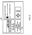
- FIG. 12 shows a display example of a message displayed by a camera control apparatus according to Embodiment 1 of the present invention.
- FIG. 13 is a block view showing a configuration of a camera control apparatus according to Embodiment 2 of the present invention.
- FIG. 14 is a flow chart showing the flow of a camera control operation of a camera control apparatus according to Embodiment 2 of the present invention.
- FIG. 15 shows directions of rotation of a camera of a camera control apparatus according to Embodiment 2 of the present invention
- FIG. 16 illustrates a method for calculating zoom magnification of a camera of a camera control apparatus according to Embodiment 2 of the present invention
- FIG. 17 shows examples of a way of changing a screen when a camera control apparatus according to Embodiment 2 of the present invention switches cameras;
- FIG. 18 shows a display example of a message when an image of a camera control apparatus according to Embodiment 2 of the present invention is changed over;
- FIG. 19 is a flow chart showing the flow of a camera control operation in the case of the camera control apparatus according to Embodiment 2 of the present invention controlling a camera after to switching;
- FIG. 20 is a block view showing a configuration of a camera control apparatus displaying a control state of a camera according to Embodiment 2;
- FIG. 21 is a block view showing an example of a configuration of a camera control apparatus according to Embodiment 3 of the present invention.
- FIG. 22 is a flow chart showing the flow of a camera control operation of a camera control apparatus according to Embodiment 3 of the present invention.
- FIG. 23 is a flow chart illustrating the flow of zoom magnification optimization processing according to Embodiment 3 of the present invention.
- FIG. 24 is a block view showing an example of a configuration of a camera control apparatus according to Embodiment 4 of the present invention.
- FIG. 25 is a flow chart showing the flow of a camera control operation of a camera control apparatus according to Embodiment 4 of the present invention.
- FIG. 26 is a flow chart illustrating the flow of zoom magnification optimization processing according to Embodiment 4 of the present invention.
- FIG. 27 illustrates a landmark position calculating method according to Embodiment 4 of the present invention
- FIG. 28 illustrates a landmark determination method according to Embodiment 4 of the present invention.
- FIG. 29 is a block view showing an example of a configuration of a camera control apparatus according to Embodiment 5 of the present invention.
- FIG. 30 is a flow chart showing the flow of a camera control operation of a camera control apparatus according to Embodiment 5 of the present invention.
- FIG. 31 is a flowchart illustrating switching image generation processing of a camera control apparatus according to Embodiment 5 of the present invention.
- FIG. 32 illustrates switched images generated by the camera control apparatus according to Embodiment 5 of the present invention.
- FIG. 33 shows an example of a configuration where switching image generation apparatus according to Embodiment 5 of the present invention are connected via camera control apparatus and a network;
- FIG. 34 shows an example of a configuration of switching image generation apparatus of FIG. 33 .
- FIG. 6 is a configuration view showing an example of a remote monitoring system containing a camera control apparatus according to Embodiment 1 of the present invention.
- This remote monitoring system has a plurality of remotely installed cameras 100 a to 100 n , camera control apparatus 120 that receives and plays images from cameras 100 a to 100 n and controls the photographing direction and zoom magnification etc of cameras 100 a to loon, monitor 130 that displays camera images sent from camera control apparatus 120 , and pointing device 140 such as a mouse etc. that instructs control of and images to be displayed for cameras 100 a to loon at camera control apparatus 120 .
- cameras 100 a to 100 n , monitor 130 and pointing device 140 are, for example, connected to camera control apparatus 120 via a network such as, for example, the Internet.
- camera control apparatus 120 has camera image switching section 121 that switches one or a plurality of images of the plurality of remotely installed cameras 100 a to 100 n , image display section 122 that displays images switched over to by camera image switching section 12 ′, camera control instruction receiving section 123 that receives instructions of pointing device 140 , camera control information transmitting/receiving section 124 that instructs camera 100 a to loon to control photographing direction and zoom magnification of the cameras, and inquires about and receives current photographing angle, photographing direction and zoom magnification etc. of cameras 100 a to 100 n , zoom magnification adjustment section 125 that decides zoom magnification of cameras 100 a to 100 n , and zoom magnification storage section 126 that stores zoom magnification of cameras 100 a to 100 n.
- Camera control apparatus 120 receives images for the plurality of cameras 100 a to 100 n and displays an image or one of these cameras at monitor 130 .
- the camera image displayed at monitor 130 is designated by pointing device 140 of a mouse etc. connected to camera control apparatus 120 .
- camera control apparatus 120 sends a camera control signal controlling the camera to the camera instructed for display by pointing device 140 .
- Photographing direction zoom control equipments 110 a to 110 n connected to cameras 100 a to 100 n receive camera control signals sent from camera control apparatus 120 and control the photographing point, photographing direction, and zoom magnification of cameras 100 a to 100 n.
- FIG. 7 examples of a camera image and a camera control icon displayed at monitor 130 are shown in FIG. 7 .
- Image display region 210 , camera designation region 220 , and camera control icon display region 230 are displayed at monitor 13 .
- FIG. 7 an example is shown where an image for one camera of the plurality of installed cameras 100 a to loon is displayed at image display region 210 , but images for a plurality of or all of the cameras 100 a to 100 n may be displayed.
- a description of the locations where the plurality of cameras are installed and icons 221 designating the cameras are displayed on camera designation region 220 .
- the user designating and controlling the cameras by looking at the monitor selects cameras 100 a to 100 n for displaying images by clicking this icon 221 with pointing device 140 . Further, the user can control cameras 100 a to 100 n designated by the icon 221 using up, down, left and right, and zoom in and zoom out icons displayed at camera control icon display region 230 .
- FIG. 8 is a flow chart showing the flow of a camera control operation of camera control apparatus 120 when a camera image switching instruction is given by the user in this embodiment.
- camera control information transmitting/receiving section 124 inquires photographing direction zoom magnification control equipment 110 connected to the cameras about the current zoom magnification of the camera instructed by the user (step S 301 ). Upon receiving the current zoom magnification of the camera from photographing direction zoom magnification control equipment 110 , camera control information transmitting/receiving section 124 makes this zoom magnification to store in zoom magnification storage section 126 (step S 302 ) upon completing storage of the zoom magnification, zoom magnification storage section 126 informs zoom magnification adjustment section 125 that storage is complete.
- Zoom magnification adjustment section 125 then sends a zoom magnification adjustment instruction to photographing direction zoom magnification control equipment 110 connected to the camera via camera control information transmitting/receiving section 124 so as to put the zoom magnification of the camera from the zoom magnification stored in zoom magnification storage section 126 to the widest angle zoom magnification at the point where storage of zoom magnification from zoom magnification storage section 126 is complete (step S 303 ).
- the widest angle zoom magnification is such that, for example, zoom magnification adjustment section 125 stores the operating range for the zoom magnification of the camera in advance during installation of the cameras, or camera control information transmitting/receiving section 124 acquires the operation range of the zoom magnification of the camera at the same time in addition to the current zoom magnification of the camera from photographing direction zoom magnification control equipment 110 as a response to the inquiry to the cameras about the zoom magnification.
- photographing direction zoom magnification control equipment 110 completes adjustment of the zoom magnification of the camera designated by camera control information transmitting/receiving section 124
- photographing direction zoom magnification control equipment 110 connected to the camera reports camera control information transmitting/receiving section 124 that adjustment of the zoom magnification is complete.
- camera control information transmitting/receiving section 124 instructs camera image switching section 121 to switch over of the camera image (step S 304 ).
- the image displayed at monitor 130 via image display section 122 is switched over to the image designated by the user.
- camera image switching section 121 reports zoom magnification adjustment section 125 that image switching is complete.
- zoom magnification adjustment section 125 Upon receiving report that switching over of the images is complete from camera image switching section 121 , zoom magnification adjustment section 125 inquires about the zoom magnification prior to the widening of the camera zoom magnification stored in zoom magnification storage section 126 . Zoom magnification adjustment section 125 controls the camera via camera control information transmitting/receiving section 124 in such a manner that the zoom magnification of the camera photographing at the widest angle zoom magnification is changed to the zoom magnification before making the angle wide (step S 305 ).
- zoom magnification adjustment section 125 sends a control signal to photographing direction zoom magnification control equipment 110 connected to the camera after switching via camera control information transmitting/receiving section 124 in such a manner that the zoom magnification of the camera after switching returns to the zoom magnification stored in zoom magnification storage section 126 by camera control information transmitting/receiving section 124 in step S 302 .
- camera control apparatus 120 is capable of controlling the zoom magnification of the cameras instructed to be switched over to at the time switching of a camera image is instructed by a user.
- zoom magnification adjustment section 125 only has to change the zoom magnification by just a predetermined range to a wide angle, i.e. to a low magnification to the extent that the user intuitively understands the photographing direction and zoom magnification of the camera and where the image for the camera is being photographed for simply by looking at the image of the camera after switching over.
- camera control instruction receiving section 123 receives a switching instruction for cameras 100 a to 100 n from a user
- camera control information transmitting/receiving section 124 acquires the current zoom magnification for the camera instructed to be switched over to
- zoom magnification storage section 126 stores the zoom magnification for the camera acquired by camera control information transmitting/receiving section 124 .
- Zoom magnification adjustment section 125 then changes the zoom magnification of the camera instructed to be switched over to from the zoom magnification of the camera stored by zoom magnification storage section 126 to a wide angle state, i.e. to a desired zoom magnification lower than the stored zoom magnification.
- zoom magnification adjustment section 125 returns the zoom magnification of the camera changed to a wide angle to the zoom magnification stored by zoom magnification storage section 126 .
- FIG. 9 shows an example of a screen displayed at monitor 130 when camera control apparatus 120 of this embodiment switches over camera images.
- FIG. 9A is an example screen of monitor 130 before camera image switching is instructed by a user.
- the user designates camera image switching by clicking icon 401 that displays the installation position of she camera displaying the desired image by pointing device 140 .
- camera control apparatus 120 controls zoom magnification of the camera designated by the user with the flow described above
- FIG. 9C shows a display example of a camera image at the time of switching the camera image in step S 304 of FIG. 8 . At this time, an image of the camera designated by the user in FIG.
- the zoom magnification of the camera is adjusted to be photographed at the widest angle.
- the magnification of the camera image taken at the widest angle shown in FIG. 9C is zoomed up, and the zoom magnification state of the camera is returned to the zoom magnification when the user instructs switching of the camera.
- the zoom magnification is returned to the zoom magnification stored by zoom magnification storage section 126 as shown in step S 302 of FIG. 8 .
- the user can intuitively determine the photographing direction and zoom magnification the camera instructed to be switched over to is photographing in from the camera image.
- zoom magnification adjustment section 125 can adjust the speed for changing the zoom magnification based on the frame rate of the camera image displayed at monitor 130 . Namely, zoom magnification adjustment section 125 may be adjusted to show smooth movement of zoom magnification adjustment from FIG. 9C to FIG. 9D .
- the configuration of camera control apparatus 120 in this case is the configuration shown in FIG. 10 .
- the configuration of camera control apparatus 120 shown in FIG. 10 is for transmitting frame rate information of the image displayed by image display section 122 of camera control apparatus 120 shown in FIG. 6 to zoom magnification adjustment section 125 and other aspects of the configuration are the same as for the configuration of FIG. 6 .
- camera image switching section 121 reports zoom magnification adjustment section 125 of image frames being received from cameras 100 a to 100 n and zoom magnification adjustment section 125 acquires frame rate information from image frames received from camera image switching section 121 .
- frame rate Information displayed by image display section 122 is sent to zoom magnification adjustment section 125 , and zoom magnification adjustment section 125 may then acquire the frame rate information received from image display section 122 .
- the processing method for adjusting the change in speed of the zoom magnification by zoom magnification adjustment section 125 referring to the frame rate of the image displayed at monitor 130 does not change.
- zoom magnification adjustment section 125 changes the speed for adjusting the zoom magnification by referring to the frame rate of the image displayed at monitor 130 .
- the frame rate of the image received by camera image switching section 121 or the frame rate of the image displayed by image display section 122 at monitor 130 is taken to be Nfps.
- fps is an abbreviation of frames per second, and is the number of image frames that can be displayed in one second.
- the speed for changing the zoom magnification for the camera by zoom magnification adjustment section 125 is different according to whether the user looking at the image wants to operate the camera soon or whether the user wants to observe the adjustment of the zoom magnification more smoothly. In Embodiment 1, however, a description is given where the zoom magnification is increased M times every time the image frame changes so as to realize smooth movement.
- camera control apparatus 120 may also show the user that the camera is being automatically controlled after switching.
- Camera control apparatus 120 in this case adopts the configuration shown in FIG. 11 .
- the configuration of camera control apparatus 120 shown in FIG. 11 is the configuration of camera control apparatus 120 shown in FIG. 6 with camera control information display section 601 added, with other aspects of the configuration being the same as for the configuration of FIG. 6 .
- camera control information display section 601 displays that the zoom magnification of the camera after switching has been returned to the zoom magnification stored by zoom magnification storage section 126 at monitor 130 via camera control information transmitting/receiving section 124 .
- This example is shown in FIG. 12 .
- message 701 to the effect of “zoom magnification is being controlled” is displayed at monitor 130 indicating that zoom magnification of the camera after switching by camera control apparatus 120 is being changed.
- the method and location for displaying the message is not limited to that described here, and any method may be possible if the display is shown in such a manner that the user can understand that the zoom magnification of the camera after switching is being moved automatically without the intervention of the user.
- Embodiment 1 in the event that a user switches over a camera image to be displayed, it is possible for the user to intuitively understand the installation position, photographing direction and zoom magnification of the camera simply by looking at the image as a result of zoom magnification adjustment section 125 returning zoom magnification of the camera from the widest angle to the zoom magnification when the user selects the camera image.
- zoom magnification adjustment section 125 In Embodiment 1, a description is given where the zoom magnification adjusted by zoom magnification adjustment section 125 is taken to be at the widest angle but the present invention is not limited to this. Namely zoom magnification adjustment section 125 therefore only has to change the zoom magnification to a wide angle, i.e. to a low magnification to the extent that the user intuitively understands the photographing direction and zoom magnification of the camera simply by looking at the image of the camera and where the image for the camera is being photographed after switching.
- zoom magnification adjustment section 125 changes the zoom magnification of the camera to a zoom magnification of an angle wider than the magnification stored in storage section 126 , i.e. to a reference magnification lower than the stored zoom magnification before switching to the image of the camera instructed to be switched over to by the user by camera image switching section 121 .
- zoom magnification adjustment section 125 After switching over camera image, as a result of zoom magnification adjustment section 125 returning the zoom magnification of the camera from the reference magnification to the zoom magnification stored by zoom magnification storage section 126 , it is possible for a user to intuitively understand the photographing direction and zoom magnification of the camera by looking at the image, and a so to start control of the camera immediately in the event of chancing to a desired photographing direction and zoom magnification.
- FIG. 13 A configuration view of camera control apparatus 120 of Embodiment 2 of the present invention is shown in FIG. 13 .
- Camera control apparatus 120 of FIG. 13 has also added photographing direction adjustment section 801 enabling control of photographing direction to camera control apparatus 120 of FIG. 6 in addition to the zoom magnification of the camera, and has photographing direction zoom magnification storage section 802 capable of also storing photographing direction in addition to camera zoom magnification instead of zoom magnification storage section 126 .
- Other components are the same as for camera control apparatus 120 of Embodiment 1 shown in FIG. 6 so that the same components are assigned the same reference numerals, and the detailed descriptions thereof will be omitted.
- the configuration of the screen displayed at monitor 130 is also the same as for Embodiment 1.
- camera control information transmitting/receiving section 124 inquires photographing direction zoom magnification control equipments 110 a to 110 n connected to cameras 100 a to 100 n about the current zoom magnification of the camera instructed by the user. Camera control information transmitting/receiving section 124 then receives this zoom magnification and stores this in photographing direction zoom magnification storage section 802 . Photographing direction zoom magnification storage section 802 then stores the zoom magnification received from camera control information transmitting/receiving section 124 .
- zoom magnification adjustment section 125 changes the zoom magnification of the camera instructed to be switched over to by the user from the stored zoom magnification to the widest angle zoom magnification, and controls the zoom magnification of this camera via camera control information transmitting/receiving section 124 .
- the flow of this operation corresponds to step S 301 to step S 303 of FIG. 8 .
- zoom magnification adjustment section 125 changes zoom magnification of the camera after switching, i.e.
- photographing direction adjustment section 801 automatically controls the photographing direction of the camera before switching to be as close as possible to the photographing position and photographing range of the camera after switching, i.e. the camera that received switching instructions from the user.
- zoom magnification adjustment section 125 changes zoom magnification of the camera after switching, i.e. the camera instructed to be switched over to by the user, from the stored zoom magnification to a zoom magnification capable of the widest angle photographing
- camera control information transmitting/receiving section 124 inquires photographing direction zoom magnification control equipment 110 connected to the camera about the photographing direction, field angle, and focus distance of the camera after switching where the zoom magnification is changed to the widest angle (step S 901 ).
- photographing direction represents the pan and tilt angle of the camera.
- field angle is a value obtained from individual performances and zoom magnification of the camera.
- camera control information transmitting/receiving section 124 Upon receiving information for pan and tilt angle, field angle, and focus distance, camera control information transmitting/receiving section 124 stores this information in photographing direction zoom magnification storage section 802 (step S 902 ). If photographing direction zoom magnification storage section 802 has completed storage of information for the pan and tilt angle, the field angle and focus distance, photographing direction adjustment section 801 calculates the direction and field angle the camera before switching is to be rotated by from information for the pan and tilt angle, field angle and focus distance stored by photographing direction zoom magnification storage section 802 and the installation position of the camera before switching (step S 903 ).
- the installation position of the camera before switching is stored in photographing direction adjustment section 801 at the time the camera before switching is installed, or photographing direction zoom magnification control equipments 100 a to 100 n of the individual cameras 100 a to 100 n may store installation positions in advance, so that, for example, camera control information transmitting/receiving section 124 separately inquires and acquires the installation positions from cameras 100 a to loon before switching when camera image instruction is given from a user.
- FIG. 15A and FIG. 15B show coordinates for cameras before switching and for cameras after switching in the same coordinate plane as viewed from mid-air towards ground.
- the pan angle of camera 1001 before switching is taken to be 1003
- the pan angle of camera 1002 after switching is taken to be 1004
- a focal point of camera 1002 after switching is taken to be 1005 .
- Camera control information transmitting/receiving section 124 has already obtained the coordinates of camera 1001 before switching, the coordinates of camera 1002 after switching, and angle of rotation 1004 of camera 1002 after switching in processing up to this point (step S 902 of FIG. 14 ).
- coordinates of camera 1001 before switching are taken to be (x 1 , y 1 ) coordinates of camera 1002 after switching are taken to be (x 2 , y 2 ), and rotational angle 1004 of the camera after switching is taken to be ⁇ 2 .
- photographing direction adjustment section 801 controls the photographing direction of camera 1001 before switching in such a manner that the photographing direction of camera 1001 before switching faces focal point 1005 of camera 1002 .
- Photographing direction adjustment section 801 then controls the photographing direction of camera 1001 before switching via camera control information transmitting/receiving section 124 in such a manner that the photographing direction of camera 1001 before switching becomes the angle ⁇ 1f .
- the photographing direction of the camera before switching is therefore close to the photographing direction of the camera after switching, i.e. close to the image of the camera after switching. Therefore, in the event that the camera is switched over to, a sense of discomfort felt by a user at the time of looking at an image after switching can be reduced, and it is possible for the user to intuitively understand the photographing position and photographing direction of the camera just by looking at this image.
- FIG. 16 a method for calculating field angle of a camera before switching is shown in FIG. 16 .
- field angle 1103 of camera 1001 before switching is adjusted in such a manner that photographing range 1102 of camera 1002 after switching at the time where camera 1001 before switching and camera 1002 after switching are photographing the same point and photographing range 1101 of camera 1001 before switching become the same length.
- Field angle ⁇ 2g of camera 1002 after switching has already been acquired by camera control information transmitting/receiving section 124 (step S 902 of FIG. 14 ), and length len of photographing range 1102 of the camera after switching can be expressed by the following equation (4).
- equation (4) is substituted in equation (5) to give the following equation (6).
- Photographing direction adjustment section 801 adjusts the field angle of camera 1001 before switching to ⁇ 1g expressed by the above equation (6).
- the magnification of the camera before switching is therefore close to the magnification of the camera after switching, i.e. close to the photographing range of the camera after switching. Therefore, in the event that the camera is switched, a sense of discomfort felt by a user at the time of looking at an image after switching can be reduced, and it is possible for the user to intuitively understand the photographing position, photographing direction, and photographing range etc. of the camera just by looking at this image after switching.
- Photographing direction adjustment section 801 controls the camera before switching via camera control information transmitting/receiving section 124 in such a manner as to give the camera photographing direction and zoom magnification of the camera before switching calculated from the flow described above (step S 904 ).
- camera control information transmitting/receiving section 124 instructs switching of the image displayed at monitor 130 to camera image switching section 121 (step S 905 ).
- the flow for returning the zoom magnification of the camera after switching i.e. returning to the zoom magnification stored in photographing direction zoom magnification storage section 802 is the same as for the case in Embodiment 1. This corresponds to step S 305 in the drawings of the flow of FIG. 8 .
- camera control apparatus 120 automatically controls the camera photographing the image before switching and the camera after switching over designated by the user.
- FIG. 17 is a view showing a display example of an image displayed at monitor 130 when the camera before switching and the camera after switching are controlled respectively in this embodiment.
- a camera image before switching is displayed in FIG. 17A .
- the screen goes from this state to the screen 1202 shown in FIG. 17B .
- photographing direction adjustment section 801 changes the photographing direction and zoom magnification in such a manner that the camera photographing images displayed up to this point, i.e. the camera before switching is as close as possible to the field of view of the camera after switching.
- FIG. 17C the image of the camera designated by the user is switched over to.
- switching of the camera may be proposed to the user by a pop-up window by displaying, for example, message 1301 to the effect of “the image has been switched”.
- the operation of controlling the cameras before switching and after switching is completed by returning the zoom magnification to the original magnification.
- photographing direction zoom magnification storage section 802 may store the photographing direction and zoom magnification of a camera before switching, so that after completion of switching of the camera, photographing direction adjustment section 901 returns the photographing direction and zoom magnification of the camera before switching to the original photographing direction and zoom magnification stored in photographing direction zoom magnification storage section 802 .
- photographing direction adjustment section 801 returns the field of view of the camera after switching to the photographing direction and zoom magnification stored by photographing direction zoom magnification storage section 802 .
- the configuration of the camera control apparatus in this case is substantially the same as the configuration of camera control apparatus 120 of FIG. 8 , but differs in that photographing direction zoom magnification storage section 802 stores photographing direction of the camera before switching, zoom magnification and focus distance, and photographing direction and zoom magnification of the camera after switching, and photographing direction adjustment section 801 operates for controlling in such a manner that the field of view of the camera after switching matches with the field of view of the camera before switching.
- camera control information transmitting/receiving section 124 inquires photographing direction zoom magnification control equipment 110 connected to the cameras about the photographing direction and zoom magnification of the camera before switching the camera after switching, i.e. of the camera instructed to be switched over to by the user, and stores the acquired photographing direction and zoom magnification in photographing direction zoom magnification storage section 802 (step S 1401 ).
- photographing direction zoom magnification storage section 802 also stores the focus distance of the camera before switching.
- photographing direction adjustment section 801 controls the camera after switching in such a manner that the photographing direction and zoom magnification of the camera after switching is similar to the image of the camera before switching (step S 1402 ).
- the method for calculating the photographing direction and zoom magnification of the camera is the same as the method described Embodiment 2.
- camera control information transmitting/receiving section 124 instructs image switching to camera image switching section 121 and switches over the image (step S 1403 ).
- photographing direction adjustment section 801 Upon completing switching of the image, photographing direction adjustment section 801 receives report that switching of the image is complete from camera image switching section 121 and performs control in such a manner that the photographing direction and zoom magnification of the camera after switching returns to the photographing direction and zoom magnification stored by photographing direction zoom magnification storage section 802 in step S 1401 (step S 1404 ).
- photographing direction adjustment section 801 performs control so that the image of the camera before switching and the image of the camera after switching are made to be close to each other.
- camera control apparatus 120 may also display that the camera before switching and the camera after switching are being controlled automatically.
- the configuration in this case is shown in FIG. 20
- the configuration of camera control apparatus 120 shown in FIG. 20 is the configuration of camera control apparatus 120 shown in FIG. 13 with camera control information display section 601 of FIG. 11 added, and other aspects of the configuration are the same as for the configuration of FIG. 13 .
- camera control information display section 601 displays that the zoom magnification of the camera after switching has been returned to the zoom magnification stored by photographing direction zoom magnification storage section 802 at monitor 130 via camera control information transmitting/receiving section 124 .
- automatic control of the zoom magnification of the camera after switching by camera control apparatus 120 of Embodiment 2 may be proposed to the user by a message 701 etc. to the effect of, for example, “zoom magnification is being controlled”.
- this embodiment may adopt a configuration where the frame rate of an image received by camera image switching section 121 as in Embodiment 1 or the frame rate of the image displayed by image display section 122 is referred to, and the photographing direction adjustment section 801 adjusts the speed for changing the zoom magnification and camera photographing direction of the camera before switching.
- the photographing direction adjustment section 801 adjusts the speed for changing the zoom magnification and camera photographing direction of the camera before switching.
- photographing direction adjustment section 801 exerts control in such a manner that the photographing direction and zoom magnification of the camera that displayed the image before selection by the user are made to be the same as the photographing position and photographing range of the camera after switching to as great an extent as possible. It is therefore possible for the user to understand the installation position, photographing direction and zoom magnification of the selected camera more intuitively by looking at this image directly after the image is switched over.
- photographing direction adjustment section 801 makes the photographing direction and photographing range of the camera before switching close to the photographing direction and photographing range of the camera after switching. It is therefore possible for the user to intuitively and instantly understand the photographing position, photographing direction and photographing range of the camera simply by looking at the image after switching.
- zoom magnification adjustment section 125 only has to change the zoom magnification to a wide angle, i.e. to a low magnification, to the extent that the user intuitively understands the photographing direction and zoom magnification of the camera simply by looking at the image of the camera and where the image for the camera is being photographed after switching.
- zoom magnification adjustment section 125 changes the zoom magnification of the camera to a zoom magnification of an angle wider than the magnification stored in storage section 126 before switching to the image of the camera instructed to be switched over to by the user by camera image switching section 121 , i.e. to a reference magnification lower than the stored zoom magnification.
- Photographing direction adjustment section 801 acquires photographing direction information specifying the photographing direction of the image of the camera instructed to be switched over to and photographing range information specifying the photographing range.
- Photographing direction adjustment section 801 then changes the photographing direction and photographing range of the image of the camera currently being displayed at image display section 121 to be as close as possible to being the same as the photographing direction and photographing range of the image of the camera before switching.
- zoom magnification adjustment section 125 returning the zoom magnification of the camera from the reference magnification to the zoom magnification stored by zoom magnification storage section 126 , it is possible for a user to understand the photographing position, photographing direction and zoom magnification of the camera more intuitively by looking at the image, and also to start control of the camera immediately in the event of changing to a desired photographing direction and zoom magnification.
- Camera control apparatus 120 of Embodiment 1 is described as making the zoom magnification the widest angle after storing the zoom magnification of the camera instructed to be switched over to in the event that camera image switching instruction is given from a user.
- Camera control apparatus 120 of Embodiment 3 of the present invention performs optimization processing for changing magnification making the zoom magnification the widest angle using landmark image information which specifies the photographing position and the photographing direction of the camera after switching.
- FIG. 21 A configuration view of camera control apparatus 120 of Embodiment 3 of the present invention is shown in FIG. 21 .
- camera control apparatus 120 of FIG. 21 has landmark registration section 2101 that registers image information for a landmark existing within the photographing range of each camera and specifying the photographing position and photographing direction of cameras, and landmark recognition section 2102 that determines whether or not image information for a landmark exists within an image of a camera after switching.
- landmark registration section 2101 that registers image information for a landmark existing within the photographing range of each camera and specifying the photographing position and photographing direction of cameras
- landmark recognition section 2102 that determines whether or not image information for a landmark exists within an image of a camera after switching.
- Other aspects of the configuration are the same as for camera control apparatus 120 of Embodiment 1 shown in FIG. 6 so that the same aspects of the configuration are assigned the same reference numerals, and detailed descriptions thereof will be omitted.
- FIG. 22 is a flow chart illustrating the camera control operation of camera control apparatus 120 of this embodiment.
- FIG. 22 differs only in that step S 2201 is different to step S 303 of FIG. 8 with other aspects of the operation being the same as for FIG. 8 so that the same components are assigned the same reference numerals, and detailed descriptions thereof will be omitted.
- zoom magnification adjustment section 125 performs optimization processing for the zoom magnification of the camera after switching based on the determination results of landmark recognition section 2102 in step S 2201 , instead of making the zoom magnification of the camera after switching the widest angle.
- Camera control apparatus 120 then moves to the operation of step S 304 onwards.
- FIG. 23 is a flow chart illustrating an example of optimization processing for zoom magnification of the camera after switching.
- a user or system administrator designates a landmark of an object etc. by pointing device 140 and extracts a template for image information for the landmark.
- landmarks are items existing within the photographing range of each of the cameras 100 a to 100 n that specify the photographing position or photographing direction of a camera and may be, for example, a construction such as a building etc. having a characteristic height, shape, and color, etc.
- Landmark registration section 2101 registers a template of image information for the template to landmark as landmark image information and provides this to landmark recognition section 2102 (step S 2301 ).
- This landmark image information is information for determining whether or not the landmark is in an image of a camera instructed to be switched over to, and specifically refers to the landmark image itself, color, brightness, shape, and edge information etc.
- Landmark recognition section 2102 receives an image of a camera instructed to be switched over to constituting a target for detection of the presence or absence of a landmark from camera image switching section 121 when camera switching instruction is given from a user. Landmark recognition section 2102 performs template matching to determine whether or not landmark image information received from landmark registration section 2101 exists within an image of a camera instructed to be switched over to zoomed out by zoom magnification adjustment section 125 , i.e. changed to a reference magnification lower than the zoom magnification stored in zoom magnification storage section 126 (step S 2302 ).
- This template matching saves templates such as image information in a database in advance, numerically calculates overlapping of profiles with these templates and high or low degree of similarity, and extracts and recognizes characteristic components such as contour and shape etc.
- This template matching is, for example, described in detail in the “Image recognition handbook,” by Takagi and Shimoda, (University of Tokyo Press, p 707).
- template matching that is an example of the most fundamental recognition method is carried out but this recognition method is not limited to and various recognition methods exist.
- Matching methods corresponding to variations in size i.e. corresponding to cases where the sizes of the templates and the images being matched are different also exist.
- step S 2303 In the event that matching is successful in step S 2302 (step S 2303 ), i.e. in the event that landmark image information is detected from within images for a camera instructed to be switched over to, landmark recognition section 2102 determines that the zoom magnification has been widened to an extent where it is possible to intuitively understand the photographing direction and zoom magnification of the camera simply by the user looking at the camera image. Landmark recognition section 2102 then instructs zoom magnification adjustment section 125 to stop zooming out, and zoom magnification adjustment section 125 stops changing the zoom magnification (step S 2304 ).
- zoom magnification adjustment section 125 returns the zoom magnification at the time of stopping the zoom magnification adjustment operation to the zoom magnification stored in zoom magnification storage section 126 based on instructions of landmark recognition section 2102 (step S 305 ).
- step S 2303 landmark recognition section 2102 does not instructs stopping of zooming out.
- Zoom magnification adjustment section 125 therefore continues to zoom out (step S 2305 ).
- landmark recognition section 2102 determines whether or not landmark image information registered at landmark registration section 2101 exists within an image of the camera instructed to be switched over to. When a landmark exists, landmark recognition section 2102 determines that zoom magnification has been widened to an angle to an extent that the user can intuitively understand the photographing direction and zoom magnification of the camera simply by looking at the camera images and instructs zoom magnification adjustment section 125 to stop the operation of changing zoom magnification. As a result, zoom magnification adjustment section 125 can make the zoom magnification adjustment time for changing to a reference magnification lower than the zoom magnification stored in zoom magnification storage section 126 shorter without zooming out more than necessary.
- Embodiment 3 in addition to the results of Embodiments 1 and 2, as a landmark specifying the photographing position and photographing direction of the camera is also taken in the image of the camera after switching where the zoom magnification has been changed to a wide state, it is possible for the user to intuitively understand the photographing position, photographing direction and zoom magnification of the camera.
- the configuration of camera control apparatus 120 of Embodiment 3 is not limited to this configuration, and application of camera control apparatus 120 of Embodiments 1 and 2 is also possible.
- landmark image information is used to perform optimization processing for changing zoom magnification.
- landmark position information is used to perform optimization processing for changing zoom magnification.
- FIG. 24 A configuration view of camera control apparatus 120 of Embodiment 4 of the present invention is shown in FIG. 24 .
- landmark registration section 2401 landmark position calculation section 2402 and landmark determination section 2403 are added to camera control apparatus 120 of FIG. 6 .
- Other aspects of the configuration are the same as for camera control apparatus 120 of Embodiment 1 shown in FIG. 6 so that the same components are assigned the same reference numerals, and detailed descriptions thereof will be omitted.
- FIG. 25 is a flowchart illustrating the camera control operation of camera control apparatus 120 of this embodiment.
- FIG. 25 differs only in that step S 2501 is different to step S 303 of FIG. 8 with other aspects of the operation being the same as for FIG. 8 so that the same components are assigned the same reference numerals, and detailed descriptions thereof well be omitted.
- zoom magnification adjustment section 125 performs optimization processing of the zoom magnification of the camera after switching based on the determination results of landmark determination section 2403 in step S 2501 , instead of making the zoom magnification of the camera after switching the widest angle.
- Camera control apparatus 120 then moves to the operation of step S 304 onwards.
- FIG. 26 is a flowchart illustrating an example of optimization processing for zoom magnification of the camera after switching.
- a user or system administrator designates a landmark of an object etc. by pointing device 140 .
- landmarks are items existing within the photographing range of each of the cameras 100 a to 100 n that specify the photographing position or photographing direction of a camera and may be, for example, a construction such as a building etc. having a characteristic height, shape, and color, etc.
- Landmark registration section 2401 registers position coordinates of the landmark on the images of the camera and provides the position coordinates to landmark position calculation section 2402 (step S 2601 ).
- landmark position calculation section 2402 inquires about and acquires the installation position, photographing direction and field angle of the camera before switching i.e. the camera currently displayed at monitor 130 from photographing direction zoom magnification control equipment 110 via camera control information transmitting/receiving section 124 (step S 2602 ).
- Landmark position calculation section 2402 calculates the position of a landmark from position coordinates of the landmark received from landmark registration section 2401 and the installation position, photographing direction and field angle of the camera received from camera control information transmitting/receiving section 124 and provides the position to landmark determination section 2403 (step S 2603 ).
- FIG. 27A shows landmark position coordinates on an image of a camera before switching, i.e. a camera image currently displayed at monitor 130 .
- w indicates camera image width
- H indicates camera image height
- (x i , y i ) indicates the coordinates of the position of a landmark on the camera image.
- the position coordinates (x i , y i ) is position information registered by landmark registration section 2401 .
- FIG. 27B shows the coordinates of the photographing region of the camera as viewed from above.
- (x c , y c ) are camera installation position coordinates
- (x L , y L ) are landmark position coordinates obtained by landmark position calculation section 2402 .
- ⁇ is the zoom magnification (field angle) of the camera
- L is the focus distance of the camera.
- the landmark position coordinate x L is expressed in the following equation (7) formed by distance L′ from the camera to the landmark, camera photographing angle ⁇ , and angle ⁇ formed by the center of the camera photographing region and the camera and landmark.
- the angle ⁇ formed by the camera and the landmark and the distance L′ from the camera to the landmark can be expressed by the following equations (8) and (9).
- x L can then be obtained from the following equation (10) by substituting equation (8) and equation (9) in equation (7).
- x L L cos ( tan - 1 ( ( ⁇ w - 2 ⁇ xi ⁇ ) w ⁇ tan ⁇ ⁇ ⁇ ) ) cos ( ⁇ + tan - 1 ( ( ⁇ w - 2 ⁇ xi ⁇ ) w ⁇ tan ⁇ ⁇ ⁇ ) ) + x C ( 10 )
- landmark position coordinate y L can be expressed by the following equation (11).
- FIG. 27C shows the coordinates of the photographing region of the camera shown in FIG. 27B as viewed from right beside.
- (y c , z c ) are camera installation position coordinates
- (y L , z L ) are landmark position coordinates obtained by landmark position calculation section 2402 .
- ⁇ is the zoom magnification (field angle) of the camera
- L T is the focus distance of the camera.
- the landmark position coordinate z L is expressed in the following equation (13) from distance L T ′ from the camera to the landmark, camera photographing angle ⁇ T , and angle ⁇ T formed by the center of the camera photographing region and the camera and landmark.
- the angle ⁇ T formed by the camera and the landmark and the distance L T ′ from the camera to the landmark can be expressed by the following equations (14) and (15).
- Landmark position calculation section 2402 calculates the position coordinates constituting the position information for the landmark from the position coordinates of the landmark on the camera image received from landmark registration section 2401 , the installation position coordinates, photographing direction and field angle of the camera before switching received from camera control information transmitting and receiving section 124 .
- camera control information transmitting and receiving section 124 acquires the current photographing position and photographing direction of the camera instructed to be switched over to acquired from photographing direction zoom magnification control equipment 110 connected to the camera, and landmark determination section 2403 acquires the current photographing direction of the camera received from camera control information transmitting/receiving section 124 (step S 2604 ).
- landmark determination section 2403 acquires the current zoom magnification of the camera zooming out from zoom magnification adjustment section 125 (step S 2605 ).
- Landmark determination section 2403 then geometrically determines whether or not the landmark can be within the image of the camera after switching that is zooming out from landmark position information calculated by landmark position calculation section 2402 in step S 2603 , and the photographing position, photographing direction and zoom magnification of the camera instructed to be switched over to acquired in steps S 2604 and S 2605 Namely, it is determined whether or not the position coordinates of the landmark calculated by position calculation section 2402 as described in FIG. 27 is within the image changed to a reference magnification lower than the magnification stored in zoom magnification storage section 126 (step S 2606 ).
- the distance from camera (x c , y c ) after switching to landmark (x L , y L ) can be obtained from the following equation (17).
- the obtained field angle ⁇ i.e. the magnification the landmark enters at the camera after switching can be obtained from the following equation (18).
- L is the distance of the focal point (focus) of the camera
- ⁇ is the photographing angle of the camera.
- landmark determination section 2403 stops the zoom-out operation of zoom magnification adjustment section 125 .
- landmark determination section 2403 calculates the field angle with which the landmark enters to the photographing range of the camera after switching from the landmark position coordinates determines that a landmark has entered the image in the event that the field angle of the camera zooming out has become the aforementioned field angle, and stops zooming out.
- (x c , y c ) of equation (18) may be made (y c , z c ), and (x L , y L ) may be made (y L , z L ).
- step S 2607 landmark determination section 2403 instructs stopping of the operation of zooming out of the camera instructed to be switched over to by zoom magnification adjustment section 125 , and zoom magnification adjustment section 125 stops changing the zoom magnification (step S 2608 ).
- zoom magnification adjustment section 125 returns the zoom magnification at the time of stopping the zoom magnification adjustment operation to the zoom magnification stored in zoom magnification storage section 126 based on instructions of landmark determination section 2403 (step S 305 ).
- step S 2607 in the event that it is determined in step S 2607 that the landmark is not within the image of the camera instructed to be switched over to, landmark determination section 2403 does not instruct stopping of zooming out. Zoom magnification adjustment section 125 therefore continues to zoom out (step S 2609 ).
- Embodiment 4 in addition to the results of Embodiments 1 and 2, whether or not a landmark is within an image of a camera that is zooming out is determined geometrically from position information of the landmark calculated by landmark position calculation section 2402 from within the image of the camera instructed to be switched over to by landmark determination section 2403 and from the photographing position, photographing direction and zoom magnification of the camera instructed to be switched over to.
- landmark determination section 2403 determines that zoom magnification has been widened to an angle to an extent that the user can intuitively understand the photographing direction and zoom magnification of the camera simply by looking at the camera images and instructs for the operation of changing zoom magnification to be stopped at zoom magnification adjustment section 125 .
- zoom magnification adjustment section 125 can make the zoom magnification adjustment time for changing to a reference magnification lower than the magnification stored in zoom magnification storage section 126 shorter without it being necessary to zoom out more than necessary. Further, as there is a landmark specifying photographing position and photographing direction of the camera taken in the image of the camera after switching with the zoom magnification changed to a wide-angle state, it is possible for the user to understand the photographing position, photographing direction and zoom magnification of the camera more intuitively.
- the configuration of camera control apparatus 120 of Embodiment 4 is not limited to this configuration, and application of camera control apparatus 120 of Embodiments 1 and 2 is also possible.
- camera control apparatus 120 of Embodiments 1 to 4 displays the zoom magnification of the camera after switching from a predetermined magnification to a wide-angle, and returns the zoom magnification of the camera to a predetermined magnification after the image is switched over.
- Camera control apparatus 120 of Embodiment 5 of the present invention determines whether or not a switching image for interpolating an image of a camera before switching and after switching is generated based on relative position of the cameras before switching and after switching.
- camera control apparatus 120 sets the photographing directions in such a manner that the cameras photograph the same object before switching and after switching. A center image interpolating the photographing directions of the two cameras is then generated as a switching image using computer graphics (CG) and is visually imaged.
- CG computer graphics
- FIG. 29 An example of a configuration of camera control apparatus 120 of this embodiment is shown in FIG. 29 .
- camera control apparatus 120 is provided with switching image generation requirement determination section 2901 that determines whether or not to generate a switching image for interpolating a camera image after switching from camera images before switching and after switching based on the relative relationship of the camera after switching and the camera before switching, calibration section 2902 that performs calibration based on determination results of switching image generation requirement determination section 2901 , calibration position storage section 2903 that stores the photographing direction of the camera before switching and after switching from the calibration results of calibration section 2902 , and switching image generating section 2904 that generates a switching image from the images of the camera before switching and after switching based on calibration results.
- Other aspects of the configuration are the same as for camera control apparatus 120 of the Embodiment 2 shown in FIG. 13 so that the same components are assigned the same reference numerals, and detailed descriptions thereof will be omitted.
- FIG. 30 is a flow chart illustrating the camera control operation of camera control apparatus 120 of this embodiment.
- switching image generation requirement determination section 2901 determines whether or not to generate a switching image (step S 3002 ).
- switching image generation requirement determination section 2901 determines whether generation of a switching image constituting a center image for the camera images before switching and after switching will give the user a more intuitive understanding of the photographing direction etc. of the camera image after switching.
- switching image generation requirement determination section 2901 determines whether displaying with the zoom magnification of the camera instructed to be switched over to at a wide angle is beneficial in giving the user more intuitive understanding of the photographing direction etc. of the image of the camera after switching.
- the switching image generation processing of step S 3003 is proceeded to, and in the event that it is determined not to generate a switching image, the processing of step S 3008 is proceeded to.
- FIG. 31 is a flow chart illustrating switching image generation processing.
- camera control information transmitting/receiving section 124 exerts control in such a manner that the photographing direction of the camera before switching and after switching faces towards the same object, as shown in FIG. 32A (step S 3101 ).
- Camera control information transmitting/receiving section 124 obtains the photographing direction of the camera before controlling to change the photographing direction.
- calibration position storage section 2903 stores the photographing directions for the two cameras (step S 3102 ).
- camera control instruction receiving section 123 provides a calibration instruction to calibration section 2902 (step S 3102 ), and calibration section 2902 receives camera images before switching and after switching as shown, for example, in FIG. 32B from camera image switching section 121 , carries out calibration, and generates calibration results (step S 3104 ).
- the calibration results are necessary for generating the switching image at switching image generating section 2904 .
- Calibration is technology for measuring the position of items for which a picture has been taken from images photographed by a camera etc.
- values such as camera position and focal length etc. at the time of photographing necessary for restoring information relating to depth such as arrangement of an object within the space in which it exists lost at the time of putting the three-dimensional object into the form of an image from the image.
- Image synthesis etc. virtually depicting computer graphics in a photograph is then possible by using this technology.
- Calibration for two cameras is described in detail, for example, Sugimoto, Kuno and Inomiya (eds), “Computer Vision: Technical Critique and Future Perspectives,” New Technology Communications Co. Ltd., p. 131.
- Switching image generating section 2904 then generates a switching image from the calibration results of calibration section 2902 displaying an intermediate state where the object photographed by the camera before switching as shown in FIG. 32C is gradually changed to an object photographed by the camera after switching (step S 3105 ).
- There are various ways of generating specific intermediate images but as an example, there is View Morphing.
- View Morphing makes an image interpolating a midpoint in order to represent a situation of gradually changing from a certain shape to another shape by a dynamic image. View morphing techniques are described in detail in Seiz et. al, “View Morphing” (Proc. SIGGRAPH 96, 1996, 21-30).
- switching image generation processing of step S 3101 to step S 3105 is carried out from receiving camera switching instructions from a user but the timing of the above processing is not limited to this. Namely, it is also possible for a system administrator to generate a switching image for an arbitrary two cameras of certain cameras that are installed in advance. In this event, the aforementioned switching image generation processing is carried out in groups for all of the cameras and switching image generating section 2904 stores a plurality of switching images generated. The switching image generation processing is then complete.
- Camera control information transmitting/receiving section 124 acquires camera photographing direction information for the cameras before switching and after switching, after calibration position storage section 2903 receives calibration from calibration section 2902 (step S 3004 ). Next, camera control information transmitting/receiving section 124 changes the photographing directions before switching and after switching based on this photographing direction information (step S 3005 ). Switching image generating section 2904 provides the switching image to camera image switching section 121 after camera control information transmitting/receiving section 124 exerts control to change the photographing direction of the cameras. Camera image switching section 121 provides this switching image to image display section 122 (step S 3006 ). Image display section 122 displays this switching image at monitor 130 (step S 3007 ). Camera control information transmitting/receiving section 124 then returns the photographing directions of the cameras back to the state before control was exerted to make changes, from the photographing directions for the cameras before changing of the acquired photographing directions.
- step S 3002 wide angle processing of the zoom magnification of the camera after switching is proceeded with as described in Embodiment 2 (step S 3008 ).
- switching image generating section 2904 generates a switching image constituting an intermediate image for images of the cameras before switching and after switching according to the installation positions of the cameras so than it is therefore possible. For the user to intuitively understand the photographing direction of the image after switching.
- Embodiment 5 a description is given of a configuration where camera common apparatus 120 generates a switching image but the present invention is not limited to this configuration.
- a configuration may be adopted where switching image generating apparatus 3300 having a calibration section 2902 , calibration position storage section 2903 and switching image generating section 2904 etc. is provided independently and connected to cameras 100 a to 100 n and camera control apparatus 120 via a network such as the Internet, etc.
- FIG. 34 An example of a configuration for switching image generating apparatus 3300 in this case is shown in FIG. 34 .
- the system administrator instructs camera control information transmitting/receiving section 124 via camera control instruction receiving section 123 in such a manner that the photographing directions of two cameras of the installed cameras face towards the same object.
- Camera control information transmitting/receiving section 124 exerts control to change the photographing direction of the cameras via the network.
- camera image receiving section 3301 acquires images for a camera for which the photographing direction is controlled to change by camera control information transmitting/receiving section 124 via the network and provides these to calibration section 3302 .
- Calibration section 3302 carries out calibration from images of the two cameras and provides the calibration results to switching image generating section 3303 .
- Switching image generating section 3303 generates a switching image displaying an intermediate state of the images of the two cameras from the calibration results.
- calibration position storage section 3304 stores photographing directions for the two cameras after calibration.
- camera control apparatus 120 of Embodiment 5 is not limited to this configuration, and application of camera control apparatus 120 of Embodiments 1 to 4 is also possible.
- the camera control apparatus and zoom magnification control method for the camera control apparatus of the present invention enables a user to intuitively understand photographing direction and zoom magnification of a camera simply by looking at an image itself of the camera after selection while the user is selecting a camera, has the effect of making it possible to immediately start to control the camera in order for the user to observe the image, and is useful in a remote monitoring system where an unspecified large number of users look at images of a plurality of cameras capable of being operated remotely.
Abstract
Description
K=N×M [Equation 1]
[Equation 2]
x 2f =d cos θ2 +x 2
y 2f =d sin θ2 +y 2 (2)
Claims (9)
Applications Claiming Priority (3)
| Application Number | Priority Date | Filing Date | Title |
|---|---|---|---|
| JP2005016475 | 2005-01-25 | ||
| JP2005/016475 | 2005-01-25 | ||
| PCT/JP2006/301067 WO2006080316A1 (en) | 2005-01-25 | 2006-01-24 | Camera controller and zoom ratio control method for the camera controller |
Related Parent Applications (3)
| Application Number | Title | Priority Date | Filing Date |
|---|---|---|---|
| US10489587 Continuation | 2002-09-13 | ||
| US10/489,587 Continuation US7163237B2 (en) | 2001-09-13 | 2002-09-13 | Separation module |
| PCT/US2002/029107 Continuation WO2003022388A2 (en) | 2001-09-13 | 2002-09-13 | Separation module |
Publications (2)
| Publication Number | Publication Date |
|---|---|
| US20080239102A1 US20080239102A1 (en) | 2008-10-02 |
| US7551200B2 true US7551200B2 (en) | 2009-06-23 |
Family
ID=36740346
Family Applications (1)
| Application Number | Title | Priority Date | Filing Date |
|---|---|---|---|
| US10/599,195 Active - Reinstated 2027-05-31 US7551200B2 (en) | 2005-01-25 | 2006-01-24 | Camera controller and zoom ratio control method for the camera controller |
Country Status (4)
| Country | Link |
|---|---|
| US (1) | US7551200B2 (en) |
| JP (1) | JP4790613B2 (en) |
| CN (1) | CN100463502C (en) |
| WO (1) | WO2006080316A1 (en) |
Cited By (5)
| Publication number | Priority date | Publication date | Assignee | Title |
|---|---|---|---|---|
| US20080285800A1 (en) * | 2007-05-16 | 2008-11-20 | Sony Corporation | Information processing apparatus and method, and program |
| US20110280540A1 (en) * | 2010-05-12 | 2011-11-17 | Woodman Nicholas D | Broadcast management system |
| US20120127325A1 (en) * | 2010-11-23 | 2012-05-24 | Inventec Corporation | Web Camera Device and Operating Method thereof |
| US8704897B1 (en) * | 2008-09-11 | 2014-04-22 | Flir Systems, Inc. | Camera communication systems and methods |
| US9578251B2 (en) | 2010-09-13 | 2017-02-21 | Canon Kabushiki Kaisha | Imaging apparatus and control method for the same |
Families Citing this family (19)
| Publication number | Priority date | Publication date | Assignee | Title |
|---|---|---|---|---|
| JP4049115B2 (en) * | 2004-03-15 | 2008-02-20 | セイコーエプソン株式会社 | projector |
| ATE554001T1 (en) * | 2008-09-08 | 2012-05-15 | Thales Avionics Inc | SYSTEM AND METHOD FOR PROVIDING A LIVE MAP DISPLAY IN A VEHICLE |
| CN103957356B (en) * | 2010-02-19 | 2018-11-09 | 株式会社尼康 | The image acquisition method of electronic equipment and electronic equipment |
| JP5748436B2 (en) | 2010-09-10 | 2015-07-15 | キヤノン株式会社 | Imaging apparatus and control method thereof |
| JP5641836B2 (en) | 2010-09-10 | 2014-12-17 | キヤノン株式会社 | Automatic focusing device, imaging device, focusing control method and program |
| JP5955130B2 (en) * | 2012-06-26 | 2016-07-20 | キヤノン株式会社 | Camera control apparatus and camera control method |
| TWI529632B (en) * | 2014-06-27 | 2016-04-11 | 晶睿通訊股份有限公司 | Image capturing device, control method for grouping image capturing devices, and control system thereof |
| CN107209922B (en) * | 2015-02-05 | 2020-11-10 | 株式会社理光 | Image processing apparatus, image processing system, and image processing method |
| CN105611238A (en) * | 2015-12-22 | 2016-05-25 | 成都川通达科技有限公司 | Buffer filter type corridor intelligent monitoring system |
| CN105611240A (en) * | 2015-12-22 | 2016-05-25 | 成都川通达科技有限公司 | Filtering high-definition type corridor intelligent monitoring system |
| CN105611241A (en) * | 2015-12-22 | 2016-05-25 | 成都川通达科技有限公司 | Filtering and amplifying type corridor intelligent monitoring system |
| CN105611239A (en) * | 2015-12-22 | 2016-05-25 | 成都川通达科技有限公司 | Corridor intelligent monitoring system |
| KR102467869B1 (en) * | 2016-02-19 | 2022-11-16 | 삼성전자주식회사 | Electronic apparatus and operating method thereof |
| US10191794B2 (en) * | 2016-09-28 | 2019-01-29 | Mcafee, Llc | Monitoring and analyzing watchdog messages in an internet of things network environment |
| JP7146444B2 (en) * | 2018-05-11 | 2022-10-04 | キヤノン株式会社 | Control device, control method and program |
| JP7135766B2 (en) * | 2018-11-19 | 2022-09-13 | 株式会社リコー | Communication system, program, terminal device |
| US11228737B2 (en) * | 2019-07-31 | 2022-01-18 | Ricoh Company, Ltd. | Output control apparatus, display terminal, remote control system, control method, and non-transitory computer-readable medium |
| US11683584B2 (en) * | 2020-10-22 | 2023-06-20 | Samsung Electronics Co., Ltd | Electronic device and method for supporting zoom functionality |
| KR20220055230A (en) * | 2020-10-26 | 2022-05-03 | 삼성전자주식회사 | Method for Taking pictures using a plurality of Cameras and Device thereof |
Citations (7)
| Publication number | Priority date | Publication date | Assignee | Title |
|---|---|---|---|---|
| JPH09289607A (en) | 1996-04-24 | 1997-11-04 | Canon Inc | Camera control system |
| JP2001094860A (en) | 1999-09-27 | 2001-04-06 | Canon Inc | Camera control system, method for controlling camera and storage medium |
| US20030025800A1 (en) * | 2001-07-31 | 2003-02-06 | Hunter Andrew Arthur | Control of multiple image capture devices |
| US7358985B2 (en) * | 2001-02-16 | 2008-04-15 | Fuji Xerox Co., Ltd. | Systems and methods for computer-assisted meeting capture |
| US20080178232A1 (en) * | 2007-01-18 | 2008-07-24 | Verizon Data Services Inc. | Method and apparatus for providing user control of video views |
| US20080186379A1 (en) * | 2004-07-12 | 2008-08-07 | Matsushita Electric Industrial Co., Ltd. | Camera Control Device |
| US20080278571A1 (en) * | 2007-05-10 | 2008-11-13 | Mora Assad F | Stereoscopic three dimensional visualization system and method of use |
Family Cites Families (2)
| Publication number | Priority date | Publication date | Assignee | Title |
|---|---|---|---|---|
| WO2000018121A1 (en) * | 1998-09-18 | 2000-03-30 | Mitsubishi Denki Kabushiki Kaisha | Camera control system |
| JP4209535B2 (en) * | 1999-04-16 | 2009-01-14 | パナソニック株式会社 | Camera control device |
-
2006
- 2006-01-24 JP JP2006524567A patent/JP4790613B2/en not_active Expired - Fee Related
- 2006-01-24 US US10/599,195 patent/US7551200B2/en active Active - Reinstated
- 2006-01-24 WO PCT/JP2006/301067 patent/WO2006080316A1/en not_active Application Discontinuation
- 2006-01-24 CN CNB2006800002034A patent/CN100463502C/en not_active Expired - Fee Related
Patent Citations (9)
| Publication number | Priority date | Publication date | Assignee | Title |
|---|---|---|---|---|
| JPH09289607A (en) | 1996-04-24 | 1997-11-04 | Canon Inc | Camera control system |
| US6697105B1 (en) | 1996-04-24 | 2004-02-24 | Canon Kabushiki Kaisha | Camera control system and method |
| JP2001094860A (en) | 1999-09-27 | 2001-04-06 | Canon Inc | Camera control system, method for controlling camera and storage medium |
| US6909458B1 (en) | 1999-09-27 | 2005-06-21 | Canon Kabushiki Kaisha | Camera control system and method, and storage medium for selectively controlling one or more cameras |
| US7358985B2 (en) * | 2001-02-16 | 2008-04-15 | Fuji Xerox Co., Ltd. | Systems and methods for computer-assisted meeting capture |
| US20030025800A1 (en) * | 2001-07-31 | 2003-02-06 | Hunter Andrew Arthur | Control of multiple image capture devices |
| US20080186379A1 (en) * | 2004-07-12 | 2008-08-07 | Matsushita Electric Industrial Co., Ltd. | Camera Control Device |
| US20080178232A1 (en) * | 2007-01-18 | 2008-07-24 | Verizon Data Services Inc. | Method and apparatus for providing user control of video views |
| US20080278571A1 (en) * | 2007-05-10 | 2008-11-13 | Mora Assad F | Stereoscopic three dimensional visualization system and method of use |
Non-Patent Citations (1)
| Title |
|---|
| International Search Report dated Apr. 18, 2006. |
Cited By (10)
| Publication number | Priority date | Publication date | Assignee | Title |
|---|---|---|---|---|
| US20080285800A1 (en) * | 2007-05-16 | 2008-11-20 | Sony Corporation | Information processing apparatus and method, and program |
| US8311267B2 (en) * | 2007-05-16 | 2012-11-13 | Sony Corporation | Information processing apparatus and method, and program |
| US8704897B1 (en) * | 2008-09-11 | 2014-04-22 | Flir Systems, Inc. | Camera communication systems and methods |
| US20110280540A1 (en) * | 2010-05-12 | 2011-11-17 | Woodman Nicholas D | Broadcast management system |
| US8606073B2 (en) * | 2010-05-12 | 2013-12-10 | Woodman Labs, Inc. | Broadcast management system |
| US9142257B2 (en) | 2010-05-12 | 2015-09-22 | Gopro, Inc. | Broadcast management system |
| US9794615B2 (en) | 2010-05-12 | 2017-10-17 | Gopro, Inc. | Broadcast management system |
| US10477262B2 (en) | 2010-05-12 | 2019-11-12 | Gopro, Inc. | Broadcast management system |
| US9578251B2 (en) | 2010-09-13 | 2017-02-21 | Canon Kabushiki Kaisha | Imaging apparatus and control method for the same |
| US20120127325A1 (en) * | 2010-11-23 | 2012-05-24 | Inventec Corporation | Web Camera Device and Operating Method thereof |
Also Published As
| Publication number | Publication date |
|---|---|
| JPWO2006080316A1 (en) | 2008-06-19 |
| JP4790613B2 (en) | 2011-10-12 |
| CN1943226A (en) | 2007-04-04 |
| US20080239102A1 (en) | 2008-10-02 |
| CN100463502C (en) | 2009-02-18 |
| WO2006080316A1 (en) | 2006-08-03 |
Similar Documents
| Publication | Publication Date | Title |
|---|---|---|
| US7551200B2 (en) | Camera controller and zoom ratio control method for the camera controller | |
| EP2849439B1 (en) | Display image formation device and display image formation method | |
| EP0713331B1 (en) | Camera control device and method | |
| JP4770493B2 (en) | Remote indication system and remote indication method | |
| JP3265893B2 (en) | Image display device | |
| US20040179121A1 (en) | System and method for displaying captured images according to imaging device position | |
| JP2007088584A (en) | Monitor camera system, remote control monitor apparatus, control method, and control program thereof | |
| KR101925067B1 (en) | Controller for Electro-Optical Tracking System and operating method for thereof | |
| KR20110108265A (en) | Control device, camera system and program | |
| KR20130130544A (en) | Method and system for presenting security image | |
| JP2008084287A (en) | Information processor, imaging apparatus, information processing system, device control method and program | |
| US20130314547A1 (en) | Controlling apparatus for automatic tracking camera, and automatic tracking camera having the same | |
| JP2016127571A (en) | Camera system, display control device, display control method, and program | |
| CN111953890A (en) | Image pickup apparatus, control device, image pickup method, and storage medium | |
| US9906710B2 (en) | Camera pan-tilt-zoom (PTZ) control apparatus | |
| KR101297294B1 (en) | Map gui system for camera control | |
| JPH06284330A (en) | Monitor camera controller linked with map information | |
| EP0637168B1 (en) | Control device and control method for image input apparatus | |
| EP2672694B1 (en) | Improved control of an image capturing device | |
| JP2005130390A (en) | Display screen control apparatus and remote monitoring apparatus using the same | |
| KR101670247B1 (en) | System for magnifying-moving object using one click of cctv real-time image and method therefor | |
| KR20120125037A (en) | Method for controlling surveillance system | |
| JP7257783B2 (en) | Image processing device, image processing method | |
| US20060256202A1 (en) | Method and devicefor recording video data | |
| JP2003092750A (en) | Camera control system |
Legal Events
| Date | Code | Title | Description |
|---|---|---|---|
| AS | Assignment |
Owner name: MATSUSHITA ELECTRIC INDUSTRIAL CO., LTD., JAPAN Free format text: ASSIGNMENT OF ASSIGNORS INTEREST;ASSIGNORS:OKADA, SUSUMU;MARUYA, KENSUKE;REEL/FRAME:019327/0948;SIGNING DATES FROM 20060828 TO 20060829 |
|
| AS | Assignment |
Owner name: PANASONIC CORPORATION, JAPAN Free format text: CHANGE OF NAME;ASSIGNOR:MATSUSHITA ELECTRIC INDUSTRIAL CO., LTD.;REEL/FRAME:021835/0446 Effective date: 20081001 Owner name: PANASONIC CORPORATION,JAPAN Free format text: CHANGE OF NAME;ASSIGNOR:MATSUSHITA ELECTRIC INDUSTRIAL CO., LTD.;REEL/FRAME:021835/0446 Effective date: 20081001 |
|
| FEPP | Fee payment procedure |
Free format text: PAYOR NUMBER ASSIGNED (ORIGINAL EVENT CODE: ASPN); ENTITY STATUS OF PATENT OWNER: LARGE ENTITY |
|
| REMI | Maintenance fee reminder mailed | ||
| LAPS | Lapse for failure to pay maintenance fees | ||
| REIN | Reinstatement after maintenance fee payment confirmed | ||
| FP | Lapsed due to failure to pay maintenance fee |
Effective date: 20130623 |
|
| FEPP | Fee payment procedure |
Free format text: PETITION RELATED TO MAINTENANCE FEES FILED (ORIGINAL EVENT CODE: PMFP); ENTITY STATUS OF PATENT OWNER: LARGE ENTITY Free format text: PETITION RELATED TO MAINTENANCE FEES GRANTED (ORIGINAL EVENT CODE: PMFG); ENTITY STATUS OF PATENT OWNER: LARGE ENTITY |
|
| PRDP | Patent reinstated due to the acceptance of a late maintenance fee |
Effective date: 20140530 |
|
| AS | Assignment |
Owner name: PANASONIC INTELLECTUAL PROPERTY CORPORATION OF AME Free format text: ASSIGNMENT OF ASSIGNORS INTEREST;ASSIGNOR:PANASONIC CORPORATION;REEL/FRAME:032970/0261 Effective date: 20140527 |
|
| FPAY | Fee payment |
Year of fee payment: 4 |
|
| STCF | Information on status: patent grant |
Free format text: PATENTED CASE |
|
| SULP | Surcharge for late payment | ||
| FEPP | Fee payment procedure |
Free format text: PAYOR NUMBER ASSIGNED (ORIGINAL EVENT CODE: ASPN); ENTITY STATUS OF PATENT OWNER: LARGE ENTITY Free format text: PAYER NUMBER DE-ASSIGNED (ORIGINAL EVENT CODE: RMPN); ENTITY STATUS OF PATENT OWNER: LARGE ENTITY |
|
| FPAY | Fee payment |
Year of fee payment: 8 |
|
| MAFP | Maintenance fee payment |
Free format text: PAYMENT OF MAINTENANCE FEE, 12TH YEAR, LARGE ENTITY (ORIGINAL EVENT CODE: M1553); ENTITY STATUS OF PATENT OWNER: LARGE ENTITY Year of fee payment: 12 |