US7088641B2 - Bistatic azimuth detection system and detection method - Google Patents
Bistatic azimuth detection system and detection method Download PDFInfo
- Publication number
- US7088641B2 US7088641B2 US10/784,941 US78494104A US7088641B2 US 7088641 B2 US7088641 B2 US 7088641B2 US 78494104 A US78494104 A US 78494104A US 7088641 B2 US7088641 B2 US 7088641B2
- Authority
- US
- United States
- Prior art keywords
- azimuth
- sound source
- target
- equipment
- wave
- Prior art date
- Legal status (The legal status is an assumption and is not a legal conclusion. Google has not performed a legal analysis and makes no representation as to the accuracy of the status listed.)
- Active, expires
Links
- 238000001514 detection method Methods 0.000 title claims description 86
- 238000004364 calculation method Methods 0.000 claims description 5
- 238000010586 diagram Methods 0.000 description 17
- 230000005389 magnetism Effects 0.000 description 7
- 238000000034 method Methods 0.000 description 7
- 230000007704 transition Effects 0.000 description 3
- 230000003321 amplification Effects 0.000 description 2
- 238000013528 artificial neural network Methods 0.000 description 2
- 230000004807 localization Effects 0.000 description 2
- 238000003199 nucleic acid amplification method Methods 0.000 description 2
- 238000002592 echocardiography Methods 0.000 description 1
- 239000000284 extract Substances 0.000 description 1
Images


Classifications
-
- G—PHYSICS
- G01—MEASURING; TESTING
- G01S—RADIO DIRECTION-FINDING; RADIO NAVIGATION; DETERMINING DISTANCE OR VELOCITY BY USE OF RADIO WAVES; LOCATING OR PRESENCE-DETECTING BY USE OF THE REFLECTION OR RERADIATION OF RADIO WAVES; ANALOGOUS ARRANGEMENTS USING OTHER WAVES
- G01S7/00—Details of systems according to groups G01S13/00, G01S15/00, G01S17/00
- G01S7/003—Transmission of data between radar, sonar or lidar systems and remote stations
-
- G—PHYSICS
- G01—MEASURING; TESTING
- G01S—RADIO DIRECTION-FINDING; RADIO NAVIGATION; DETERMINING DISTANCE OR VELOCITY BY USE OF RADIO WAVES; LOCATING OR PRESENCE-DETECTING BY USE OF THE REFLECTION OR RERADIATION OF RADIO WAVES; ANALOGOUS ARRANGEMENTS USING OTHER WAVES
- G01S15/00—Systems using the reflection or reradiation of acoustic waves, e.g. sonar systems
- G01S15/003—Bistatic sonar systems; Multistatic sonar systems
-
- G—PHYSICS
- G01—MEASURING; TESTING
- G01S—RADIO DIRECTION-FINDING; RADIO NAVIGATION; DETERMINING DISTANCE OR VELOCITY BY USE OF RADIO WAVES; LOCATING OR PRESENCE-DETECTING BY USE OF THE REFLECTION OR RERADIATION OF RADIO WAVES; ANALOGOUS ARRANGEMENTS USING OTHER WAVES
- G01S15/00—Systems using the reflection or reradiation of acoustic waves, e.g. sonar systems
- G01S15/02—Systems using the reflection or reradiation of acoustic waves, e.g. sonar systems using reflection of acoustic waves
- G01S15/06—Systems determining the position data of a target
- G01S15/46—Indirect determination of position data
-
- G—PHYSICS
- G01—MEASURING; TESTING
- G01S—RADIO DIRECTION-FINDING; RADIO NAVIGATION; DETERMINING DISTANCE OR VELOCITY BY USE OF RADIO WAVES; LOCATING OR PRESENCE-DETECTING BY USE OF THE REFLECTION OR RERADIATION OF RADIO WAVES; ANALOGOUS ARRANGEMENTS USING OTHER WAVES
- G01S5/00—Position-fixing by co-ordinating two or more direction or position line determinations; Position-fixing by co-ordinating two or more distance determinations
- G01S5/0009—Transmission of position information to remote stations
- G01S5/0018—Transmission from mobile station to base station
- G01S5/0027—Transmission from mobile station to base station of actual mobile position, i.e. position determined on mobile
Definitions
- the present invention relates to a bistatic azimuth detection system and a detection method thereof, and in particular, relates to a bistatic azimuth detection system and a detection method which detect an azimuth of a target by receiving and analyzing a reflective sound, obtained by a sound which is radiated from sound source equipment and is reflected by the target in the sea, with one or more wave receiving equipment in positions different from that of the sound source equipment.
- FIG. 9 shows an explanatory diagram of an example of a conventional bistatic azimuth detection method.
- a sound wave transmitted by a sound source unit 30 is reflected by a target 31 in the sea, and the reflective sound is received in a wave receiving unit 32 installed in a position different from the sound source unit 30 .
- the wave receiving unit 32 converts the received reflective sound into a reflective acoustic signal which is an electric signal, and outputs it to a processing unit 33 .
- the processing unit 33 detects an azimuth, having a highest sound level, as an arrival azimuth to a reference axis of the wave receiving unit 32 by analyzing a sound level, which the wave receiving unit 32 receives for every unit azimuth, on the basis of the inputted reflective acoustic signal.
- ⁇ shows the above-described arrival azimuth.
- the wave receiving unit 32 has a compass and detects a magnetic north azimuth of the reference axis of the wave receiving unit 32 to output it to the processing unit 33 .
- ⁇ shows the magnetic north azimuth of the above-described reference axis.
- the processing unit 33 adds the magnetic north azimuth ⁇ of the reference axis to the arrival azimuth ⁇ of the reflective sound from the target 31 , and detects the result as a target azimuth of the target 31 .
- bistatic azimuth detection equipment which automates target echo detection and target position localization is also known conventionally (for example, refer to Japanese Patent Laid-Open No. 2001-296359).
- 2001-296359 comprises a signal processing unit which performs the processing of removing a narrow-band signal whose frequency is stable in time, from an acoustic signal received by a receiving unit, and emphasizing a target echo, a primary detection processing unit which extracts a signal appropriate for a target echo by setting a threshold, a secondary detection processing unit which classifies the result of primary detection processing into categories, such as a target echo, a direct wave, a submarine reflective wave, and sea noise, by a neural network, and detects the target echo, and a target position localization processing unit which calculates arrival time difference between the detected target echo and direct wave, and localizes a target existence zone by ellipse drawing to detect a target position from an intersection with a signal arrival azimuth.
- a signal processing unit which performs the processing of removing a narrow-band signal whose frequency is stable in time, from an acoustic signal received by a receiving unit, and emphasizing a target echo
- a primary detection processing unit which extract
- a signal detection system which can distinguish whether a received echo is one from a true target or one reflected on a sea surface or a sea bottom.
- the signal detection system includes a plurality of directive passive sonobuoys each receiving an echo of a sound wave which a sound source sonobuoy radiates underwater, calculates an existence zone of the target, which is a sound source of echoes which they receive (including a sea surface and a sea bottom), on a two-dimensional coordinate plane for every directive passive sonobuoy from the positional relation and propagation time between the sound source sonobuoy and each of directive passive sonobuoys, cumulates an echo level for every target existence zone, and compares the echo cumulation level with a threshold level (for example, refer to Japanese Patent Laid-Open No. 7-294640).
- the conventional bistatic azimuth detection method shown in FIG. 9 cannot perform highly accurate azimuth detection due to error factors such as the accuracy of a compass, and an earth magnetism deviation.
- an azimuth detection function such as a compass is indispensable, a mechanism is enlarged and cost increases.
- each passive sonobuoy has a compass and detects a magnetic north direction, it is not possible to perform highly accurate azimuth detection due to the above-described error factors such as the accuracy of a compass, and an earth magnetism deviation.
- the present invention aims at providing a bistatic azimuth detection system and a detection method thereof which can perform more highly accurate azimuth detection than the conventional regardless of errors due to the detection by a compass.
- the target azimuth is detected on the basis of an azimuth of the sound source equipment which is calculated from position information on the sound source equipment and wave receiving equipment, and an azimuth of the sound source equipment which is obtained by analyzing the received wave signal.
- a bistatic azimuth detection system comprising: sound source equipment 2 which transmits a sound wave to a target 3 in the sea and transmits first position information on the equipment 2 ; wave receiving equipment 1 which transmits second position information on the wave receiving equipment 1 with a received wave signal which is obtained by receiving a direct wave from the sound source equipment 2 and a reflective sound from the target 3 ; sound source azimuth detection means 4 which detects an azimuth of the sound source equipment 2 viewed from the wave receiving equipment 1 on the basis of the first and second position information; arrival azimuth detection means 5 which detects a sound source arrival azimuth 6 , which is an arrival azimuth of the direct wave from the sound source equipment 2 , and a target arrival azimuth 7 , which is an arrival azimuth of the reflective sound from the target 3 , on the basis of the received wave signal; a subtractor circuit 8 which calculates difference between them; and target azimuth detection means 9 which detects an azi
- a bistatic azimuth detection system comprising: sound source equipment which transmits a sound wave to a target in the sea and transmits first position information on the equipment; wave receiving equipment which transmits second position information on the wave receiving equipment with a received wave signal which is obtained by receiving a direct wave from the sound source equipment and a reflective sound from the target, and specific azimuth information on a specific azimuth obtained by a compass; first sound source azimuth detection means which detects an azimuth of the sound source equipment to a specific azimuth in the wave receiving equipment on the basis of the first and second position information; second sound source azimuth detection means which detects an arrival azimuth of the direct wave to the specific azimuth in the specific azimuth information on the basis of the received wave signal and the specific azimuth information; target azimuth detection means which detects a target azimuth, which is an arrival azimuth of the reflective sound, to the specific azimuth in the specific azimuth information on the basis of the received wave signal and
- the azimuth of the sound source equipment to a specific azimuth (for example, a magnetic north azimuth) is detected on the basis of the first and second position information
- the arrival azimuth of the direct wave to a specific azimuth which a compass shows (for example, a magnetic north azimuth) is detected on the basis of the received wave signal
- the target azimuth to the specific azimuth is detected on the basis of the received wave signal and the specific azimuth information.
- the target azimuth is corrected with the difference between the azimuth of the sound source equipment and the arrival azimuth of the direct wave.
- the sound source equipment wirelessly transmits the first position information
- the wave receiving equipment wirelessly transmits the received wave signal and the second position information.
- Each of the sound source equipment and the wave receiving equipment receives signals from satellites of the Global Positioning System to acquire longitude and latitude information on the equipment as the position information on the equipment.
- a bistatic azimuth detection method of a bistatic azimuth detection system which includes sound source equipment, which transmits a sound wave to a target in the sea and transmits first position information on the equipment, and wave receiving equipment, which transmits second position information on the wave receiving equipment with a received wave signal which is obtained by receiving a direct wave from the sound source equipment and a reflective sound from the target, comprising: a first step of detecting an azimuth of the sound source equipment viewed from the wave receiving equipment on the basis of the first and second position information; a second step of detecting a sound source arrival azimuth, which is an arrival azimuth of the direct wave from the sound source equipment, and a target arrival azimuth, which is an arrival azimuth of the reflective sound from the target, on the basis of the received wave signal to calculate difference between them; and a third step of detecting an azimuth of the target on the basis of the azimuth detected at the first step, and the difference calculated at the second step.
- a bistatic azimuth detection method of a bistatic azimuth detection system which includes sound source equipment which transmits a sound wave to the target in the sea and transmits first position information on the equipment, and wave receiving equipment which transmits second position information on the wave receiving equipment with a received wave signal which is obtained by receiving a direct wave from the sound source equipment and a reflective sound from the target, and specific azimuth information on a specific azimuth obtained by a compass, comprising: a first step of detecting an azimuth of the sound source equipment to a specific azimuth in the wave receiving equipment on the basis of the first and second position information; a second step of detecting an arrival azimuth of the direct wave to the specific azimuth in the specific azimuth information on the basis of the received wave signal and the specific azimuth information; a third step of detecting a target azimuth, which is an arrival azimuth of the reflective sound, to the specific azimuth in the specific azimuth information on the basis of the received wave
- the azimuth of the sound source equipment to a specific azimuth (for example, a magnetic north azimuth) is detected on the basis of the first and second position information
- the arrival azimuth of the direct wave to a specific azimuth which a compass shows (for example, a magnetic north azimuth) is detected on the basis of the received wave signal
- the target azimuth to the specific azimuth is detected on the basis of the received wave signal and the specific azimuth information.
- the target azimuth is corrected with the difference between the azimuth of the sound source equipment and the arrival azimuth of the direct wave.
- FIG. 1 is a diagram showing a configuration of a principal part of the present invention
- FIG. 2 is a block diagram of another principal part of the present invention.
- FIG. 3 is a diagram showing a configuration of a bistatic azimuth detection system according to a first embodiment of the present invention
- FIG. 4 is a block diagram of the wave receiving buoy and sound source buoy in FIG. 3 ;
- FIGS. 5A to 5C are explanatory diagrams of an azimuth detection method in the first embodiment of the present invention.
- FIG. 6 is a diagram showing a configuration of a bistatic azimuth detection system according to a second embodiment of the present invention.
- FIG. 7 is a block diagram of the wave receiving buoy and sound source buoy in FIG. 6 ;
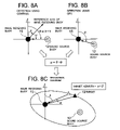
- FIGS. 8A to 8C are explanatory diagrams of an azimuth detection method in the second embodiment of the present invention.
- FIG. 9 is an explanatory diagram of a conventional azimuth detection method.
- FIG. 3 is a diagram showing a configuration of a bistatic azimuth detection system according to a first embodiment of the present invention.
- a wave receiving buoy 11 is wave receiving equipment thrown into the sea from an airplane 10 , and transmits received information (received wave signal) obtained by receiving a sound in the sea (a sound wave radiated from a sound source buoy 12 , its reflective sound, a reverberant sound, sea noise, etc.) with GPS position information on the wave receiving buoy 11 , which is obtained by using the Global Positioning System (GPS), to the airplane 10 by radio.
- GPS Global Positioning System
- the sound source buoy 12 is sound source equipment thrown into the sea from the airplane 10 , and transmits the GPS position information on the sound source buoy 12 by radio while transmitting a sound wave at a specific frequency into the sea by the control of the airplane 10 .
- a target 13 is in the sea and reflects a sound wave transmitted by the sound source buoy 12 .
- the airplane 10 mounts an arithmetic unit which calculates arrival azimuths of a sound transmitted from the sound source buoy 12 , and a reflective sound from the target 13 on the basis of the received signal from the wave receiving buoy 11 , and GPS position information on the wave receiving buoy 11 and sound source buoy 12 .
- FIG. 4 is a block diagram of the wave receiving buoy 11 and sound source buoy 12 in FIG. 3 .
- the wave receiving buoy 11 comprises an acoustic wave receiving unit 111 , a GPS receiver 112 , and a VHF transmitter 113 .
- the acoustic wave receiving unit 111 is a circuit which receives a sound wave in the sea, converts the received sound into an electric signal, performs signal processing of the electric signal such as amplification, and outputs the signal as a received wave signal, and the detailed configuration itself is well known up to now. Moreover, since it is not directly related to the present invention, the explanation of its detailed configuration will be omitted.
- the GPS receiver 112 receives GPS signals transmitted from a plurality of satellites (hereinafter GPS Satellites) which constitute the well-known GPS, and outputs the position information of latitude and longitude of a position where the wave receiving buoy 11 exists, and time information by a well-known method.
- the VHF transmitter 113 transmits to the airplane 10 the received wave signal from the acoustic wave receiving unit 111 and an output signal from the GPS receiver 112 as a signal in a VHF band.
- the sound source buoy 12 comprises a GPS receiver 121 and a VHF transmitter 122 , as shown in FIG. 4 .
- the GPS receiver 121 receives GPS signals transmitted from the GPS Satellites, and outputs the position information of latitude and longitude of a position where the sound source buoy 12 exist, and time information by a well-known method.
- the VHF transmitter 122 transmits to the airplane 10 the position information and time information from the GPS receiver 121 as a signal in a VHF band.
- the sound source buoy 12 has a receiving unit (not shown) which receives a radio control signal from the airplane 10 , and a sound wave generator (not shown) which is driven on the basis of the control signal and transmits a sound wave.
- a sound wave is transmitted in the sea from the sound source buoy 12 by the control of the airplane 10 in FIG. 3 , and the target 13 in the sea is made to reflect the sound wave.
- the acoustic wave receiving unit 111 receives a direct sound wave from the sound source buoy 12 , a reflective sound from the target 13 , a reverberant sound, sea noise, etc., converts the received sound into an electric signal, and outputs the signal as a received wave signal.
- the VHF transmitter 113 transmits the received signal to the airplane 10 together with the position information on the wave receiving buoy 11 and time information from the GPS receiver 112 .
- the arithmetic unit mounted in the airplane 10 receives the signal transmitted from the wave receiving buoy 11 , the position information on the sound source buoy 12 and time information, which is transmitted from the sound source buoy 12 , etc., and detects an azimuth of the target 13 by the following method on the basis of the received information.
- FIG. 5A shows a sound source arrival azimuth angle X° of a sound wave (direct wave), which is transmitted from the sound source buoy 12 and is directly received by the wave receiving buoy 11 , to a reference axis of the wave receiving buoy 11 .
- FIG. 5A shows a sound source arrival azimuth angle X° of a sound wave (direct wave), which is transmitted from the sound source buoy 12 and is directly received by the wave receiving buoy 11 , to a reference axis of the wave receiving buoy 11 .
- 5B shows a target arrival azimuth angle Y° of a reflective sound, which is received by the wave receiving buoy 11 after a sound wave transmitted from the sound source buoy 12 is reflected by the target 13 , to the reference axis of the wave receiving buoy 11 .
- the arithmetic unit draws a transition diagram as shown in FIG. 5C by the position information (latitude and longitude) detected by the GPS receiver 121 of the sound source buoy 12 , and the position information (latitude and longitude) detected by the GPS receiver 112 of the wave receiving buoy 11 . Further, it detects an azimuth angle ⁇ of a straight line, which ties the wave receiving buoy 11 and the sound source buoy 12 , to the magnetic north azimuth.
- the magnetic north azimuth is not that obtained with a compass, but is obtained from the transition diagram.
- the arithmetic unit detects the azimuth (target azimuth) of the target 13 to the magnetic north azimuth by the operation of ( ⁇ ) by using the differential azimuth angle ⁇ between the arrival azimuth of the direct wave and the arrival azimuth of the reflective sound and the azimuth angle ⁇ obtained by the position information on the wave receiving buoy 11 and sound source buoy 12 .
- the first embodiment obtains the position of the sound source buoy 12 , and the position of the wave receiving buoy 11 in high accuracy by using the GPS, and furthermore, detects the azimuth of the target from the difference between the arrival azimuth of the direct wave and the arrival azimuth of the reflective sound.
- FIG. 6 is a diagram showing a configuration of a bistatic azimuth detection system according to the second embodiment of the present invention.
- the same characters are assigned to the same components as those in FIG. 3 .
- a wave receiving buoy 15 is wave receiving equipment thrown into the sea from an airplane 16 , and transmits by radio the received information, obtained by receiving a sound in the sea, to the airplane 16 with GPS position information on the wave receiving buoy 11 .
- the sound source buoy 12 is sound source equipment thrown into the sea from the airplane 16 , and transmits the GPS position information on the sound source buoy 12 by radio while transmitting a sound wave into the sea by the control of the airplane 16 .
- a target 13 is in the sea and reflects a sound wave transmitted by the sound source buoy 12 .
- the airplane 16 mounts an arithmetic unit which calculates arrival azimuths of a sound transmitted from the sound source buoy 12 , and a reflective sound from the target 13 on the basis of the received signal from the wave receiving buoy 15 , and GPS position information on the wave receiving buoy 15 and sound source buoy 12 .
- FIG. 7 is a block diagram of the wave receiving buoy 15 and sound source buoy 12 in FIG. 6 .
- the wave receiving buoy 15 comprises an acoustic wave receiving unit 151 , a GPS receiver 152 , a compass 153 , and a VHF transmitter 154 .
- the acoustic wave receiving unit 151 is a circuit which receives a sound wave in the sea, converts the received sound into an electric signal, performs the amplification of the electric signal or the like, and outputs the signal as a received wave signal, and the detailed configuration itself is well known up to now. Moreover, since it is not directly related to the present invention, the explanation of its detailed configuration will be omitted.
- the GPS receiver 152 receives GPS signals transmitted from GPS Satellites, and outputs the position information of latitude and longitude of a position, where the wave receiving buoy 15 exists, and time information by a well-known method.
- the compass 153 outputs the magnetic north azimuth to the reference axis of the wave receiving buoy 15 .
- the VHF transmitter 154 transmits to the airplane 16 the received wave signal from the acoustic wave receiving unit 151 , an output signal from the GPS receiver 112 , and an output signal from the compass 153 as a signal in a VHF band.
- the configuration of the sound source buoy 12 is the same as that of the first embodiment.
- the arithmetic unit mounted in the airplane 16 receives the signal transmitted from the wave receiving buoy 15 , the position information on the sound source buoy 12 and time information, which is transmitted from the sound source buoy 12 , etc., and detects an azimuth of the target 13 by the following method on the basis of the received information.
- the arithmetic unit mounted in the airplane 16 first detects a sound source arrival azimuth Y° of the sound wave (direct wave), which is transmitted from the sound source buoy 12 and is directly received by the wave receiving buoy 15 , to the reference axis of the wave receiving buoy 15 , as shown in FIG. 8A by using a well known method.
- the arithmetic unit detects the magnetic north azimuth of the reference axis of the wave receiving buoy 15 .
- X° shows the magnetic north azimuth of the reference axis of the wave receiving buoy 15 .
- the arithmetic unit mounted in the airplane 16 detects an azimuth angle ⁇ of the sound source buoy 12 to the magnetic north azimuth of the wave receiving buoy 15 from the position information (latitude and longitude) detected by the GPS receiver 121 of the sound source buoy 12 , and the position information (latitude and longitude) detected by the GPS receiver 152 of the wave receiving buoy 15 .
- the magnetic north azimuth is not that obtained with the compass 153 , but is obtained from a transition diagram.
- the arithmetic unit detects an arrival azimuth angle ⁇ of the reflective sound from the target 13 to the magnetic north azimuth of the reference axis of the wave receiving buoy 15 by the conventional azimuth detection method, and further adds the azimuth correction value ⁇ to the arrival azimuth angle ⁇ to detect a highly accurate azimuth of the target 13 .
- the second embodiment calculates the difference between the azimuth angle ⁇ of the sound source buoy 12 , which is obtained by using the compass 153 , and the azimuth angle ⁇ of the sound source buoy 12 , which is obtained by using the GPS, to obtain the correction value ⁇ . Then, the second embodiment corrects the value ⁇ , calculated by the conventional detection method, with the correction value ⁇ to obtain the azimuth of the target 13 .
- the second embodiment corrects the value ⁇ , calculated by the conventional detection method, with the correction value ⁇ to obtain the azimuth of the target 13 .
- this invention is not limited to the above embodiments, and for example, it is possible to adopt another sound source equipment as the sound source buoy 12 , and it is possible to adopt another wave receiving equipment as the wave receiving buoy 12 .
- the arithmetic unit which performs azimuth detection is explained as what is mounted in an airplane, it is also possible to mount it in a vessel or the like.
Landscapes
- Engineering & Computer Science (AREA)
- Radar, Positioning & Navigation (AREA)
- Remote Sensing (AREA)
- Physics & Mathematics (AREA)
- Computer Networks & Wireless Communication (AREA)
- General Physics & Mathematics (AREA)
- Acoustics & Sound (AREA)
- Measurement Of Velocity Or Position Using Acoustic Or Ultrasonic Waves (AREA)
- Arrangements For Transmission Of Measured Signals (AREA)
Abstract
An arithmetic unit detects difference α (=X−Y) between a sound source arrival azimuth X° of a sound wave, which is transmitted from a sound source buoy and is directly received in a wave receiving buoy, to a reference axis of the wave receiving buoy, and a target arrival azimuth Y° of a reflective sound, which is reflected by a target, to the reference axis of the wave receiving buoy. The arithmetic unit detects an azimuth angle β of the sound source buoy on the basis of position information (latitude and longitude) of the sound source buoy and wave receiving buoy that is obtained by using GPS. Then, the arithmetic unit detects the azimuth (target azimuth) of the target to a magnetic north azimuth by the operation of (β−α).
Description
1. Field of the Invention
The present invention relates to a bistatic azimuth detection system and a detection method thereof, and in particular, relates to a bistatic azimuth detection system and a detection method which detect an azimuth of a target by receiving and analyzing a reflective sound, obtained by a sound which is radiated from sound source equipment and is reflected by the target in the sea, with one or more wave receiving equipment in positions different from that of the sound source equipment.
2. Description of the Related Art
In FIG. 9 , θ shows the above-described arrival azimuth. Moreover, the wave receiving unit 32 has a compass and detects a magnetic north azimuth of the reference axis of the wave receiving unit 32 to output it to the processing unit 33. In FIG. 9 , φ shows the magnetic north azimuth of the above-described reference axis. Then, the processing unit 33 adds the magnetic north azimuth φ of the reference axis to the arrival azimuth θ of the reflective sound from the target 31, and detects the result as a target azimuth of the target 31.
In addition, bistatic azimuth detection equipment which automates target echo detection and target position localization is also known conventionally (for example, refer to Japanese Patent Laid-Open No. 2001-296359). The conventional bistatic azimuth detection equipment mentioned in Japanese Patent Laid-Open No. 2001-296359 comprises a signal processing unit which performs the processing of removing a narrow-band signal whose frequency is stable in time, from an acoustic signal received by a receiving unit, and emphasizing a target echo, a primary detection processing unit which extracts a signal appropriate for a target echo by setting a threshold, a secondary detection processing unit which classifies the result of primary detection processing into categories, such as a target echo, a direct wave, a submarine reflective wave, and sea noise, by a neural network, and detects the target echo, and a target position localization processing unit which calculates arrival time difference between the detected target echo and direct wave, and localizes a target existence zone by ellipse drawing to detect a target position from an intersection with a signal arrival azimuth.
Further, a signal detection system is known conventionally, the signal detection system which can distinguish whether a received echo is one from a true target or one reflected on a sea surface or a sea bottom. The signal detection system includes a plurality of directive passive sonobuoys each receiving an echo of a sound wave which a sound source sonobuoy radiates underwater, calculates an existence zone of the target, which is a sound source of echoes which they receive (including a sea surface and a sea bottom), on a two-dimensional coordinate plane for every directive passive sonobuoy from the positional relation and propagation time between the sound source sonobuoy and each of directive passive sonobuoys, cumulates an echo level for every target existence zone, and compares the echo cumulation level with a threshold level (for example, refer to Japanese Patent Laid-Open No. 7-294640).
However, the conventional bistatic azimuth detection method shown in FIG. 9 cannot perform highly accurate azimuth detection due to error factors such as the accuracy of a compass, and an earth magnetism deviation. In addition, since an azimuth detection function such as a compass is indispensable, a mechanism is enlarged and cost increases.
In addition, since the conventional equipment mentioned in Japanese Patent Laid-Open No. 2001-296359 performs classification into categories, such as a target echo, a direct wave, a submarine reflective sound, and sea noise, by a neural network, and detects the target echo, a load of a computer is large. The configuration of equipment is also complicated and expensive. Moreover, since it determines a magnetic north azimuth with a compass and estimates an existence position of a target by using an arrival azimuth of the target, it is also not possible to perform highly accurate azimuth detection due to the above-described error factors such as the accuracy of a compass, and an earth magnetism deviation.
Furthermore, since the conventional system mentioned in Japanese Patent Laid-Open No. 7-294640 calculates an existence azimuth of a target by using directional characteristics of three directive passive sonobuoys, three passive sonobuoys are required. Since each passive sonobuoy has a compass and detects a magnetic north direction, it is not possible to perform highly accurate azimuth detection due to the above-described error factors such as the accuracy of a compass, and an earth magnetism deviation.
The present invention aims at providing a bistatic azimuth detection system and a detection method thereof which can perform more highly accurate azimuth detection than the conventional regardless of errors due to the detection by a compass.
In order to achieve the above-described objects, in a bistatic system which detects a target azimuth by typically radiating a sound wave into the sea from sound source equipment, receiving a reflective sound, reflected by the target in the sea, by one or more wave receiving equipment separated from the sound source equipment, and analyzing the received wave signal, the target azimuth is detected on the basis of an azimuth of the sound source equipment which is calculated from position information on the sound source equipment and wave receiving equipment, and an azimuth of the sound source equipment which is obtained by analyzing the received wave signal.
According to the first aspect of the present invention, as shown in FIGS. 1 and 2 , a bistatic azimuth detection system comprising: sound source equipment 2 which transmits a sound wave to a target 3 in the sea and transmits first position information on the equipment 2; wave receiving equipment 1 which transmits second position information on the wave receiving equipment 1 with a received wave signal which is obtained by receiving a direct wave from the sound source equipment 2 and a reflective sound from the target 3; sound source azimuth detection means 4 which detects an azimuth of the sound source equipment 2 viewed from the wave receiving equipment 1 on the basis of the first and second position information; arrival azimuth detection means 5 which detects a sound source arrival azimuth 6, which is an arrival azimuth of the direct wave from the sound source equipment 2, and a target arrival azimuth 7, which is an arrival azimuth of the reflective sound from the target 3, on the basis of the received wave signal; a subtractor circuit 8 which calculates difference between them; and target azimuth detection means 9 which detects an azimuth of the target 3 on the basis of the azimuth detected by the sound source azimuth detection means 4, and the difference calculated by the subtractor circuit 8. Here, the arrival azimuth detection means 5 and the subtractor circuit 8 constitute calculation means.
It is possible to obtain a highly accurate target azimuth without a compass by calculating the difference between the sound source arrival azimuth 6 and target arrival azimuth 7 which are obtained from the received wave signal, and detecting the azimuth of the target 3 on the basis of the azimuth detected by the sound source azimuth detection means 4, and the difference calculated by the calculation means.
According to the second aspect of the present invention, a bistatic azimuth detection system comprising: sound source equipment which transmits a sound wave to a target in the sea and transmits first position information on the equipment; wave receiving equipment which transmits second position information on the wave receiving equipment with a received wave signal which is obtained by receiving a direct wave from the sound source equipment and a reflective sound from the target, and specific azimuth information on a specific azimuth obtained by a compass; first sound source azimuth detection means which detects an azimuth of the sound source equipment to a specific azimuth in the wave receiving equipment on the basis of the first and second position information; second sound source azimuth detection means which detects an arrival azimuth of the direct wave to the specific azimuth in the specific azimuth information on the basis of the received wave signal and the specific azimuth information; target azimuth detection means which detects a target azimuth, which is an arrival azimuth of the reflective sound, to the specific azimuth in the specific azimuth information on the basis of the received wave signal and the specific azimuth information; and azimuth correction means which corrects the target azimuth with the difference between the azimuth detected by the first detection means and the azimuth detected by the second detection means.
According to the second aspect of the present invention, the azimuth of the sound source equipment to a specific azimuth (for example, a magnetic north azimuth) is detected on the basis of the first and second position information, the arrival azimuth of the direct wave to a specific azimuth which a compass shows (for example, a magnetic north azimuth) is detected on the basis of the received wave signal, and the target azimuth to the specific azimuth is detected on the basis of the received wave signal and the specific azimuth information. Then, the target azimuth is corrected with the difference between the azimuth of the sound source equipment and the arrival azimuth of the direct wave. Hence, it is possible to perform highly accurate detection with no influence of the accuracy of a compass, an earth magnetism deviation, etc. which lead to azimuth errors.
The sound source equipment wirelessly transmits the first position information, and the wave receiving equipment wirelessly transmits the received wave signal and the second position information.
Each of the sound source equipment and the wave receiving equipment receives signals from satellites of the Global Positioning System to acquire longitude and latitude information on the equipment as the position information on the equipment.
According to the third aspect of the present invention, a bistatic azimuth detection method of a bistatic azimuth detection system which includes sound source equipment, which transmits a sound wave to a target in the sea and transmits first position information on the equipment, and wave receiving equipment, which transmits second position information on the wave receiving equipment with a received wave signal which is obtained by receiving a direct wave from the sound source equipment and a reflective sound from the target, comprising: a first step of detecting an azimuth of the sound source equipment viewed from the wave receiving equipment on the basis of the first and second position information; a second step of detecting a sound source arrival azimuth, which is an arrival azimuth of the direct wave from the sound source equipment, and a target arrival azimuth, which is an arrival azimuth of the reflective sound from the target, on the basis of the received wave signal to calculate difference between them; and a third step of detecting an azimuth of the target on the basis of the azimuth detected at the first step, and the difference calculated at the second step.
Similarly to the first aspect of the present invention, It is possible to obtain a highly accurate target azimuth without a compass by calculating the difference between the sound source arrival azimuth 6 and target arrival azimuth 7 which are obtained from the received wave signal, and detecting the azimuth of the target 3 on the basis of the azimuth detected by the sound source azimuth detection means 4, and the difference calculated by the calculation means.
According to the fourth aspect of the present invention, a bistatic azimuth detection method of a bistatic azimuth detection system which includes sound source equipment which transmits a sound wave to the target in the sea and transmits first position information on the equipment, and wave receiving equipment which transmits second position information on the wave receiving equipment with a received wave signal which is obtained by receiving a direct wave from the sound source equipment and a reflective sound from the target, and specific azimuth information on a specific azimuth obtained by a compass, comprising: a first step of detecting an azimuth of the sound source equipment to a specific azimuth in the wave receiving equipment on the basis of the first and second position information; a second step of detecting an arrival azimuth of the direct wave to the specific azimuth in the specific azimuth information on the basis of the received wave signal and the specific azimuth information; a third step of detecting a target azimuth, which is an arrival azimuth of the reflective sound, to the specific azimuth in the specific azimuth information on the basis of the received wave signal and the specific azimuth information; and a fourth step of correcting the target azimuth with difference between the azimuth detected at the first step and the azimuth detected at the second step.
Similarly to the second aspect of the present invention, the azimuth of the sound source equipment to a specific azimuth (for example, a magnetic north azimuth) is detected on the basis of the first and second position information, the arrival azimuth of the direct wave to a specific azimuth which a compass shows (for example, a magnetic north azimuth) is detected on the basis of the received wave signal, and the target azimuth to the specific azimuth is detected on the basis of the received wave signal and the specific azimuth information. Then, the target azimuth is corrected with the difference between the azimuth of the sound source equipment and the arrival azimuth of the direct wave. Hence, it is possible to perform highly accurate detection with no influence of the accuracy of a compass, an earth magnetism deviation, etc. which lead to azimuth errors.
Embodiments of the present invention will be explained with drawings. FIG. 3 is a diagram showing a configuration of a bistatic azimuth detection system according to a first embodiment of the present invention. In FIG. 3 , a wave receiving buoy 11 is wave receiving equipment thrown into the sea from an airplane 10, and transmits received information (received wave signal) obtained by receiving a sound in the sea (a sound wave radiated from a sound source buoy 12, its reflective sound, a reverberant sound, sea noise, etc.) with GPS position information on the wave receiving buoy 11, which is obtained by using the Global Positioning System (GPS), to the airplane 10 by radio.
The sound source buoy 12 is sound source equipment thrown into the sea from the airplane 10, and transmits the GPS position information on the sound source buoy 12 by radio while transmitting a sound wave at a specific frequency into the sea by the control of the airplane 10. A target 13 is in the sea and reflects a sound wave transmitted by the sound source buoy 12. The airplane 10 mounts an arithmetic unit which calculates arrival azimuths of a sound transmitted from the sound source buoy 12, and a reflective sound from the target 13 on the basis of the received signal from the wave receiving buoy 11, and GPS position information on the wave receiving buoy 11 and sound source buoy 12.
The GPS receiver 112 receives GPS signals transmitted from a plurality of satellites (hereinafter GPS Satellites) which constitute the well-known GPS, and outputs the position information of latitude and longitude of a position where the wave receiving buoy 11 exists, and time information by a well-known method. The VHF transmitter 113 transmits to the airplane 10 the received wave signal from the acoustic wave receiving unit 111 and an output signal from the GPS receiver 112 as a signal in a VHF band.
The sound source buoy 12 comprises a GPS receiver 121 and a VHF transmitter 122, as shown in FIG. 4 . The GPS receiver 121 receives GPS signals transmitted from the GPS Satellites, and outputs the position information of latitude and longitude of a position where the sound source buoy 12 exist, and time information by a well-known method. The VHF transmitter 122 transmits to the airplane 10 the position information and time information from the GPS receiver 121 as a signal in a VHF band. In addition, the sound source buoy 12 has a receiving unit (not shown) which receives a radio control signal from the airplane 10, and a sound wave generator (not shown) which is driven on the basis of the control signal and transmits a sound wave.
In the first embodiment, a sound wave is transmitted in the sea from the sound source buoy 12 by the control of the airplane 10 in FIG. 3 , and the target 13 in the sea is made to reflect the sound wave. The acoustic wave receiving unit 111 receives a direct sound wave from the sound source buoy 12, a reflective sound from the target 13, a reverberant sound, sea noise, etc., converts the received sound into an electric signal, and outputs the signal as a received wave signal. The VHF transmitter 113 transmits the received signal to the airplane 10 together with the position information on the wave receiving buoy 11 and time information from the GPS receiver 112.
The arithmetic unit mounted in the airplane 10 receives the signal transmitted from the wave receiving buoy 11, the position information on the sound source buoy 12 and time information, which is transmitted from the sound source buoy 12, etc., and detects an azimuth of the target 13 by the following method on the basis of the received information.
Next, an azimuth detection method according to the first embodiment will be explained in detail with reference to FIGS. 5A to 5C . The arithmetic unit mounted in the airplane 10 first detects arrival azimuths of a direct wave and a reflective sound by a well-known method on the basis of the received information. FIG. 5A shows a sound source arrival azimuth angle X° of a sound wave (direct wave), which is transmitted from the sound source buoy 12 and is directly received by the wave receiving buoy 11, to a reference axis of the wave receiving buoy 11. FIG. 5B shows a target arrival azimuth angle Y° of a reflective sound, which is received by the wave receiving buoy 11 after a sound wave transmitted from the sound source buoy 12 is reflected by the target 13, to the reference axis of the wave receiving buoy 11.
Then, the arithmetic unit mounted in the airplane 10 detects difference α (=X−Y) between the above-described sound source arrival azimuth X° and target arrival azimuth Y°. Next, the arithmetic unit draws a transition diagram as shown in FIG. 5C by the position information (latitude and longitude) detected by the GPS receiver 121 of the sound source buoy 12, and the position information (latitude and longitude) detected by the GPS receiver 112 of the wave receiving buoy 11. Further, it detects an azimuth angle β of a straight line, which ties the wave receiving buoy 11 and the sound source buoy 12, to the magnetic north azimuth. In addition, the magnetic north azimuth is not that obtained with a compass, but is obtained from the transition diagram.
Then, as shown in FIG. 5C , the arithmetic unit detects the azimuth (target azimuth) of the target 13 to the magnetic north azimuth by the operation of (β−α) by using the differential azimuth angle α between the arrival azimuth of the direct wave and the arrival azimuth of the reflective sound and the azimuth angle β obtained by the position information on the wave receiving buoy 11 and sound source buoy 12. Thus, the first embodiment obtains the position of the sound source buoy 12, and the position of the wave receiving buoy 11 in high accuracy by using the GPS, and furthermore, detects the azimuth of the target from the difference between the arrival azimuth of the direct wave and the arrival azimuth of the reflective sound. Hence, it is possible to perform highly accurate azimuth detection with no influence of the accuracy of a compass, an earth magnetism deviation, etc. which lead to conventional azimuth errors.
Next, a second embodiment of the present invention will be explained. FIG. 6 is a diagram showing a configuration of a bistatic azimuth detection system according to the second embodiment of the present invention. In FIG. 6 , the same characters are assigned to the same components as those in FIG. 3 . In FIG. 6 , a wave receiving buoy 15 is wave receiving equipment thrown into the sea from an airplane 16, and transmits by radio the received information, obtained by receiving a sound in the sea, to the airplane 16 with GPS position information on the wave receiving buoy 11.
The sound source buoy 12 is sound source equipment thrown into the sea from the airplane 16, and transmits the GPS position information on the sound source buoy 12 by radio while transmitting a sound wave into the sea by the control of the airplane 16. A target 13 is in the sea and reflects a sound wave transmitted by the sound source buoy 12. The airplane 16 mounts an arithmetic unit which calculates arrival azimuths of a sound transmitted from the sound source buoy 12, and a reflective sound from the target 13 on the basis of the received signal from the wave receiving buoy 15, and GPS position information on the wave receiving buoy 15 and sound source buoy 12.
The GPS receiver 152 receives GPS signals transmitted from GPS Satellites, and outputs the position information of latitude and longitude of a position, where the wave receiving buoy 15 exists, and time information by a well-known method. The compass 153 outputs the magnetic north azimuth to the reference axis of the wave receiving buoy 15. The VHF transmitter 154 transmits to the airplane 16 the received wave signal from the acoustic wave receiving unit 151, an output signal from the GPS receiver 112, and an output signal from the compass 153 as a signal in a VHF band. In addition, the configuration of the sound source buoy 12 is the same as that of the first embodiment.
The arithmetic unit mounted in the airplane 16 receives the signal transmitted from the wave receiving buoy 15, the position information on the sound source buoy 12 and time information, which is transmitted from the sound source buoy 12, etc., and detects an azimuth of the target 13 by the following method on the basis of the received information.
Next, an azimuth detection method according to the second embodiment will be explained in detail with reference to FIGS. 8A to 8C . On the basis of the received information, the arithmetic unit mounted in the airplane 16 first detects a sound source arrival azimuth Y° of the sound wave (direct wave), which is transmitted from the sound source buoy 12 and is directly received by the wave receiving buoy 15, to the reference axis of the wave receiving buoy 15, as shown in FIG. 8A by using a well known method. In addition, on the basis of the information from the compass 153 of the wave receiving buoy 15, the arithmetic unit detects the magnetic north azimuth of the reference axis of the wave receiving buoy 15. In FIG. 8A , X° shows the magnetic north azimuth of the reference axis of the wave receiving buoy 15.
Next, the arithmetic unit mounted in the airplane 16 calculates a sum (X+Y) of the above-described arrival azimuth Y° and the magnetic north azimuth X°, and detects it as an azimuth angle φ (=X+Y) of the sound source buoy 12.
Then, as shown in FIG. 8B , the arithmetic unit mounted in the airplane 16 detects an azimuth angle θ of the sound source buoy 12 to the magnetic north azimuth of the wave receiving buoy 15 from the position information (latitude and longitude) detected by the GPS receiver 121 of the sound source buoy 12, and the position information (latitude and longitude) detected by the GPS receiver 152 of the wave receiving buoy 15. In addition, the magnetic north azimuth is not that obtained with the compass 153, but is obtained from a transition diagram.
Then, the arithmetic unit calculates difference between the azimuth angle φ of the sound source buoy 12, which is obtained by using the compass 153, and the azimuth angle θ of the sound source buoy 12, which is obtained by using the GPS, and detects it as an azimuth correction value α. If there were no error in the compass 153 and azimuth detection, it would be φ=θ, but actually, the error α arises due to magnetic variation, the accuracy of a compass, etc.
Next, as shown in FIG. 8C , the arithmetic unit detects an arrival azimuth angle β of the reflective sound from the target 13 to the magnetic north azimuth of the reference axis of the wave receiving buoy 15 by the conventional azimuth detection method, and further adds the azimuth correction value α to the arrival azimuth angle β to detect a highly accurate azimuth of the target 13.
Thus, before detecting the azimuth of the target 13, the second embodiment calculates the difference between the azimuth angle φ of the sound source buoy 12, which is obtained by using the compass 153, and the azimuth angle θ of the sound source buoy 12, which is obtained by using the GPS, to obtain the correction value α. Then, the second embodiment corrects the value β, calculated by the conventional detection method, with the correction value α to obtain the azimuth of the target 13. Hence, it becomes possible to perform highly accurate detection with no influence of the accuracy of a compass, the earth magnetism deviation, etc. which lead to conventional azimuth errors.
In addition, this invention is not limited to the above embodiments, and for example, it is possible to adopt another sound source equipment as the sound source buoy 12, and it is possible to adopt another wave receiving equipment as the wave receiving buoy 12. Furthermore, although the arithmetic unit which performs azimuth detection is explained as what is mounted in an airplane, it is also possible to mount it in a vessel or the like. Moreover, it is also possible to provide two or more wave receiving buoys and one or more sound source buoys.
Claims (16)
1. A bistatic azimuth detection system comprising:
sound source equipment which transmits a sound wave to a target and transmits first position information on the sound source equipment;
wave receiving equipment which transmits second position information on the wave receiving equipment with a received wave signal which is obtained by receiving a direct wave from the sound source equipment and a reflective sound from the target;
sound source azimuth detection means which detects an azimuth of the sound source equipment viewed from the wave receiving equipment on the basis of the first and second position information;
calculation means which detects a sound source arrival azimuth, which is an arrival azimuth of the direct wave from the sound source equipment, and a target arrival azimuth, which is an arrival azimuth of the reflective sound from the target, on the basis of the received wave signal, to calculate difference between them; and
target azimuth detection means which detects an azimuth of the target on the basis of the azimuth detected by the sound source azimuth detection means, and the difference calculated by the calculation means.
2. A bistatic azimuth detection system comprising:
sound source equipment which transmits a sound wave to a target and transmits first position information on the equipment;
wave receiving equipment which transmits second position information on the wave receiving equipment with a received wave signal which is obtained by receiving a direct wave from the sound source equipment and a reflective sound from the target, and specific azimuth information on a specific azimuth obtained by a compass;
first sound source azimuth detection means which detects an azimuth of the sound source equipment to a specific azimuth in the wave receiving equipment on the basis of the first and second position information;
second sound source azimuth detection means which detects an arrival azimuth of the direct wave to the specific azimuth in the specific azimuth information on the basis of the received wave signal and the specific azimuth information;
target azimuth detection means which detects a target azimuth, which is an arrival azimuth of the reflective sound, to the specific azimuth in the specific azimuth information on the basis of the received wave signal and the specific azimuth information; and
azimuth correction means which corrects the target azimuth with the difference between the azimuth detected by the first detection means and the azimuth detected by the second detection means.
3. The bistatic azimuth detection system according to claim 1 , wherein the sound source equipment wirelessly transmits the first position information, and wherein the wave receiving equipment wirelessly transmits the received wave signal and the second position information.
4. The bistatic azimuth detection system according to claim 1 , wherein each of the sound source equipment and the wave receiving equipment receives signals from satellites of the Global Positioning System to acquire longitude and latitude information on the equipment as the position information on the equipment.
5. A bistatic azimuth detection method of a bistatic azimuth detection system which includes sound source equipment, which transmits a sound wave to a target and transmits first position information on the equipment, and wave receiving equipment, which transmits second position information on the wave receiving equipment with a received wave signal which is obtained by receiving a direct wave from the sound source equipment and a reflective sound from the target, comprising:
a first step of detecting an azimuth of the sound source equipment viewed from the wave receiving equipment on the basis of the first and second position information;
a second step of detecting a sound source arrival azimuth, which is an arrival azimuth of the direct wave from the sound source equipment, and a target arrival azimuth, which is an arrival azimuth of the reflective sound from the target, on the basis of the received wave signal to calculate difference between them; and
a third step of detecting an azimuth of the target on the basis of the azimuth detected at the first step, and the difference calculated at the second step.
6. A bistatic azimuth detection method of a bistatic azimuth detection system which includes sound source equipment which transmits a sound wave to the target and transmits first position information on the equipment, and wave receiving equipment which transmits second position information on the wave receiving equipment with a received wave signal which is obtained by receiving a direct wave from the sound source equipment and a reflective sound from the target, and specific azimuth information on a specific azimuth obtained by a compass, comprising:
a first step of detecting an azimuth of the sound source equipment to a specific azimuth in the wave receiving equipment on the basis of the first and second position information;
a second step of detecting an arrival azimuth of the direct wave to the specific azimuth in the specific azimuth information on the basis of the received wave signal and the specific azimuth information;
a third step of detecting a target azimuth, which is an arrival azimuth of the reflective sound, to the specific azimuth in the specific azimuth information on the basis of the received wave signal and the specific azimuth information; and
a fourth step of correcting the target azimuth with difference between the azimuth detected at the first step and the azimuth detected at the second step.
7. The detection method according to claim 5 , wherein the sound source equipment wirelessly transmits the first position information, and wherein the wave receiving equipment wirelessly transmits the received wave signal and the second position information.
8. The detection method according to claim 5 , wherein each of the sound source equipment and the wave receiving equipment receives signals from satellites of the Global Positioning System to acquire longitude and latitude information on the equipment as the position information on the equipment.
9. A bistatic azimuth detection system comprising:
sound source equipment which transmits a sound wave to a target in the sea and transmits first position information on the sound source equipment;
wave receiving equipment which transmits second position information on the wave receiving equipment with a received wave signal which is obtained by receiving a direct wave from the sound source equipment and a reflective sound from the target;
a sound source azimuth detector which detects an azimuth of the sound source equipment viewed from the wave receiving equipment on the basis of the first and second position information;
a calculator which detects a sound source arrival azimuth, which is an arrival azimuth of the direct wave from the sound source equipment, and a target arrival azimuth, which is an arrival azimuth of the reflective sound from the target, on the basis of the received wave signal, to calculate difference between them; and
a target azimuth detector which detects an azimuth of the target on the basis of the azimuth detected by the sound source azimuth detector, and the difference calculated by the calculator.
10. A bistatic azimuth detection system comprising:
sound source equipment which transmits a sound wave to a target in the sea and transmits first position information on the equipment;
wave receiving equipment which transmits second position information on the wave receiving equipment with a received wave signal which is obtained by receiving a direct wave from the sound source equipment and a reflective sound from the target, and specific azimuth information on a specific azimuth obtained by a compass;
a first sound source azimuth detector which detects an azimuth of the sound source equipment to a specific azimuth in the wave receiving equipment on the basis of the first and second position information;
a second sound source azimuth detector which detects an arrival azimuth of the direct wave to the specific azimuth in the specific azimuth information on the basis of the received wave signal and the specific azimuth information;
a target azimuth detector which detects a target azimuth, which is an arrival azimuth of the reflective sound, to the specific azimuth in the specific azimuth information on the basis of the received wave signal and the specific azimuth information; and
an azimuth correction device which corrects the target azimuth with the difference between the azimuth detected by the first sound source azimuth detector and the azimuth detected by the second source azimuth detector.
11. The bistatic azimuth detection system according to claim 9 , wherein the sound source equipment wirelessly transmits the first position information, and wherein the wave receiving equipment wirelessly transmits the received wave signal and the second position information.
12. The bistatic azimuth detection system according to claim 9 , wherein each of the sound source equipment and the wave receiving equipment receives signals from satellites of the Global Positioning System to acquire longitude and latitude information on the equipment as the position information on the equipment.
13. The bistatic azimuth detection system according to claim 1 , wherein the target is in the sea.
14. The bistatic azimuth detection system according to claim 2 , wherein the target is in the sea.
15. The detection method according to claim 5 , wherein the target is in the sea.
16. The detection method according to claim 6 , wherein the target is in the sea.
Applications Claiming Priority (2)
| Application Number | Priority Date | Filing Date | Title |
|---|---|---|---|
| JP052425/2003 | 2003-02-28 | ||
| JP2003052425A JP4266669B2 (en) | 2003-02-28 | 2003-02-28 | Bistatic orientation detection system and detection method |
Publications (2)
| Publication Number | Publication Date |
|---|---|
| US20040170085A1 US20040170085A1 (en) | 2004-09-02 |
| US7088641B2 true US7088641B2 (en) | 2006-08-08 |
Family
ID=32040892
Family Applications (1)
| Application Number | Title | Priority Date | Filing Date |
|---|---|---|---|
| US10/784,941 Active 2024-06-07 US7088641B2 (en) | 2003-02-28 | 2004-02-25 | Bistatic azimuth detection system and detection method |
Country Status (4)
| Country | Link |
|---|---|
| US (1) | US7088641B2 (en) |
| JP (1) | JP4266669B2 (en) |
| CA (1) | CA2458509C (en) |
| GB (1) | GB2398872B8 (en) |
Families Citing this family (9)
| Publication number | Priority date | Publication date | Assignee | Title |
|---|---|---|---|---|
| JP4266669B2 (en) * | 2003-02-28 | 2009-05-20 | 日本電気株式会社 | Bistatic orientation detection system and detection method |
| JP2006164212A (en) * | 2004-11-10 | 2006-06-22 | Sony Corp | Information processing apparatus and method, recording medium, and program |
| RU2469346C1 (en) * | 2011-07-11 | 2012-12-10 | Федеральное государственное бюджетное учреждение науки Тихоокеанский океанологический институт им. В.И. Ильичева Дальневосточного отделения Российской академии наук (ТОИ ДВО РАН) | Method of positioning underwater objects |
| DE102014000561A1 (en) * | 2014-01-15 | 2015-07-16 | Thyssenkrupp Marine Systems Gmbh | Detecting objects at sea using a mobile sonar emitter |
| CN105487048B (en) * | 2015-11-02 | 2018-02-02 | 中国人民解放军国防科学技术大学 | The two station bearing-only location confusion region methods based on fiducial confidence ellipse |
| CN110346802B (en) * | 2018-04-08 | 2023-07-21 | 哈尔滨工业大学(威海) | Underwater target detection method based on calculation of underwater acoustic channel parameters |
| CN109870695B (en) * | 2019-02-21 | 2023-02-03 | 哈尔滨工程大学 | Deep sea bottom reflected sound-based non-cooperative target multi-node underwater sound positioning method |
| KR102406316B1 (en) * | 2020-06-05 | 2022-06-08 | 국방과학연구소 | Detecting method and system of an underwater target |
| CN114237305A (en) * | 2021-11-27 | 2022-03-25 | 河北汉光重工有限责任公司 | Direction control calculation method of sound wave rejection system |
Citations (7)
| Publication number | Priority date | Publication date | Assignee | Title |
|---|---|---|---|---|
| US4746924A (en) * | 1985-09-30 | 1988-05-24 | The Boeing Company | Apparatus and methods for locating a target utilizing signals generated from a non-cooperative source |
| JPH0815427A (en) | 1994-06-28 | 1996-01-19 | Oki Electric Ind Co Ltd | Sound measuring buoy |
| USH1618H (en) | 1995-05-30 | 1996-12-03 | United States Of America | Coherent arrays of drifting sonobuoys |
| WO1997022889A1 (en) * | 1995-12-19 | 1997-06-26 | Commonwealth Of Australia | A tracking method for a radar system |
| GB2320556A (en) | 1993-02-23 | 1998-06-24 | Marconi Gec Ltd | Gun launchable sensor |
| JP2001296359A (en) | 2000-04-14 | 2001-10-26 | Nec Corp | Bistatic processing apparatus |
| GB2398872A (en) * | 2003-02-28 | 2004-09-01 | Nec Corp | Bistatic azimuth detection using position information on sound source and wave receiving equipment |
-
2003
- 2003-02-28 JP JP2003052425A patent/JP4266669B2/en not_active Expired - Fee Related
-
2004
- 2004-02-23 GB GB0403949A patent/GB2398872B8/en not_active Expired - Fee Related
- 2004-02-24 CA CA002458509A patent/CA2458509C/en not_active Expired - Fee Related
- 2004-02-25 US US10/784,941 patent/US7088641B2/en active Active
Patent Citations (7)
| Publication number | Priority date | Publication date | Assignee | Title |
|---|---|---|---|---|
| US4746924A (en) * | 1985-09-30 | 1988-05-24 | The Boeing Company | Apparatus and methods for locating a target utilizing signals generated from a non-cooperative source |
| GB2320556A (en) | 1993-02-23 | 1998-06-24 | Marconi Gec Ltd | Gun launchable sensor |
| JPH0815427A (en) | 1994-06-28 | 1996-01-19 | Oki Electric Ind Co Ltd | Sound measuring buoy |
| USH1618H (en) | 1995-05-30 | 1996-12-03 | United States Of America | Coherent arrays of drifting sonobuoys |
| WO1997022889A1 (en) * | 1995-12-19 | 1997-06-26 | Commonwealth Of Australia | A tracking method for a radar system |
| JP2001296359A (en) | 2000-04-14 | 2001-10-26 | Nec Corp | Bistatic processing apparatus |
| GB2398872A (en) * | 2003-02-28 | 2004-09-01 | Nec Corp | Bistatic azimuth detection using position information on sound source and wave receiving equipment |
Also Published As
| Publication number | Publication date |
|---|---|
| GB2398872B8 (en) | 2005-09-26 |
| GB0403949D0 (en) | 2004-03-24 |
| GB2398872A8 (en) | 2005-09-26 |
| US20040170085A1 (en) | 2004-09-02 |
| JP4266669B2 (en) | 2009-05-20 |
| CA2458509C (en) | 2008-12-02 |
| GB2398872A (en) | 2004-09-01 |
| JP2004264070A (en) | 2004-09-24 |
| GB2398872B (en) | 2005-06-01 |
| CA2458509A1 (en) | 2004-08-28 |
Similar Documents
| Publication | Publication Date | Title |
|---|---|---|
| US5615175A (en) | Passive direction finding device | |
| JP6691096B2 (en) | Deception signal detection system and deception signal detection method | |
| RU2365939C1 (en) | Method of underwater navigation | |
| US7639565B2 (en) | Point source localization sonar system and method | |
| RU2371738C1 (en) | Hydroacoustic navigation system | |
| RU2456634C1 (en) | Method of navigating submarine object using hydroacoustic navigation system | |
| KR102333335B1 (en) | Underwater device positioning device and method | |
| CN110703203A (en) | Underwater pulsed sound positioning system based on multi-acoustic wave glider | |
| CN110727282B (en) | AUV docking method and device and underwater docking system | |
| US7088641B2 (en) | Bistatic azimuth detection system and detection method | |
| US6600444B2 (en) | System and method for computing navigation information in the presence of interference | |
| US11953580B2 (en) | Over the horizon radar (OTH) system and method | |
| USH1618H (en) | Coherent arrays of drifting sonobuoys | |
| CN116358544A (en) | Method and system for correcting inertial navigation error based on acoustic feature matching positioning | |
| JP2865082B2 (en) | Radio wave receiver | |
| Fabrizio | Geolocation of HF skywave radar signals using multipath in an unknown ionosphere | |
| JP2861803B2 (en) | Signal detection method | |
| US20080186232A1 (en) | Method of and apparatus for true north azimuth determination using the combination of crossed loop antenna and radio positioning system technologies | |
| JPS6336174A (en) | Buoy for underwater position measurement | |
| RU2389042C2 (en) | Method of determining protective limit around position of moving body calculated from satellite signals | |
| JPH08114664A (en) | Radio sonobuoy position detecting system | |
| JP4657050B2 (en) | Speed vector determination system | |
| JPH01153988A (en) | Position detecting device | |
| EP1862756B1 (en) | Apparatus and method for estimating altitude | |
| KR20130115834A (en) | Ship location system and method |
Legal Events
| Date | Code | Title | Description |
|---|---|---|---|
| AS | Assignment |
Owner name: NEC CORPORATION, JAPAN Free format text: ASSIGNMENT OF ASSIGNORS INTEREST;ASSIGNORS:TSUBOTA, KOUTAROU;MORIOKA, HIROYUKI;KANESADA, HIROYUKI;AND OTHERS;REEL/FRAME:015023/0955 Effective date: 20040213 |
|
| STCF | Information on status: patent grant |
Free format text: PATENTED CASE |
|
| FPAY | Fee payment |
Year of fee payment: 4 |
|
| FPAY | Fee payment |
Year of fee payment: 8 |
|
| MAFP | Maintenance fee payment |
Free format text: PAYMENT OF MAINTENANCE FEE, 12TH YEAR, LARGE ENTITY (ORIGINAL EVENT CODE: M1553) Year of fee payment: 12 |