US6751030B2 - Zoom lens and image-taking apparatus - Google Patents
Zoom lens and image-taking apparatus Download PDFInfo
- Publication number
- US6751030B2 US6751030B2 US10/452,029 US45202903A US6751030B2 US 6751030 B2 US6751030 B2 US 6751030B2 US 45202903 A US45202903 A US 45202903A US 6751030 B2 US6751030 B2 US 6751030B2
- Authority
- US
- United States
- Prior art keywords
- lens unit
- lens
- zoom lens
- wide angle
- focal length
- Prior art date
- Legal status (The legal status is an assumption and is not a legal conclusion. Google has not performed a legal analysis and makes no representation as to the accuracy of the status listed.)
- Expired - Lifetime
Links
Images
Classifications
-
- G—PHYSICS
- G02—OPTICS
- G02B—OPTICAL ELEMENTS, SYSTEMS OR APPARATUS
- G02B15/00—Optical objectives with means for varying the magnification
- G02B15/14—Optical objectives with means for varying the magnification by axial movement of one or more lenses or groups of lenses relative to the image plane for continuously varying the equivalent focal length of the objective
- G02B15/144—Optical objectives with means for varying the magnification by axial movement of one or more lenses or groups of lenses relative to the image plane for continuously varying the equivalent focal length of the objective having four groups only
- G02B15/1441—Optical objectives with means for varying the magnification by axial movement of one or more lenses or groups of lenses relative to the image plane for continuously varying the equivalent focal length of the objective having four groups only the first group being positive
- G02B15/144113—Optical objectives with means for varying the magnification by axial movement of one or more lenses or groups of lenses relative to the image plane for continuously varying the equivalent focal length of the objective having four groups only the first group being positive arranged +-++
Definitions
- the present invention relates to a zoom lens, and more particularly, to a zoom lens which is preferable for use in an image-taking apparatus such as a video camera and a digital camera which uses a solid-state image pickup element as an image pickup device.
- a zoom lens of a so-called negative lead type having a lens unit with a negative optical power at the front has been used as a standard zoom lens in many cameras since it relatively easily achieves image taking at a wider angle.
- Japanese Patent Application Laid-Open No. 1978-132360 (corresponding to U.S. Pat. No. No.4,299,452)
- Japanese Patent Application Laid-Open No. 1981-19022 (corresponding to U.S. Pat. No. 4,370,031)
- U.S. Pat. No. 5,283,639 each have proposed or disclosed a so-called two unit zoom lens consisting of two lens units, that is, a first lens unit having a negative optical power and a second lens unit having a positive optical power, in which these two lens units are moved along an optical axis to change the spacing between the lens units to provide zooming.
- Japanese Patent Application Laid-Open No. 1995-52256 has proposed a zoom lens having, in order from an object side, a first lens unit having a negative optical power, a second lens unit having a positive optical power, and a third lens unit having a positive optical power, in which the spacing between the second lens unit and the third lens unit is increased to provide zooming from the wide angle end to the telephoto end.
- U.S. Pat. No. 5,434,710 has disclosed a zoom lens having, in order from an object side, three lens units consisting of a first lens unit having a negative optical power, a second lens unit having a positive optical power, and a third lens unit having a positive optical power, in which the spacing between the second lens unit and the third lens unit is reduced to provide zooming from the wide angle end to the telephoto end.
- the present inventor has also proposed a multiunit zoom lens comprising of three or more lens units in Japanese Patent Application Laid-Open No. 1994-27377 (corresponding to U.S. Pat. No. 6,104,548).
- the negative lead type zoom lens having a lens unit with a negative optical power at the front is characterized in that image taking is relatively easily performed at a wider angle and that a predetermined back focal distance can be readily provided.
- the relative positions of the respective lens units on an optical axis are uniquely determined resulting from varied magnification and corrected variations in the position of an image plane.
- optical performance cannot be controlled arbitrarily at a certain position while zooming from the wide angle end to the telephoto end.
- Variations in aberration need to be minimized in the respective lens units during zooming in order to provide favorable optical performance at a certain point during zooming.
- the optical power is reduced in each lens unit, or a larger number of lens elements are used to form each lens unit.
- U.S. Pat. No. 5,570,233 has disclosed a zoom lens consisting of, in order from an object side, a first lens unit having a positive optical power, a second lens unit having a negative optical power, a third lens unit having a positive optical power, and a fourth lens unit having a positive optical power, in which each lens unit is moved to provide zooming.
- the exit pupil distance largely varies as a higher zooming ratio.
- a CCD frequently used as an image pickup device in recent years, for example, if the incident angle of light rays on an imaging plane varies, the angle of the light rays passing through a color filter is changed to create the possibility of causing a problem of color bleeding on the periphery of an image.
- the zoom lens according to an aspect of the present invention includes, in order from an object side to an image side, a first lent unit which has a positive optical power, a second lens unit which has a negative optical power, a third lens unit which has a positive optical power, and a fourth lens unit which has a positive optical power.
- a first lent unit which has a positive optical power
- a second lens unit which has a negative optical power
- a fourth lens unit which has a positive optical power.
- the zoom lens includes, in order from an object side to an image side, a first lens unit which has a positive optical power, a second lens unit which has a negative optical power, a third lens unit which has a positive optical power, and a fourth lens unit which has a positive optical power.
- the spacing between the respective lens units changes during zooming, and specific conditions described in the following embodiments are satisfied.
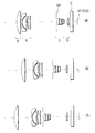
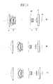
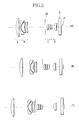
- FIG. 1 is a section view of a zoom lens which is Embodiment 1 of the present invention.
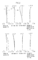
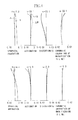
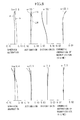
- FIG. 2 shows aberrations in Numerical Example 1 of the present invention
- FIG. 3 is a section view of a zoom lens which is Embodiment 2 of the present invention.
- FIG. 4 shows aberrations in Numerical Example 2 of the present invention
- FIG. 5 is a section view of a zoom lens which is Embodiment 3 of the present invention.
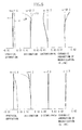
- FIG. 6 shows aberrations in Numerical Example 3 of the present invention
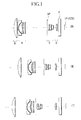
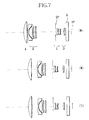
- FIG. 7 is a section view of a zoom lens which is Embodiment 4 of the present invention.
- FIG. 8 shows aberrations in Numerical Example 4 of the present invention
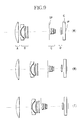
- FIG. 9 is a section view of a zoom lens which is Embodiment 5 of the present invention.
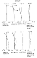
- FIG. 10 shows aberrations in Numerical Example 5 of the present invention
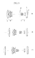
- FIG. 11 is a section view of a zoom lens which is Embodiment 6 of the present invention.
- FIG. 12 shows aberrations in Numerical Example 6 of the present invention.
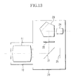
- FIG. 13 is a section view of a digital camera having the zoom lens of any of Embodiments 1 to 6.
- An image-taking apparatus which embodies the present invention uses a zoom lens according to any of Embodiment 1 to Embodiment 6 shown in FIGS. 1, 3 , 5 , 7 , 9 , and 11 to form an object image on a solid-state image pickup element (photoelectric conversion element) such as a CCD and a CMOS sensor disposed on an image plane IP.
- a solid-state image pickup element photoelectric conversion element
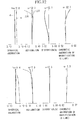
- FIGS. 1, 3 , and 5 are section views showing the zoom lenses of Embodiment 1 to Embodiment 3, in which (W) represents the wide angle end, (M) an middle zoom position, and (T) the telephoto end.
- W represents the wide angle end
- M represents the wide angle end
- T the telephoto end.
- letter A shows a first lens unit having a positive optical power (the optical power is the reciprocal of the focal length of the lens unit)
- letter B a second lens unit having a negative optical power
- letter C shows a third lens unit having a positive optical power
- letter D shows a fourth lens unit having a positive optical power.
- SP shows an aperture stop and G shows a glass block such as a optical filter or a face plate.
- the entire zoom lens system comprises at least four lens units, and zooming is provided by changing the spacing between the respective units on an optical axis.
- Embodiment 1 to Embodiment 3 for zooming from the wide angle end to the telephoto end, the spacing between the first lens unit A and the second lens unit B is increased, the spacing between the second lens unit B and the third lens unit C is reduced, and the spacing between the third lens unit C and the fourth lens unit D is increased.
- the aperture stop SP moves together with the third lens unit C.
- Cw represents the spacing between the third lens unit C and the fourth lens unit D on the optical axis at the wide angle end
- Ct represents the spacing between the third lens unit C and the fourth lens unit D on the optical axis at the telephoto end
- f 3 represents the focal length of the third lens unit C.
- the conditional expression (1) relates to the track of movement and the optical power of the third lens unit C. If the ratio of (Cw ⁇ Ct)/f 3 exceeds the upper limit in the conditional expression (1), the third lens unit C moves over an unacceptably long distance, and thus variations in the exit pupil cannot be suppressed. On the other hand, if the ratio is less than the lower limit, the third lens unit C has such a low optical power that it is difficult to reduce the overall length of the zoom lens.
- Embodiment 1 to Embodiment 3 for zooming from the wide angle end to the telephoto end, the third lens unit C moves toward the object side, and the fourth lens unit D moves along a track which is convex toward the object side.
- the following conditional expression is preferably satisfied:
- fw represents the focal length of the entire zoom lens system at the wide angle end
- f 4 represents the focal length of the fourth lens unit D.
- the conditional expression (2) relates to the optical power of the fourth lent unit D. If the ratio of fw/f 4 exceeds the upper limit in the conditional expression (2), the refractive power of the fourth lens unit D is so high that it is impossible to eliminate the influence of variations in the aperture stop SP, which moves together with the third lens unit C, exerting upon variations in the exit pupil. On the other hand, if the ratio is less than the lower limit, the optical power of the fourth lens unit D is so low that it is difficult to suppress variations in aberration in zooming which is advantageously small in the structure of the four lens unit.
- the first lens unit A and the second lens unit B are moved along a track which is convex toward the image side when zooming from the wide angle end to the telephoto end. As a result, variations in aberration can be reduced throughout the entire zoom range.
- the focal length of the fourth lens unit D preferably satisfies:
- the third lens unit C consists of a positive lens element, a cemented lens in which a positive lens element and a negative lens element are cemented, in order from the object side.
- the third lens unit C consists of a positive lens element, a cemented lens in which a positive lens element and a negative lens element are cemented, and a positive lens element, in order from the object side.
- the third lens unit C consists of a positive lens element, a cemented lens in which a positive lens element and a negative lens element are cemented, and a positive lens element, in order from the object side:
- f 3 r represents the focal length of the lens element closest to the image side of the third lens unit C.
- conditional expression (5) defines a proper range for maintaining a proper focal length of the lens closest to the image side of the third lens unit C to reduce variations in the emergent angle of light rays emerging from the third lens unit C.
- Embodiment 1 to Embodiment 3 are shown.
- a numerical example of Embodiment 1 shown in FIG. 1 is referred to as Numerical Example 1, a numerical example of Embodiment 2 in FIG. 3 as Numerical Example 2, and a numerical example of Embodiment 3 in FIG. 5 as Numerical Example 3.
- ri represents the radius of curvature of the i-th lens surface in order from the object side
- di represents the thickness of the i-th optical member in order from the object side or the air space corresponding thereto
- ni and vi represent the refractive index and the Abbe number of the material of the i-th optical member in order from the object side.
- R represents the radius of curvature of the center of the lens surface
- an X axis represents an optical axis direction (traveling direction of light)
- a Y axis represents a direction perpendicular to the optical axis
- a K represents the conic constant
- B, C, and D are aspheric coefficients.
- e-X means “x10 ⁇ x .”
- f represents a focal length
- fno represents a F number
- ⁇ represents half of the field angle.
- Table 4 shows the values calculated with the aforementioned conditional expressions (1) to (5) in Numerical Examples 1 to 3.
- FIGS. 2, 4 and 6 show aberrations in Numerical Examples 1 to 3, respectively.
- a curve d represents the aberration of a d line
- a curve g represents the aberration of a g line
- a curve ⁇ S represents the aberration on a sagittal image plane
- a curve ⁇ M represents the aberration on a meridional image plane, respectively.
- appropriately setting the arrangement of the optical powers in the respective lens units and the track of movement during zooming in the zoom lens of the four lens unit structure can provide favorable optical performance at an arbitrary zoom position and can reduce variations in the exit pupil distance throughout the entire zoom range.
- Embodiment 4 to Embodiment 6 are described.
- FIGS. 7, 9 , and 11 are section views showing lenses of zoom lenses of Embodiment 4 to Embodiment 6, in which (W) represents the wide angle end, (M) an middle zoom position, and (T) the telephoto end.
- W represents the wide angle end
- M an middle zoom position
- T the telephoto end.
- letter A shows a first lens unit having a positive optical power
- letter B shows a second lens unit having a negative optical power
- letter C shows a third lens unit having a positive optical power
- letter D shows a fourth lens unit having a positive optical power.
- SP shows an aperture stop and G shows a glass block such as an optical filter or a face plate.
- the entire zoom lens system comprises four lens units, and zooming is provided by changing the spacing between the respective units on an optical axis.
- the moving direction of the second lens unit B is reversed to follow a convex track toward the image side while zooming from the wide angle end to the telephoto end.
- the spacing margin between the second lens unit B and the third lens unit C can be reduced to achieve a reduction in size of the entire zoom lens system.
- bwt represents an amount of movement of the second lens unit B from the wide angle end to the telephoto end.
- the conditional expression (6) relates to the moving amount of the second lens unit B in zooming. If the ratio of bwm/bwt exceeds the upper limit in the conditional expression (6), the second lens unit B moves over a large distance in the portion of the zoom region from the wide angle end to the middle point, making it difficult to achieve high zoom ratio of the entire zoom lens system. On the other hand, if the ratio of bwm/bwt is less than the lower limit, favorable correction of aberration is difficult to achieve in the middle zoom range.
- fw represents the focal length of the entire zoom lens system at the wide angle end
- f 1 represents the focal length of the first lens unit A.
- the conditional expression (7) relates to the focal length of the first lens unit A. If the ratio of fw/f 1 exceeds the upper limit in the conditional expression (7), the first lens unit A has such a high power that the diameter of the first lens unit A is large. On the other hand, if the ratio is less than the lower limit, the first lens unit A disadvantageously has a low power to increase the overall length of the zoom lens required for a desired zoom ratio.
- the first lens unit A is formed as a movable unit, and the overall length of the zoom lens at the telephoto end is set to be larger than the overall length of the zoom lens at the wide angle end. It is thus possible to reduce the burden of variable magnification on the other lens units.
- the moving direction of the first lens unit A is reversed to follow a convex track toward the image side while zooming from the wide angle end to the telephoto end. This enables reduced variations in optical performance while zooming and a smaller diameter of the first lens unit A.
- the third lens unit C is moved monotonously toward the object side (in such a manner that the moving direction is not changed) when zooming from the wide angle end to the telephoto end, and the fourth lens unit D is moved along a convex track toward the object side.
- optical performance can be enhanced throughout the entire zoom range in addition to a reduction in the burden of variable magnification on the second lens unit B.
- Cw represents the spacing between the third lens unit C and the fourth lens unit D on the optical axis at the wide angle end
- Ct the spacing between the third lens unit C and the fourth lens unit D on the optical axis at the telephoto end
- Cm the spacing between the third lens unit C and the fourth lens unit D on the optical axis at the focal length fm of the entire zoom lens system
- fi the focal length of the i-th lens unit
- Both of the conditional expressions (8) and (9) relate to the arrangement of the optical power of the third lens unit C, and are important to appropriate burden sharing of variable magnification between the second lens unit B and the third lens unit C to achieve higher performance.
- the aperture stop SP is moved together with the third lens unit C to facilitate simplification of the structure of a lens barrel (not shown) for accommodating this zoom lens.
- Embodiment 4 to Embodiment 6 are shown.
- a numerical example of Embodiment 4 shown in FIG. 7 is referred to as Numerical Example 4, a numerical example of Embodiment 5 in FIG. 9 as Numerical Example 5, and a numerical example of Embodiment 6 in FIG. 11 as Numerical Example 6.
- Table 8 shows the values calculated with the aforementioned conditional expressions (6) to (9) in Numerical Examples 4 to 6.
- FIGS. 8, 10 and 12 show aberrations in Numerical Examples 4 to 6.
- a curve d represents the aberration of a d line
- a curve g represents the aberration of a g line
- a curve ⁇ S represents the aberration on a sagittal image plane
- a curve ⁇ M represents the aberration on a meridional image plane, respectively.
- FIG. 13 shows a digital still camera which uses the zoom lens of any of Embodiment 1 to Embodiment 6 described above.
- reference numeral 10 shows a zoom lens including an image-taking optical system 11
- 20 shows a camera unit
- 21 a quick return mirror
- 22 shows a focusing screen
- 23 shows a pentaprism
- 24 shows an eyepiece.
- Reference numeral 25 shows a solid-state image pickup element (photoelectric conversion element) such as a CCD and a CMOS sensor.
- the solid-state image pickup element 25 photoelectrically converts an object image formed by the image-taking optical system 11 (zoom lens 10 ).
- the quick return mirror 21 disposed on an image-taking optical path directs a part of light rays from the object to the focusing screen 22 , pentaprism 23 , and the eyepiece 24 , which constitute a viewfinder optical system, to allow optical observation of the object image.
- the light rays from the object passing through a half mirror section of the quick return mirror 21 is photoelectrically converted by the image pickup element 25 , and the resulting image signal is displayed on an LCD or the like, not shown, to allow electrical observation of the object image.
- the quick return mirror 21 is retracted from the image-taking optical path, and the light rays from the object (the object image) is photoelectrically converted by the image pickup element 25 , and the resulting image information is stored in a storage media, not shown.
- the zoom lens of each of the aforementioned embodiments can be used not only in the digital still camera shown in FIG. 13 but also as a zoom lens for a video camera.
Landscapes
- Physics & Mathematics (AREA)
- General Physics & Mathematics (AREA)
- Optics & Photonics (AREA)
- Lenses (AREA)
Abstract
A zoom lens comprising four lens units is disclosed which achieves a high variable magnification ratio and favorable optical performance at an arbitrary zoom position. The zoom lens of the present invention includes, in order from an object side, a first lens unit having positive optical power, a second lens unit having a negative optical power, a third lens unit having a positive optical power, and a fourth lens unit having a positive optical power. During zooming from the wide angle end to the telephoto end, the spacing between the first and second lens units is increased, the spacing between the second and third lens units is decreased, the spacing between the third and fourth lens units is increased, and an aperture stop moves together with the third lens unit. In addition, specific conditions are satisfied.
Description
1. Field of the Invention
The present invention relates to a zoom lens, and more particularly, to a zoom lens which is preferable for use in an image-taking apparatus such as a video camera and a digital camera which uses a solid-state image pickup element as an image pickup device.
2. Description of the Related Art
Conventionally, a zoom lens of a so-called negative lead type having a lens unit with a negative optical power at the front has been used as a standard zoom lens in many cameras since it relatively easily achieves image taking at a wider angle.
As an exemplary standard zoom lens of this type, Japanese Patent Application Laid-Open No. 1978-132360 (corresponding to U.S. Pat. No. No.4,299,452), Japanese Patent Application Laid-Open No. 1981-19022 (corresponding to U.S. Pat. No. 4,370,031), and U.S. Pat. No. 5,283,639 each have proposed or disclosed a so-called two unit zoom lens consisting of two lens units, that is, a first lens unit having a negative optical power and a second lens unit having a positive optical power, in which these two lens units are moved along an optical axis to change the spacing between the lens units to provide zooming.
Japanese Patent Application Laid-Open No. 1995-52256 has proposed a zoom lens having, in order from an object side, a first lens unit having a negative optical power, a second lens unit having a positive optical power, and a third lens unit having a positive optical power, in which the spacing between the second lens unit and the third lens unit is increased to provide zooming from the wide angle end to the telephoto end.
In addition, U.S. Pat. No. 5,434,710 has disclosed a zoom lens having, in order from an object side, three lens units consisting of a first lens unit having a negative optical power, a second lens unit having a positive optical power, and a third lens unit having a positive optical power, in which the spacing between the second lens unit and the third lens unit is reduced to provide zooming from the wide angle end to the telephoto end.
The present inventor has also proposed a multiunit zoom lens comprising of three or more lens units in Japanese Patent Application Laid-Open No. 1994-27377 (corresponding to U.S. Pat. No. 6,104,548).
Typically, the negative lead type zoom lens having a lens unit with a negative optical power at the front is characterized in that image taking is relatively easily performed at a wider angle and that a predetermined back focal distance can be readily provided.
To achieve favorable optical performance throughout the zoom range or throughout an image plane, it is necessary to appropriately set the arrangement of the optical powers of respective lens units and the shapes of lenses.
Inappropriately setting the arrangement of the optical powers of the respective lens units and the lens shapes increases variations in aberration associated with to cause difficulty in providing high optical performance throughout the zoom range.
Especially, in the two unit zoom lens having a lens unit with a negative optical power at the front, the relative positions of the respective lens units on an optical axis are uniquely determined resulting from varied magnification and corrected variations in the position of an image plane. As a result, optical performance cannot be controlled arbitrarily at a certain position while zooming from the wide angle end to the telephoto end.
Variations in aberration need to be minimized in the respective lens units during zooming in order to provide favorable optical performance at a certain point during zooming. As a method to address this, for example, the optical power is reduced in each lens unit, or a larger number of lens elements are used to form each lens unit. These methods, however, lead to an increase in the overall length of the lenses and difficulty in achieving high zooming ratio and high performance.
To solve the problems, U.S. Pat. No. 5,570,233 has disclosed a zoom lens consisting of, in order from an object side, a first lens unit having a positive optical power, a second lens unit having a negative optical power, a third lens unit having a positive optical power, and a fourth lens unit having a positive optical power, in which each lens unit is moved to provide zooming.
With the development of the image pickup device, however, further improvement in optical performance is required in the field of optical apparatuses such as a video camera and a digital camera in which increasingly higher performance is desired.
Additionally, in a zoom lens of a type in which a lens unit closer to an image plane than an aperture stop moves in association with zooming, the exit pupil distance largely varies as a higher zooming ratio is provided. In a CCD frequently used as an image pickup device in recent years, for example, if the incident angle of light rays on an imaging plane varies, the angle of the light rays passing through a color filter is changed to create the possibility of causing a problem of color bleeding on the periphery of an image.
It is an object of the present invention to provide a zoom lens comprising four lens units which achieves a high zoom ratio and provides favorable optical performance at an arbitrary zoom position.
It is another object of the present invention to provide a zoom lens which involves small variations in the exit pupil distance during zooming, in addition to the aforementioned object.
To achieve the aforementioned objects, the zoom lens according to an aspect of the present invention includes, in order from an object side to an image side, a first lent unit which has a positive optical power, a second lens unit which has a negative optical power, a third lens unit which has a positive optical power, and a fourth lens unit which has a positive optical power. During zooming from the wide angle end to the telephoto end, the spacing between the first lens unit and the second lens unit is increased, the spacing between the second lens unit and the third lens unit is reduced, the spacing between the third lens unit and the fourth lens unit is increased, and an aperture stop moves together with the third lens unit. In addition, specific conditions described in the following embodiments are satisfied.
According to another aspect of the present invention, the zoom lens includes, in order from an object side to an image side, a first lens unit which has a positive optical power, a second lens unit which has a negative optical power, a third lens unit which has a positive optical power, and a fourth lens unit which has a positive optical power. The spacing between the respective lens units changes during zooming, and specific conditions described in the following embodiments are satisfied.
Characteristics of the zoom lens of the present invention will be apparent from the following description of specific embodiments with reference to the drawings.
FIG. 1 is a section view of a zoom lens which is Embodiment 1 of the present invention;
FIG. 2 shows aberrations in Numerical Example 1 of the present invention;
FIG. 3 is a section view of a zoom lens which is Embodiment 2 of the present invention;
FIG. 4 shows aberrations in Numerical Example 2 of the present invention;
FIG. 5 is a section view of a zoom lens which is Embodiment 3 of the present invention;
FIG. 6 shows aberrations in Numerical Example 3 of the present invention;
FIG. 7 is a section view of a zoom lens which is Embodiment 4 of the present invention;
FIG. 8 shows aberrations in Numerical Example 4 of the present invention;
FIG. 9 is a section view of a zoom lens which is Embodiment 5 of the present invention;
FIG. 10 shows aberrations in Numerical Example 5 of the present invention;
FIG. 11 is a section view of a zoom lens which is Embodiment 6 of the present invention;
FIG. 12 shows aberrations in Numerical Example 6 of the present invention; and
FIG. 13 is a section view of a digital camera having the zoom lens of any of Embodiments 1 to 6.
Preferred embodiments of the present invention are hereinafter described with reference to the drawings.
An image-taking apparatus which embodies the present invention uses a zoom lens according to any of Embodiment 1 to Embodiment 6 shown in FIGS. 1, 3, 5, 7, 9, and 11 to form an object image on a solid-state image pickup element (photoelectric conversion element) such as a CCD and a CMOS sensor disposed on an image plane IP.
First of all, description is made for zoom lenses according to Embodiment 1 to Embodiment 3 shown in FIGS. 1, 3, and 5.
FIGS. 1, 3, and 5 are section views showing the zoom lenses of Embodiment 1 to Embodiment 3, in which (W) represents the wide angle end, (M) an middle zoom position, and (T) the telephoto end. In each section view, in order from an object side (the left side in each figure), letter A shows a first lens unit having a positive optical power (the optical power is the reciprocal of the focal length of the lens unit), letter B a second lens unit having a negative optical power, letter C shows a third lens unit having a positive optical power, and letter D shows a fourth lens unit having a positive optical power.
SP shows an aperture stop and G shows a glass block such as a optical filter or a face plate.
In the zoom lens in each of Embodiment 1 to Embodiment 3, the entire zoom lens system comprises at least four lens units, and zooming is provided by changing the spacing between the respective units on an optical axis.
In Embodiment 1 to Embodiment 3, for zooming from the wide angle end to the telephoto end, the spacing between the first lens unit A and the second lens unit B is increased, the spacing between the second lens unit B and the third lens unit C is reduced, and the spacing between the third lens unit C and the fourth lens unit D is increased. The aperture stop SP moves together with the third lens unit C.
Each zoom lens system in Embodiment 1 to 3 satisfies the following conditional expression:
−1.0<(Cw−Ct)/ f 3<−0.6 (1)
where Cw represents the spacing between the third lens unit C and the fourth lens unit D on the optical axis at the wide angle end, Ct represents the spacing between the third lens unit C and the fourth lens unit D on the optical axis at the telephoto end, and f3 represents the focal length of the third lens unit C.
The conditional expression (1) relates to the track of movement and the optical power of the third lens unit C. If the ratio of (Cw−Ct)/f3 exceeds the upper limit in the conditional expression (1), the third lens unit C moves over an unacceptably long distance, and thus variations in the exit pupil cannot be suppressed. On the other hand, if the ratio is less than the lower limit, the third lens unit C has such a low optical power that it is difficult to reduce the overall length of the zoom lens.
In Embodiment 1 to Embodiment 3, for zooming from the wide angle end to the telephoto end, the third lens unit C moves toward the object side, and the fourth lens unit D moves along a track which is convex toward the object side. The following conditional expression is preferably satisfied:
where fw represents the focal length of the entire zoom lens system at the wide angle end, and f4 represents the focal length of the fourth lens unit D.
The conditional expression (2) relates to the optical power of the fourth lent unit D. If the ratio of fw/f4 exceeds the upper limit in the conditional expression (2), the refractive power of the fourth lens unit D is so high that it is impossible to eliminate the influence of variations in the aperture stop SP, which moves together with the third lens unit C, exerting upon variations in the exit pupil. On the other hand, if the ratio is less than the lower limit, the optical power of the fourth lens unit D is so low that it is difficult to suppress variations in aberration in zooming which is advantageously small in the structure of the four lens unit.
To maintain a small overall length of the zoom lens, it is preferable that the first lens unit A and the second lens unit B are moved along a track which is convex toward the image side when zooming from the wide angle end to the telephoto end. As a result, variations in aberration can be reduced throughout the entire zoom range.
In addition, the focal length of the fourth lens unit D preferably satisfies:
when the third lens unit C consists of a positive lens element, a cemented lens in which a positive lens element and a negative lens element are cemented, in order from the object side.
Furthermore, the following conditional expression is preferably satisfied:
when the third lens unit C consists of a positive lens element, a cemented lens in which a positive lens element and a negative lens element are cemented, and a positive lens element, in order from the object side.
More preferably, the following conditional expression is satisfied when the third lens unit C consists of a positive lens element, a cemented lens in which a positive lens element and a negative lens element are cemented, and a positive lens element, in order from the object side:
where f3r represents the focal length of the lens element closest to the image side of the third lens unit C.
The conditional expression (5) defines a proper range for maintaining a proper focal length of the lens closest to the image side of the third lens unit C to reduce variations in the emergent angle of light rays emerging from the third lens unit C.
Next, numerical examples of Embodiment 1 to Embodiment 3 are shown. A numerical example of Embodiment 1 shown in FIG. 1 is referred to as Numerical Example 1, a numerical example of Embodiment 2 in FIG. 3 as Numerical Example 2, and a numerical example of Embodiment 3 in FIG. 5 as Numerical Example 3.
In each numerical example, ri represents the radius of curvature of the i-th lens surface in order from the object side, di represents the thickness of the i-th optical member in order from the object side or the air space corresponding thereto, and ni and vi represent the refractive index and the Abbe number of the material of the i-th optical member in order from the object side.
When a lens surface is an aspheric shape, the aspheric shape is represented by the following expression: 
where R represents the radius of curvature of the center of the lens surface, an X axis represents an optical axis direction (traveling direction of light), a Y axis represents a direction perpendicular to the optical axis, a K represents the conic constant, and B, C, and D, are aspheric coefficients. “e-X” means “x10−x.” Furthermore, in each numerical example, f represents a focal length, fno represents a F number, and ω represents half of the field angle.
| TABLE 1 |
| f = 7.46779 fno = 1:2.7 2ω = 63.2 |
| r1 = 35.389 | d1 = 5.50 | n1 = 1.51633 | ν1 = 64.1 |
| r2 = −528.126 | d2 = VARIABLE | ||
| r3 = 71.708 | d3 = 1.30 | n2 = 1.80400 | ν2 = 46.6 |
| r4 = 11.296 | d4 = 5.50 | ||
| r5 = −73.005 | d5 = 1.00 | n3 = 1.77250 | ν3 = 49.6 |
| r6 = 27.283 | d6 = 1.70 | ||
| r7 = 21.795 | d7 = 2.80 | n4 = 1.84666 | ν4 = 23.9 |
| r8 = 103.969 | d8 = VARIABLE | ||
| r9 = ∞ (APERA- | d9 = 0.80 | ||
| TURE STOP) | |||
| r10 = 9.786 | d10 = 2.80 | n5 = 1.72916 | ν5 = 54.7 |
| r11 = 54.605 | d11 = 0.30 | ||
| r12 = 12.273 | d12 = 2.40 | n6 = 1.69350 | ν6 = 53.2 |
| r13 = 25.204 | d13 = 0.70 | n7 = 1.84666 | ν7 = 23.9 |
| r14 = 7.182 | d14 = 2.20 | ||
| r15 = −81.570 | d15 = 1.40 | n8 = 1.51633 | ν8 = 64.1 |
| r16 = −24.163 | d16 = VARIABLE | ||
| r17 = 28.000 | d17 = 2.00 | n9 = 1.80610 | ν9 = 40.7 |
| r18 = −1242.352 | d18 = VARIABLE | ||
| r19 = ∞ | d19 = 4.00 | n10 = 1.51680 | ν10 = 64.2 |
| r20 = ∞ | |||
| FOCAL LENGTH/VARIABLE SPACING | 7.47 | 16.47 | 36.29 |
| d2 | 1.20 | 10.92 | 18.54 |
| d8 | 37.10 | 15.13 | 3.55 |
| d16 | 4.06 | 7.91 | 22.43 |
| d18 | 2.00 | 4.36 | 4.91 |
| ASPHERIC SURFACE | ||
| 12TH SURFACE | |||
| R = 12.273 | K = 6.160E−1 | B = −1.849E−4 | C = −1.558E−6 |
| D = −2.399E−8 | |||
| 17TH SURFACE | |||
| R = 28.0 | K = 3.407E−1 | B = −1.954E−6 | C = 9.748E−8 |
| D = −3.041E−9 | |||
| TABLE 2 |
| f = 7.45587 fno = 1:2.8 2ω = 66.2 |
| r1 = 33.880 | d1 = 6.00 | n1 = 1.51633 | ν1 = 64.1 |
| r2 = −7025.879 | d2 = VARIABLE | ||
| r3 = 54.832 | d3 = 1.30 | n2 = 1.80400 | ν2 = 46.6 |
| r4 = 11.212 | d4 = 5.93 | ||
| r5 = −72.278 | d5 = 1.00 | n3 = 1.77250 | ν3 = 49.6 |
| r6 = 28.966 | d6 = 1.70 | ||
| r7 = 22.856 | d7 = 2.80 | n4 = 1.84666 | ν4 = 23.9 |
| r8 = 103.245 | d8 = VARIABLE | ||
| r9 = ∞ (APERA- | d9 = 0.80 | ||
| TURE STOP) | |||
| r10 = 9.193 | d10 = 2.80 | n5 = 1.69680 | ν5 = 55.5 |
| r11 = 224.107 | d11 = 0.30 | ||
| r12 = 12.293 | d12 = 2.40 | n6 = 1.69350 | ν6 = 53.2 |
| r13 = 26.680 | d13 = 0.70 | n7 = 1.84666 | ν7 = 23.9 |
| r14 = 6.690 | d14 = VARIABLE | ||
| r15 = 20.006 | d15 = 2.00 | n8 = 1.80610 | ν8 = 40.7 |
| r16 = 594.211 | d16 = VARIABLE | ||
| r17 = ∞ | d17 = 4.00 | n9 = 1.51633 | ν9 = 64.2 |
| r18 = ∞ | |||
| FOCAL LENGTH/VARIABLE SPACING | 7.46 | 16.45 | 36.32 |
| d2 | 1.00 | 10.93 | 20.76 |
| d8 | 37.42 | 14.90 | 3.57 |
| d14 | 6.73 | 10.17 | 22.87 |
| d16 | 2.00 | 4.56 | 5.72 |
| ASPHERIC SURFACE | ||
| 12TH SURFACE | |||
| R = 12.29 | K = 4.853E−3 | B = −1.833E−4 | C = −2.283E−6 |
| D = −3.066E−8 | |||
| 15TH SURFACE | |||
| R = 20.01 | K = 2.087 | B = −4.443E−5 | C = −2.156E−8 |
| D = −5.081E−9 | |||
| TABLE 3 |
| f = 7.44598 fno = 1:2.8 2ω = 65.4 |
| r1 = 36.174 | d1 = 5.50 | n1 = 1.51633 | ν1 = 64.2 |
| r2 = −2716.614 | d2 = VARIABLE | ||
| r3 = 50.435 | d3 = 1.30 | n2 = 1.77250 | ν2 = 49.6 |
| r4 = 10.608 | d4 = 4.70 | ||
| r5 = 198.546 | d5 = 1.00 | n3 = 1.77250 | ν3 = 49.6 |
| r6 = 16.816 | d6 = 1.70 | ||
| r7 = 15.988 | d7 = 2.80 | n4 = 1.84666 | ν4 = 23.9 |
| r8 = 37.416 | d8 = VARIABLE | ||
| r9 = ∞ (APERA- | d9 = 2.30 | ||
| TURE STOP) | |||
| r10 = 9.853 | d10 = 2.80 | n5 = 1.74330 | ν5 = 49.3 |
| r11 = −422.142 | d11 = 0.30 | ||
| r12 = 11.114 | d12 = 2.40 | n6 = 1.69680 | ν6 = 55.5 |
| r13 = 38.099 | d13 = 0.70 | n7 = 1.84666 | ν7 = 23.9 |
| r14 = 6.158 | d14 = 2.00 | ||
| r15 = 254.815 | d15 = 1.40 | n8 = 1.60311 | ν8 = 60.7 |
| r16 = −146.162 | d16 = VARIABLE | ||
| r17 = 16.773 | d17 = 3.40 | n9 = 1.73077 | ν9 = 40.5 |
| r18 = −25.584 | d18 = 0.70 | n10 = 1.69680 | ν10 = 55.5 |
| r19 = 96.538 | d19 = VARIABLE | ||
| r20 = ∞ | d20 = 4.00 | n11 = 1.51680 | ν11 = 64.2 |
| r21 = ∞ | |||
| FOCAL LENGTH/VARIABLE SPACING | 7.45 | 16.61 | 37.00 |
| d2 | 2.00 | 11.42 | 23.20 |
| d8 | 30.00 | 10.07 | 1.80 |
| d16 | 3.62 | 6.80 | 19.61 |
| d19 | 3.04 | 6.02 | 6.39 |
| ASPHERIC SURFACE | ||
| 10TH SURFACE | |||
| R = 9.853 | K = −2.505 | B = 2.312E−4 | C = −1.947E−6 |
| D = 4.993E−8 | E = −1.152E−9 | ||
| 17TH SURFACE | |||
| R = 16.774 | K = 8.657E−1 | B = −3.579E−5 | C = 1.114E−7 |
| D = −1.522E−9 | E = 2.917E−10 | ||
Table 4 shows the values calculated with the aforementioned conditional expressions (1) to (5) in Numerical Examples 1 to 3.
| TABLE 4 | ||||
| Numerical | Numerical | Numerical | ||
| Example 1 | Example 2 | Example 3 | ||
| Conditional | −0.84 | −0.72 | −0.82 | ||
| expression (1) | |||||
| conditional | 0.22 | 0.29 | 0.29 | ||
| expressions (2) to (4) | |||||
| conditional | 0.33 | — | 0.13 | ||
| expression (5) | |||||
FIGS. 2, 4 and 6 show aberrations in Numerical Examples 1 to 3, respectively. In each of the figures, a curve d represents the aberration of a d line, a curve g represents the aberration of a g line, a curve ΔS represents the aberration on a sagittal image plane, and a curve ΔM represents the aberration on a meridional image plane, respectively.
As described above, according to Embodiment 1 to Embodiment 3, appropriately setting the arrangement of the optical powers in the respective lens units and the track of movement during zooming in the zoom lens of the four lens unit structure can provide favorable optical performance at an arbitrary zoom position and can reduce variations in the exit pupil distance throughout the entire zoom range.
Next. Embodiment 4 to Embodiment 6 are described.
FIGS. 7, 9, and 11 are section views showing lenses of zoom lenses of Embodiment 4 to Embodiment 6, in which (W) represents the wide angle end, (M) an middle zoom position, and (T) the telephoto end. In each section view, in order from an object side (the left side in each figure), letter A shows a first lens unit having a positive optical power, letter B shows a second lens unit having a negative optical power, letter C shows a third lens unit having a positive optical power, and letter D shows a fourth lens unit having a positive optical power.
SP shows an aperture stop and G shows a glass block such as an optical filter or a face plate.
In the zoom lens in each of Embodiment 4 to Embodiment 6, the entire zoom lens system comprises four lens units, and zooming is provided by changing the spacing between the respective units on an optical axis.
Especially, the moving direction of the second lens unit B is reversed to follow a convex track toward the image side while zooming from the wide angle end to the telephoto end. Thus, the spacing margin between the second lens unit B and the third lens unit C can be reduced to achieve a reduction in size of the entire zoom lens system.
In each of Embodiment 4 to Embodiment 6, the following is satisfied:
where bwm represents an amount of movement of the second lens unit B from the wide angle end to the position where the focal length fm of the entire zoom lens system is equal to the geometric mean 
of the focal length fw at the wide angle end and the focal length ft at the telephoto end, and bwt represents an amount of movement of the second lens unit B from the wide angle end to the telephoto end.
The conditional expression (6) relates to the moving amount of the second lens unit B in zooming. If the ratio of bwm/bwt exceeds the upper limit in the conditional expression (6), the second lens unit B moves over a large distance in the portion of the zoom region from the wide angle end to the middle point, making it difficult to achieve high zoom ratio of the entire zoom lens system. On the other hand, if the ratio of bwm/bwt is less than the lower limit, favorable correction of aberration is difficult to achieve in the middle zoom range.
In each of Embodiment 4 to Embodiment 6, appropriate arrangement of optical powers enables improved optical performance in the middle of zooming. In addition, when the first lens unit A consists of a single positive lens element, it is possible to provide both a reduced size of the entire zoom lens system and favorable correction of aberration.
In each of Embodiment 4 to Embodiment 6, the following conditional expression needs to be satisfied to form the first lens unit A of the single positive lens element:
where fw represents the focal length of the entire zoom lens system at the wide angle end, and f1 represents the focal length of the first lens unit A.
The conditional expression (7) relates to the focal length of the first lens unit A. If the ratio of fw/f1 exceeds the upper limit in the conditional expression (7), the first lens unit A has such a high power that the diameter of the first lens unit A is large. On the other hand, if the ratio is less than the lower limit, the first lens unit A disadvantageously has a low power to increase the overall length of the zoom lens required for a desired zoom ratio.
In addition, the first lens unit A is formed as a movable unit, and the overall length of the zoom lens at the telephoto end is set to be larger than the overall length of the zoom lens at the wide angle end. It is thus possible to reduce the burden of variable magnification on the other lens units.
The moving direction of the first lens unit A is reversed to follow a convex track toward the image side while zooming from the wide angle end to the telephoto end. This enables reduced variations in optical performance while zooming and a smaller diameter of the first lens unit A.
The third lens unit C is moved monotonously toward the object side (in such a manner that the moving direction is not changed) when zooming from the wide angle end to the telephoto end, and the fourth lens unit D is moved along a convex track toward the object side. Thus, optical performance can be enhanced throughout the entire zoom range in addition to a reduction in the burden of variable magnification on the second lens unit B.
To further enhance the performance, in each of Embodiment 4 to Embodiment 6, the following is preferably satisfied:
−0.9<f 2 /f 3(or f 3 /fw)<−0.6 (9)
where Cw represents the spacing between the third lens unit C and the fourth lens unit D on the optical axis at the wide angle end, Ct the spacing between the third lens unit C and the fourth lens unit D on the optical axis at the telephoto end, Cm the spacing between the third lens unit C and the fourth lens unit D on the optical axis at the focal length fm of the entire zoom lens system, and fi the focal length of the i-th lens unit.
Both of the conditional expressions (8) and (9) relate to the arrangement of the optical power of the third lens unit C, and are important to appropriate burden sharing of variable magnification between the second lens unit B and the third lens unit C to achieve higher performance.
The aperture stop SP is moved together with the third lens unit C to facilitate simplification of the structure of a lens barrel (not shown) for accommodating this zoom lens.
Next, numerical examples of Embodiment 4 to Embodiment 6 are shown. A numerical example of Embodiment 4 shown in FIG. 7 is referred to as Numerical Example 4, a numerical example of Embodiment 5 in FIG. 9 as Numerical Example 5, and a numerical example of Embodiment 6 in FIG. 11 as Numerical Example 6.
In Numerical Examples 4 to 6, the definitions of reference symbols and the expression for representing an aspheric lens surface are identical to those in Numerical Examples 1 to 3 described above.
| TABLE 5 |
| f = 7.45587 fno = 1:2.8 2ω = 66.2 |
| r1 = 33.880 | d1 = 6.00 | n1 = 1.51633 | ν1 = 64.1 |
| r2 = −7025.879 | d2 = VARIABLE | ||
| r3 = 54.832 | d3 = 1.30 | n2 = 1.80400 | ν2 = 46.6 |
| r4 = 11.212 | d4 = 5.93 | ||
| r5 = −72.278 | d5 = 1.00 | n3 = 1.77250 | ν3 = 49.6 |
| r6 = 28.966 | d6 = 1.70 | ||
| r7 = 22.856 | d7 = 2.80 | n4 = 1.84666 | ν4 = 23.9 |
| r8 = 103.245 | d8 = VARIABLE | ||
| r9 = ∞ (APERA- | d9 = 0.80 | ||
| TURE STOP) | |||
| r10 = 9.193 | d10 = 2.80 | n5 = 1.69680 | ν5 = 55.5 |
| r11 = 224.107 | d11 = 0.30 | ||
| r12 = 12.293 | d12 = 2.40 | n6 = 1.69350 | ν6 = 53.2 |
| r13 = 26.680 | d13 = 0.70 | n7 = 1.84666 | ν7 = 23.9 |
| r14 = 6.690 | d14 = VARIABLE | ||
| r15 = 20.006 | d15 = 2.00 | n8 = 1.80610 | ν8 = 40.7 |
| r16 = 594.211 | d16 = VARIABLE | ||
| r17 = ∞ | d17 = 4.00 | n9 = 1.51633 | ν9 = 64.2 |
| r18 = ∞ | |||
| FOCAL LENGTH/VARIABLE SPACING | 7.46 | 16.45 | 36.32 |
| d2 | 1.00 | 10.93 | 20.76 |
| d8 | 37.42 | 14.90 | 3.57 |
| d14 | 6.73 | 10.17 | 22.87 |
| d16 | 2.00 | 4.56 | 5.72 |
| ASPHERIC SURFACE | ||
| 12TH SURFACE | |||
| R = 12.29 | K = 4.853E−3 | B = −1.833E−4 | C = −2.283E−6 |
| D = −3.066E−8 | |||
| 17TH SURFACE | |||
| R = 20.01 | K = 2.087 | B = −4.443E−5 | C = −2.156E−8 |
| D = 5.081E−9 | |||
| TABLE 6 |
| f = 7.45587 fno = 1:2.6 2ω = 66.4 |
| r1 = 40.266 | d1 = 6.00 | n1 = 1.48749 | ν1 = 70.2 |
| r2 = −734.702 | d2 = VARIABLE | ||
| r3 = 76.424 | d3 = 1.30 | n2 = 1.80400 | ν2 = 46.6 |
| r4 = 11.861 | d4 = 5.35 | ||
| r5 = −67.123 | d5 = 1.00 | n3 = 1.77250 | ν3 = 49.6 |
| r6 = 31.704 | d6 = 1.70 | ||
| r7 = 23.332 | d7 = 2.80 | n4 = 1.84666 | ν4 = 23.9 |
| r8 = 100.885 | d8 = VARIABLE | ||
| r9 = ∞ (APERA- | d9 = 0.80 | ||
| TURE STOP) | |||
| r10 = 9.818 | d10 = 2.80 | n5 = 1.69680 | ν5 = 55.5 |
| r11 = 87.682 | d11 = 0.30 | ||
| r12 = 12.726 | d12 = 2.40 | n6 = 1.69350 | ν6 = 53.2 |
| r13 = 20.514 | d13 = 0.70 | n7 = 1.84666 | ν7 = 23.9 |
| r14 = 7.404 | d14 = 1.80 | ||
| r15 = −66.106 | d15 = 1.40 | n8 = 1.51633 | ν8 = 64.1 |
| r16 = −18.575 | d16 = VARIABLE | ||
| r17 = 19.325 | d17 = 2.00 | n9 = 1.80610 | ν9 = 40.7 |
| r18 = 45.742 | d18 = VARIABLE | ||
| r19 = ∞ | d19 = 4.00 | n10 = 1.51880 | ν10 = 64.2 |
| r20 = ∞ | |||
| FOCAL LENGTH/VARIABLE SPACING | 7.46 | 16.45 | 36.32 |
| d2 | 3.00 | 18.82 | 20.14 |
| d8 | 39.19 | 19.06 | 3.58 |
| d16 | 9.80 | 13.15 | 28.28 |
| d18 | 2.00 | 2.96 | 2.00 |
| ASPHERIC SURFACE | ||
| 12TH SURFACE | |||
| R = 12.726 | K = 5.664E−1 | B = −1.891E−4 | C = −1.7595−6 |
| D = −1.421E−8 | |||
| 17TH SURFACE | |||
| R = 19.325 | K = −5.355 | B = 7.372E−5 | C = 1.514E−6 |
| D = −2.911E−8 | |||
| TABLE 7 |
| f = 7.44598 fno = 1:22.8 2ω = 65.4 |
| r1 = 36.74 | d1 = 5.50 | n1 = 1.51633 | ν1 = 64.2 |
| r2 = −2716.614 | d2 = VARIABLE | ||
| r3 = 50.435 | d3 = 1.30 | n2 = 1.77250 | ν2 = 49.6 |
| r4 = 10.608 | d4 = 4.70 | ||
| r5 = 198.546 | d5 = 1.00 | n3 = 1.77250 | ν3 = 49.6 |
| r6 = 16.816 | d6 = 1.70 | ||
| r7 = 15.988 | d7 = 2.80 | n4 = 1.84666 | ν4 = 23.9 |
| r8 = 37.416 | d8 = VARIABLE | ||
| r9 = ∞ (APERA- | d9 = 2.30 | ||
| TURE STOP) | |||
| r10 = 9.853 | d10 = 2.80 | n5 = 1.74330 | ν5 = 49.3 |
| r11 = −422.142 | d11 = 0.30 | ||
| r12 = 11.114 | d12 = 2.40 | n6 = 1.69680 | ν6 = 55.5 |
| r13 = 38.099 | d13 = 0.70 | n7 = 1.84666 | ν7 = 23.9 |
| r14 = 6.158 | d14 = 2.00 | ||
| r15 = 254.815 | d15 = 1.40 | n8 = 1.60311 | ν8 = 60.7 |
| r16 = −146.162 | d16 = VARIABLE | ||
| r17 = 16.773 | d17 = 3.40 | n9 = 1.73077 | ν9 = 40.5 |
| r18 = −25.584 | d18 = 0.70 | n10 = 1.69680 | ν10 = 55.5 |
| r19 = 96.538 | d19 = VARIABLE | ||
| r20 = ∞ | d20 = 4.00 | n11 = 1.51680 | ν11 = 64.2 |
| r21 = ∞ | |||
| FOCAL LENGTH/VARIABLE SPACING | 7.45 | 16.61 | 37.00 |
| d2 | 2.00 | 11.42 | 23.20 |
| d8 | 30.00 | 10.07 | 1.80 |
| d16 | 3.62 | 6.80 | 19.61 |
| d19 | 3.04 | 6.07 | 6.39 |
| ASPHERIC SURFACE | ||
| 10TH SURFACE | |||
| R = 9.853 | K = −2.505 | B = 2.312E−4 | C = −1.947E−6 |
| D = 4.993E−8 | E = −1.152E−9 | ||
| 17TH SURFACE | |||
| R = 16.774 | K = 8.657E·1 | B = −3.579E−5 | C = 1.114E−7 |
| D = −1.522E−9 | E = 2.917E−10 | ||
Table 8 shows the values calculated with the aforementioned conditional expressions (6) to (9) in Numerical Examples 4 to 6.
| TABLE 8 | ||||
| Numerical | Numerical | Numerical | ||
| Example 4 | Example 5 | Example 6 | ||
| conditional | 1.18 | 0.92 | 1.55 |
| expression (6) | |||
| conditional | 0.11 | 0.10 | 0.11 |
| expressions (7) | |||
| conditional | 0.21 | 0.18 | 0.20 |
| expression (8) | |||
| conditional | −0.71 | −0.82 | −0.76 |
| expression (9) | |||
FIGS. 8, 10 and 12 show aberrations in Numerical Examples 4 to 6. In each of the figures, a curve d represents the aberration of a d line, a curve g represents the aberration of a g line, a curve ΔS represents the aberration on a sagittal image plane, and a curve ΔM represents the aberration on a meridional image plane, respectively.
As described above, according to Embodiment 4 to Embodiment 6, appropriately setting the arrangement of the optical powers in the respective lens units and the moving track during zooming in the zoom lens of the four lens unit structure can ensure favorable optical performance at an arbitrary zoom position.
FIG. 13 shows a digital still camera which uses the zoom lens of any of Embodiment 1 to Embodiment 6 described above.
In FIG. 13, reference numeral 10 shows a zoom lens including an image-taking optical system 11, 20 shows a camera unit, 21 a quick return mirror, 22 shows a focusing screen, 23 shows a pentaprism, and 24 shows an eyepiece.
When a photographer sees an object through a viewfinder, the quick return mirror 21 disposed on an image-taking optical path directs a part of light rays from the object to the focusing screen 22, pentaprism 23, and the eyepiece 24, which constitute a viewfinder optical system, to allow optical observation of the object image. The light rays from the object passing through a half mirror section of the quick return mirror 21 is photoelectrically converted by the image pickup element 25, and the resulting image signal is displayed on an LCD or the like, not shown, to allow electrical observation of the object image.
On the other hand, when the photographer intends to take images, the quick return mirror 21 is retracted from the image-taking optical path, and the light rays from the object (the object image) is photoelectrically converted by the image pickup element 25, and the resulting image information is stored in a storage media, not shown.
The zoom lens of each of the aforementioned embodiments can be used not only in the digital still camera shown in FIG. 13 but also as a zoom lens for a video camera.
While preferred embodiments have been described, it is to be understood that modification and variation of the present invention may be without departing from the spirit or scope of the following claims.
Claims (15)
1. A zoom lens comprising in order from an object side:
a first lens unit which has a positive optical power;
a second lens unit which has a negative optical power;
a third lens unit which has a positive optical power; and
a fourth lens unit which has a positive optical power,
wherein, during zooming from a wide angle end to a telephoto end, a spacing between the first lens unit and the second lens unit is increased, a spacing between the second lens unit and the third lens unit is decreased, a spacing between the third lens unit and the fourth lens unit is increased, and an aperture stop moves together with the third lens unit, and
the following condition is satisfied:
where Cw represents a spacing between the third lens unit and the fourth lens unit on an optical axis at the wide angle end, Ct represents a spacing between the third lens unit and the fourth lens unit on the optical axis at the telephoto end, and f3 represents a focal length of the third lens unit.
2. The zoom lens according to claim 1 , wherein, during zooming from the wide angle end to the telephoto end, the third lens unit moves toward the object side, and the fourth lens unit moves along a track which is convex toward the object side, and
the following condition is satisfied:
where fw represents a focal length of the entire zoom lens system at the wide angle end, and f4 represents a focal length of the fourth lens unit.
3. The zoom lens according to claim 1 , wherein, during zooming from the wide angle end to the telephoto end, the first lens unit and the second lens unit move toward a track which is convex toward an image side.
4. The zoom lens according to claim 1 , wherein the third lens unit consists of a positive lens element and a cemented lens in which a positive lens element and a negative lens element are cemented, in order from the object side, and
the following condition is satisfied:
where fw represents a focal length of the entire zoom lens system at the wide angle end, and f4 represents a focal length of the fourth lens unit.
5. The zoom lens according to claim 1 , wherein the third lens unit consists of a positive lens element, a cemented lens in which a positive lens element and a negative lens element are cemented, and a positive lens element, in order from the object side, and
the following condition is satisfied:
where fw represents a focal length of the entire zoom lens system at the wide angle end, and f4 represents a focal length of the fourth lens unit.
6. The zoom lens according to claim 5 , wherein the following condition is satisfied:
where f3 represents the focal length of the third lens unit and f3r represents a focal length of a lens element closest to an image side of the third lens unit.
7. An image-taking apparatus comprising:
the zoom lens according to claim 1 ; and
a photoelectric conversion element which receives an object image formed by the zoom lens and photoelectrically converts the object image.
8. A zoom lens comprising in order from an object side:
a first lens unit which has a positive optical power;
a second lens unit which has a negative optical power;
a third lens unit which has a positive optical power; and
a fourth lens unit which has a positive optical power,
wherein, a spacing between the respective lens units changes during zooming, and
the following condition is satisfied:
where bwm represents an amount of movement of the second lens unit during zooming from a wide angle end to a position where a focal length fm of the entire zoom lens system is represented by 
bwt represents an amount of movement of the second lens unit during zooming from the wide angle end to a telephoto end, fw represents a focal length of the entire zoom lens system at the wide angle end, and ft represents a focal length of the entire zoom lens system at the telephoto end.
9. The zoom lens according to claim 8 , wherein the first lens unit consists of a single lens element having a positive optical power, and
the following condition is satisfied:
where f1 represents a focal length of the first lens unit.
10. The zoom lens according to claim 8 , wherein, during zooming from the wide angle end to the telephoto end, the third lens unit monotonously moves toward the object side, and the fourth lens unit moves along a track which is convex toward the object side.
11. The zoom lens according to claim 8 , wherein, during zooming from the wide angle end to the telephoto end, the first lens unit moves along a track which is convex toward an image side, and an overall length of the entire zoom lens system at the telephoto end is larger than an overall length of the entire zoom lens system at the wide angle end.
12. The zoom lens according to claim 8 , wherein the following condition is satisfied:
0.1<(Cw−Cm)/(Cw−Ct)<0.3
where Cw represents a spacing between the third lens unit and the fourth lens unit on an optical axis at the wide angle end, Ct represents a spacing between the third lens unit and the fourth lens unit on the optical axis at the telephoto end, and Cm represents a spacing between the third lens unit and the fourth lens unit on the optical axis at the focal length fm of the entire zoom lens system represented by. 
13. The zoom lens according to claim 8 , wherein the following condition is satisfied:
where f2 and f3 represent focal lengths of the second and third lens units, respectively.
14. The zoom lens according to claim 8 , wherein an aperture stop moves together with the third lens unit during zooming.
15. An image-taking apparatus comprising:
the zoom lens according to claim 8 ; and
a photoelectric conversion element which receives an object image formed by the zoom lens and photoelectrically converts the object image.
Applications Claiming Priority (5)
| Application Number | Priority Date | Filing Date | Title |
|---|---|---|---|
| JP2002-163472 | 2002-06-04 | ||
| JP2002163472A JP3977150B2 (en) | 2002-06-04 | 2002-06-04 | Zoom lens and photographing apparatus |
| JP163473/2002(PAT. | 2002-06-04 | ||
| JP2002163473A JP3927866B2 (en) | 2002-06-04 | 2002-06-04 | Zoom lens and photographing apparatus |
| JP2002-163473 | 2002-06-04 |
Publications (2)
| Publication Number | Publication Date |
|---|---|
| US20030227691A1 US20030227691A1 (en) | 2003-12-11 |
| US6751030B2 true US6751030B2 (en) | 2004-06-15 |
Family
ID=29714341
Family Applications (1)
| Application Number | Title | Priority Date | Filing Date |
|---|---|---|---|
| US10/452,029 Expired - Lifetime US6751030B2 (en) | 2002-06-04 | 2003-05-30 | Zoom lens and image-taking apparatus |
Country Status (3)
| Country | Link |
|---|---|
| US (1) | US6751030B2 (en) |
| JP (1) | JP3927866B2 (en) |
| CN (1) | CN1320384C (en) |
Cited By (7)
| Publication number | Priority date | Publication date | Assignee | Title |
|---|---|---|---|---|
| US20050243437A1 (en) * | 2004-04-30 | 2005-11-03 | Kouki Hozumi | Zoom lens, and imaging system incorporating it |
| US20060015308A1 (en) * | 2000-08-30 | 2006-01-19 | Microsoft Corporation | Facial image processing |
| US20060193061A1 (en) * | 2003-06-13 | 2006-08-31 | Keiki Yoshitsugu | Zoom lens, imaging device, and camera having imaging device |
| DE102005063245A1 (en) * | 2005-12-21 | 2007-07-05 | Carl Zeiss Sports Optics Gmbh | Telescope with variable magnification |
| US20070242367A1 (en) * | 2006-04-12 | 2007-10-18 | Yuji Kamo | Zoom lens system and image pickup apparatus including the same |
| US7525737B2 (en) | 2006-03-30 | 2009-04-28 | Canon Kabushiki Kaisha | Zoom lens and image pickup apparatus having same |
| DE102006021364B4 (en) * | 2005-05-11 | 2012-02-02 | Raytheon Company | Scope device with variable exit pupil |
Families Citing this family (16)
| Publication number | Priority date | Publication date | Assignee | Title |
|---|---|---|---|---|
| US6919994B2 (en) * | 2003-03-31 | 2005-07-19 | Fujinon Corporation | Zoom lens including at least four aspheric surfaces |
| JP4612790B2 (en) * | 2003-08-01 | 2011-01-12 | キヤノン株式会社 | Zoom lens and imaging apparatus having the same |
| JP4601328B2 (en) * | 2004-05-19 | 2010-12-22 | オリンパス株式会社 | Zoom optical system and imaging apparatus using the same |
| JP4601327B2 (en) * | 2004-05-19 | 2010-12-22 | オリンパス株式会社 | Zoom optical system and imaging apparatus using the same |
| JP4839740B2 (en) * | 2004-09-15 | 2011-12-21 | 株式会社ニコン | Zoom lens |
| JP5049012B2 (en) * | 2004-09-21 | 2012-10-17 | パナソニック株式会社 | Zoom lens system, imaging device and camera |
| US7382549B2 (en) | 2004-11-09 | 2008-06-03 | Olympus Corporation | Zoom lens and imaging system incorporating it |
| JP4695912B2 (en) * | 2005-04-11 | 2011-06-08 | キヤノン株式会社 | Zoom lens and imaging apparatus having the same |
| KR100702960B1 (en) * | 2005-09-02 | 2007-04-03 | 삼성테크윈 주식회사 | Zoom lens optical system |
| US7430079B2 (en) | 2006-10-17 | 2008-09-30 | Olympus Imaging Corp. | Zoom lens and imaging system using the same |
| JP5648894B2 (en) * | 2010-04-27 | 2015-01-07 | 株式会社ニコン | Zoom lens, optical device, and method of manufacturing zoom lens |
| US9329371B2 (en) | 2010-04-27 | 2016-05-03 | Nikon Corporation | Zoom lens, optical apparatus and method of manufacturing zoom lens |
| JP5678771B2 (en) * | 2011-03-30 | 2015-03-04 | 株式会社リコー | Zoom lens, camera, and portable information terminal device |
| JP2013190485A (en) * | 2012-03-12 | 2013-09-26 | Olympus Imaging Corp | Zoom lens and imaging apparatus using the same |
| JP6128855B2 (en) * | 2012-04-27 | 2017-05-17 | オリンパス株式会社 | Zoom lens and imaging apparatus using the same |
| CN113759500B (en) * | 2020-06-05 | 2022-09-09 | 浙江舜宇光学有限公司 | Optical imaging lens |
Citations (17)
| Publication number | Priority date | Publication date | Assignee | Title |
|---|---|---|---|---|
| JPS5247572A (en) | 1975-10-15 | 1977-04-15 | Mitsubishi Heavy Ind Ltd | Method of recovering solvent vapor |
| JPS5619022A (en) | 1979-07-24 | 1981-02-23 | Canon Inc | Zoom lens of small size |
| US4299452A (en) | 1977-04-25 | 1981-11-10 | Canon Kabushiki Kaisha | Zoom lens having two movable lens groups |
| US4695133A (en) * | 1984-04-02 | 1987-09-22 | Canon Kabushiki Kaisha | High range zoom lens |
| JPH03181103A (en) | 1989-12-11 | 1991-08-07 | Mitsubishi Electric Corp | Hybrid integrated circuit board resistor |
| US5283639A (en) | 1989-10-23 | 1994-02-01 | Esch Arthur G | Multiple media delivery network method and apparatus |
| JPH0752256A (en) | 1993-08-10 | 1995-02-28 | Taiyo Kogyo Kk | Welding machine for film material made of thermoplastic resin |
| US5434710A (en) | 1991-12-24 | 1995-07-18 | Olympus Optical Co., Ltd. | Zoom lens system comprising three lens units |
| US5570233A (en) | 1993-07-05 | 1996-10-29 | Olympus Optical Co., Ltd. | Vari-focal lens system |
| US5748383A (en) * | 1995-11-14 | 1998-05-05 | Nikon Corporation | Variable focal length optical system |
| US5933281A (en) * | 1996-10-07 | 1999-08-03 | Nikon Corporation | Zoom lens system |
| US6069743A (en) * | 1998-03-24 | 2000-05-30 | Olympus Optical Co., Ltd. | Zoom lens system |
| US6104548A (en) | 1992-07-08 | 2000-08-15 | Canon Kabushiki Kaisha | Zoom lens |
| US6456441B2 (en) * | 2000-01-07 | 2002-09-24 | Canon Kabushiki Kaisha | Zoom lens and photographing apparatus having the same |
| US6483648B1 (en) * | 1999-09-10 | 2002-11-19 | Olympus Optical Co., Ltd. | Zoom lens |
| US6631034B2 (en) * | 2000-05-23 | 2003-10-07 | Olympus Optical Co., Ltd. | Zoom lens system |
| US6633437B1 (en) * | 1999-07-28 | 2003-10-14 | Canon Kabushiki Kaisha | Zoom lens and photographing apparatus having it |
Family Cites Families (3)
| Publication number | Priority date | Publication date | Assignee | Title |
|---|---|---|---|---|
| KR970002389A (en) * | 1995-06-14 | 1997-01-24 | 김광호 | Zoom lens optics |
| US6246833B1 (en) * | 1998-02-19 | 2001-06-12 | Canon Kabushiki Kaisha | Photographic lens and photographing apparatus having the same |
| JP4377994B2 (en) * | 1999-07-30 | 2009-12-02 | キヤノン株式会社 | Rear focus type zoom lens and optical apparatus using the same |
-
2002
- 2002-06-04 JP JP2002163473A patent/JP3927866B2/en not_active Expired - Fee Related
-
2003
- 2003-05-30 US US10/452,029 patent/US6751030B2/en not_active Expired - Lifetime
- 2003-06-03 CN CNB031412424A patent/CN1320384C/en not_active Expired - Fee Related
Patent Citations (18)
| Publication number | Priority date | Publication date | Assignee | Title |
|---|---|---|---|---|
| JPS5247572A (en) | 1975-10-15 | 1977-04-15 | Mitsubishi Heavy Ind Ltd | Method of recovering solvent vapor |
| US4299452A (en) | 1977-04-25 | 1981-11-10 | Canon Kabushiki Kaisha | Zoom lens having two movable lens groups |
| JPS5619022A (en) | 1979-07-24 | 1981-02-23 | Canon Inc | Zoom lens of small size |
| US4370031A (en) | 1979-07-24 | 1983-01-25 | Canon Kabushiki Kaisha | Zoom objective of small size |
| US4695133A (en) * | 1984-04-02 | 1987-09-22 | Canon Kabushiki Kaisha | High range zoom lens |
| US5283639A (en) | 1989-10-23 | 1994-02-01 | Esch Arthur G | Multiple media delivery network method and apparatus |
| JPH03181103A (en) | 1989-12-11 | 1991-08-07 | Mitsubishi Electric Corp | Hybrid integrated circuit board resistor |
| US5434710A (en) | 1991-12-24 | 1995-07-18 | Olympus Optical Co., Ltd. | Zoom lens system comprising three lens units |
| US6104548A (en) | 1992-07-08 | 2000-08-15 | Canon Kabushiki Kaisha | Zoom lens |
| US5570233A (en) | 1993-07-05 | 1996-10-29 | Olympus Optical Co., Ltd. | Vari-focal lens system |
| JPH0752256A (en) | 1993-08-10 | 1995-02-28 | Taiyo Kogyo Kk | Welding machine for film material made of thermoplastic resin |
| US5748383A (en) * | 1995-11-14 | 1998-05-05 | Nikon Corporation | Variable focal length optical system |
| US5933281A (en) * | 1996-10-07 | 1999-08-03 | Nikon Corporation | Zoom lens system |
| US6069743A (en) * | 1998-03-24 | 2000-05-30 | Olympus Optical Co., Ltd. | Zoom lens system |
| US6633437B1 (en) * | 1999-07-28 | 2003-10-14 | Canon Kabushiki Kaisha | Zoom lens and photographing apparatus having it |
| US6483648B1 (en) * | 1999-09-10 | 2002-11-19 | Olympus Optical Co., Ltd. | Zoom lens |
| US6456441B2 (en) * | 2000-01-07 | 2002-09-24 | Canon Kabushiki Kaisha | Zoom lens and photographing apparatus having the same |
| US6631034B2 (en) * | 2000-05-23 | 2003-10-07 | Olympus Optical Co., Ltd. | Zoom lens system |
Cited By (13)
| Publication number | Priority date | Publication date | Assignee | Title |
|---|---|---|---|---|
| US20060015308A1 (en) * | 2000-08-30 | 2006-01-19 | Microsoft Corporation | Facial image processing |
| US7443605B2 (en) | 2003-06-13 | 2008-10-28 | Matsushita Electric Industrial Co., Ltd. | Zoom lens, imaging device, and camera having imaging device |
| US20060193061A1 (en) * | 2003-06-13 | 2006-08-31 | Keiki Yoshitsugu | Zoom lens, imaging device, and camera having imaging device |
| US7751125B2 (en) | 2003-06-13 | 2010-07-06 | Panasonic Corporation | Zoom lens, imaging device, and camera having imaging device |
| US20090073574A1 (en) * | 2003-06-13 | 2009-03-19 | Matsushita Electric Industrial Co., Ltd. | Zoom lens, imaging device, and camera having imaging device |
| US20050243437A1 (en) * | 2004-04-30 | 2005-11-03 | Kouki Hozumi | Zoom lens, and imaging system incorporating it |
| US7283310B2 (en) | 2004-04-30 | 2007-10-16 | Olympus Corporation | Zoom lens, and imaging system incorporating it |
| DE102006021364B4 (en) * | 2005-05-11 | 2012-02-02 | Raytheon Company | Scope device with variable exit pupil |
| DE102005063245A1 (en) * | 2005-12-21 | 2007-07-05 | Carl Zeiss Sports Optics Gmbh | Telescope with variable magnification |
| US20070159685A1 (en) * | 2005-12-21 | 2007-07-12 | Thomas Wagner | Telescope with variable magnification |
| US7525737B2 (en) | 2006-03-30 | 2009-04-28 | Canon Kabushiki Kaisha | Zoom lens and image pickup apparatus having same |
| US7423813B2 (en) * | 2006-04-12 | 2008-09-09 | Olympus Imaging Corp. | Zoom lens system and image pickup apparatus including the same |
| US20070242367A1 (en) * | 2006-04-12 | 2007-10-18 | Yuji Kamo | Zoom lens system and image pickup apparatus including the same |
Also Published As
| Publication number | Publication date |
|---|---|
| CN1320384C (en) | 2007-06-06 |
| CN1467530A (en) | 2004-01-14 |
| JP2004012639A (en) | 2004-01-15 |
| JP3927866B2 (en) | 2007-06-13 |
| US20030227691A1 (en) | 2003-12-11 |
Similar Documents
| Publication | Publication Date | Title |
|---|---|---|
| US6751030B2 (en) | Zoom lens and image-taking apparatus | |
| US7616386B2 (en) | Zoom lens and image-pickup apparatus | |
| US7443600B2 (en) | Zoom lens and image pickup apparatus having the same | |
| US6972909B2 (en) | Zoom lens and image pickup apparatus having the same | |
| US7196852B2 (en) | Zoom lens system and image pickup device having zoom lens system | |
| US7319562B2 (en) | Zoom lens system and image pickup apparatus including the zoom lens system | |
| US7630144B2 (en) | Zoom lens and image pickup apparatus having zoom lens | |
| US7486448B2 (en) | Zoom lens and image pickup apparatus | |
| US20060221462A1 (en) | Zoom lens system and image pickup apparatus including the same | |
| US7248417B2 (en) | Zoom lens and imaging apparatus including the same | |
| US7199942B2 (en) | Zoom lens system and image pickup apparatus including the zoom lens system | |
| JP5893959B2 (en) | Zoom lens | |
| JP4323796B2 (en) | Zoom lens and imaging apparatus having the same | |
| US8218246B2 (en) | Zoom lens and image pickup apparatus | |
| JPH075361A (en) | Zoom lens | |
| JP2003140041A (en) | Zoom lens system | |
| JP2001350092A (en) | Image pickup lens device | |
| US20060291072A1 (en) | Zoom lens system and image-taking apparatus having the same | |
| US20050286139A1 (en) | Zoom lens system and image pickup apparatus including the same | |
| JP4847091B2 (en) | Zoom lens and imaging apparatus having the same | |
| US6633437B1 (en) | Zoom lens and photographing apparatus having it | |
| US7420746B2 (en) | Zoom lens system and image pickup apparatus having the same | |
| JP6696780B2 (en) | Zoom lens and imaging device | |
| JP3458692B2 (en) | Zoom lens device | |
| JP4585796B2 (en) | Zoom lens and imaging apparatus having the same |
Legal Events
| Date | Code | Title | Description |
|---|---|---|---|
| AS | Assignment |
Owner name: CANON KABUSHIKI KAISHA, JAPAN Free format text: ASSIGNMENT OF ASSIGNORS INTEREST;ASSIGNOR:SARUWATARI, HIROSHI;REEL/FRAME:014143/0952 Effective date: 20030520 |
|
| STCF | Information on status: patent grant |
Free format text: PATENTED CASE |
|
| FPAY | Fee payment |
Year of fee payment: 4 |
|
| FPAY | Fee payment |
Year of fee payment: 8 |
|
| FPAY | Fee payment |
Year of fee payment: 12 |