US6427943B2 - Stratospheric airship - Google Patents
Stratospheric airship Download PDFInfo
- Publication number
- US6427943B2 US6427943B2 US09/765,764 US76576401A US6427943B2 US 6427943 B2 US6427943 B2 US 6427943B2 US 76576401 A US76576401 A US 76576401A US 6427943 B2 US6427943 B2 US 6427943B2
- Authority
- US
- United States
- Prior art keywords
- gas
- diaphragm
- ship hull
- air
- buoyant gas
- Prior art date
- Legal status (The legal status is an assumption and is not a legal conclusion. Google has not performed a legal analysis and makes no representation as to the accuracy of the status listed.)
- Expired - Fee Related
Links
Images


Classifications
-
- B—PERFORMING OPERATIONS; TRANSPORTING
- B64—AIRCRAFT; AVIATION; COSMONAUTICS
- B64B—LIGHTER-THAN AIR AIRCRAFT
- B64B1/00—Lighter-than-air aircraft
- B64B1/58—Arrangements or construction of gas-bags; Filling arrangements
- B64B1/60—Gas-bags surrounded by separate containers of inert gas
-
- B—PERFORMING OPERATIONS; TRANSPORTING
- B64—AIRCRAFT; AVIATION; COSMONAUTICS
- B64B—LIGHTER-THAN AIR AIRCRAFT
- B64B1/00—Lighter-than-air aircraft
- B64B1/02—Non-rigid airships
Definitions
- the present invention relates to an airship, and more particularly to a stratospheric airship having a gas envelope which is divided by a diaphragm into a buoyant gas compartment containing a buoyant gas therein and an air compartment containing air therein.
- Airships are typically used at low altitudes (on the order of kilometer or less) where there is a relatively small change in atmospheric pressure for the purposes of advertisement, relay broadcasting of events, monitoring, security guarding, transportation, sightseeing, etc.
- the flight altitude control is relatively easy because the flight altitude does not have to be changed over a wide range.
- the volume of the gas envelope is determined so that it can withstand flight at the maximum altitude. After takeoff, the airship is allowed to ascend by throwing ballasts away. After the airship reaches the maximum altitude, the buoyant gas is partially exchanged to the air so as to allow the airship to descend.
- the airship In order for an airship to ascend to a high altitude, called the “stratosphere” (e.g., 17 to 22 Km in altitude), where the atmosphere density is diluted to about ⁇ fraction (1/14) ⁇ to ⁇ fraction (1/15) ⁇ of that in the vicinity of the sea level, it is indispensable to provide the airship with a mechanism capable of substantially varying the volume of the buoyant gas for producing a buoyancy such as a helium gas by 14 to 15 folds.
- stratosphere e.g. 17 to 22 Km in altitude
- the atmosphere density is diluted to about ⁇ fraction (1/14) ⁇ to ⁇ fraction (1/15) ⁇ of that in the vicinity of the sea level
- a mechanism capable of substantially varying the volume of the buoyant gas for producing a buoyancy such as a helium gas by 14 to 15 folds.
- a type of a volume varying mechanism is disclosed in, for example, Japanese Patent Laid-Open Publication No. Sho 54-70597.
- an airship is allowed to descend by winding up the hull of the gas envelope (where the buoyant gas is contained) by means of a roller or by retracting the hull of the gas envelope while squeezing the gas envelope by means of a plurality of rollers opposing one another, so as to reduce the volume of the gas envelope and increase the internal pressure thereof, thereby reducing the static buoyancy.
- the airship is allowed to ascend by drawing out the hull so as to increase the volume of the gas envelope and reduce the internal pressure, thereby increasing the static buoyancy.
- FIG. 9 is a schematic side view illustrating another airship in the prior art which addresses this problem.
- FIG. 10, FIG. 11 and FIG. 12 are cross-sectional views illustrating the same taken along line V—V, line VI—VI and line VII—VII in FIG. 9, respectively.
- the airship has a gas envelope 101 defined by a balloon-shaped ship hull 102 , and the gas envelope 101 is divided by a diaphragm 103 , which acts as a diaphragm, into a buoyant gas compartment 104 containing a buoyant gas therein and an air compartment 105 containing air therein.
- a thin film buoyant gas tank 106 is provided in an upper portion of the buoyant gas compartment 104 .
- ballonets 107 are provided in a front and a rear portion of the air compartment 105 for maintaining the shape of the ship hull 102 , i.e., the shape of the gas envelope 101 , and for keeping the balance of the airship.
- a solar battery module 108 is provided on the upper surface of the gas envelope 101 , and a load 109 including equipment, a storage battery, a fuel cell, mission payload equipment, etc., is suspended from the bottom of the gas envelope 101 .
- the solar battery module 108 and the storage battery, etc. are connected to each other via power cables 110 provided therebetween along the outer surface of the gas envelope 101 .
- a buoyant gas e.g., a helium gas
- a buoyant gas inlet 111 into the thin film buoyant gas tank 106
- the valve of the buoyant gas inlet ill is closed.
- the ambient air is introduced via an air blower 112 into the air compartment 105 so as to pressurize the air compartment 105 to maintain the shape of the ship hull 102 .
- an air vent valve 113 of the air compartment 105 is closed, and the diaphragm 103 is pushed up, whereby the thin film buoyant gas tank 106 and the buoyant gas supplied from the thin film buoyant gas tank 106 into the buoyant gas compartment 104 are pressurized, as illustrated in FIG. 12 .
- the airship starts ascending by an excessive buoyancy which is equal to the buoyancy provided by the buoyant gas in the buoyant gas compartment 104 and the thin film buoyant gas tank 106 minus the total weight of the airship including the equipment.
- the atmospheric pressure gradually decreases.
- the difference between the internal pressure of the gas envelope 101 and the atmospheric pressure gradually increases.
- the air vent valve 113 is opened so as to discharge the air from the air compartment 105 and to reduce and adjust the volume of air therein.
- the adjustment of the volume of air causes a difference between the pressure in the thin film buoyant gas tank 106 and that in the buoyant gas compartment 104 .
- a buoyant gas bent valve 114 is opened so as to transfer the buoyant gas from the thin film buoyant gas tank 106 into the buoyant gas compartment 104 .
- the buoyant gas transferred into the buoyant gas compartment 104 expands, thereby ensuring a sufficient excessive buoyancy for the airship to continue to ascend, and compensates for the reduction in the volume of air due to the discharge of air, thereby constantly maintaining the volume within the ship hull 102 and thus substantially constantly maintaining the outer shape of the gas envelope 101 .
- the airship After the airship has ascended into the stratosphere, the airship keeps a station in the air, with the gas envelope 101 being in a state as illustrated in FIG. 13 .
- the volume of air in the air compartment 105 has been substantially reduced, and the diaphragm 103 has been pushed down by the expanded buoyant gas in the buoyant gas compartment 104 while the airship keeps a station in the stratosphere.
- the difference between the internal pressure of the gas envelope 101 and the atmospheric pressure which is caused by the atmospheric pressure decreasing along with the ascent of the airship is accommodated by reducing and adjusting the volume of air in the air compartment 105 so as to allow the buoyant gas to expand, thereby ensuring a sufficient excessive buoyancy.
- the reduced volume of air is compensated for by the increased volume of the buoyant gas, thereby constantly maintaining the volume of the gas envelope 101 .
- the outer shape of the gas envelope 101 i.e., the outer shape of the airship is substantially constantly maintained.
- the diaphragm 103 for partitioning the buoyant gas compartment 104 and the air compartment 105 from each other is a very large sheet of film which is coupled along its periphery to the ship hull 102 . Therefore, it is difficult for the diaphragm 103 to smoothly change its shape to closely follow the increase in the volume of the buoyant gas occurring along with the decrease in the volume of air in the air compartment 105 .
- the diaphragm 103 may experience “sloshing” (i.e., a phenomenon in which the diaphragm 103 takes a wavy shape), thereby causing an asymmetric distribution of the buoyant gas in the gas envelope 101 .
- the asymmetric distribution of the buoyant gas may disturb the balance of the buoyancy, thereby preventing the airship from stably ascending into the stratosphere.
- the size of the diaphragm 103 is limited, thereby also limiting the range over which the ratio between the volume of the buoyant gas and the volume of air can be varied.
- the gas envelope 101 is deformed from the cross-sectional shape as illustrated in a one-dot chain line to a generally elliptical cross-sectional shape, thus deforming the outer shape of the gas envelope 101 , thereby causing an asymmetric distribution of the buoyant gas in the buoyant gas compartment 104 .
- the asymmetric distribution of the buoyant gas disturbs the balance of the buoyancy, which may reduce the aerodynamic stability, thereby preventing the airship from stably ascending.
- the suspension of the load 109 requires a reinforcing member such as a reinforcing doubler for ensuring a sufficient strength in the lower side faces of the ship hull 102 upon which the load weight W acts, thereby causing an increase in the total weight of the airship.
- a reinforcing member such as a reinforcing doubler for ensuring a sufficient strength in the lower side faces of the ship hull 102 upon which the load weight W acts, thereby causing an increase in the total weight of the airship.
- the power cables 110 connecting the solar battery module 108 and the storage battery to each other are provided exposed along the outer surface of the gas envelope 101 . Therefore, the power cable is long, thereby increasing the possible power loss therealong and the total weight of the airship. Moreover, since the power cables 110 are exposed, they may create an adverse aerodynamic drag.
- an object of the present invention is to provide a stratospheric airship capable of substantially and smoothly varying the volume of a buoyant gas so as to allow the airship to stably ascend into the stratosphere and keep a station therein.
- a stratospheric airship comprising a gas envelope defined by a ship hull, a flexible diaphragm for vertically dividing the gas envelope into a buoyant gas compartment containing a buoyant gas and an air compartment containing air, the diaphragm being coupled along a periphery of the diaphragm to the ship hull generally at a midpoint along a vertical dimension of the ship hull, and a diaphragm supporting member for coupling a central portion of the diaphragm to a central portion of the gas envelope generally at a midpoint along a vertical dimension of the gas envelope, wherein the stratospheric airship can be ascended by varying a volume ratio between the buoyant gas contained in the buoyant gas compartment and the air contained in the air compartment.
- a central portion of the diaphragm is coupled to a diaphragm supporting member in a central portion of the gas envelope generally at the midpoint along the vertical dimension of the gas envelope, whereby the central portion of the diaphragm is substantially fixed to a predetermined position, thereby suppressing the sloshing phenomenon.
- the diaphragm supporting member is a suspension chord extending along a vertical direction in the gas envelope, with an upper end of the suspension chord being coupled to a central portion of an upper surface of the ship hull and with a lower end of the suspension chord being coupled to a central portion of a lower surface of the ship hull, and further the central portion of the diaphragm is coupled to the suspension chord generally at a midpoint along a vertical dimension of the suspension chord.
- the diaphragm supporting member for supporting the central portion of the diaphragm can be easily provided as a suspension chord which extends in the vertical direction in the gas envelope and whose upper and lower ends are coupled to the central portions of the upper and lower surfaces of the ship hull, respectively.
- the suspension chord passes through a center line, the center line running in a horizontal direction of the gas envelope.
- the suspension chord is provided to pass through the center line of the gas envelope, thereby suppressing the sloshing phenomenon.
- the change in the shape of the diaphragm even if it occurred, would be left-right symmetric or generally left-right symmetric about the central portion in a well-balanced manner, thereby more reliably ensuring a good balance of the buoyancy from the buoyant gas.
- a plurality of the suspension chords are provided to be parallel to one another and perpendicular to the center line.
- a central portion of the diaphragm is coupled to a series of suspension chords which are provided to be parallel to one another and perpendicular to the center line, whereby the central portion of the diaphragm is fixed at a plurality of positions along the center line, thereby more effectively suppressing the sloshing phenomenon.
- the left-right balance of the buoyancy from the buoyant gas is more reliably ensured. Therefore, even with a relatively large gas envelope, it is possible to smoothly vary the volume ratio between the buoyant gas in the buoyant gas compartment and the air in the air compartment, thereby achieving a stable ascent operation.
- a load supporting member provided under a bottom surface of the ship hull is suspended from the lower end of the suspension chord.
- the load supporting member carrying the load is suspended from the lower end of the suspension chord which is coupled at its upper end to a central portion of the upper surface of the ship hull, passes through the gas envelope, and is coupled at its lower end to a central portion of the bottom surface of the ship hull.
- the load weight of the load supporting member and the load directly acts upon the central portion of the upper surface of the ship hull via the suspension chord.
- the load weight of the load supporting member and the load acts downwardly via the suspension chord upon a central portion of the upper surface of the buoyant gas compartment upon which the buoyancy from the buoyant gas acts, thereby suppressing the deformation of the upper surface of the ship hull due to the buoyancy.
- the shape of the buoyant gas compartment is maintained, thereby suppressing the asymmetric distribution of the buoyant gas therein, and thus ensuring a good balance of the buoyancy.
- the shape of the gas envelope is maintained, thereby providing an aerodynamic stability to the airship.
- the load supporting member and a load carried by the load supporting member are enclosed in a thin film fairing, which is coupled along a periphery of the thin film fairing to the bottom surface of the ship hull, and further provides a function of layering airstream, and a tension of the thin film fairing restricts a sloshing of the load supporting member and the load.
- the sloshing of the load supporting member and the load is restricted by the tension of the thin film fairing which also provides a function of layering the stream, the suspended load supporting member, the load, etc., are held in a stable manner, and it is possible to eliminate separate means for restricting the sloshing, thereby simplifying the structure and reducing the total weight of the structure.
- a power cable is provided coaxially with or in parallel to the suspension chord.
- the power cable is provided to pass through the gas envelope, thereby shortening the power cable and reducing the possible power loss therealong and the total weight of the airship as compared to the case of the conventional airship where the power cable is provided along the outer surface of the ship hull. Moreover, the power cable is not exposed on the outside, thereby reducing the air drag.
- the power cable connects a solar battery module provided on the upper surface of the ship hull to a load provided under the lower surface of the ship hull.
- the power cable for connecting the solar battery module to the load carried by the load supporting member e.g., a storage battery
- the load supporting member e.g., a storage battery
- the power cable is provided coaxially with or in parallel to the suspension chord which passes through the gas envelope and connects a central portion of the upper surface of the ship hull 11 to a central portion of the lower surface of the ship hull 11 .
- the power cable is provided via the shortest route, thereby shortening the power cables and reducing the possible power loss therealong and the total weight of the airship as compared to the case of the conventional airship where the power cable is provided along the outer surface of the gas envelope.
- the power cable is not exposed on the outside, thereby reducing the air drag.
- FIG. 1 is a side view schematically illustrating an embodiment of a stratospheric airship according to the present invention
- FIG. 2 is a vertical cross-sectional view of FIG. 1;
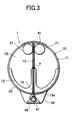
- FIG. 3 is a cross-sectional view taken along line I—I in FIG. 1;
- FIG. 4A is a vertical cross-sectional view illustrating the coupling between a diaphragm and a suspension chord
- FIG. 4B illustrates the coupling as viewed from the direction indicated by an arrow II in FIG. 4A;
- FIG. 5 is a cross-sectional view taken along line III—III in FIG. 2;
- FIG. 6 is a cross-sectional view taken along line IV—IV in FIG. 2 :
- FIG. 7 A and FIG. 7B each illustrate the inside of a gas envelope of the airship while the airship is still on the ground;
- FIG. 7C illustrates the inside of the gas envelope of the airship while the airship is ascending/descending
- FIG. 7D illustrates the inside of the gas envelope of the airship while the airship is keeping a station in the stratosphere
- FIG. 8 is a cross-sectional view illustrating the action of the load weight
- FIG. 9 is a side view schematically illustrating a conventional airship
- FIG. 10 is a cross-sectional view taken along line V—V in FIG. 9;
- FIG. 11 is a cross-sectional view taken along line VI—VI in FIG. 9;
- FIG. 12 is a cross-sectional view taken along line VII—VII in FIG. 9;
- FIG. 13 is a cross-sectional view illustrating the inside of a gas envelope of the airship while the airship is keeping a station in the stratosphere;
- FIG. 14 is a cross-sectional view illustrating the inside of a gas envelope of the airship while the airship is ascending.
- FIG. 15 is a cross-sectional view illustrating the action of the load weight.
- FIG. 1 is a side view illustrating a stratospheric airship 1 .
- FIG. 2 is a cross-sectional view illustrating the stratospheric airship 1 of FIG. 1 taken along the lateral direction.
- FIG. 3 is a cross-sectional view illustrating the stratospheric airship 1 taken along line I—I in FIG. 1 .
- An arrow F denotes the forward direction of the airship 1 .
- the stratospheric airship 1 has a gas envelope 10 which has a generally circular cross section and a generally elliptical shape as viewed in a side view, for example.
- Various instruments and parts are secured to the gas envelope 10 .
- the gas envelope 10 is a generally ellipsoidal balloon defined by a ship hull 11 .
- a solar battery module 41 is attached to the upper surface of the ship hull 11 via an adhesive thermal insulator layer.
- Ballonets 42 and 43 are respectively provided in a front and a rear portion within the ship hull 11 .
- Each of the ballonets 42 and 43 is a small gas envelope filled with air. At low altitudes, air is introduced thereinto so as to maintain the pressure in the gas envelope 10 . As the airship 1 ascends to a higher altitude, air is discharged to accommodate the difference between the atmospheric pressure (which decreases along with an increase in altitude) and the internal pressure of the gas envelope 10 so as to maintain the outer shape of the gas envelope 10 , i.e., the shape of the airship 1 , while the volume of air in the front and rear ballonets 42 and 43 is adjusted to keep the balance of the airship 1 .
- a propulsion unit 45 , a stabilizer 46 , etc., are provided in the rear of the airship 1 .
- a load supporting member 48 is provided under the bottom surface of the ship hull 11 for carrying a load 47 including equipment, a storage battery, a fuel cell, mission payload equipment, etc.
- the gas envelope 10 is vertically divided by a diaphragm 12 , which is a flexible diaphragm, into a buoyant gas compartment 20 containing a buoyant gas and an air compartment 30 containing air.
- the diaphragm 12 is air-tightly coupled along its entire periphery to the ship hull 11 generally at the midpoint along the vertical dimension of the gas envelope 10 .
- An intermediate portion of the diaphragm 12 is coupled to diaphragm supporting members so that the diaphragm 12 is supported generally at the midpoint along the vertical dimension of the gas envelope 10 .
- the diaphragm supporting members are provided as a plurality of suspension chords 13 which extend generally in the vertical direction of the gas envelope 10 passing through the center line “a” (the center line “a” generally corresponds to the central axis of the gas envelope 10 ) which runs along the horizontal direction of the gas envelope 10 .
- the suspension chords 13 are provided to be parallel to one another and perpendicular to the center line “a”, and to connect a center portion of the upper surface of the ship hull 11 and a center portion of the bottom surface of the ship hull 11 .
- the suspension chords 13 are coupled to the diaphragm 12 generally at their longitudinal midpoints.
- FIG. 4A is a vertical cross-sectional view illustrating the coupling between the diaphragm 12 and the suspension chord 13 .
- FIG. 4B illustrates the coupling as viewed from the direction indicated by an arrow II in FIG. 4A.
- a tubular sealing 15 which is made of a soft rubber, or the like, is fitted around the suspension chord 13 , and the diaphragm 12 and the suspension chord 13 are coupled to each other by a retainer ring 16 while ensuring the air-tightness between the buoyant gas compartment 20 and the air compartment 30 .
- the retainer ring 16 includes a central tubular coupling 16 a which is fitted around the sealing member 15 , and a pair of grommets 16 b for vertically sandwiching a peripheral portion of a through hole 12 a provided in the diaphragm 12 .
- the shape of the diaphragm 12 unfolded is close to the shape of the upper or lower half of the ship hull 11 .
- the shape of the diaphragm 12 is slightly smaller than the upper or lower half of the ship hull 11 so as to avoid an interference with the ballonets 42 and 43 provided in the air compartment 30 or a thin film buoyant gas tank 21 provided in an upper portion of the buoyant gas compartment 20 .
- the thin film buoyant gas tank 21 is designed to have a volume equal to about ⁇ fraction (1/14) ⁇ of the total volume of the gas envelope 10 , i.e., the total value of the volume of the buoyant gas in the buoyant gas compartment 20 and the thin film buoyant gas tank 21 and the volume of air in the air compartment 30 .
- the load supporting member 48 (which is provided under the bottom surface of the gas envelope 10 for carrying the load 47 including equipment, a storage battery, a fuel cell, mission payload equipment, etc.) is suspended at its upper end from a lower end 13 a of the suspension chord 13 which is coupled to a center portion of the bottom surface of the ship hull 11 .
- the load supporting member 48 , the load 47 , etc., are enclosed in a thin film fairing 49 .
- the thin film fairing 49 is coupled along its periphery to the bottom surface of the ship hull 11 , and the thin film fairing 49 also provides a function of layering the stream. The tension of the thin film fairing 49 restricts the sloshing of the load supporting member 48 .
- Power cables 14 are provided coaxially with or in parallel to the suspension chords 13 for connecting the solar battery module 41 to the load 47 , e.g., the storage battery, carried by the load supporting member 48 .
- the power cables 14 are provided coaxially with the suspension chords 13 .
- FIG. 5 is a cross-sectional view taken along line III—III in FIG. 2 .
- a buoyant gas inlet 23 is provided in an upper portion of the ship hull 11 for introducing a buoyant gas into the thin film buoyant gas tank 21 .
- the buoyant gas inlet 23 is provided with a valve (not shown).
- the thin film buoyant gas tank 21 is provided with a buoyant gas vent valve 24 for discharging the buoyant gas into the buoyant gas compartment 20 .
- FIG. 6 is a cross-sectional view taken along line IV—IV in FIG. 2 .
- an air blower 31 for introducing the atmosphere into the air compartment 30 so as to pressurize the air compartment 30 and an air vent valve 32 for discharging the air from the air compartment 30 are provided in a bottom portion of the ship hull 11 .
- FIG. 7A to FIG. 7 D and FIG. 8 illustrating the inside of the gas envelope 10 of the stratospheric airship 1 in operation.
- FIG. 7A to FIG. 7D each illustrate the inside of the gas envelope 10 of the airship 1 in operation.
- FIG. 7 A and FIG. 7B each illustrate the inside of the gas envelope 10 of the airship 1 while the airship 1 is still on the ground
- FIG. 7C illustrates the inside of the gas envelope 10 of the airship 1 while the airship 1 is ascending or descending
- FIG. 7D illustrates the inside of the gas envelope 10 of the airship 1 while the airship 1 is keeping a station in the stratosphere.
- FIG. 7 A and FIG. 7C is a cross-sectional view taken along line III—III in FIG. 2
- each of FIG. 7 B and FIG. 7D is a cross-sectional view taken along line IV—IV in FIG. 2 .
- a buoyant gas e.g., a helium gas
- a buoyant gas inlet 23 into the thin film buoyant gas tank 21
- the buoyant gas is further supplied from the thin film buoyant gas tank 21 into the buoyant gas compartment 20 via the buoyant gas vent valve 24 .
- the valve of the buoyant gas inlet 23 and the air vent valve 32 are closed, and the atmosphere is introduced via the air blower 31 into the air compartment 30 so as to pressurize the air compartment 30 to a pressure which is about 500 to 1000 Pa higher than the ambient pressure, thereby maintaining the shape of the a gas envelope 10 .
- the diaphragm 12 is pushed up by the pressurized air in the air compartment 30 , thereby pressurizing the buoyant gas in the buoyant gas compartment 20 and the thin film buoyant gas tank 21 to a pressure in equilibrium with the pressure of the air in the air compartment 30 , e.g., about 500 to 1000 Pa.
- the buoyant gas vent valve 24 which communicates the buoyant gas compartment 20 and the thin film buoyant gas tank 21 with each other is closed to complete the preparation for takeoff.
- the airship 1 starts ascending by an excessive buoyancy which is equal to the buoyancy provided by the buoyant gas in the buoyant gas compartment 20 and the thin film buoyant gas tank 21 minus the total weight of the airship 1 including the equipment.
- the atmospheric pressure gradually decreases.
- the difference between the internal pressure of the gas envelope 10 and the atmospheric pressure gradually increases. This pressure difference creates a tension on the ship hull 11 .
- the air vent valve 32 is opened to discharge the air in the air compartment 30 and reduce the volume of air therein, thereby depressurizing the gas envelope 10 so as to maintain the pressure difference to be less than a predetermined limit pressure difference in view of a safety margin.
- the buoyant gas in the buoyant gas compartment 20 starts expanding according to the difference between the pressure of the buoyant gas in the buoyant gas compartment 20 and the pressure of the air in the air compartment 30 which occurs along with the decrease in the volume of air in the air compartment 30 .
- the pressure of the buoyant gas in the buoyant gas compartment 20 starts decreasing by the expansion of the buoyant gas, thereby beginning to create a pressure difference between the buoyant gas in the buoyant gas compartment 20 and the buoyant gas in the thin film buoyant gas tank 21 .
- This pressure difference creates a tension on the film of the thin film buoyant gas tank 21 .
- the tension may break the film of the thin film buoyant gas tank 21 .
- the buoyant gas vent valve 24 is opened to transfer the buoyant gas in the thin film buoyant gas tank 21 to the buoyant gas compartment 20 in order to prevent the possible break of the film of the thin film buoyant gas tank 21 .
- the buoyant gas transferred into the buoyant gas compartment expands to compensate for the reduction in the volume of air in the gas envelope 10 due to the discharge of air, thereby pushing down the diaphragm 12 as illustrated in FIG. 7 C.
- the volume of the gas envelope 10 is constantly maintained, while the pressure of the gas envelope 10 is reduced to keep the pressure difference between the gas envelope 10 and the atmosphere at or below the limit pressure difference.
- a central portion of the diaphragm 12 is coupled to the plurality of suspension chords 13 successively arranged along the horizontal direction of the airship 1 , whereby the central portion of the diaphragm 12 is substantially fixed to a predetermined position, thereby suppressing the sloshing phenomenon.
- the change in the shape of the diaphragm 12 occurred, such a change would be left-right symmetric or generally left-right symmetric about the central portion of the diaphragm 12 in a well-balanced manner.
- the load supporting member 48 carrying the load 47 (including equipment, a storage battery, a fuel cell, mission payload equipment, etc.), etc., is suspended from the lower end of the suspension chords 13 which are coupled at their upper ends to a central portion of the upper surface of the ship hull 11 , pass through the central portion of the gas envelope 10 , and are coupled at their lower ends to a central portion of the bottom surface of the ship hull 11 .
- the load weight W of the load supporting member 48 and the load 47 directly acts upon the central portion of the upper surface of the ship hull 11 via the suspension chords 13 .
- the load weight W of the load supporting member 48 and the load 47 acts downwardly via the suspension chords 13 upon a central portion of the upper surface of the ship hull 11 (which is the center of the area of the ship hull 11 upon which the buoyancy p of the buoyant gas acts), thereby suppressing the deformation of the buoyant gas compartment 20 due to the buoyancy p.
- the shape of the upper surface of the buoyant gas compartment 20 is maintained, thereby suppressing the asymmetric distribution of the buoyant gas therein, and thus ensuring a good balance of the buoyancy acting upon the gas envelope 10 .
- an arrow P denotes the total of the buoyancy components p.
- the deformation of the shape of the upper surface of the ship hull 11 is suppressed, and thus the shape of the gas envelope 10 is maintained, thereby providing an aerodynamic stability to the airship 1 .
- the power cables 14 connecting the solar battery module 41 to the storage battery, etc., carried by the load supporting member 48 are provided coaxially with or in parallel to the suspension chords 13 which pass through the gas envelope 10 connecting a central portion of the upper surface of the ship hull 11 to a central portion of the lower surface of the ship hull 11 .
- the power cable is provided via the shortest route, thereby shortening the power cables 14 and reducing the possible power loss therealong and the total weight of the airship as compared to the case of the conventional airship where the power cables 14 are provided along the outer surface of the gas envelope.
- the power cables 14 are not exposed on the outside, thereby reducing the air drag.
- the stratospheric airship of the present invention is not limited to the particular embodiment described above, and various modifications may be made thereto without departing from the spirit and scope of the invention.
- a plurality of suspension chords are provided in the embodiment described above, a single suspension chord may be sufficient for a relatively small airship.
- the diaphragm is coupled to the suspension chords generally at the longitudinal midpoints of the suspension chords in the embodiment described above, the suspension chord and the diaphragm may be coupled to each other with the diaphragm coupling point along the suspension chords being shifted up or down depending upon the shape and/or size of the ballonet, the thin film buoyant gas tank, etc.
Landscapes
- Engineering & Computer Science (AREA)
- Mechanical Engineering (AREA)
- Aviation & Aerospace Engineering (AREA)
- Filling Or Discharging Of Gas Storage Vessels (AREA)
- Tents Or Canopies (AREA)
Abstract
Description
Claims (8)
Applications Claiming Priority (3)
| Application Number | Priority Date | Filing Date | Title |
|---|---|---|---|
| DE19846103A DE19846103A1 (en) | 1998-10-07 | 1998-10-07 | vacuum cleaner |
| JP2000-010984 | 2000-01-19 | ||
| JP2000010984A JP3903202B2 (en) | 2000-01-19 | 2000-01-19 | Stratospheric airship |
Publications (2)
| Publication Number | Publication Date |
|---|---|
| US20010002686A1 US20010002686A1 (en) | 2001-06-07 |
| US6427943B2 true US6427943B2 (en) | 2002-08-06 |
Family
ID=26049345
Family Applications (1)
| Application Number | Title | Priority Date | Filing Date |
|---|---|---|---|
| US09/765,764 Expired - Fee Related US6427943B2 (en) | 1998-10-07 | 2001-01-18 | Stratospheric airship |
Country Status (1)
| Country | Link |
|---|---|
| US (1) | US6427943B2 (en) |
Cited By (39)
| Publication number | Priority date | Publication date | Assignee | Title |
|---|---|---|---|---|
| US20030146345A1 (en) * | 2001-05-11 | 2003-08-07 | Daihachi Ogawa | Airship |
| US6609680B2 (en) * | 2000-05-30 | 2003-08-26 | Southwest Research Institute | High altitude airships |
| US6648272B1 (en) * | 2001-06-28 | 2003-11-18 | Keith L. Kothmann | Airship |
| US6811115B2 (en) | 2002-01-15 | 2004-11-02 | Kawasaki Jukogyo Kabushiki Kaisha | Method and system for setting hull parameter of airship and method of adjusting ascension rate of the same |
| US20050156082A1 (en) * | 2004-01-06 | 2005-07-21 | The Boeing Company | Apparatus and method for lighter-than-air aircraft |
| US6966523B2 (en) | 2002-06-25 | 2005-11-22 | 21St Century Airships Inc. | Airship and method of operation |
| US20050258305A1 (en) * | 2002-08-09 | 2005-11-24 | Gili Piers | Dual hull airship controlled by thrust vectoring |
| US20060060695A1 (en) * | 2004-06-21 | 2006-03-23 | Walden Michael K | Mass transfer system for stabilizing an airship and other vehicles subject to pitch and roll moments |
| US20060065777A1 (en) * | 2004-09-27 | 2006-03-30 | Walden Michael K | Systems for actively controlling the aerostatic lift of an airship |
| US20060266886A1 (en) * | 2005-05-24 | 2006-11-30 | Nachbar Daniel W | Hoop stress reduction in a buoyant airship |
| US20070069077A1 (en) * | 2005-09-28 | 2007-03-29 | Colting Hokan S | Airship & method of operation |
| US20070069076A1 (en) * | 2005-09-21 | 2007-03-29 | Heaven George H Jr | Airship having a central fairing to act as a stall strip and to reduce lift |
| US20070075186A1 (en) * | 2005-09-30 | 2007-04-05 | Marimon Thomas L | Airship with lifting gas cell system |
| US20070075184A1 (en) * | 2005-10-05 | 2007-04-05 | Marimon Thomas L | Direct mounted propulsion for non-rigid airships |
| US20080011900A1 (en) * | 2006-07-15 | 2008-01-17 | Javier Quintana | Apparatus and method to control the flight dynamics in a lighter-than-air airship |
| US20080035787A1 (en) * | 2006-08-08 | 2008-02-14 | Thompson Mark N | Lighter-than-air gas handling system and method |
| US20080135678A1 (en) * | 2006-10-23 | 2008-06-12 | Heaven George H | Buoyancy control system for an airship |
| US20080179453A1 (en) * | 2007-01-26 | 2008-07-31 | Thompson Mark N | Modular airship system and method |
| US7424040B2 (en) | 2004-05-07 | 2008-09-09 | Ltas Holdings, Llc | Communication systems and methods for transmitting data in parallel over multiple channels |
| US20110233325A1 (en) * | 2010-03-29 | 2011-09-29 | Dale Clifford Kramer | Cargo Carrying Air Vehicle |
| US8052082B1 (en) | 2006-07-15 | 2011-11-08 | Edward Charles Herlik | Optimized aerodynamic, propulsion, structural and operations features for lighter-than-air vehicles |
| US8091826B2 (en) | 2007-04-24 | 2012-01-10 | Michael Todd Voorhees | Aerostatic buoyancy control system |
| DE102010053372A1 (en) * | 2010-12-03 | 2012-06-06 | Eads Deutschland Gmbh | Altitude Aircraft |
| US20120181381A1 (en) * | 2009-07-28 | 2012-07-19 | Noce S.R.L. | Self-righting aerostat and relative takeoff and recovery system |
| US20120235410A1 (en) * | 2011-03-15 | 2012-09-20 | Serrano Richard J | Lighter than air wind and solar energy conversion system |
| US20140021293A1 (en) * | 2010-07-20 | 2014-01-23 | John Goelet | System and Method for Varying Airship Aerostatic Buoyancy |
| US8720981B1 (en) | 2013-03-12 | 2014-05-13 | Honda Motor Co., Ltd. | Vehicle floor frame stiffener |
| US20140339356A1 (en) * | 2010-03-23 | 2014-11-20 | Athene Works Limited | Aerial vehicle and method of flight |
| US20150360763A1 (en) * | 2012-12-07 | 2015-12-17 | Raven Industries, Inc. | High altitude balloon system |
| WO2016007328A1 (en) * | 2014-07-07 | 2016-01-14 | Adcock Daniel J | Gas envelope propulsion system and related methods |
| US9296460B2 (en) * | 2012-02-14 | 2016-03-29 | Phillip R. Barber | Airship with internal propulsion system |
| US9327817B1 (en) * | 2014-02-03 | 2016-05-03 | Google Inc. | Ballonet for a balloon |
| US9573670B2 (en) * | 2014-02-05 | 2017-02-21 | X Development Llc | Ballonet for a balloon |
| US9802690B2 (en) | 2013-11-04 | 2017-10-31 | Lta Corporation | Cargo airship |
| US9840318B2 (en) | 2007-08-09 | 2017-12-12 | Pierre Balaskovic | Lenticular airship and associated controls |
| US9845141B2 (en) | 2012-12-07 | 2017-12-19 | Raven Industries, Inc. | Atmospheric balloon system |
| US10469021B2 (en) | 2016-10-17 | 2019-11-05 | Aetherix Corporation | Airborne renewable energy generation and storage |
| US20220219800A1 (en) * | 2021-01-11 | 2022-07-14 | Neff Aeronautics, Llc | Rapid air ballast system for an airship |
| US11673347B2 (en) | 2015-02-02 | 2023-06-13 | Aerostar International, Llc | Tendon sleeve for high-altitude balloon and system for making the same |
Families Citing this family (19)
| Publication number | Priority date | Publication date | Assignee | Title |
|---|---|---|---|---|
| EP1599382A2 (en) * | 2003-02-24 | 2005-11-30 | Charles Raymond Luffman | Air vehicle |
| EP1529726A3 (en) * | 2003-11-04 | 2006-09-13 | Daniel Geery | Highly maneuverable powered airship |
| DE10356012A1 (en) * | 2003-11-27 | 2005-06-30 | Airbus Deutschland Gmbh | Arrangement and method for producing water on board an aircraft |
| US7438261B2 (en) | 2004-09-09 | 2008-10-21 | David R. Porter | Stratospheric balloon utilizing electrostatic inflation of walls |
| GB0519849D0 (en) * | 2005-09-29 | 2005-11-09 | Graviless Ltd | Method and device for free-standing support of objects in space |
| AU2006334867A1 (en) * | 2006-01-10 | 2007-07-19 | Kamal Alavi | Unmanned aircraft for telecommunicative or scientific purposes |
| WO2011050138A2 (en) * | 2009-10-23 | 2011-04-28 | Skyacht Aircraft, Inc. | Aerostat envelope construction with zippered sections |
| US9193432B2 (en) | 2010-09-28 | 2015-11-24 | Sakase Adtech Co., Ltd. | Stratospheric stay facility |
| BR112013024635A2 (en) * | 2011-03-31 | 2020-09-01 | Lta Corporation | aircraft including aerodynamic, flotation and implantable structures |
| US8967533B2 (en) * | 2012-08-20 | 2015-03-03 | Google Inc. | Balloon power sources with a buoyancy trade-off |
| CN105000161A (en) * | 2015-07-23 | 2015-10-28 | 北京天航华创科技股份有限公司 | Independently-adjusted solar battery array for stratospheric airship |
| CN105644762B (en) * | 2016-01-19 | 2017-11-28 | 北京航空航天大学 | A kind of new stratospheric airship |
| MX2019004718A (en) * | 2016-10-24 | 2019-09-18 | Sceye Sarl | Airship construction and method where a harness-structure is fastened around a hull. |
| CN110217376B (en) * | 2019-07-23 | 2024-01-30 | 达天飞艇(宁夏)有限公司 | Stratospheric airship and steady-state lifting and cruising method thereof |
| CN110466731B (en) * | 2019-08-24 | 2023-03-17 | 哈尔滨工业大学 | Airship floating weight balance control method based on interaction of air bag and helium bag |
| FR3109139B1 (en) * | 2020-04-09 | 2024-03-01 | Thales Sa | Partial Balloon Stratospheric Ascent System |
| US20210347460A1 (en) * | 2020-05-06 | 2021-11-11 | Aloft Research Corporation | Airship and method of use |
| US20220242547A1 (en) * | 2021-01-29 | 2022-08-04 | Loon Llc | External air bladders |
| CN114348232B (en) * | 2021-12-02 | 2024-03-19 | 北京电子工程总体研究所 | Pressure regulating method for aerostat |
Citations (6)
| Publication number | Priority date | Publication date | Assignee | Title |
|---|---|---|---|---|
| US1682405A (en) * | 1922-04-13 | 1928-08-28 | Firm Luft Fahrzeug Ges M B H | Nonrigid airship |
| US2492800A (en) * | 1948-08-16 | 1949-12-27 | Dewey And Almy Chem Comp | Fast rising sounding balloon |
| US3706433A (en) * | 1970-09-28 | 1972-12-19 | Miles H Sonstegaard | Airship with internal transfer of lifting gas |
| JPS5470597A (en) | 1977-11-11 | 1979-06-06 | Nec Corp | Variable capacity balloon apparatus |
| US4711416A (en) * | 1984-12-06 | 1987-12-08 | Centre National D'etudes Spatiales (C.N.E.S) | Steerable lighter than air balloon |
| US5538203A (en) * | 1994-06-20 | 1996-07-23 | Lockheed Corporation | Ballonet system for a lighter-than-air vehicle |
-
2001
- 2001-01-18 US US09/765,764 patent/US6427943B2/en not_active Expired - Fee Related
Patent Citations (6)
| Publication number | Priority date | Publication date | Assignee | Title |
|---|---|---|---|---|
| US1682405A (en) * | 1922-04-13 | 1928-08-28 | Firm Luft Fahrzeug Ges M B H | Nonrigid airship |
| US2492800A (en) * | 1948-08-16 | 1949-12-27 | Dewey And Almy Chem Comp | Fast rising sounding balloon |
| US3706433A (en) * | 1970-09-28 | 1972-12-19 | Miles H Sonstegaard | Airship with internal transfer of lifting gas |
| JPS5470597A (en) | 1977-11-11 | 1979-06-06 | Nec Corp | Variable capacity balloon apparatus |
| US4711416A (en) * | 1984-12-06 | 1987-12-08 | Centre National D'etudes Spatiales (C.N.E.S) | Steerable lighter than air balloon |
| US5538203A (en) * | 1994-06-20 | 1996-07-23 | Lockheed Corporation | Ballonet system for a lighter-than-air vehicle |
Cited By (70)
| Publication number | Priority date | Publication date | Assignee | Title |
|---|---|---|---|---|
| US6609680B2 (en) * | 2000-05-30 | 2003-08-26 | Southwest Research Institute | High altitude airships |
| US6698686B2 (en) * | 2001-05-11 | 2004-03-02 | Kawasaki Jukogyo Kabushiki Kaisha | Airship |
| US20030146345A1 (en) * | 2001-05-11 | 2003-08-07 | Daihachi Ogawa | Airship |
| US6648272B1 (en) * | 2001-06-28 | 2003-11-18 | Keith L. Kothmann | Airship |
| US6811115B2 (en) | 2002-01-15 | 2004-11-02 | Kawasaki Jukogyo Kabushiki Kaisha | Method and system for setting hull parameter of airship and method of adjusting ascension rate of the same |
| US7055777B2 (en) * | 2002-06-25 | 2006-06-06 | 21St Century Airships Inc. | Airship and method of operation |
| US6966523B2 (en) | 2002-06-25 | 2005-11-22 | 21St Century Airships Inc. | Airship and method of operation |
| US7350746B2 (en) * | 2002-08-09 | 2008-04-01 | Nautilus S.P.A. | Dual hull airship controlled by thrust vectoring |
| US20050258305A1 (en) * | 2002-08-09 | 2005-11-24 | Gili Piers | Dual hull airship controlled by thrust vectoring |
| US20080251635A1 (en) * | 2004-01-06 | 2008-10-16 | Martin Eberle | Apparatus For Lighter-Than-Air Aircraft |
| US7055778B2 (en) * | 2004-01-06 | 2006-06-06 | Martin Eberle | Apparatus and method for lighter-than-air aircraft |
| US20060169836A1 (en) * | 2004-01-06 | 2006-08-03 | The Boeing Company | Apparatus and Method for Lighter-Than-Air Aircraft |
| US7690596B2 (en) | 2004-01-06 | 2010-04-06 | Martin Eberle | Apparatus for lighter-than-air aircraft |
| US7380750B2 (en) | 2004-01-06 | 2008-06-03 | Martin Eberle | Method for lighter-than-air aircraft |
| US20050156082A1 (en) * | 2004-01-06 | 2005-07-21 | The Boeing Company | Apparatus and method for lighter-than-air aircraft |
| US7424040B2 (en) | 2004-05-07 | 2008-09-09 | Ltas Holdings, Llc | Communication systems and methods for transmitting data in parallel over multiple channels |
| US7350749B2 (en) | 2004-06-21 | 2008-04-01 | Ltas Holdings, Llc | Mass transfer system for stabilizing an airship and other vehicles subject to pitch and roll moments |
| US7185848B2 (en) | 2004-06-21 | 2007-03-06 | Ltas Holdings, Llc | Mass transfer system for stabilizing an airship and other vehicles subject to pitch and roll moments |
| US20060060695A1 (en) * | 2004-06-21 | 2006-03-23 | Walden Michael K | Mass transfer system for stabilizing an airship and other vehicles subject to pitch and roll moments |
| US20080164370A1 (en) * | 2004-06-21 | 2008-07-10 | Ltas Holdings Llc | Mass transfer system for stabilizing an airship and other vehicles subject to pitch and roll moments |
| US7878449B2 (en) | 2004-06-21 | 2011-02-01 | Ltas Holdings, Llc | Mass transfer system for stabilizing an airship and other vehicles subject to pitch and roll moments |
| US7156342B2 (en) | 2004-09-27 | 2007-01-02 | Ltas Holdings, Llc | Systems for actively controlling the aerostatic lift of an airship |
| US20060065777A1 (en) * | 2004-09-27 | 2006-03-30 | Walden Michael K | Systems for actively controlling the aerostatic lift of an airship |
| US7669796B2 (en) * | 2005-05-24 | 2010-03-02 | Daniel Nachbar | Hoop stress reduction in a buoyant airship |
| US20060266886A1 (en) * | 2005-05-24 | 2006-11-30 | Nachbar Daniel W | Hoop stress reduction in a buoyant airship |
| US20070069076A1 (en) * | 2005-09-21 | 2007-03-29 | Heaven George H Jr | Airship having a central fairing to act as a stall strip and to reduce lift |
| US7490794B2 (en) | 2005-09-21 | 2009-02-17 | Ltas Holdings, Llc | Airship having a central fairing to act as a stall strip and to reduce lift |
| US20070069077A1 (en) * | 2005-09-28 | 2007-03-29 | Colting Hokan S | Airship & method of operation |
| EP1928730A1 (en) * | 2005-09-28 | 2008-06-11 | 21st Century Airship Technologies Inc. | Improved airship&method of operation |
| US7552893B2 (en) | 2005-09-28 | 2009-06-30 | 21St Century Airship Technologies Inc. | Airship & method of operation |
| EP1928730A4 (en) * | 2005-09-28 | 2011-12-28 | 21St Century Airship Technologies Inc | Improved airship&method of operation |
| WO2007036038A1 (en) * | 2005-09-28 | 2007-04-05 | 21St Century Airship Technologies Inc. | Improved airship & method of operation |
| US7500637B2 (en) * | 2005-09-30 | 2009-03-10 | Lockheed Martin Corporation | Airship with lifting gas cell system |
| US20070075186A1 (en) * | 2005-09-30 | 2007-04-05 | Marimon Thomas L | Airship with lifting gas cell system |
| US7448572B2 (en) * | 2005-10-05 | 2008-11-11 | Lockheed Martin Corporation | Direct mounted propulsion for non-rigid airships |
| US20070075184A1 (en) * | 2005-10-05 | 2007-04-05 | Marimon Thomas L | Direct mounted propulsion for non-rigid airships |
| US20080011900A1 (en) * | 2006-07-15 | 2008-01-17 | Javier Quintana | Apparatus and method to control the flight dynamics in a lighter-than-air airship |
| US8052082B1 (en) | 2006-07-15 | 2011-11-08 | Edward Charles Herlik | Optimized aerodynamic, propulsion, structural and operations features for lighter-than-air vehicles |
| US20080035787A1 (en) * | 2006-08-08 | 2008-02-14 | Thompson Mark N | Lighter-than-air gas handling system and method |
| US7487936B2 (en) | 2006-10-23 | 2009-02-10 | Ltas Holdings, Llc | Buoyancy control system for an airship |
| US20080135678A1 (en) * | 2006-10-23 | 2008-06-12 | Heaven George H | Buoyancy control system for an airship |
| US20080179453A1 (en) * | 2007-01-26 | 2008-07-31 | Thompson Mark N | Modular airship system and method |
| US8091826B2 (en) | 2007-04-24 | 2012-01-10 | Michael Todd Voorhees | Aerostatic buoyancy control system |
| US9840318B2 (en) | 2007-08-09 | 2017-12-12 | Pierre Balaskovic | Lenticular airship and associated controls |
| US9828082B2 (en) | 2007-10-18 | 2017-11-28 | Lta Corporation | Airship having a cargo compartment |
| US20120181381A1 (en) * | 2009-07-28 | 2012-07-19 | Noce S.R.L. | Self-righting aerostat and relative takeoff and recovery system |
| US20140339356A1 (en) * | 2010-03-23 | 2014-11-20 | Athene Works Limited | Aerial vehicle and method of flight |
| US9694894B2 (en) * | 2010-03-23 | 2017-07-04 | Athene Works Limited | Aerial vehicle and method of flight |
| US8544797B2 (en) * | 2010-03-29 | 2013-10-01 | Dale Clifford Kramer | Cargo carrying air vehicle |
| US20110233325A1 (en) * | 2010-03-29 | 2011-09-29 | Dale Clifford Kramer | Cargo Carrying Air Vehicle |
| US20140021293A1 (en) * | 2010-07-20 | 2014-01-23 | John Goelet | System and Method for Varying Airship Aerostatic Buoyancy |
| US8899514B2 (en) * | 2010-07-20 | 2014-12-02 | Lta Corporation | System and method for varying airship aerostatic buoyancy |
| DE102010053372B4 (en) * | 2010-12-03 | 2014-05-28 | Eads Deutschland Gmbh | Altitude Aircraft |
| CN102530231B (en) * | 2010-12-03 | 2016-09-21 | 伊德斯德国股份有限公司 | High-altitude vehicle |
| DE102010053372A1 (en) * | 2010-12-03 | 2012-06-06 | Eads Deutschland Gmbh | Altitude Aircraft |
| CN102530231A (en) * | 2010-12-03 | 2012-07-04 | 伊德斯德国股份有限公司 | High-altitude aerial vehicle |
| US20120235410A1 (en) * | 2011-03-15 | 2012-09-20 | Serrano Richard J | Lighter than air wind and solar energy conversion system |
| US9296460B2 (en) * | 2012-02-14 | 2016-03-29 | Phillip R. Barber | Airship with internal propulsion system |
| US20150360763A1 (en) * | 2012-12-07 | 2015-12-17 | Raven Industries, Inc. | High altitude balloon system |
| US9845141B2 (en) | 2012-12-07 | 2017-12-19 | Raven Industries, Inc. | Atmospheric balloon system |
| US9463861B2 (en) * | 2012-12-07 | 2016-10-11 | Raven Industries, Inc. | High altitude balloon system |
| US8720981B1 (en) | 2013-03-12 | 2014-05-13 | Honda Motor Co., Ltd. | Vehicle floor frame stiffener |
| US9802690B2 (en) | 2013-11-04 | 2017-10-31 | Lta Corporation | Cargo airship |
| US9327817B1 (en) * | 2014-02-03 | 2016-05-03 | Google Inc. | Ballonet for a balloon |
| US9580162B2 (en) * | 2014-02-03 | 2017-02-28 | X Development Llc | Ballonet for a balloon |
| US9573670B2 (en) * | 2014-02-05 | 2017-02-21 | X Development Llc | Ballonet for a balloon |
| WO2016007328A1 (en) * | 2014-07-07 | 2016-01-14 | Adcock Daniel J | Gas envelope propulsion system and related methods |
| US11673347B2 (en) | 2015-02-02 | 2023-06-13 | Aerostar International, Llc | Tendon sleeve for high-altitude balloon and system for making the same |
| US10469021B2 (en) | 2016-10-17 | 2019-11-05 | Aetherix Corporation | Airborne renewable energy generation and storage |
| US20220219800A1 (en) * | 2021-01-11 | 2022-07-14 | Neff Aeronautics, Llc | Rapid air ballast system for an airship |
Also Published As
| Publication number | Publication date |
|---|---|
| US20010002686A1 (en) | 2001-06-07 |
Similar Documents
| Publication | Publication Date | Title |
|---|---|---|
| US6427943B2 (en) | Stratospheric airship | |
| US7552893B2 (en) | Airship & method of operation | |
| US8864063B2 (en) | Tethered airships | |
| US6581873B2 (en) | Hybrid winged airship (dynastat) | |
| US6311925B1 (en) | Airship and method for transporting cargo | |
| US9611025B2 (en) | Additional systems and methods for long endurance airship operations using a free-flying tethered airship system | |
| US9139279B2 (en) | Systems and methods for long endurance airship operations | |
| US5645248A (en) | Lighter than air sphere or spheroid having an aperture and pathway | |
| US4995572A (en) | High altitude multi-stage data acquisition system and method of launching stratospheric altitude air-buoyant vehicles | |
| US7487936B2 (en) | Buoyancy control system for an airship | |
| JP3903202B2 (en) | Stratospheric airship | |
| CN103587674B (en) | The air bag of a kind of dirigible with shape controlling skeleton | |
| JPS62501407A (en) | steerable aerostatic balloon | |
| JP2000280989A (en) | Super-pressure type high altitude airship | |
| US3488019A (en) | Cargo-gas airship with boundary layer control | |
| US20080035787A1 (en) | Lighter-than-air gas handling system and method | |
| US5143322A (en) | Ground handling, altitude control and longitudinal stability of airships | |
| WO2011042316A1 (en) | "momoheli ii" lifting module and vehicles | |
| WO2014088680A2 (en) | Systems and methods for long endurance airship operations | |
| RU2114027C1 (en) | Semirigid controllable aerostatic flying vehicle | |
| RU2141911C1 (en) | Lighter-than air semirigid combined controllable flying vehicle | |
| RU2111146C1 (en) | High-altitude guided aerostatic flying vehicle | |
| WO2019173443A1 (en) | Lighter-than-air leakage reduction | |
| Bock et al. | Lenticular cargo airships: the case for carbon-free fuel operation | |
| JP2002173092A (en) | Airship and method for floating/starting it |
Legal Events
| Date | Code | Title | Description |
|---|---|---|---|
| AS | Assignment |
Owner name: FUJI JUKOGYO KABUSHIKI KAISHA, JAPAN Free format text: INVALID RECORDING;ASSIGNOR:YAMADA, KENICHI;REEL/FRAME:011493/0941 Effective date: 20010116 Owner name: FUJI JUKOGYO KABUSHIKI KAISHI, JAPAN Free format text: ASSIGNMENT OF ASSIGNORS INTEREST;ASSIGNORS:YOKOMAKU, YOSHIO;KOMATSU, KEIJI;SANO, MASAAKI;AND OTHERS;REEL/FRAME:011500/0041 Effective date: 20010116 Owner name: NATIONAL AEROSPACE LABORATORY, JAPAN Free format text: ASSIGNMENT OF ASSIGNORS INTEREST;ASSIGNORS:YOKOMAKU, YOSHIO;KOMATSU, KEIJI;SANO, MASAAKI;AND OTHERS;REEL/FRAME:011500/0041 Effective date: 20010116 |
|
| FEPP | Fee payment procedure |
Free format text: PAYOR NUMBER ASSIGNED (ORIGINAL EVENT CODE: ASPN); ENTITY STATUS OF PATENT OWNER: LARGE ENTITY |
|
| CC | Certificate of correction | ||
| AS | Assignment |
Owner name: JAPAN AEROSPACE EXPLORATION AGENCY, JAPAN Free format text: MERGER CHANGE OF NAME DISSOLUTION OF 1. AND ESTABLISHMENT OF 2;ASSIGNOR:NATIONAL AEROSPACE LABORATORY;REEL/FRAME:015386/0031 Effective date: 20031001 |
|
| FPAY | Fee payment |
Year of fee payment: 4 |
|
| FPAY | Fee payment |
Year of fee payment: 8 |
|
| REMI | Maintenance fee reminder mailed | ||
| LAPS | Lapse for failure to pay maintenance fees | ||
| STCH | Information on status: patent discontinuation |
Free format text: PATENT EXPIRED DUE TO NONPAYMENT OF MAINTENANCE FEES UNDER 37 CFR 1.362 |
|
| FP | Lapsed due to failure to pay maintenance fee |
Effective date: 20140806 |