US6181265B1 - Non-linear digital-to-analog converter - Google Patents
Non-linear digital-to-analog converter Download PDFInfo
- Publication number
- US6181265B1 US6181265B1 US09/285,455 US28545599A US6181265B1 US 6181265 B1 US6181265 B1 US 6181265B1 US 28545599 A US28545599 A US 28545599A US 6181265 B1 US6181265 B1 US 6181265B1
- Authority
- US
- United States
- Prior art keywords
- voltages
- switching portion
- output
- reference voltage
- voltage
- Prior art date
- Legal status (The legal status is an assumption and is not a legal conclusion. Google has not performed a legal analysis and makes no representation as to the accuracy of the status listed.)
- Expired - Lifetime
Links
Images


Classifications
-
- H—ELECTRICITY
- H03—ELECTRONIC CIRCUITRY
- H03M—CODING; DECODING; CODE CONVERSION IN GENERAL
- H03M1/00—Analogue/digital conversion; Digital/analogue conversion
- H03M1/66—Digital/analogue converters
-
- H—ELECTRICITY
- H03—ELECTRONIC CIRCUITRY
- H03M—CODING; DECODING; CODE CONVERSION IN GENERAL
- H03M1/00—Analogue/digital conversion; Digital/analogue conversion
- H03M1/66—Digital/analogue converters
- H03M1/664—Non-linear conversion not otherwise provided for in subgroups of H03M1/66
Definitions
- the present invention relates to a digital-to-analog converter, and more particularly, to a non-linear digital-to-analog converter which realizes non-linear output with overlapped resistor string.
- An analog-to-digital converter is used in the field of instrumentation and control. With the development of microcomputers, parts processed by analog mode have been processed by converting an analog signal to a digital signal using the analog-to-digital converter. For this reason, reliability and efficiency of applied products have improved.
- FIGS. 1 a and 1 b are schematic diagrams illustrating a background art digital-to-analog converter.
- the background art digital-to-analog converter includes a primary resistor string 1 , most significant bit (MSB) switching block 2 , least significant bit (LSB) switching block 3 , a secondary resistor string 4 , and LSB output switching portion 5 .
- Two voltages formed in succession between V 2 and V 1 are applied between M 1 ⁇ M 7 of the primary resistor string 1 using the MSB switching block 2 and the LSB switching block 3 .
- One voltage is output through the LSB output switching portion 5 .
- the background art digital-to-analog converter includes a primary resistor string 6 consisting of Ra 1 ⁇ Ra 2 N/2 ⁇ 1, a first switching block 7 consisting of Sa 1 ⁇ Sa 2 N/2 1, a secondary resistor string 8 consisting of Rb 1 ⁇ Rb 2 N/2 ⁇ 1, a second switching block 9 consisting of Sb 1 ⁇ Sb 2 N/2 ⁇ 1, a cubic resistor string 10 consisting of Rc 1 ⁇ Rc 2 N/2 ⁇ 1, and a third switching block 11 consisting of Sc 1 ⁇ Sc 2 N/2 ⁇ 1.
- resistor ratio of Ra, Rb and Rc is 2 N/2 :2 N/2 :1 and a total of resistor string selected by the MSB plus resistor string selected by the LSB is 2 the number of MSB *2 N/2 of Rc.
- Ra is 2*2 3 times (8 ⁇ 101 (2) ⁇ 1) of Rc in case of 101010 (2) .
- Rb is 5*2 3 times (101 (2) ). Since Rc is always 2 3 , total resistor value is 8*2 3 times (2 3 *2 3 ).
- the secondary resistor string is always fixed at a uniform value, it can be applied to the digital-to-analog converter which outputs linear value. However, it cannot be used in apparatuses which require non-linear value.
- the resistor value may be greater than a desired resistor value due to on-resistor constituting each switching block. This causes incorrect conversion value.
- the present invention is directed to a non-linear digital-to-analog converter that substantially obviates one or more of the problems due to limitations and disadvantages of the related art.
- An object of the present invention is to provide a non-linear digital-to-analog converter which realizes non-linear output with overlapped resistor string.
- a non-linear digital-to-analog converter includes a first reference voltage select switching portion for selectively outputting first and second reference voltages Vh 1 and Vc 1 from externally applied reference voltages Vref[1, . . . 2 N/2 ] and third and fourth reference voltages Vh 2 and Vc 2 from externally applied reference voltages Vref[0, . . . 2 N/2 ⁇ 1] if N bit digital value is input, a resistor string block for outputting Vh[0, . . . 2 N/2 ⁇ 1] number of level voltages, Vc[0, . . .
- FIGS. 1 a and 1 b are schematic views illustrating a background art digital-to-analog converter
- FIG. 2 is a block diagram illustrating a non-linear digital-to-analog converter according to the present invention
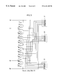
- FIG. 3 is a detailed schematic view illustrating a first reference voltage first select switching portion of a non-linear digital-to-analog converter according to the present invention
- FIG. 4 is a detailed schematic view illustrating a first reference voltage second select switching portion of a non-linear digital-to-analog converter according to the present invention
- FIG. 5 is a detailed schematic view illustrating a resistor string block of a non-linear digital-to-analog converter according to the present invention
- FIG. 6 is a detailed schematic view illustrating a second reference voltage first select switching portion of a non-linear digital-to-analog converter according to the present invention
- FIG. 7 is a detailed schematic view illustrating a second reference voltage second select switching portion of a non-linear digital-to-analog converter according to the present invention.
- FIG. 8 is a detailed schematic view illustrating a second reference voltage third select switching portion of a non-linear digital-to-analog converter according to the present invention.
- FIG. 9 is a detailed schematic view illustrating an output switching portion of a non-linear digital-to-analog converter according to the present invention.
- FIG. 2 is a block diagram illustrating a non-linear digital-to-analog converter according to the present invention.
- a digital-to-analog converter of the present invention is intended that non-linear output is available with a small number of resistors.
- the non-linear digital-to-analog converter includes a first reference voltage first select switching portion 21 for outputting reference voltages Vh 1 and Vc 1 from externally applied reference voltages Vref1, . . . 2 N/2 ] for analog conversion of N bit digital value and MSBb[0, . . . 2 N/2 ⁇ 1] signal, a first reference voltage second select switching portion 22 for outputting reference voltages Vh 2 and Vc 2 from externally applied reference voltages Vref[0, . . . 2 N/2 ⁇ 1] and MSB[0, . . . 2 N/2 ⁇ 1] signal, a resistor string block 23 for outputting Vh[0, . . .
- a second reference voltage first select switching portion 24 for outputting a first analog conversion voltage V 1 from the Vh[0, . . . 2 N/2 ⁇ 1] number of level voltages and LSBb[0, . . . 2 N/2 ⁇ 1]
- a second reference voltage second select switching portion 25 for outputting a second analog conversion voltage V 2 from the Vc[0, . .
- a second reference voltage third select switching portion 26 for outputting a third analog conversion voltage V 3 from the V 1 [0, . . . 2 N/2 ⁇ 1] number of level voltages and LSB[0, . . .
- the first reference voltage first select switching portion 21 includes first, second, third, fourth, fifth, sixth, seventh and eighth PMOS transistors 31 , 32 , 33 , 34 , 35 , 36 , 37 and 38 turned on depending on which one of input signals MSBb[0, . . . , 2 N/2 ⁇ 1], i.e., any one of input data / 111 , / 110 , / 101 , / 100 , / 011 , / 010 , / 001 , / 000 is input, for respectively switching reference voltages of Vref[1, . . . , 2 N/2 ], i.e., Vref 8 , Vref 7 , Vref 6 , Vref 5 , Vref 4 , Vref 3 , Vref 2 , Vref 1 of different levels.
- one of the reference voltages Vref 8 and Vref 1 respectively output from the first PMOS transistor 31 and the eighth PMOS transistor 38 which are respectively turned on by the input data / 111 and / 000 is output as a conversion voltage Vh 1 corresponding to high bit.
- any one of the reference voltages Vref 7 , Vref 6 , Vref 5 , Vref 4 , Vref 3 and Vref 2 output from the second to seventh PMOS transistors 32 , 33 , 34 , 35 , 36 and 37 which are turned on by the input data / 110 , / 101 , / 100 , / 011 , / 010 and / 001 is output as a conversion voltage Vc 1 corresponding to high common bit.
- the first reference voltage second select switching portion 22 includes first, second, third, fourth, fifth, sixth, seventh and eighth NMOS transistors 41 , 42 , 43 , 44 , 45 , 46 , 47 and 48 turned on depending on which one of input signals MSB[0, . . . , 2 N/2 ⁇ 1], i.e., any one of input data 111 , 110 , 101 , 100 , 011 , 010 , 001 , 000 is input, for respectively switching reference voltages of Vref[1, . . .
- one of the reference voltages Vref 7 and Vref 1 respectively output from the first NMOS transistor 41 and the eighth NMOS transistor 48 which are turned on by the input data 111 and 000 , respectively, is output as a conversion voltage Vh 2 corresponding to high bit.
- any one of the reference voltages Vref 6 , Vref 5 , Vref 4 , Vref 3 , Vref 2 and Vref 1 output from the second, third, fourth, fifth, sixth and seventh NMOS transistors 42 , 43 , 44 , 45 , 46 and 47 which are turned on by the input data 110 , 101 , 100 , 011 , 010 and 001 is output as a conversion voltage Vc 2 corresponding to high common bit.
- the resistor string block of the non-linear digital-to-analog converter will be described in detail with reference to FIG. 5 .
- Vh 1 of the voltages Vh 1 , Vc 1 , Vh 2 and Vc 2 output from the first reference voltage first select switching portion 21 and the first reference voltage second select switching portion 22 and its counterpart voltage Vh 2 are input to the resistor string block 23 .
- Vc 1 and its counterpart voltage Vc 2 are input to the resistor string block 23 .
- the resistor string block 23 includes a plurality of resistors R 1 ⁇ R 20 connected in series, a first reference voltage first output terminal 51 , a first reference voltage second output terminal 52 , and a first reference voltage third output terminal 53 .
- Output lines are formed between each of the resistors R 1 ⁇ R 20 to divide input voltage into 2 N/2 .
- the output lines consist of Vh[0, . . . , 2 N/2 ⁇ 1], Vc[0, . . . , 2 N/2 ⁇ 1], and V 1 [0, . . . , 2 N/2 ⁇ 1].
- Each output line of the first reference voltage first output terminal 51 consisting of Vh[0, . . . , 2 N/2 ⁇ 1] number of output lines will be described below.
- the output line of Vh ⁇ 7> is directly connected to the output line Vh 1 of the first reference voltage first select switching portion 21 not through the resistor.
- the output line of Vh ⁇ 6> is connected between the resistor R 6 and the resistor R 7 .
- the output line of Vh ⁇ 5> is connected between the resistor R 10 and the resistor R 11
- the output line of Vh ⁇ 4> is connected between the resistor R 12 and the resistor R 13
- the output line of Vh ⁇ 3> is connected between the resistor R 14 and the resistor R 15
- the output line of Vh ⁇ 2> is connected between the resistor R 16 and the resistor R 17
- the output line of Vh ⁇ 1> is connected between the resistor R 18 and the resistor R 19 .
- the output line of Vh ⁇ 0> is directly connected to the output line Vh 2 of the first reference voltage second select switching portion 22 not through the resistor.
- Each output line of the first reference voltage second output terminal 52 consisting of Vc[0, . . . 2 N/2 ⁇ 1] number of output lines will be described below.
- the output line of Vc ⁇ 7> is directly connected to the output line Vc 1 of the first reference voltage first select switching portion 21 not through the resistor.
- the output line of Vc ⁇ 6> is connected between the resistor R 5 and the resistor R 6 .
- the output line of Vc ⁇ 5> is connected between the resistor R 7 and the resistor R 8
- the output line of Vc ⁇ 4> is connected between the resistor R 9 and the resistor R 10
- the output line of Vc ⁇ 3> is connected between the resistor R 11 and the resistor R 12
- the output line of Vc ⁇ 2> is connected between the resistor R 13 and the resistor R 14
- the output line of Vc ⁇ 1> is connected between the resistor R 15 and the resistor R 16 .
- the output line of Vc ⁇ 0> is directly connected to the output line Vc 2 of the first reference voltage second select switching portion 22 not through the resistor.
- Each output line of the first reference voltage third output terminal 53 consisting of V 1 [0, .. . , 2 N/2 ⁇ 1] number of output lines will be described below.
- the output line of V 1 ⁇ 7> is directly connected to the output line Vh 1 of the first reference voltage first select switching portion 21 not through the resistor.
- the output line of V 1 ⁇ 6> is connected between the resistor R 2 and the resistor R 3 .
- the output line of V 1 ⁇ 5> is connected between the resistor R 4 and the resistor RS
- the output line of V 1 ⁇ 4> is connected between the resistor R 6 and the resistor R 7
- the output line of V 1 ⁇ 3> is connected between the resistor R 8 and the resistor R 9
- the output line of V 1 ⁇ 2> is connected between the resistor R 10 and the resistor R 11
- the output line of V 1 ⁇ 1> is connected between the resistor R 14 and the resistor R 15 .
- the output line of V 1 ⁇ 0> is directly connected to the output line Vh 2 of the first reference voltage second select switching portion 22 not through the resistor.
- the second reference voltage first, second and third select switching portions will be described in detail with reference to FIGS. 6 to 8 .
- the second reference voltage first select switching portion 24 includes first, second, third, fourth, fifth, sixth, seventh and eighth PMOS transistors 61 , 62 , 63 , 64 , 65 , 66 , 67 and 68 turned on depending on which one of input signals LSBb[0, . . . , 2 N/2 ⁇ 1], i.e., any one of low bit data / 111 , / 110 , / 101 , / 100 , / 011 , / 010 , / 001 , / 000 is input, for respectively selecting any one of output values Vh[0, . . . , 2 N/2 ⁇ 1] output from the resistor string block 23 and outputting it as a first analog conversion voltage V 1 .
- the second reference voltage second select switching portion 25 includes first to eighth transmission gates 71 , 72 , 73 , 74 , 75 , 76 , 77 and 78 turned on depending on which data of input signals LSBb[0, . . . , 2 N/2 ⁇ 1], i.e., any one of low bit data / 111 , / 110 , / 101 , / 100 , / 011 , / 010 , / 001 , / 000 and their counterpart data LSB[0, . . .
- the second reference voltage third select switching portion 26 includes first to eighth NMOS transistors 61 , 62 , 63 , 64 , 65 , 66 , 67 and 68 turned on depending on which data of input signals LSB[0, . . . , 2 N/2 ⁇ 1], i.e., any one of low bit data 111 , 110 , 101 , 100 , 011 , 010 , 001 , 000 is input, for respectively selecting any one of output values V 1 [0, . . . , 2 N/2 ⁇ 1] output from the resistor string block 23 and outputting it as a third analog conversion voltage V 3 .
- the output switching portion includes a PMOS transistor 91 selectively turned on/off by MSBb ⁇ 2 N/2 ⁇ 1> applied to the gate, for selectively outputting the first analog conversion voltage V 1 , a first transmission gate 92 selectively turned on/off by MSBb ⁇ 2 N/2 ⁇ 1> applied to the gate of the PMOS transistor and MSB ⁇ 2 N/2 ⁇ 1> applied to the gate of the NMOS transistor, for selectively outputting the second analog conversion voltage V 2 , a second transmission gate 93 connected to an output terminal of the first transmission gate 92 , for selectively outputting an output signal of the first transmission gate 92 by MSBb ⁇ 0> applied to the gate of the PMOS transistor and MSB ⁇ 0> applied to the gate of the NMOS transistor, and an NMOS transistor 94 turned on/off by MSB ⁇ 0> applied to the gate, for selectively outputting the third analog conversion voltage V 3 .
- Vh 1 or Vc 1 is selected from the Vref[1, . . . , 2 N/2 ⁇ 1] input by MSBb[0, . . . , 2 N/2 ⁇ 1] signals and output through the first reference voltage first select switching portion 21 .
- Vh 2 or Vc 2 is selected from the Vref[0, . . . , 2 N/2 ⁇ 1] input by MSB[0, . . . , 2 N/2 ⁇ 1] signals and output through the first reference voltage second select switching portion 22 .
- Vh 1 is selected and output from the first reference voltage first select switching portion 21
- Vh 2 is selected and output from the first reference voltage first select switching portion 22 .
- Vc 1 is selected and output from the first reference voltage first select switching portion 21
- Vc 2 is selected and output from the first reference voltage second select switching portion 22 .
- the selected first reference voltages Vh 1 and Vh 2 or Vc 1 and Vh 2 are divided into 2 N/2 by the resistor string block 23 . Since the first reference voltages are all overlapped, Vh[0, . . . , 2 N/2 ⁇ 1] level voltages, Vc[0, . . . , 2 N/2 ⁇ 1] level voltages, and V 1 [0, . . . , 2 N/2 ⁇ 1] level voltages are all output from the resistor string block 23 . However, one voltage is actually used for analog conversion. For example, if Vh 1 and Vh 2 are applied, the Vh[0, . . .
- Vc[0, . . . , 2 N/2 ⁇ 1] and V 1 [0, . . . , 2 N/2 ⁇ 1] have the output values which are not used for analog conversion.
- Vh[0, . . . , 2 N/2 ⁇ 1], Vc[0, . . . , 2 N/2 ⁇ 1] and V 1 [0, . . . , 2 N/2 ⁇ 1] output from the resistor string block 23 are respectively output as the first, second and third analog conversion voltages V 1 , V 2 and V 3 by the second reference voltage first, second and third select switching portions 24 , 25 and 26 .
- one of the Vh[0, . . . , 2 N/2 ⁇ 1] voltage values output from the resistor string block 23 is selected through the second reference voltage first select switching portion 24 by the LSBb[0, . . . , 2 N/2 ⁇ 1] and output as the first analog conversion voltage V 1 .
- one of the Vc[0, . . . , 2 N/2 ⁇ 1] voltage values output from the resistor string block 23 is selected through the second reference voltage second select switching portion 25 by the LSBb[0, . . . , 2 N/2 ⁇ 1] and LSB[0, . . . , 2 N/2 ⁇ 1] and output as the second analog conversion voltage V 2 .
- one of the V 1 [0, . . . , 2 N/2 ⁇ 1] voltage values output from the resistor string block 23 is selected through the second reference voltage third select switching portion 26 by the LSBE[0, . . . , 2 N/2 ⁇ 1] and output as the third analog conversion voltage V 3 .
- One of the first, second and third analog conversion values V 1 , V 2 and V 3 is output as a desired output value.
- one of the first, second and third analog conversion voltages V 1 , V 2 and V 3 are selectively output as an analog conversion value through the output switching portion 27 by combination of MSBb ⁇ 0>, MSBb ⁇ 2 N/2 ⁇ 1>, MSB ⁇ 0>, and MSB ⁇ 2 N/2 ⁇ 1>.
- the output condition of the analog conversion value from the output switching portion 27 is as follows.
- Vh ⁇ 0>:Vh ⁇ 1>: Vh ⁇ 2>:Vh ⁇ 3>:Vh ⁇ 4>:Vh ⁇ 5>:Vh ⁇ 6>:Vh ⁇ 7> 7:4:1:1:1: 1:1:1.
- the output voltage ratio of the resistor sting is adjusted by the number of the resistors.
- the present invention provides a digital-to-analog converter having non-linear output value at a small number of the resistors.
- various linear outputs can be achieved by adjusting the number of the resistors.
- the non-linear digital-to-analog converter of the present invention has the following advantages.
- the size of the converter can be reduced.
- the output voltage ratio is adjusted by the number of the resistors constituting the resistor string, the non-linear digital-to-analog converter having correct conversion value can be provided.
Landscapes
- Engineering & Computer Science (AREA)
- Theoretical Computer Science (AREA)
- Physics & Mathematics (AREA)
- Nonlinear Science (AREA)
- Analogue/Digital Conversion (AREA)
Abstract
Description
Claims (7)
Applications Claiming Priority (2)
| Application Number | Priority Date | Filing Date | Title |
|---|---|---|---|
| KR98/33511 | 1998-08-18 | ||
| KR1019980033511A KR100282447B1 (en) | 1998-08-18 | 1998-08-18 | Nonlinear Digital / Analog Converter |
Publications (1)
| Publication Number | Publication Date |
|---|---|
| US6181265B1 true US6181265B1 (en) | 2001-01-30 |
Family
ID=19547572
Family Applications (1)
| Application Number | Title | Priority Date | Filing Date |
|---|---|---|---|
| US09/285,455 Expired - Lifetime US6181265B1 (en) | 1998-08-18 | 1999-04-02 | Non-linear digital-to-analog converter |
Country Status (2)
| Country | Link |
|---|---|
| US (1) | US6181265B1 (en) |
| KR (1) | KR100282447B1 (en) |
Cited By (11)
| Publication number | Priority date | Publication date | Assignee | Title |
|---|---|---|---|---|
| US6437721B1 (en) * | 1999-09-24 | 2002-08-20 | Kabushiki Kaisha Toshiba | Semiconductor integrated circuit apparatus for performing DA/AD conversion with high accuracy using a potential distribution of a string resistor |
| US20030227404A1 (en) * | 2001-02-22 | 2003-12-11 | Leopold Kostal Gmbh & Co. | Electric switch |
| US20040233088A1 (en) * | 2003-05-22 | 2004-11-25 | Ess Technology, Inc. | Digital to analog converter having a low power semi-analog finite impulse response circuit |
| US20050128112A1 (en) * | 2003-12-11 | 2005-06-16 | Semiconductor Energy Laboratory Co., Ltd. | D/A converter for a digital signal after non-linear A/D conversion, audio signal processing circuit and liquid crystal display device including the same |
| US20060284752A1 (en) * | 2005-06-21 | 2006-12-21 | Kim Byung H | Digital/analog converter |
| US20070090983A1 (en) * | 2005-10-24 | 2007-04-26 | Chih-Jen Yen | Apparatus for driving display panel and digital-to-analog converter thereof |
| WO2008026067A2 (en) * | 2006-08-31 | 2008-03-06 | Ati Technologies Ulc | Reduced component digital to analog decoder and method |
| US7532142B1 (en) * | 2008-06-13 | 2009-05-12 | International Business Machines Corporation | Structures for systems and methods of generating an analog signal |
| US20090160691A1 (en) * | 2007-12-21 | 2009-06-25 | International Business Machines Corporation | Digital to Analog Converter Having Fastpaths |
| US20090160689A1 (en) * | 2007-12-21 | 2009-06-25 | International Business Machines Corporation | High speed resistor-based digital-to-analog converter (dac) architecture |
| US20110102226A1 (en) * | 2009-10-30 | 2011-05-05 | Analog Devices, Inc. | Digital-to-analogue converter |
Citations (5)
| Publication number | Priority date | Publication date | Assignee | Title |
|---|---|---|---|---|
| US4918448A (en) | 1987-10-09 | 1990-04-17 | International Business Machines Corporation | Device for extending the resolution of a N-bit resistive digital-to-analog converter to a (N+P)-bit digital-to-analog converter |
| US5059978A (en) * | 1990-12-20 | 1991-10-22 | Vlsi Technology, Inc. | Resistor-string digital to analog converters with auxiliary coarse ladders |
| US5495245A (en) | 1994-04-26 | 1996-02-27 | Analog Devices, Inc. | Digital-to-analog converter with segmented resistor string |
| US5648780A (en) * | 1994-05-03 | 1997-07-15 | Unitrode Corporation | Digital to analog converter |
| US5999115A (en) * | 1998-04-20 | 1999-12-07 | Motorola, Inc. | Segmented DAC using PMOS and NMOS switches for improved span |
-
1998
- 1998-08-18 KR KR1019980033511A patent/KR100282447B1/en not_active IP Right Cessation
-
1999
- 1999-04-02 US US09/285,455 patent/US6181265B1/en not_active Expired - Lifetime
Patent Citations (5)
| Publication number | Priority date | Publication date | Assignee | Title |
|---|---|---|---|---|
| US4918448A (en) | 1987-10-09 | 1990-04-17 | International Business Machines Corporation | Device for extending the resolution of a N-bit resistive digital-to-analog converter to a (N+P)-bit digital-to-analog converter |
| US5059978A (en) * | 1990-12-20 | 1991-10-22 | Vlsi Technology, Inc. | Resistor-string digital to analog converters with auxiliary coarse ladders |
| US5495245A (en) | 1994-04-26 | 1996-02-27 | Analog Devices, Inc. | Digital-to-analog converter with segmented resistor string |
| US5648780A (en) * | 1994-05-03 | 1997-07-15 | Unitrode Corporation | Digital to analog converter |
| US5999115A (en) * | 1998-04-20 | 1999-12-07 | Motorola, Inc. | Segmented DAC using PMOS and NMOS switches for improved span |
Cited By (22)
| Publication number | Priority date | Publication date | Assignee | Title |
|---|---|---|---|---|
| US6437721B1 (en) * | 1999-09-24 | 2002-08-20 | Kabushiki Kaisha Toshiba | Semiconductor integrated circuit apparatus for performing DA/AD conversion with high accuracy using a potential distribution of a string resistor |
| US20030227404A1 (en) * | 2001-02-22 | 2003-12-11 | Leopold Kostal Gmbh & Co. | Electric switch |
| US6747544B2 (en) * | 2001-02-22 | 2004-06-08 | Leopold Kostal Gmbh & Co. Kg | Electric switch |
| US20040233088A1 (en) * | 2003-05-22 | 2004-11-25 | Ess Technology, Inc. | Digital to analog converter having a low power semi-analog finite impulse response circuit |
| US6844838B2 (en) * | 2003-05-22 | 2005-01-18 | Ess Technology, Inc. | Digital to analog converter having a low power semi-analog finite impulse response circuit |
| US7369074B2 (en) * | 2003-12-11 | 2008-05-06 | Semiconductor Energy Laboratory Co., Ltd. | D/A converter for a digital signal after non-linear A/D conversion, audio signal processing circuit and liquid crystal display device including the same |
| US20050128112A1 (en) * | 2003-12-11 | 2005-06-16 | Semiconductor Energy Laboratory Co., Ltd. | D/A converter for a digital signal after non-linear A/D conversion, audio signal processing circuit and liquid crystal display device including the same |
| US7375669B2 (en) * | 2005-06-21 | 2008-05-20 | Samsung Electro-Mechanics Co., Ltd. | Digital/analog converter |
| US20060284752A1 (en) * | 2005-06-21 | 2006-12-21 | Kim Byung H | Digital/analog converter |
| US20070090983A1 (en) * | 2005-10-24 | 2007-04-26 | Chih-Jen Yen | Apparatus for driving display panel and digital-to-analog converter thereof |
| US7221304B2 (en) * | 2005-10-24 | 2007-05-22 | Novatek Microelectronics Corp. | Apparatus for driving display panel and digital-to-analog converter thereof |
| US20100013689A1 (en) * | 2006-08-31 | 2010-01-21 | Ati Technologies Ulc | Reduced component digital to analog decoder and method |
| WO2008026067A2 (en) * | 2006-08-31 | 2008-03-06 | Ati Technologies Ulc | Reduced component digital to analog decoder and method |
| WO2008026067A3 (en) * | 2006-08-31 | 2008-05-22 | Ati Technologies Ulc | Reduced component digital to analog decoder and method |
| US8031093B2 (en) | 2006-08-31 | 2011-10-04 | Ati Technologies Ulc | Reduced component digital to analog decoder and method |
| US20090160691A1 (en) * | 2007-12-21 | 2009-06-25 | International Business Machines Corporation | Digital to Analog Converter Having Fastpaths |
| US20090160689A1 (en) * | 2007-12-21 | 2009-06-25 | International Business Machines Corporation | High speed resistor-based digital-to-analog converter (dac) architecture |
| US7710302B2 (en) * | 2007-12-21 | 2010-05-04 | International Business Machines Corporation | Design structures and systems involving digital to analog converters |
| US7868809B2 (en) | 2007-12-21 | 2011-01-11 | International Business Machines Corporation | Digital to analog converter having fastpaths |
| US7532142B1 (en) * | 2008-06-13 | 2009-05-12 | International Business Machines Corporation | Structures for systems and methods of generating an analog signal |
| US20110102226A1 (en) * | 2009-10-30 | 2011-05-05 | Analog Devices, Inc. | Digital-to-analogue converter |
| US7956786B2 (en) * | 2009-10-30 | 2011-06-07 | Analog Devices, Inc. | Digital-to-analogue converter |
Also Published As
| Publication number | Publication date |
|---|---|
| KR100282447B1 (en) | 2001-02-15 |
| KR20000014223A (en) | 2000-03-06 |
Similar Documents
| Publication | Publication Date | Title |
|---|---|---|
| US6914547B1 (en) | Triple resistor string DAC architecture | |
| KR100186679B1 (en) | Digital-to-analog converter | |
| US5495245A (en) | Digital-to-analog converter with segmented resistor string | |
| US5969657A (en) | Digital to analog converter | |
| US5243347A (en) | Monotonic current/resistor digital-to-analog converter and method of operation | |
| KR900008821B1 (en) | Digital to analog converter | |
| US5259002A (en) | Communication link | |
| US7443201B2 (en) | Low voltage differential signaling receiver with a digital resistor unit and low voltage differential signaling interface system having the same | |
| US6181265B1 (en) | Non-linear digital-to-analog converter | |
| US6567026B1 (en) | Voltage scaling digital-to- analog converter with impedance strings | |
| EP0378840A2 (en) | Digital to analog converter having single resistive string with shiftable voltage thereacross | |
| US5943000A (en) | Compensated MOS string and DAC employing such a potentiometric string | |
| US5043731A (en) | Digital-to-analog converter having a ladder type resistor network | |
| EP0466145B1 (en) | D/A converter | |
| US5230054A (en) | Priority order judging device | |
| US6339391B1 (en) | Method and apparatus for optimizing crossover voltage for differential pair switches in a current-steering digital-to-analog converter or the like | |
| US6999016B2 (en) | D/A converter and semiconductor device | |
| US4803461A (en) | R-2R type D/A converter circuit | |
| US7277036B2 (en) | Digital-to-analog converting circuit | |
| US5220306A (en) | Digital signal comparator for comparing n-bit binary signals | |
| US4641131A (en) | Circuit arrangement for converting a digital input signal into an analog output signal | |
| EP0660529B1 (en) | Digital/analog converting circuit | |
| US6218871B1 (en) | Current-switching method and circuit for digital-to-analog converters | |
| US7952384B2 (en) | Data transmitter and related semiconductor device | |
| KR100282443B1 (en) | Digital / Analog Converter |
Legal Events
| Date | Code | Title | Description |
|---|---|---|---|
| AS | Assignment |
Owner name: LG SEMICON CO., LTD., KOREA, REPUBLIC OF Free format text: ASSIGNMENT OF ASSIGNORS INTEREST;ASSIGNOR:LEE, WON KEE;REEL/FRAME:010953/0508 Effective date: 19990305 |
|
| FEPP | Fee payment procedure |
Free format text: PAYOR NUMBER ASSIGNED (ORIGINAL EVENT CODE: ASPN); ENTITY STATUS OF PATENT OWNER: LARGE ENTITY |
|
| STCF | Information on status: patent grant |
Free format text: PATENTED CASE |
|
| CC | Certificate of correction | ||
| FPAY | Fee payment |
Year of fee payment: 4 |
|
| AS | Assignment |
Owner name: HYNIX SEMICONDUCTOR INC., KOREA, REPUBLIC OF Free format text: CHANGE OF NAME;ASSIGNOR:LG SEMICON CO., LTD.;REEL/FRAME:015246/0634 Effective date: 19990726 |
|
| AS | Assignment |
Owner name: MAGNACHIP SEMICONDUCTOR, LTD., KOREA, REPUBLIC OF Free format text: ASSIGNMENT OF ASSIGNORS INTEREST;ASSIGNOR:HYNIX SEMICONDUCTOR, INC.;REEL/FRAME:016216/0649 Effective date: 20041004 |
|
| AS | Assignment |
Owner name: U.S. BANK NATIONAL ASSOCIATION, AS COLLATERAL TRUS Free format text: SECURITY INTEREST;ASSIGNOR:MAGNACHIP SEMICONDUCTOR, LTD.;REEL/FRAME:016470/0530 Effective date: 20041223 |
|
| FPAY | Fee payment |
Year of fee payment: 8 |
|
| FEPP | Fee payment procedure |
Free format text: PAYER NUMBER DE-ASSIGNED (ORIGINAL EVENT CODE: RMPN); ENTITY STATUS OF PATENT OWNER: LARGE ENTITY |
|
| FEPP | Fee payment procedure |
Free format text: PAYOR NUMBER ASSIGNED (ORIGINAL EVENT CODE: ASPN); ENTITY STATUS OF PATENT OWNER: LARGE ENTITY |
|
| AS | Assignment |
Owner name: MAGNACHIP SEMICONDUCTOR LTD.,KOREA, DEMOCRATIC PEO Free format text: RELEASE BY SECURED PARTY;ASSIGNOR:U.S. BANK NATIONAL ASSOCIATION;REEL/FRAME:024563/0807 Effective date: 20100527 |
|
| FPAY | Fee payment |
Year of fee payment: 12 |
|
| AS | Assignment |
Owner name: MAGNACHIP SEMICONDUCTOR LTD., KOREA, REPUBLIC OF Free format text: CORRECTIVE ASSIGNMENT TO CORRECT THE RECEIVING PARTY ADDRESS PREVIOUSLY RECORDED AT REEL: 024563 FRAME: 0807. ASSIGNOR(S) HEREBY CONFIRMS THE RELEASE BY SECURED PARTY;ASSIGNOR:US BANK NATIONAL ASSOCIATION;REEL/FRAME:034469/0001 Effective date: 20100527 |