US6150995A - Combined photovoltaic array and RF reflector - Google Patents
Combined photovoltaic array and RF reflector Download PDFInfo
- Publication number
- US6150995A US6150995A US09/148,130 US14813098A US6150995A US 6150995 A US6150995 A US 6150995A US 14813098 A US14813098 A US 14813098A US 6150995 A US6150995 A US 6150995A
- Authority
- US
- United States
- Prior art keywords
- truss
- solar array
- pliant
- solar
- reflector
- Prior art date
- Legal status (The legal status is an assumption and is not a legal conclusion. Google has not performed a legal analysis and makes no representation as to the accuracy of the status listed.)
- Expired - Fee Related
Links
- 239000000463 material Substances 0.000 claims description 15
- 230000008878 coupling Effects 0.000 claims 2
- 238000010168 coupling process Methods 0.000 claims 2
- 238000005859 coupling reaction Methods 0.000 claims 2
- 238000003491 array Methods 0.000 abstract description 12
- 238000010276 construction Methods 0.000 description 7
- 230000002093 peripheral effect Effects 0.000 description 3
- 229910021417 amorphous silicon Inorganic materials 0.000 description 2
- 239000004744 fabric Substances 0.000 description 2
- 230000010354 integration Effects 0.000 description 2
- 230000005855 radiation Effects 0.000 description 2
- ZOKXTWBITQBERF-UHFFFAOYSA-N Molybdenum Chemical compound [Mo] ZOKXTWBITQBERF-UHFFFAOYSA-N 0.000 description 1
- 238000004891 communication Methods 0.000 description 1
- 230000005611 electricity Effects 0.000 description 1
- 230000008030 elimination Effects 0.000 description 1
- 238000003379 elimination reaction Methods 0.000 description 1
- 238000005516 engineering process Methods 0.000 description 1
- 239000000446 fuel Substances 0.000 description 1
- PCHJSUWPFVWCPO-UHFFFAOYSA-N gold Chemical compound [Au] PCHJSUWPFVWCPO-UHFFFAOYSA-N 0.000 description 1
- 239000010931 gold Substances 0.000 description 1
- 229910052737 gold Inorganic materials 0.000 description 1
- 238000004519 manufacturing process Methods 0.000 description 1
- 230000007246 mechanism Effects 0.000 description 1
- 238000000034 method Methods 0.000 description 1
- 238000012986 modification Methods 0.000 description 1
- 230000004048 modification Effects 0.000 description 1
- 238000007665 sagging Methods 0.000 description 1
- 239000004065 semiconductor Substances 0.000 description 1
Images
Classifications
-
- H—ELECTRICITY
- H01—ELECTRIC ELEMENTS
- H01Q—ANTENNAS, i.e. RADIO AERIALS
- H01Q15/00—Devices for reflection, refraction, diffraction or polarisation of waves radiated from an antenna, e.g. quasi-optical devices
- H01Q15/14—Reflecting surfaces; Equivalent structures
- H01Q15/16—Reflecting surfaces; Equivalent structures curved in two dimensions, e.g. paraboloidal
- H01Q15/161—Collapsible reflectors
-
- B—PERFORMING OPERATIONS; TRANSPORTING
- B64—AIRCRAFT; AVIATION; COSMONAUTICS
- B64G—COSMONAUTICS; VEHICLES OR EQUIPMENT THEREFOR
- B64G1/00—Cosmonautic vehicles
- B64G1/22—Parts of, or equipment specially adapted for fitting in or to, cosmonautic vehicles
- B64G1/222—Parts of, or equipment specially adapted for fitting in or to, cosmonautic vehicles for deploying structures between a stowed and deployed state
-
- B—PERFORMING OPERATIONS; TRANSPORTING
- B64—AIRCRAFT; AVIATION; COSMONAUTICS
- B64G—COSMONAUTICS; VEHICLES OR EQUIPMENT THEREFOR
- B64G1/00—Cosmonautic vehicles
- B64G1/22—Parts of, or equipment specially adapted for fitting in or to, cosmonautic vehicles
- B64G1/42—Arrangements or adaptations of power supply systems
- B64G1/44—Arrangements or adaptations of power supply systems using radiation, e.g. deployable solar arrays
- B64G1/443—Photovoltaic cell arrays
-
- B—PERFORMING OPERATIONS; TRANSPORTING
- B64—AIRCRAFT; AVIATION; COSMONAUTICS
- B64G—COSMONAUTICS; VEHICLES OR EQUIPMENT THEREFOR
- B64G1/00—Cosmonautic vehicles
- B64G1/22—Parts of, or equipment specially adapted for fitting in or to, cosmonautic vehicles
- B64G1/66—Arrangements or adaptations of apparatus or instruments, not otherwise provided for
-
- B—PERFORMING OPERATIONS; TRANSPORTING
- B64—AIRCRAFT; AVIATION; COSMONAUTICS
- B64G—COSMONAUTICS; VEHICLES OR EQUIPMENT THEREFOR
- B64G99/00—Subject matter not provided for in other groups of this subclass
-
- H—ELECTRICITY
- H01—ELECTRIC ELEMENTS
- H01Q—ANTENNAS, i.e. RADIO AERIALS
- H01Q1/00—Details of, or arrangements associated with, antennas
- H01Q1/27—Adaptation for use in or on movable bodies
- H01Q1/28—Adaptation for use in or on aircraft, missiles, satellites, or balloons
- H01Q1/288—Satellite antennas
-
- H—ELECTRICITY
- H01—ELECTRIC ELEMENTS
- H01Q—ANTENNAS, i.e. RADIO AERIALS
- H01Q1/00—Details of, or arrangements associated with, antennas
- H01Q1/44—Details of, or arrangements associated with, antennas using equipment having another main function to serve additionally as an antenna, e.g. means for giving an antenna an aesthetic aspect
-
- H—ELECTRICITY
- H02—GENERATION; CONVERSION OR DISTRIBUTION OF ELECTRIC POWER
- H02S—GENERATION OF ELECTRIC POWER BY CONVERSION OF INFRARED RADIATION, VISIBLE LIGHT OR ULTRAVIOLET LIGHT, e.g. USING PHOTOVOLTAIC [PV] MODULES
- H02S30/00—Structural details of PV modules other than those related to light conversion
- H02S30/20—Collapsible or foldable PV modules
-
- Y—GENERAL TAGGING OF NEW TECHNOLOGICAL DEVELOPMENTS; GENERAL TAGGING OF CROSS-SECTIONAL TECHNOLOGIES SPANNING OVER SEVERAL SECTIONS OF THE IPC; TECHNICAL SUBJECTS COVERED BY FORMER USPC CROSS-REFERENCE ART COLLECTIONS [XRACs] AND DIGESTS
- Y02—TECHNOLOGIES OR APPLICATIONS FOR MITIGATION OR ADAPTATION AGAINST CLIMATE CHANGE
- Y02E—REDUCTION OF GREENHOUSE GAS [GHG] EMISSIONS, RELATED TO ENERGY GENERATION, TRANSMISSION OR DISTRIBUTION
- Y02E10/00—Energy generation through renewable energy sources
- Y02E10/50—Photovoltaic [PV] energy
Definitions
- This invention relates to foldable perimeter truss antennas and to foldable solar arrays found in spacecraft application, and, more particularly, to a new combination that combines both an RF reflector and a solar array within a single foldable structure.
- a spacecraft carries a large quantity of electronic equipment on its mission in space. Included amongst that equipment is an RF reflector, typically used as an antenna in the RF communication system, and a solar array, that is used to convert sunlight to electrical power for recharging the spacecraft's storage batteries.
- the RF reflector is deployable, that is, it folds up into a small package, occupying the smallest volume technologically possible within the spacecraft's precious cargo hold; and, upon command, unfolds to cover a very large area when the space craft is positioned in orbit.
- the solar array formed of photovoltaic cells, is similarly deployable. When deployed, the stowed solar array also unfolds the solar panels which spread over a wide area.
- those deployable structures are expensive to manufacture and contributes to the high cost to the space mission.
- the elimination of deployment booms or other supplementary deployment devices offers a decided advantage for the mission.
- the weight launch can be reduced, thereby reducing fuel requirements.
- the savings in weight and volume can be used for other equipment important to the mission or that increases the number of mission tasks that can be performed during the course of the mission.
- the structure of the solar array within the structure of the reflector, then even greater efficiencies accrue.
- the launch weight for the RF reflector and solar arrays is reduced in weight and storage volume, a decided advantage.
- the construction cost for a foldable structure should fall, since it is necessary to construct and adjust only a single support structure, instead of two separate ones.
- the booms and other additional deployment devices used in the past for the RF reflector and/or solar array should become unnecessary.
- the present invention offers such integration.
- a principal abject of the present invention is to integrate an RF reflector and a solar array into a single deployable structure.
- a further object of the invention is to reduce the combined weight and size required in total by use of both an RF reflector and a solar array.
- a subsidiary object of the invention is to eliminate deployment booms and other such supplementary deployment devices required in the past in connection with the deployment of both an RF reflector and a solar array on board a spacecraft.
- the present invention takes advantage of a particular deployable RF reflector referred to as a foldable perimeter truss reflector.
- RF reflective material is supported upon a truss, a framework of tubing and fittings that collectively form, as deployed, a short hollow three dimensional surface, such as a cylinder, often referred to as a hoop.
- the reflective material covers and lies over a circular end of that hollow cylinder, vaguely resembling a sagging drum head.
- the reflective material is a pliant reflective cloth-like fabric typically constructed of a cross hatch of wires welded together at the intersections or knitted gold plated molybdenum wire. It is light weight and pliant in nature, so it may be compacted as part of the stowed package.
- the fabric is stretched out on an end of the truss to form a parabolic curved surface.
- lines referred to as caternaries, are strung from the periphery of the cylinder across the end and collectively define a parabolic surface shape.
- the reflective material is tied to those catenaries. It is pulled into the parabolic shape defined by those catenaries.
- the foregoing cylindrical truss structure folds up for storage on board the space craft by collapsing inwardly toward the center, its various structural tubes and pivotal joints moving in unison in carefully orchestrated complex movements as the structure collapses inwardly, together with the accompanying reflective material, and culminates in an elongate cylindrical package that occupies only a small fraction of the space earlier occupied and is the non-deployed or stowed state.
- Photovoltaic arrays contain large numbers of photovoltaic cells, sometimes referred to as solar cells.
- the deployable array contains a plurality of solar panels that are joined together, may be folded up for stowage, and, upon command, may be unfurled for deployment.
- Each photovoltaic cell converts the energy in incident sunlight into electricity.
- the solar cells are arranged in series circuits and those series circuits are connected in parallel for the purpose of providing combining the outputs of each cell to collectively provide the appropriate levels of current at a sufficiently high voltage suitable for charging the DC batteries used on board the spacecraft.
- the solar cells are formed of semiconductor material and have been formed on a thin pliant flexible film base that forms the support. That flexibility or pliancy thereby permits construction of deployable solar arrays.
- the RF reflector it is not necessary to describe those solar array construction details in the present specification, since they are not necessary to the understanding of the present combination invention and are known to those skilled in that field of endeavor. The interested reader is referred to the technical and patent literature for those details.
- a solar array is mounted to one end of a foldable perimeter truss and a reflective mesh is mounted to the opposite end of that truss, providing both devices in a unitary assembly.
- the foregoing structure occupies a storage space that is at most slightly larger that the folding perimeter truss reflector alone, and substantially less storage space than do separate solar array and reflector apparatus.
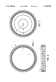
- FIG. 1 is a top view of the solar array and RF reflector combination
- FIG. 2 is a side view of FIG. 1;
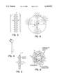
- FIG. 3 pictorially illustrates the assembly of the components of the embodiment of FIG. 1;
- FIG. 4 is a side section view of the solar array component of the embodiment of FIG. 1;
- FIG. 5 is a partial section view thereof taken along lines 4--4 in FIG. 4, drawn to a larger scale;
- FIG. 6 illustrates the solar array component in top view as deployed
- FIG. 7 pictorially illustrates folding the embodiment for stowage aboard a spacecraft.
- FIG. 8 is a pictorial that is helpful in understanding the operation of the embodiment.
- FIGS. 1 and 2 diagrammatically illustrate the new combination 1 in rear end view and side view, respectively, as deployed.
- Those skilled in the art recognize the short cylindrical skeletal structure characteristic of the deployable perimeter truss 3 constructed from various tubular members, referred to as truss members and/or longerons.
- Truss 3 supports a reflective mesh 5, which is pliant in characteristic and is reflective of microwave energy.
- the reflective mesh forms the reflector.
- the truss also supports a solar array 7. It is noted that, to better illustrate solar array 7, the truss is illustrated inverted in FIGS. 1 and 2 with its front end located at the bottom in FIG. 2 and its rear end, where solar array 7 is supported, being located at the top in the figure.
- reflector 5 is attached to the front end of truss 3 and solar array 7 is located and attached to the truss's rear end.
- solar array 7 is formed of a base of pliant material 9, suitably a film material, such as found in the prior solar arrays.
- the photovoltaic cells are electrically organized in strings as in the prior solar arrays, in series circuit to provide the appropriate voltage level desired, and, as in the prior solar arrays, the separate strings are arranged in parallel circuit to provide appropriate levels of current capacity that supplies appropriate charging levels when connected to the battery load on board the spacecraft which is somewhat flexible.
- Suitable photovoltaic cells for the present application may be constructed of amorphous silicon.
- the present invention is not concerned with the details of the photovoltaic cells or their construction into solar arrays, which is available in the technical literature and need not be here described.
- the electrical connections for the circuits in the array are formed on the base as a trace, using familiar printed circuit technique, and being thus integral with the base can be flexed or bent. So too, the amorphous silicon photovoltaic cells.
- the solar array 7 is in the shape of a thin annulus or washer-shape geometry. Its circular outer diameter is slightly less than the diameter of the truss.
- a plurality of cords 15 are evenly spaced about and tied to the outer peripheral edge of the solar array. Those cords fasten the solar array to truss 3. When deployed, the truss pulls on those cords stretching the solar array taut.
- a stretching device is used, a pair of cords 17 and 19.
- Each of the cords is threaded through holes located along the solar array's inner periphery. The holes are spaced equally about that periphery, and allow each cord to be formed into two identical equilateral triangles, forming a "Star of David".
- the cords allow the solar array to drape when the assembly is being folded into the stowed condition.
- the stretching device pulls the inner peripheral edge taut, responsive to the truss pulling the attachment cords 15 taut.
- An electrical cable 18 is carried by the array to make the electrical connection to the charging system aboard the spacecraft.
- Truss 1 is foldable. It's frame members are constructed with pivotal joints so that when the truss is to be stored, the members fold and/or pivot in unison in such a manner that the elements contract inwardly and, as viewed from an end define smaller and smaller circles, culminating in a circular ended barrel-like shape.
- One folding pattern of the solar arrays would have the array panels fold accordion style such that they would collapse into a tight ring within the folded truss. As pictorially illustrated in top view in FIG. 7, during folding up, the truss 3, folds inwardly.
- the folding array is represented pictorially in stages 3', 3" culminating in the barrel like configuration of small diameter illustrated at 3'".
- the reflective mesh 7 drapes and folds in an accordion-like manner within that barrel-like shape, occupying approximately one half the height of the barrel as folded, and solar array 7 also drapes and folds within the barrel configuration.
- the assembly receives light directly from the sun at all sun positions, except when the sun is directly perpendicular to the central axis of the reflector-solar array combination 1.
- the sun is at any position A about the left hemisphere
- the light radiation falls directly on one side of solar array 7.
- the sun is incident on the reflective mesh 5.
- the wires forming the mesh leave openings between the top and bottom surfaces of the mesh and light may pass through those openings. It may be shown that up to ninety per cent of the light that falls on the mesh, passes through.
- the mesh is said to be light permeable.
- the direct light rays are directed to the peripheral edge of the array, and, hence, do not shine upon the solar cells in the array.
- the solar array may be exposed to the sun's rays indirectly, through reflection off of other planets or orbiting bodies.
- the solar array is washer-shaped in geometry, as it is believed that the number of solar cells that fit within that geometry should be sufficient in number to produce the desired electrical power.
- the washer annulus may be made wider to incorporate additional solar cells, as appropriate, or, if necessary, be formed into a complete circular disk. Other patterns covering this area may be used where it may provide better folding geometries.
Abstract
Description
Claims (7)
Priority Applications (3)
| Application Number | Priority Date | Filing Date | Title |
|---|---|---|---|
| US09/148,130 US6150995A (en) | 1998-09-04 | 1998-09-04 | Combined photovoltaic array and RF reflector |
| JP23036599A JP3291481B2 (en) | 1998-09-04 | 1999-08-17 | Combination structure of photovoltaic array and deployable RF reflector |
| EP99115200A EP0984511A3 (en) | 1998-09-04 | 1999-08-17 | Combined photovoltaic array and RF reflector |
Applications Claiming Priority (1)
| Application Number | Priority Date | Filing Date | Title |
|---|---|---|---|
| US09/148,130 US6150995A (en) | 1998-09-04 | 1998-09-04 | Combined photovoltaic array and RF reflector |
Publications (1)
| Publication Number | Publication Date |
|---|---|
| US6150995A true US6150995A (en) | 2000-11-21 |
Family
ID=22524421
Family Applications (1)
| Application Number | Title | Priority Date | Filing Date |
|---|---|---|---|
| US09/148,130 Expired - Fee Related US6150995A (en) | 1998-09-04 | 1998-09-04 | Combined photovoltaic array and RF reflector |
Country Status (3)
| Country | Link |
|---|---|
| US (1) | US6150995A (en) |
| EP (1) | EP0984511A3 (en) |
| JP (1) | JP3291481B2 (en) |
Cited By (26)
| Publication number | Priority date | Publication date | Assignee | Title |
|---|---|---|---|---|
| US20030020667A1 (en) * | 2001-05-30 | 2003-01-30 | Essig John R. | Inflatable multi-function parabolic reflector apparatus and methods of manufacture |
| US20040207566A1 (en) * | 2001-05-30 | 2004-10-21 | Essig John Raymond | Modular inflatable multifunction field-deployable apparatus and methods of manufacture |
| US20060270301A1 (en) * | 2005-05-25 | 2006-11-30 | Northrop Grumman Corporation | Reflective surface for deployable reflector |
| US20080111031A1 (en) * | 2006-11-09 | 2008-05-15 | Northrop Grumman Space & Missions Systems Corp. | Deployable flat membrane structure |
| US20090057492A1 (en) * | 2007-08-28 | 2009-03-05 | Harris Mark A | Space vehicle having a payload-centric configuration |
| US20090133355A1 (en) * | 2007-11-27 | 2009-05-28 | Mehran Mobrem | Deployable Membrane Structure |
| WO2010011649A1 (en) * | 2008-07-21 | 2010-01-28 | Ftl Solar | Modular tensile structure with integrated photovoltaic modules |
| US20100156339A1 (en) * | 2008-12-18 | 2010-06-24 | Hoffman Roger L | Portable solar battery charger |
| US20100313878A1 (en) * | 2002-05-30 | 2010-12-16 | John Essig | Systems and methods for harnessing resources |
| US20110030757A1 (en) * | 2009-08-04 | 2011-02-10 | Industrial Technology Research Institute | Photovoltaic apparatus |
| US20120261514A1 (en) * | 2010-12-17 | 2012-10-18 | The Johns Hopkins University | System and Method of Solar Flux Concentration for Orbital Debris Remediation |
| US8474760B2 (en) | 2011-03-16 | 2013-07-02 | Stephen Leventhal | Polygonal support structure |
| US20150053255A1 (en) * | 2012-05-13 | 2015-02-26 | Leonid Goldstein | Airborne photovoltaic solar device and method |
| US20160376037A1 (en) * | 2014-05-14 | 2016-12-29 | California Institute Of Technology | Large-Scale Space-Based Solar Power Station: Packaging, Deployment and Stabilization of Lightweight Structures |
| US10454565B2 (en) | 2015-08-10 | 2019-10-22 | California Institute Of Technology | Systems and methods for performing shape estimation using sun sensors in large-scale space-based solar power stations |
| US10696428B2 (en) | 2015-07-22 | 2020-06-30 | California Institute Of Technology | Large-area structures for compact packaging |
| US10797400B1 (en) | 2019-03-14 | 2020-10-06 | Eagle Technology, Llc | High compaction ratio reflector antenna with offset optics |
| US10811759B2 (en) | 2018-11-13 | 2020-10-20 | Eagle Technology, Llc | Mesh antenna reflector with deployable perimeter |
| US10992253B2 (en) | 2015-08-10 | 2021-04-27 | California Institute Of Technology | Compactable power generation arrays |
| US11128179B2 (en) | 2014-05-14 | 2021-09-21 | California Institute Of Technology | Large-scale space-based solar power station: power transmission using steerable beams |
| US11139549B2 (en) | 2019-01-16 | 2021-10-05 | Eagle Technology, Llc | Compact storable extendible member reflector |
| US11239790B1 (en) | 2020-08-01 | 2022-02-01 | Mihai Cantemir | Solar tower system |
| US11362228B2 (en) | 2014-06-02 | 2022-06-14 | California Institute Of Technology | Large-scale space-based solar power station: efficient power generation tiles |
| US11634240B2 (en) | 2018-07-17 | 2023-04-25 | California Institute Of Technology | Coilable thin-walled longerons and coilable structures implementing longerons and methods for their manufacture and coiling |
| US11772826B2 (en) | 2018-10-31 | 2023-10-03 | California Institute Of Technology | Actively controlled spacecraft deployment mechanism |
| US11942687B2 (en) | 2019-02-25 | 2024-03-26 | Eagle Technology, Llc | Deployable reflectors |
Families Citing this family (4)
| Publication number | Priority date | Publication date | Assignee | Title |
|---|---|---|---|---|
| DE20313470U1 (en) * | 2003-08-28 | 2003-12-04 | Bruckmeier, Peter | Parabolic antenna |
| CN100345728C (en) * | 2005-10-21 | 2007-10-31 | 哈尔滨工业大学 | Truss type rigidifying solar energy cell array of inflatable expansion |
| US8508430B2 (en) * | 2010-02-01 | 2013-08-13 | Harris Corporation | Extendable rib reflector |
| CN103399580B (en) * | 2013-06-26 | 2016-01-13 | 大连理工大学 | A kind of solar tracking system of internet of things oriented application |
Citations (4)
| Publication number | Priority date | Publication date | Assignee | Title |
|---|---|---|---|---|
| US4380013A (en) * | 1981-02-17 | 1983-04-12 | General Dynamics Corp./Convair Division | Expandable panel and truss system/antenna/solar panel |
| US4475323A (en) * | 1982-04-30 | 1984-10-09 | Martin Marietta Corporation | Box truss hoop |
| US5104211A (en) * | 1987-04-09 | 1992-04-14 | Harris Corp. | Splined radial panel solar concentrator |
| US6028570A (en) * | 1998-05-18 | 2000-02-22 | Trw Inc. | Folding perimeter truss reflector |
Family Cites Families (2)
| Publication number | Priority date | Publication date | Assignee | Title |
|---|---|---|---|---|
| US5386953A (en) * | 1991-11-08 | 1995-02-07 | Calling Communications Corporation | Spacecraft designs for satellite communication system |
| US5680145A (en) * | 1994-03-16 | 1997-10-21 | Astro Aerospace Corporation | Light-weight reflector for concentrating radiation |
-
1998
- 1998-09-04 US US09/148,130 patent/US6150995A/en not_active Expired - Fee Related
-
1999
- 1999-08-17 JP JP23036599A patent/JP3291481B2/en not_active Expired - Fee Related
- 1999-08-17 EP EP99115200A patent/EP0984511A3/en not_active Withdrawn
Patent Citations (4)
| Publication number | Priority date | Publication date | Assignee | Title |
|---|---|---|---|---|
| US4380013A (en) * | 1981-02-17 | 1983-04-12 | General Dynamics Corp./Convair Division | Expandable panel and truss system/antenna/solar panel |
| US4475323A (en) * | 1982-04-30 | 1984-10-09 | Martin Marietta Corporation | Box truss hoop |
| US5104211A (en) * | 1987-04-09 | 1992-04-14 | Harris Corp. | Splined radial panel solar concentrator |
| US6028570A (en) * | 1998-05-18 | 2000-02-22 | Trw Inc. | Folding perimeter truss reflector |
Cited By (37)
| Publication number | Priority date | Publication date | Assignee | Title |
|---|---|---|---|---|
| US7382332B2 (en) | 2001-05-30 | 2008-06-03 | Essig Jr John Raymond | Modular inflatable multifunction field-deployable apparatus and methods of manufacture |
| US20040207566A1 (en) * | 2001-05-30 | 2004-10-21 | Essig John Raymond | Modular inflatable multifunction field-deployable apparatus and methods of manufacture |
| US20050103329A1 (en) * | 2001-05-30 | 2005-05-19 | Essig John R.Jr. | Inflatable multi-function parabolic reflector apparatus and methods of manufacture |
| US6897832B2 (en) | 2001-05-30 | 2005-05-24 | John R. Essig, Jr. | Inflatable multi-function parabolic reflector apparatus and methods of manufacture |
| US20030020667A1 (en) * | 2001-05-30 | 2003-01-30 | Essig John R. | Inflatable multi-function parabolic reflector apparatus and methods of manufacture |
| US20100313878A1 (en) * | 2002-05-30 | 2010-12-16 | John Essig | Systems and methods for harnessing resources |
| US20060270301A1 (en) * | 2005-05-25 | 2006-11-30 | Northrop Grumman Corporation | Reflective surface for deployable reflector |
| US20080111031A1 (en) * | 2006-11-09 | 2008-05-15 | Northrop Grumman Space & Missions Systems Corp. | Deployable flat membrane structure |
| US20090057492A1 (en) * | 2007-08-28 | 2009-03-05 | Harris Mark A | Space vehicle having a payload-centric configuration |
| US7686255B2 (en) * | 2007-08-28 | 2010-03-30 | Raytheon Company | Space vehicle having a payload-centric configuration |
| US20090133355A1 (en) * | 2007-11-27 | 2009-05-28 | Mehran Mobrem | Deployable Membrane Structure |
| WO2010011649A1 (en) * | 2008-07-21 | 2010-01-28 | Ftl Solar | Modular tensile structure with integrated photovoltaic modules |
| US20100156339A1 (en) * | 2008-12-18 | 2010-06-24 | Hoffman Roger L | Portable solar battery charger |
| US20110030757A1 (en) * | 2009-08-04 | 2011-02-10 | Industrial Technology Research Institute | Photovoltaic apparatus |
| US8373613B2 (en) | 2009-08-04 | 2013-02-12 | Industrial Technology Research Institute | Photovoltaic apparatus |
| US20120261514A1 (en) * | 2010-12-17 | 2012-10-18 | The Johns Hopkins University | System and Method of Solar Flux Concentration for Orbital Debris Remediation |
| US8873168B2 (en) * | 2010-12-17 | 2014-10-28 | The Johns Hopkins University | System and method of solar flux concentration for orbital debris remediation |
| US8474760B2 (en) | 2011-03-16 | 2013-07-02 | Stephen Leventhal | Polygonal support structure |
| US20150053255A1 (en) * | 2012-05-13 | 2015-02-26 | Leonid Goldstein | Airborne photovoltaic solar device and method |
| US9246433B2 (en) * | 2012-05-13 | 2016-01-26 | Leonid Goldstein | Airborne photovoltaic solar device and method |
| US20160376037A1 (en) * | 2014-05-14 | 2016-12-29 | California Institute Of Technology | Large-Scale Space-Based Solar Power Station: Packaging, Deployment and Stabilization of Lightweight Structures |
| US10144533B2 (en) | 2014-05-14 | 2018-12-04 | California Institute Of Technology | Large-scale space-based solar power station: multi-scale modular space power |
| US10340698B2 (en) * | 2014-05-14 | 2019-07-02 | California Institute Of Technology | Large-scale space-based solar power station: packaging, deployment and stabilization of lightweight structures |
| US11128179B2 (en) | 2014-05-14 | 2021-09-21 | California Institute Of Technology | Large-scale space-based solar power station: power transmission using steerable beams |
| US11362228B2 (en) | 2014-06-02 | 2022-06-14 | California Institute Of Technology | Large-scale space-based solar power station: efficient power generation tiles |
| US10696428B2 (en) | 2015-07-22 | 2020-06-30 | California Institute Of Technology | Large-area structures for compact packaging |
| US10454565B2 (en) | 2015-08-10 | 2019-10-22 | California Institute Of Technology | Systems and methods for performing shape estimation using sun sensors in large-scale space-based solar power stations |
| US10749593B2 (en) | 2015-08-10 | 2020-08-18 | California Institute Of Technology | Systems and methods for controlling supply voltages of stacked power amplifiers |
| US10992253B2 (en) | 2015-08-10 | 2021-04-27 | California Institute Of Technology | Compactable power generation arrays |
| US11634240B2 (en) | 2018-07-17 | 2023-04-25 | California Institute Of Technology | Coilable thin-walled longerons and coilable structures implementing longerons and methods for their manufacture and coiling |
| US11772826B2 (en) | 2018-10-31 | 2023-10-03 | California Institute Of Technology | Actively controlled spacecraft deployment mechanism |
| US10811759B2 (en) | 2018-11-13 | 2020-10-20 | Eagle Technology, Llc | Mesh antenna reflector with deployable perimeter |
| US11139549B2 (en) | 2019-01-16 | 2021-10-05 | Eagle Technology, Llc | Compact storable extendible member reflector |
| US11862840B2 (en) | 2019-01-16 | 2024-01-02 | Eagle Technologies, Llc | Compact storable extendible member reflector |
| US11942687B2 (en) | 2019-02-25 | 2024-03-26 | Eagle Technology, Llc | Deployable reflectors |
| US10797400B1 (en) | 2019-03-14 | 2020-10-06 | Eagle Technology, Llc | High compaction ratio reflector antenna with offset optics |
| US11239790B1 (en) | 2020-08-01 | 2022-02-01 | Mihai Cantemir | Solar tower system |
Also Published As
| Publication number | Publication date |
|---|---|
| JP2000091837A (en) | 2000-03-31 |
| JP3291481B2 (en) | 2002-06-10 |
| EP0984511A2 (en) | 2000-03-08 |
| EP0984511A3 (en) | 2001-08-16 |
Similar Documents
| Publication | Publication Date | Title |
|---|---|---|
| US6150995A (en) | Combined photovoltaic array and RF reflector | |
| US3735942A (en) | Space station with solar generators | |
| US11870128B2 (en) | Compactable RF membrane antenna | |
| US6104358A (en) | Low cost deployable reflector | |
| US5680145A (en) | Light-weight reflector for concentrating radiation | |
| US6028570A (en) | Folding perimeter truss reflector | |
| US9755318B2 (en) | Mesh reflector with truss structure | |
| US10811759B2 (en) | Mesh antenna reflector with deployable perimeter | |
| US7138960B2 (en) | Deployable electromagnetic concentrator | |
| WO2011006506A1 (en) | Foldable frame supporting electromagnetic radiation collectors | |
| US11411318B2 (en) | Satellite antenna having pantographic trusses and associated methods | |
| CN106887714B (en) | Inflated expanded cable net reflector antenna reflector | |
| US4074731A (en) | Compliant mesh structure and method of making same | |
| US3617113A (en) | Deployable reflector assembly | |
| JP2002220096A (en) | Storable and unfoldable framed structure | |
| US20020134423A1 (en) | Membrane-based solar array structures for spacecraft | |
| CN114503361A (en) | Antenna deployable assembly | |
| JP2015168422A (en) | Component deployment system | |
| EP3923412B1 (en) | Systems and methods for providing antennas with mechanically coupled offset posititons | |
| RU2350519C1 (en) | Space vehicle deployable bulky reflector | |
| RU2795105C1 (en) | Deployable antenna assembly | |
| US11791563B1 (en) | Deployable mesh antenna based on dome-type tensegrity | |
| JP2001099395A (en) | Unfolding structure | |
| CN213243892U (en) | Extensible solar cell panel | |
| JPS61202479A (en) | Light condensing type solar battery device |
Legal Events
| Date | Code | Title | Description |
|---|---|---|---|
| AS | Assignment |
Owner name: TRW INC., CALIFORNIA Free format text: ASSIGNMENT OF ASSIGNORS INTEREST;ASSIGNOR:GILGER, L. DWIGHT;REEL/FRAME:009447/0956 Effective date: 19980904 |
|
| AS | Assignment |
Owner name: NORTHROP GRUMMAN CORPORATION, CALIFORNIA Free format text: ASSIGNMENT OF ASSIGNORS INTEREST;ASSIGNOR:TRW, INC. N/K/A NORTHROP GRUMMAN SPACE AND MISSION SYSTEMS CORPORATION, AN OHIO CORPORATION;REEL/FRAME:013751/0849 Effective date: 20030122 Owner name: NORTHROP GRUMMAN CORPORATION,CALIFORNIA Free format text: ASSIGNMENT OF ASSIGNORS INTEREST;ASSIGNOR:TRW, INC. N/K/A NORTHROP GRUMMAN SPACE AND MISSION SYSTEMS CORPORATION, AN OHIO CORPORATION;REEL/FRAME:013751/0849 Effective date: 20030122 |
|
| FEPP | Fee payment procedure |
Free format text: PAYOR NUMBER ASSIGNED (ORIGINAL EVENT CODE: ASPN); ENTITY STATUS OF PATENT OWNER: LARGE ENTITY |
|
| FPAY | Fee payment |
Year of fee payment: 4 |
|
| FEPP | Fee payment procedure |
Free format text: PAYOR NUMBER ASSIGNED (ORIGINAL EVENT CODE: ASPN); ENTITY STATUS OF PATENT OWNER: LARGE ENTITY Free format text: PAYER NUMBER DE-ASSIGNED (ORIGINAL EVENT CODE: RMPN); ENTITY STATUS OF PATENT OWNER: LARGE ENTITY |
|
| FPAY | Fee payment |
Year of fee payment: 8 |
|
| AS | Assignment |
Owner name: NORTHROP GRUMMAN SPACE & MISSION SYSTEMS CORP.,CAL Free format text: ASSIGNMENT OF ASSIGNORS INTEREST;ASSIGNOR:NORTHROP GRUMMAN CORPORTION;REEL/FRAME:023699/0551 Effective date: 20091125 Owner name: NORTHROP GRUMMAN SPACE & MISSION SYSTEMS CORP., CA Free format text: ASSIGNMENT OF ASSIGNORS INTEREST;ASSIGNOR:NORTHROP GRUMMAN CORPORTION;REEL/FRAME:023699/0551 Effective date: 20091125 |
|
| AS | Assignment |
Owner name: NORTHROP GRUMMAN SYSTEMS CORPORATION,CALIFORNIA Free format text: ASSIGNMENT OF ASSIGNORS INTEREST;ASSIGNOR:NORTHROP GRUMMAN SPACE & MISSION SYSTEMS CORP.;REEL/FRAME:023915/0446 Effective date: 20091210 Owner name: NORTHROP GRUMMAN SYSTEMS CORPORATION, CALIFORNIA Free format text: ASSIGNMENT OF ASSIGNORS INTEREST;ASSIGNOR:NORTHROP GRUMMAN SPACE & MISSION SYSTEMS CORP.;REEL/FRAME:023915/0446 Effective date: 20091210 |
|
| REMI | Maintenance fee reminder mailed | ||
| LAPS | Lapse for failure to pay maintenance fees | ||
| STCH | Information on status: patent discontinuation |
Free format text: PATENT EXPIRED DUE TO NONPAYMENT OF MAINTENANCE FEES UNDER 37 CFR 1.362 |
|
| FP | Lapsed due to failure to pay maintenance fee |
Effective date: 20121121 |