US6058731A - Domestic clear ice maker - Google Patents
Domestic clear ice maker Download PDFInfo
- Publication number
- US6058731A US6058731A US09/263,045 US26304599A US6058731A US 6058731 A US6058731 A US 6058731A US 26304599 A US26304599 A US 26304599A US 6058731 A US6058731 A US 6058731A
- Authority
- US
- United States
- Prior art keywords
- plate
- evaporator
- shroud
- water
- sump
- Prior art date
- Legal status (The legal status is an assumption and is not a legal conclusion. Google has not performed a legal analysis and makes no representation as to the accuracy of the status listed.)
- Expired - Lifetime
Links
- XLYOFNOQVPJJNP-UHFFFAOYSA-N water Substances O XLYOFNOQVPJJNP-UHFFFAOYSA-N 0.000 claims abstract description 65
- 239000002184 metal Substances 0.000 claims abstract description 10
- 230000004888 barrier function Effects 0.000 claims description 10
- 238000005057 refrigeration Methods 0.000 claims description 6
- 238000005192 partition Methods 0.000 claims description 3
- 239000003507 refrigerant Substances 0.000 description 22
- 238000003306 harvesting Methods 0.000 description 11
- 230000008014 freezing Effects 0.000 description 8
- 238000007710 freezing Methods 0.000 description 8
- 239000007788 liquid Substances 0.000 description 6
- 239000013505 freshwater Substances 0.000 description 4
- 239000012535 impurity Substances 0.000 description 4
- 238000004519 manufacturing process Methods 0.000 description 3
- 238000000034 method Methods 0.000 description 3
- 230000008901 benefit Effects 0.000 description 2
- 238000010586 diagram Methods 0.000 description 2
- 230000000276 sedentary effect Effects 0.000 description 2
- 239000004743 Polypropylene Substances 0.000 description 1
- 238000010521 absorption reaction Methods 0.000 description 1
- 238000000151 deposition Methods 0.000 description 1
- 230000000694 effects Effects 0.000 description 1
- 239000012530 fluid Substances 0.000 description 1
- 239000006261 foam material Substances 0.000 description 1
- 238000010438 heat treatment Methods 0.000 description 1
- 230000000977 initiatory effect Effects 0.000 description 1
- 239000000463 material Substances 0.000 description 1
- 239000002991 molded plastic Substances 0.000 description 1
- 239000004033 plastic Substances 0.000 description 1
- 238000009428 plumbing Methods 0.000 description 1
- -1 polypropylene Polymers 0.000 description 1
- 229920001155 polypropylene Polymers 0.000 description 1
- 239000000725 suspension Substances 0.000 description 1
- 238000010257 thawing Methods 0.000 description 1
- 238000010792 warming Methods 0.000 description 1
Images


Classifications
-
- F—MECHANICAL ENGINEERING; LIGHTING; HEATING; WEAPONS; BLASTING
- F25—REFRIGERATION OR COOLING; COMBINED HEATING AND REFRIGERATION SYSTEMS; HEAT PUMP SYSTEMS; MANUFACTURE OR STORAGE OF ICE; LIQUEFACTION SOLIDIFICATION OF GASES
- F25C—PRODUCING, WORKING OR HANDLING ICE
- F25C1/00—Producing ice
- F25C1/12—Producing ice by freezing water on cooled surfaces, e.g. to form slabs
-
- F—MECHANICAL ENGINEERING; LIGHTING; HEATING; WEAPONS; BLASTING
- F25—REFRIGERATION OR COOLING; COMBINED HEATING AND REFRIGERATION SYSTEMS; HEAT PUMP SYSTEMS; MANUFACTURE OR STORAGE OF ICE; LIQUEFACTION SOLIDIFICATION OF GASES
- F25C—PRODUCING, WORKING OR HANDLING ICE
- F25C5/00—Working or handling ice
- F25C5/02—Apparatus for disintegrating, removing or harvesting ice
- F25C5/04—Apparatus for disintegrating, removing or harvesting ice without the use of saws
- F25C5/08—Apparatus for disintegrating, removing or harvesting ice without the use of saws by heating bodies in contact with the ice
- F25C5/10—Apparatus for disintegrating, removing or harvesting ice without the use of saws by heating bodies in contact with the ice using hot refrigerant; using fluid heated by refrigerant
-
- F—MECHANICAL ENGINEERING; LIGHTING; HEATING; WEAPONS; BLASTING
- F25—REFRIGERATION OR COOLING; COMBINED HEATING AND REFRIGERATION SYSTEMS; HEAT PUMP SYSTEMS; MANUFACTURE OR STORAGE OF ICE; LIQUEFACTION SOLIDIFICATION OF GASES
- F25C—PRODUCING, WORKING OR HANDLING ICE
- F25C1/00—Producing ice
- F25C1/18—Producing ice of a particular transparency or translucency, e.g. by injecting air
-
- F—MECHANICAL ENGINEERING; LIGHTING; HEATING; WEAPONS; BLASTING
- F25—REFRIGERATION OR COOLING; COMBINED HEATING AND REFRIGERATION SYSTEMS; HEAT PUMP SYSTEMS; MANUFACTURE OR STORAGE OF ICE; LIQUEFACTION SOLIDIFICATION OF GASES
- F25C—PRODUCING, WORKING OR HANDLING ICE
- F25C2400/00—Auxiliary features or devices for producing, working or handling ice
- F25C2400/14—Water supply
Definitions
- This invention relates to the manufacture of ice, and particularly to a small residential or domestic maker of clear ice cubes.
- Typical domestic or residential ice makers form ice cubes by depositing water into a mold attached to an evaporator and allowing the water to freeze in a sedentary state. Such an approach results in clouded ice cubes as a result of the entrapped air and impurities.
- the present invention incorporates such a flowing water system in a small unit for residential or domestic uses.
- a clear ice maker has a cabinet with an upper ice making portion and a lower bin portion.
- An evaporator assembly of a metal plate connected to an evaporator is mounted against one wall of the upper portion of the cabinet.
- the metal plate has vertical and horizontal partitions defining pockets open to the interior of the cabinet.
- a water distributor is disposed above the shroud to distribute water over all of the plate pockets.
- a trough is mounted beneath the plate and leads to a sump which receives a water pump that recirculates water from the sump to the distributor.
- an overflow pipe is disposed in the sump with an open top to control the level of water in the sump.
- the sump may be fed periodically from a water source through a controlled water fill valve.
- the sump is overfilled after each freeze cycle to wash away accumulated impurities.
- the metal plate has lateral edges projecting forward from a rear wall and a shroud surrounds the plate and has a continuous bulbous edge that engulfs the edges of the plate.
- the shroud has a roof above the plate and sloping toward the open pockets.
- the distributor has a floor with upright barriers between the front of the floor and a rear edge. The barriers distribute water that is deposited at the front of the floor to fall uniformly over the rear edge and onto the roof of the shroud.
- the shroud has a bib portion extending downwardly from plate with deflector fins that deflect ice leaving the pockets over the trough and into the bin portion.
- a refrigeration system for the clear ice maker includes an accumulator at the outlet of the evaporator and leading to a compressor.
- the refrigerator system is preferably provided with a controllable hot gas bypass between the compressor outlet and the evaporator inlet to provide hot refrigerant gas to the evaporator to loosen ice cubes formed in the pockets.
- the invention further includes a method of controlling the freezing and harvesting of ice cubes in which the temperature of the liquid refrigerant leaving the condenser of the refrigeration system is sensed at a fixed time after initiation of a freezing cycle, and the length of the freezing cycle is directly related to the sensed temperature.
- the temperature of the liquid refrigerant is again sensed at a fixed time before the end of the freezing cycle, and the length of the harvesting cycle is inversely proportional to the second sensed temperature.
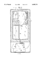
- FIG. 1 is a view in vertical section and partially in vertical elevation of an ice maker according to the present invention
- FIG. 2 is a view in vertical section taken in the plane of the line 2--2 of FIG. 1;
- FIG. 3 is a top plan view taken in the plane of the line 3--3 of FIG. 1;
- FIG. 4 is an enlarged front view of the evaporator plate assembly
- FIG. 5 is a top plan view of the evaporator plate assembly of FIG. 4;
- FIG. 6 is a view in vertical section through the evaporator plate assembly and taken in the plane of the line 6--6 of FIG. 4;
- FIG. 7 is a view in vertical section taken in the plane of the line 7--7 in FIG. 4;
- FIG. 8 is a view in horizontal section taken in the plane of the line 8--8 in FIG. 4;
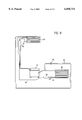
- FIG. 9 is a schematic view of the refrigerant system for the ice maker.
- FIG. 10 is a schematic diagram of the electrical system for the ice maker.
- FIG. 11 is a chart illustrating the timing of the actuation of various elements during the production and harvesting of ice.
- the clear ice maker includes a cabinet 10 with an upper forward opening 11 and a bin area 12 beneath the bottom edge of the opening 11.
- the opening 11 is closed by a door 13 that is hinged to the cabinet 10.
- Both the cabinet and door are formed of inner molded plastic members and outer formed metal members with the space filled with an insulating layer of foam material, all of which is well known in the art.
- An evaporator plate assembly indicated generally by the numeral 15 is attached to one side wall 16 of the cabinet 10 in an upper freezing portion of the cabinet.
- the evaporator plate assembly 15 includes a metal evaporator plate 17 mounted in a shroud 18.
- the evaporator plate 17 has a series of vertical and horizontal dividers 17a and 17b, respectively, which extend from a rear wall 19 and between lateral edges to divide the evaporator plate into a series of pockets. As best shown in FIG. 6, the horizontal dividers 17b slope towards the bottom front of the evaporator plate 17.
- the shroud 18 is formed of a plastic material such as a polypropylene or ABS and is molded about the evaporator plate 17. As best shown in FIGS. 6 and 8, the shroud 18 has a continuous bulbous edge 20 which engulfs the edges of the evaporator plate 17. As shown in FIG. 4, the shroud 18 has laterally extending portions 21 and 22 projecting from each end of the evaporator plate 17. A bib portion 23 of the shroud 18 is disposed beneath the bottom edge of the evaporator plate 17 and contains integral projecting deflector fins 24. Each deflector fin 24 is aligned with the center of a column of pockets in the evaporator plate 17.
- the shroud 18 also includes an inclined roof 25 disposed above the evaporator plate 17.
- a water distributor 26 is attached to the shroud wings 21 and 22 above the roof 25. As shown in FIGS. 5 and 6, the distributor 26 has a floor 27 with a central well 28 at one edge. Spaced upright barriers 29a and 29b extend from the floor 27 beyond the wall 28. A second series of spaced barriers 30a, 30b, et. sec. extend between the barriers 29a and 29b and a rear edge 31 of the floor 27. Water deposited in the wall 28 will be directed by the barriers 29 and 30 to flow uniformly over the rear edge 31 and on to the inclined roof 25. The water will thereafter flow over the roof 25 of the shroud 18, and into and over the surfaces of the pockets in evaporator plate 17.
- the shroud 18 and evaporator plate 17 with the distributor 26 attached thereto, are mounted on the inner wall of the cabinet with rivets as shown in FIGS. 4 and 8.
- An evaporator 32 is attached to the rear wall 19 of the evaporator plate 17.
- the evaporator 32 is a part of a refrigeration system shown schematically in FIG. 9.
- the evaporator 32 has an outlet line 33 which passes through an accumulator 34 to a compressor 35.
- the accumulator 34 functions in part as a reservoir for liquid refrigerant so that only gas is fed to the compressor 35.
- the output of the compressor 35 is connected to the inlet of a condenser 36 having an outlet line 37 connected to a dryer 38.
- a capillary tube 39 leads from the dryer 38 to an inlet of the evaporator 32.
- the compressor 35 draws refrigerant from the evaporator 32 and accumulator 34 and discharges the refrigerant under increased pressure and temperature to the condenser 36.
- the hot refrigerant gas entering the condenser 36 is cooled by air circulated by a fan 40.
- the refrigerant in the condenser 36 liquefies.
- the capillary tube 39 maintains the high pressure in the condenser 36 and at the compressor outlet while providing substantially reduced pressure in the evaporator 32.
- the substantially reduced pressure in the evaporator 32 results in a large temperature drop and subsequent absorption of heat by the evaporator 32.
- the refrigeration system of FIG. 9 includes a hot gas bypass valve 42 disposed in a line 43 between the outlet of the compressor 35 and the inlet of the evaporator 32.
- a hot gas bypass valve 42 When the hot gas bypass valve 42 is opened, hot refrigerant will enter the evaporator 32, thereby heating the evaporator plate 17.
- Such a hot gas bypass system is described in U.S. Pat. No. 5,065,584 issued Nov. 19, 1991, for "Hot Gas Bypass Defrosting System".
- the compressor 35, condenser 36, and fan 40 are located at the bottom of the cabinet 10 beneath the insulated portion, as shown in FIGS. 1 and 3.
- a water sump 50 has a trough portion 51 extending beneath the evaporator plate assembly 15.
- the trough 51 extends along the one side wall of the cabinet, along a rear wall, and to an opposite side wall of the cabinet.
- the bottom of the trough portion slopes downwardly to the level of a well 52 in which the inlet 53 of a water pump 54 is mounted.
- the outlet of the water pump 54 is connected to the well 28 in the distributor 26.
- An overflow pipe 55 extends into the sump 50 and leads to a stand pipe 56.
- the overflow pipe is removable.
- the stand pipe 56 opens to a drain 57 in the bottom of the bin area 12 in the cabinet 10.
- the drain 57 can be connected to a drain in the home plumbing. Alternatively, the drain 57 may lead to an overflow collector 58 in the space beneath the insulated portion of the cabinet 10.
- Fresh water from an external source may be provided periodically to the sump 50 through a water fill valve 59.
- water from the sump 50 is pumped by the pump 54 to the distributor 26 which delivers a cascade of water over the surfaces of the evaporator plate 17.
- the evaporator 32 When the evaporator 32 is connected to receive liquefied refrigerant from the condenser 36, the water cascading over the surface of the evaporator plate 17 will freeze forming cubes of ice in the pockets The pure water freezes first and impurities in the water will be left in suspension in the flowing water.
- the hot gas bypass valve 42 is opened and heated refrigerant is delivered to the evaporator 32, thereby warming the surface of the evaporator plate 17 until the ice cubes dislodge from the evaporator plate 17.
- the dislodged ice cubes will fall into the bin area 12 and are directed away from the trough portion 51 of the sump 50 by the fins 24. Not all water cascading over the surface of the evaporator plate will freeze. The excess water is collected in the trough 51 and returned to the well 52 where it is recirculated to the distributor 26 by the pump 54. After each freezing cycle, a charge of fresh water is delivered to the sump by the water fill valve 59 to dilute the water with impurities and flush through the overflow pipe 55.
- FIG. 10 is a schematic diagram of the electrical system for controlling the operation of the compressor motor 35, a solenoid 60 for the hot gas bypass valve 42, the condenser fan 40, the water pump 54, and a solenoid 61 that controls the fresh water inlet valve 59.
- the operation of the motors and solenoids are controlled by a microprocessor based control 66 that responds to a bin thermostat 62 disposed in the bin 12 in the cabinet 10, a toggle switch 63, a thermistor 64 disposed in the outlet line from the condenser 36, and an optional overflow circuit 65.
- the toggle switch 63 is a three-position switch. In one position, the machine will be in the "ice” mode. In a center position, the machine will be in the "off” mode in which all outputs from the control 66 are de-energized. In the third position of the toggle switch 63, the machine will be in a "clean" mode. On initial start-up or restarting with the bin thermostat 62 closed, the toggle switch 63 is placed into the "ice” mode position. This will have the effect of energizing the hot gas bypass solenoid 60 and the water inlet valve solenoid 61 for a period of time. This will fill the sump 50 with fresh water to the level of the overflow pipe 55.
- the compressor 33, the condenser fan 40, and the water circulation pump 54 are energized.
- the water fill valve solenoid 61 and the hot gas valve solenoid 60 are de-energized. The machine is now in a freeze cycle.
- a reading of the liquid refrigerant temperature sensed by the thermistor 64 is taken.
- the temperature will be reflective of the temperature of the surrounding environment. This temperature reading will determine the remaining length of time for the freeze cycle.
- the length of the freeze cycle is adjusted directly based upon the sensed temperature. That is, the higher the temperature of the liquid refrigerant, the longer the freeze cycle. For example, if the liquid refrigerant temperature is 80° F., the total freeze time will be 10.5 minutes. If the sensed temperature is 100° F., the total freeze time will be 17 minutes, At a temperature of 120° F., the freeze time will be 26 minutes. The machine will cease operation if the temperature reaches 175° F.
- An adjustable potentiometer 70 is located on the control board 66 to add or subtract up to five minutes from the overall freeze time.
- the water pump 54 and fan 40 are de-energized and the hot gas solenoid 60 and water inlet solenoid 61 are energized.
- the compressor remains energized.
- the hot refrigerant gas flowing through the evaporator 17 will loosen the ice formed in the pockets so that the ice is harvested.
- a second temperature reading from the thermistor 64 is taken to determine the length of the harvest cycle, which can also vary depending upon the operating environment.
- the length of the harvest cycle is adjusted inversely based upon the second sensed temperature. For example, if the second sensed temperature is 80° F., a harvest cycle of 2 minutes will be used. If the temperature is 100° F. or above, the harvest cycle will be reduced in time to 1.5 minutes.
- the control returns to a new freeze cycle with the compressor, water pump, and condenser fan motors all energized and with the hot gas and water inlet solenoids de-energized.
- the initial start-up, freeze, and harvest cycles are illustrated graphically on FIG. 11.
- the machine will continue to cycle through freeze and harvest cycles until the bin thermostat 62 opens, which will remove power to the control. When the bin thermostat 62 recloses, the machine will restart in the cycle shown in FIG. 11.
- the bin thermostat 62 is located at an upper portion of the bin 12. The bin thermostat 62 responds to the level of ice cubes in the bin 12.
- the optional overflow collector 58 includes a pump 67 that is actuated by a float controlled switch to periodically empty the collector 58.
- a second overflow switch 65 is located in the collector 58 at a higher level. The overflow switch 65 is closed when the water in the collector 58 rises to a level that indicates that the pump is not working. When the overflow switch 65 closes, the machine will stop operating.
- An LED light 68 is mounted on the control board 66 and is connected to the circuit for the thermistor 64.
- the circuit for the thermistor 64 When the circuit for the thermistor 64 is closed, the light 68 will be continuously lit. When the circuit for the thermistor 64 is open, the light 68 will flash at a slow rate. When the thermistor 64 senses an abnormally high fluid refrigerant temperature, such as 175° F., the light 68 will flash at a rapid rate. If the light 68 is off, it indicates that power to the control board 66 has been turned off by the toggle switch 63 or that the overflow switch 65 has interrupted the power to the machine. In this manner, the light 68 functions as a diagnostic aide for servicing the machine.
Landscapes
- Engineering & Computer Science (AREA)
- Physics & Mathematics (AREA)
- Mechanical Engineering (AREA)
- Thermal Sciences (AREA)
- General Engineering & Computer Science (AREA)
- Production, Working, Storing, Or Distribution Of Ice (AREA)
Abstract
Description
Claims (12)
Priority Applications (2)
| Application Number | Priority Date | Filing Date | Title |
|---|---|---|---|
| US09/263,045 US6058731A (en) | 1997-04-01 | 1999-03-05 | Domestic clear ice maker |
| US09/547,840 US6148621A (en) | 1997-04-01 | 2000-04-12 | Domestic clear ice maker |
Applications Claiming Priority (3)
| Application Number | Priority Date | Filing Date | Title |
|---|---|---|---|
| US08/828,761 US5878583A (en) | 1997-04-01 | 1997-04-01 | Ice making machine and control method therefore |
| US8214598P | 1998-04-17 | 1998-04-17 | |
| US09/263,045 US6058731A (en) | 1997-04-01 | 1999-03-05 | Domestic clear ice maker |
Related Parent Applications (1)
| Application Number | Title | Priority Date | Filing Date |
|---|---|---|---|
| US08/828,761 Continuation US5878583A (en) | 1997-04-01 | 1997-04-01 | Ice making machine and control method therefore |
Related Child Applications (1)
| Application Number | Title | Priority Date | Filing Date |
|---|---|---|---|
| US09/547,840 Division US6148621A (en) | 1997-04-01 | 2000-04-12 | Domestic clear ice maker |
Publications (1)
| Publication Number | Publication Date |
|---|---|
| US6058731A true US6058731A (en) | 2000-05-09 |
Family
ID=25252678
Family Applications (3)
| Application Number | Title | Priority Date | Filing Date |
|---|---|---|---|
| US08/828,761 Expired - Lifetime US5878583A (en) | 1997-04-01 | 1997-04-01 | Ice making machine and control method therefore |
| US09/263,045 Expired - Lifetime US6058731A (en) | 1997-04-01 | 1999-03-05 | Domestic clear ice maker |
| US09/547,840 Expired - Lifetime US6148621A (en) | 1997-04-01 | 2000-04-12 | Domestic clear ice maker |
Family Applications Before (1)
| Application Number | Title | Priority Date | Filing Date |
|---|---|---|---|
| US08/828,761 Expired - Lifetime US5878583A (en) | 1997-04-01 | 1997-04-01 | Ice making machine and control method therefore |
Family Applications After (1)
| Application Number | Title | Priority Date | Filing Date |
|---|---|---|---|
| US09/547,840 Expired - Lifetime US6148621A (en) | 1997-04-01 | 2000-04-12 | Domestic clear ice maker |
Country Status (6)
| Country | Link |
|---|---|
| US (3) | US5878583A (en) |
| EP (1) | EP0869321B1 (en) |
| JP (1) | JPH10281603A (en) |
| CN (1) | CN1092786C (en) |
| DE (1) | DE69822021T2 (en) |
| ES (1) | ES2217504T3 (en) |
Cited By (28)
| Publication number | Priority date | Publication date | Assignee | Title |
|---|---|---|---|---|
| US6351963B2 (en) * | 2000-01-05 | 2002-03-05 | Jeffrey A. Surber | Refrigerated speed rail apparatus |
| US6405553B1 (en) * | 2000-12-06 | 2002-06-18 | Mark E. Willett | Wall mounted ice making machine |
| US6438976B2 (en) | 1999-10-08 | 2002-08-27 | General Electric Company | Icemaker assembly |
| US6718793B2 (en) * | 2001-07-07 | 2004-04-13 | Lg Electronics, Inc. | Refrigerator incorporating condenser functioning as backcover |
| US20040226311A1 (en) * | 2003-04-11 | 2004-11-18 | Hoshizaki Denki Kabushiki Kaisha | Ice-making mechanism of ice-making machine |
| US20050044875A1 (en) * | 2003-08-29 | 2005-03-03 | Manitowoc Foodservice Companies, Inc. | Low-volume ice making machine |
| US20050109056A1 (en) * | 2003-11-21 | 2005-05-26 | Rand Thomas W. | Clear ice making refrigerator |
| US20060277928A1 (en) * | 2005-06-14 | 2006-12-14 | Manitowoc Foodservice Companies | Residential ice machine |
| US20070193299A1 (en) * | 2005-09-02 | 2007-08-23 | Landers Jerry L | Ice/beverage dispenser with in-line ice crusher |
| US20070273259A1 (en) * | 2006-05-24 | 2007-11-29 | Hoshizaki America, Inc. | Methods and Apparatus to Reduce or Prevent Bridging in an Ice Storage Bin |
| US20080059003A1 (en) * | 2006-08-30 | 2008-03-06 | Doberstein Andrew J | Cooling unit with data logging control |
| US20080092567A1 (en) * | 2006-10-20 | 2008-04-24 | Doberstein Andrew J | Ice maker with ice bin level control |
| US20080092574A1 (en) * | 2006-10-20 | 2008-04-24 | Doberstein Andrew J | Cooler with multi-parameter cube ice maker control |
| US20080092569A1 (en) * | 2006-10-20 | 2008-04-24 | Doberstein Andrew J | Cooling unit with multi-parameter defrost control |
| US20080156019A1 (en) * | 2006-12-29 | 2008-07-03 | Baranowski Philip J | Ice making machine and method |
| US20090282855A1 (en) * | 2008-05-16 | 2009-11-19 | Hoshizaki America, Inc. | Under counter ice making machine |
| US20100011801A1 (en) * | 2008-07-17 | 2010-01-21 | Ritchie Sheena L | Refrigerator with select temperature compartment |
| US8087533B2 (en) | 2006-05-24 | 2012-01-03 | Hoshizaki America, Inc. | Systems and methods for providing a removable sliding access door for an ice storage bin |
| US20170051920A1 (en) * | 2015-08-18 | 2017-02-23 | Steven Harris Lenz | System for providing a combined fireplace and waterfall |
| US9782524B2 (en) | 2005-12-14 | 2017-10-10 | Stryker Corporation | Surgical waste collection unit with a manifold receiver that is offset relative to the horizontal |
| US10254032B2 (en) | 2016-07-15 | 2019-04-09 | True Manufacturing Co., Inc. | Ice discharging apparatus for vertical spray-type ice machines |
| US10415865B2 (en) | 2012-10-08 | 2019-09-17 | Whirlpool Corporation | Refrigerator with wet ice storage |
| US10471188B1 (en) | 2019-04-12 | 2019-11-12 | Stryker Corporation | Manifold for filtering medical waste being drawn under vacuum into a medical waste collection system |
| WO2020248796A1 (en) * | 2019-06-11 | 2020-12-17 | 合肥美的电冰箱有限公司 | Control method and control apparatus for refrigerator ice making, and refrigerator |
| USD919799S1 (en) | 2019-11-11 | 2021-05-18 | Stryker Corporation | Manifold housing for a medical waste collection device |
| US11318242B2 (en) | 2019-04-12 | 2022-05-03 | Stryker Corporation | Manifold for a medical waste collection system |
| USD956967S1 (en) | 2019-11-11 | 2022-07-05 | Stryker Corporation | Manifold housing for a medical waste collection device |
| USD996640S1 (en) | 2019-11-11 | 2023-08-22 | Stryker Corporation | Specimen collection tray |
Families Citing this family (67)
| Publication number | Priority date | Publication date | Assignee | Title |
|---|---|---|---|---|
| CA2271632C (en) * | 1998-05-15 | 2007-03-27 | Imi Cornelius Inc. | Low profile ice maker |
| US6425258B1 (en) | 2000-12-08 | 2002-07-30 | Hoshizaki America, Inc. | Ice guide for an ice making machine |
| US6349556B1 (en) | 2000-12-08 | 2002-02-26 | Hoshizaki America, Inc. | Water tank for ice making machine |
| KR100430923B1 (en) * | 2001-01-17 | 2004-05-20 | 최재숙 | Device for manufacturing forzen sweet by a Quick Freezing and Melting |
| US7195744B2 (en) * | 2001-08-28 | 2007-03-27 | Ecolab, Inc. | Device for holding a container for a composition that produces an antimicrobially active gas |
| US6869518B2 (en) * | 2002-06-12 | 2005-03-22 | Ecolab Inc. | Electrochemical generation of chlorine dioxide |
| US6619051B1 (en) | 2002-07-12 | 2003-09-16 | Ecolab Inc. | Integrated cleaning and sanitizing system and method for ice machines |
| US7285255B2 (en) * | 2002-12-10 | 2007-10-23 | Ecolab Inc. | Deodorizing and sanitizing employing a wicking device |
| US20070157636A1 (en) * | 2003-03-13 | 2007-07-12 | Billman Gregory M | Icemaker control system |
| JP2004354017A (en) * | 2003-05-30 | 2004-12-16 | Sanyo Electric Co Ltd | Cooling device |
| US20070227171A1 (en) * | 2003-06-24 | 2007-10-04 | Mcmillan Robert B | Enhanced water system for evaporative coolers |
| JP2005043014A (en) * | 2003-07-24 | 2005-02-17 | Hoshizaki Electric Co Ltd | Operation method of automatic ice making machine |
| KR20040052964A (en) * | 2004-05-21 | 2004-06-23 | 최재숙 | Device for manufacturing frozen sweet by a quick freezing and melting |
| US7340913B2 (en) * | 2004-08-05 | 2008-03-11 | Manitowoc Foodservice Companies, Inc. | Ice machine and ice-making assembly including a water distributor |
| US8157951B2 (en) * | 2005-10-11 | 2012-04-17 | Applied Materials, Inc. | Capacitively coupled plasma reactor having very agile wafer temperature control |
| US7988872B2 (en) * | 2005-10-11 | 2011-08-02 | Applied Materials, Inc. | Method of operating a capacitively coupled plasma reactor with dual temperature control loops |
| US8092638B2 (en) * | 2005-10-11 | 2012-01-10 | Applied Materials Inc. | Capacitively coupled plasma reactor having a cooled/heated wafer support with uniform temperature distribution |
| US8034180B2 (en) * | 2005-10-11 | 2011-10-11 | Applied Materials, Inc. | Method of cooling a wafer support at a uniform temperature in a capacitively coupled plasma reactor |
| US8012304B2 (en) * | 2005-10-20 | 2011-09-06 | Applied Materials, Inc. | Plasma reactor with a multiple zone thermal control feed forward control apparatus |
| JP5008675B2 (en) * | 2006-11-02 | 2012-08-22 | ホシザキ電機株式会社 | Automatic ice maker and its operating method |
| BRPI0700228A (en) | 2007-02-05 | 2008-09-23 | Whirlpool Sa | finger type evaporator |
| US20120005100A1 (en) * | 2009-03-09 | 2012-01-05 | Toshiba Solutions Corporation | Car navigation system and individual functional device |
| US8171744B2 (en) * | 2009-06-30 | 2012-05-08 | General Electric Company | Method and apparatus for controlling temperature for forming ice within an icemaker compartment of a refrigerator |
| US20120125018A1 (en) * | 2010-11-19 | 2012-05-24 | General Electric Company | Ice dispenser system for a refrigeration appliance, refrigeration appliance, and method of making ice |
| JP2014504718A (en) * | 2011-01-31 | 2014-02-24 | マニトワック・フードサービス・カンパニーズ・エルエルシー | Refrigeration and harvest control in safe mode of ice making machine and method thereof |
| US9003824B2 (en) * | 2011-02-02 | 2015-04-14 | Robert Almblad | Positive air pressure ice making and dispensing system |
| WO2012106484A2 (en) | 2011-02-02 | 2012-08-09 | Robert Amblad | Positive air pressure ice making and dispensing system |
| JP6043497B2 (en) * | 2012-04-06 | 2016-12-14 | ホシザキ株式会社 | How to operate an automatic ice machine |
| US9513045B2 (en) | 2012-05-03 | 2016-12-06 | Whirlpool Corporation | Heater-less ice maker assembly with a twistable tray |
| US10107538B2 (en) | 2012-09-10 | 2018-10-23 | Hoshizaki America, Inc. | Ice cube evaporator plate assembly |
| US8925335B2 (en) | 2012-11-16 | 2015-01-06 | Whirlpool Corporation | Ice cube release and rapid freeze using fluid exchange apparatus and methods |
| US9476629B2 (en) | 2012-12-13 | 2016-10-25 | Whirlpool Corporation | Clear ice maker and method for forming clear ice |
| US9273891B2 (en) | 2012-12-13 | 2016-03-01 | Whirlpool Corporation | Rotational ice maker |
| US9599385B2 (en) | 2012-12-13 | 2017-03-21 | Whirlpool Corporation | Weirless ice tray |
| US9518773B2 (en) | 2012-12-13 | 2016-12-13 | Whirlpool Corporation | Clear ice maker |
| US9599388B2 (en) | 2012-12-13 | 2017-03-21 | Whirlpool Corporation | Clear ice maker with varied thermal conductivity |
| US9303903B2 (en) | 2012-12-13 | 2016-04-05 | Whirlpool Corporation | Cooling system for ice maker |
| US9470448B2 (en) | 2012-12-13 | 2016-10-18 | Whirlpool Corporation | Apparatus to warm plastic side of mold |
| US9410723B2 (en) | 2012-12-13 | 2016-08-09 | Whirlpool Corporation | Ice maker with rocking cold plate |
| US9518770B2 (en) | 2012-12-13 | 2016-12-13 | Whirlpool Corporation | Multi-sheet spherical ice making |
| US9310115B2 (en) | 2012-12-13 | 2016-04-12 | Whirlpool Corporation | Layering of low thermal conductive material on metal tray |
| US9500398B2 (en) | 2012-12-13 | 2016-11-22 | Whirlpool Corporation | Twist harvest ice geometry |
| US9557087B2 (en) | 2012-12-13 | 2017-01-31 | Whirlpool Corporation | Clear ice making apparatus having an oscillation frequency and angle |
| US9863682B2 (en) | 2013-01-30 | 2018-01-09 | True Manufacturing Company, Inc. | Water distribution for an ice maker |
| AU2014201376B2 (en) * | 2013-03-15 | 2016-07-14 | Manitowoc Foodservice Companies, Llc | A method and system for controlling the initiation of a freeze cycle pre-set time in an ice maker |
| CN104122846B (en) * | 2013-04-24 | 2016-12-28 | 武汉航空仪表有限责任公司 | A kind of icing tunnel or the temperature stabilization methods of freezing weather room icing tests |
| MX371063B (en) * | 2014-01-08 | 2020-01-15 | True Mfg Co Inc | Variable-operating point components for cube ice machines. |
| US10502477B2 (en) | 2014-07-28 | 2019-12-10 | Haier Us Appliance Solutions, Inc. | Refrigerator appliance |
| KR102279393B1 (en) | 2014-08-22 | 2021-07-21 | 삼성전자주식회사 | Refrigerator |
| WO2016065269A2 (en) | 2014-10-23 | 2016-04-28 | Whirlpool Corporation | Method and apparatus for increasing rate of ice production in an automatic ice maker |
| WO2016164165A1 (en) | 2015-04-09 | 2016-10-13 | True Manufacturing Co., Inc. | Methods and apparatuses for controlling the harvest cycle of an ice maker using a harvest sensor and a temperature sensor |
| MX2017014452A (en) * | 2015-05-11 | 2018-03-16 | True Mfg Co Inc | Ice maker with push notification to indicate when maintenance is required. |
| WO2017112758A1 (en) * | 2015-12-21 | 2017-06-29 | True Manufacturing Co., Inc. | Ice machine with a dual-circuit evaporator for hydrocarbon refrigerant |
| TR201611228A1 (en) | 2016-08-10 | 2018-03-21 | Arcelik As | TRANSPARENT ICE GENERATION EQUIPMENT FOR REFRIGERATION DEVICES AND ITS CONTROL METHOD |
| US10605493B2 (en) * | 2017-01-26 | 2020-03-31 | Haier Us Appliance Solutions, Inc. | Refrigerator appliance with a clear icemaker |
| US10571179B2 (en) * | 2017-01-26 | 2020-02-25 | Haier Us Appliance Solutions, Inc. | Refrigerator appliance with a clear icemaker |
| KR101867094B1 (en) * | 2017-03-06 | 2018-06-14 | 주식회사 아이스트로 | Ice making machine |
| CN107449194B (en) * | 2017-03-29 | 2019-09-13 | 浙江优仕德塑业有限公司 | A kind of ice cube moulding equipment |
| CN106839553B (en) * | 2017-03-29 | 2019-08-20 | 台州市黄岩盛光塑料厂 | A kind of ice cube plastication device |
| CN107449193B (en) * | 2017-03-29 | 2019-09-10 | 利辛县雨若信息科技有限公司 | A kind of moulding equipment for ice cube |
| CN106839551A (en) * | 2017-04-07 | 2017-06-13 | 中山市大毅电器科技有限公司 | Self-draining ice machine |
| US10739053B2 (en) | 2017-11-13 | 2020-08-11 | Whirlpool Corporation | Ice-making appliance |
| US11255588B2 (en) | 2018-08-03 | 2022-02-22 | Hoshizaki America, Inc. | Ultrasonic bin control in an ice machine |
| US10907874B2 (en) | 2018-10-22 | 2021-02-02 | Whirlpool Corporation | Ice maker downspout |
| JP6760361B2 (en) * | 2018-12-27 | 2020-09-23 | ダイキン工業株式会社 | Operation control method of ice machine |
| US11255593B2 (en) * | 2019-06-19 | 2022-02-22 | Haier Us Appliance Solutions, Inc. | Ice making assembly including a sealed system for regulating the temperature of the ice mold |
| US11656017B2 (en) * | 2020-01-18 | 2023-05-23 | True Manufacturing Co., Inc. | Ice maker |
Citations (11)
| Publication number | Priority date | Publication date | Assignee | Title |
|---|---|---|---|---|
| US2645910A (en) * | 1949-12-09 | 1953-07-21 | Flakice Corp | Ice-making apparatus and method |
| US2836038A (en) * | 1954-03-01 | 1958-05-27 | Carrier Corp | Ice making apparatus |
| US3021686A (en) * | 1960-06-20 | 1962-02-20 | Carrier Corp | Ice making |
| US3144755A (en) * | 1961-07-24 | 1964-08-18 | Kattis Theodore | Small block ice making machine |
| US3171266A (en) * | 1961-07-06 | 1965-03-02 | Weisco Products Corp | Ice making machine with water distribution means |
| US3423952A (en) * | 1967-03-10 | 1969-01-28 | Lloyd R Pugh | Ice making apparatus |
| US3430452A (en) * | 1966-12-05 | 1969-03-04 | Manitowoc Co | Ice cube making apparatus |
| US4458503A (en) * | 1980-05-16 | 1984-07-10 | King-Seeley Thermos Co. | Ice product and method and apparatus for making same |
| US4722199A (en) * | 1985-12-09 | 1988-02-02 | Hoshizaki Electric Co., Ltd. | Thermally insulated bin structure |
| US5065584A (en) * | 1990-07-30 | 1991-11-19 | U-Line Corporation | Hot gas bypass defrosting system |
| US5586439A (en) * | 1992-12-11 | 1996-12-24 | The Manitowoc Company, Inc. | Ice making machine |
Family Cites Families (14)
| Publication number | Priority date | Publication date | Assignee | Title |
|---|---|---|---|---|
| US4442681A (en) * | 1981-09-28 | 1984-04-17 | Fischer Harry C | Ice-maker |
| US4412429A (en) * | 1981-11-27 | 1983-11-01 | Mcquay Inc. | Ice cube making |
| KR910002810Y1 (en) * | 1988-10-06 | 1991-05-02 | 삼성전자 주식회사 | Evaporator for ice-maker |
| KR910003551Y1 (en) * | 1989-03-03 | 1991-05-31 | 삼성전자 주식회사 | Evaporator for ice-maker |
| US5129237A (en) * | 1989-06-26 | 1992-07-14 | Servend International, Inc. | Ice making machine with freeze and harvest control |
| US4947653A (en) * | 1989-06-26 | 1990-08-14 | Hussmann Corporation | Ice making machine with freeze and harvest control |
| US5193357A (en) * | 1990-06-07 | 1993-03-16 | The Manitowoc Company, Inc. | Ice machine with improved evaporator/ice forming assembly |
| JP3067175B2 (en) * | 1990-08-06 | 2000-07-17 | ホシザキ電機株式会社 | Ice machine |
| US5257506A (en) * | 1991-03-22 | 1993-11-02 | Carrier Corporation | Defrost control |
| US5182925A (en) * | 1991-05-13 | 1993-02-02 | Mile High Equipment Company | Integrally formed, modular ice cuber having a stainless steel evaporator and microcontroller |
| KR970002812B1 (en) * | 1992-02-25 | 1997-03-11 | 산요덴끼 가부시기가이샤 | Flow-type ice manufacturing machine |
| US5419151A (en) * | 1992-05-29 | 1995-05-30 | Hoshizaki Denki Kabushiki Kaisha | Ice making machine |
| JP3054535B2 (en) * | 1994-02-22 | 2000-06-19 | 三洋電機株式会社 | Ice machine |
| JP3573911B2 (en) * | 1997-03-31 | 2004-10-06 | 三洋電機株式会社 | Ice machine control device |
-
1997
- 1997-04-01 US US08/828,761 patent/US5878583A/en not_active Expired - Lifetime
-
1998
- 1998-03-23 EP EP98302147A patent/EP0869321B1/en not_active Expired - Lifetime
- 1998-03-23 DE DE69822021T patent/DE69822021T2/en not_active Expired - Lifetime
- 1998-03-23 ES ES98302147T patent/ES2217504T3/en not_active Expired - Lifetime
- 1998-04-01 JP JP10088946A patent/JPH10281603A/en active Pending
- 1998-04-01 CN CN98108820.1A patent/CN1092786C/en not_active Expired - Fee Related
-
1999
- 1999-03-05 US US09/263,045 patent/US6058731A/en not_active Expired - Lifetime
-
2000
- 2000-04-12 US US09/547,840 patent/US6148621A/en not_active Expired - Lifetime
Patent Citations (11)
| Publication number | Priority date | Publication date | Assignee | Title |
|---|---|---|---|---|
| US2645910A (en) * | 1949-12-09 | 1953-07-21 | Flakice Corp | Ice-making apparatus and method |
| US2836038A (en) * | 1954-03-01 | 1958-05-27 | Carrier Corp | Ice making apparatus |
| US3021686A (en) * | 1960-06-20 | 1962-02-20 | Carrier Corp | Ice making |
| US3171266A (en) * | 1961-07-06 | 1965-03-02 | Weisco Products Corp | Ice making machine with water distribution means |
| US3144755A (en) * | 1961-07-24 | 1964-08-18 | Kattis Theodore | Small block ice making machine |
| US3430452A (en) * | 1966-12-05 | 1969-03-04 | Manitowoc Co | Ice cube making apparatus |
| US3423952A (en) * | 1967-03-10 | 1969-01-28 | Lloyd R Pugh | Ice making apparatus |
| US4458503A (en) * | 1980-05-16 | 1984-07-10 | King-Seeley Thermos Co. | Ice product and method and apparatus for making same |
| US4722199A (en) * | 1985-12-09 | 1988-02-02 | Hoshizaki Electric Co., Ltd. | Thermally insulated bin structure |
| US5065584A (en) * | 1990-07-30 | 1991-11-19 | U-Line Corporation | Hot gas bypass defrosting system |
| US5586439A (en) * | 1992-12-11 | 1996-12-24 | The Manitowoc Company, Inc. | Ice making machine |
Cited By (46)
| Publication number | Priority date | Publication date | Assignee | Title |
|---|---|---|---|---|
| US7426838B1 (en) | 1999-10-08 | 2008-09-23 | General Electric Company | Icemaker assembly |
| US6438976B2 (en) | 1999-10-08 | 2002-08-27 | General Electric Company | Icemaker assembly |
| US6351963B2 (en) * | 2000-01-05 | 2002-03-05 | Jeffrey A. Surber | Refrigerated speed rail apparatus |
| US6405553B1 (en) * | 2000-12-06 | 2002-06-18 | Mark E. Willett | Wall mounted ice making machine |
| US6718793B2 (en) * | 2001-07-07 | 2004-04-13 | Lg Electronics, Inc. | Refrigerator incorporating condenser functioning as backcover |
| US20040226311A1 (en) * | 2003-04-11 | 2004-11-18 | Hoshizaki Denki Kabushiki Kaisha | Ice-making mechanism of ice-making machine |
| US7010933B2 (en) * | 2003-04-11 | 2006-03-14 | Hoshizaki Denki Kabushiki Kaisha | Ice-making mechanism of ice-making machine |
| US20050044875A1 (en) * | 2003-08-29 | 2005-03-03 | Manitowoc Foodservice Companies, Inc. | Low-volume ice making machine |
| US7082782B2 (en) | 2003-08-29 | 2006-08-01 | Manitowoc Foodservice Companies, Inc. | Low-volume ice making machine |
| US20050109056A1 (en) * | 2003-11-21 | 2005-05-26 | Rand Thomas W. | Clear ice making refrigerator |
| US7062936B2 (en) | 2003-11-21 | 2006-06-20 | U-Line Corporation | Clear ice making refrigerator |
| US20060277928A1 (en) * | 2005-06-14 | 2006-12-14 | Manitowoc Foodservice Companies | Residential ice machine |
| US7281386B2 (en) | 2005-06-14 | 2007-10-16 | Manitowoc Foodservice Companies, Inc. | Residential ice machine |
| US7802444B2 (en) | 2005-09-02 | 2010-09-28 | Manitowoc Foodservice Companies, Llc | Ice/beverage dispenser with in-line ice crusher |
| US20070193299A1 (en) * | 2005-09-02 | 2007-08-23 | Landers Jerry L | Ice/beverage dispenser with in-line ice crusher |
| US11801108B2 (en) | 2005-12-14 | 2023-10-31 | Stryker Corporation | Methods of assembling a manifold for a medical waste collection system |
| US11684442B2 (en) | 2005-12-14 | 2023-06-27 | Stryker Corporation | Methods of assembling a manifold for a medical waste collection system |
| US11045590B2 (en) | 2005-12-14 | 2021-06-29 | Stryker Corporation | Removable manifold for a medical/surgical waste collection unit |
| US10722617B2 (en) | 2005-12-14 | 2020-07-28 | Stryker Corporation | Manifold including a data carrier for a medical/surgical waste collection assembly |
| US9782524B2 (en) | 2005-12-14 | 2017-10-10 | Stryker Corporation | Surgical waste collection unit with a manifold receiver that is offset relative to the horizontal |
| US7739879B2 (en) | 2006-05-24 | 2010-06-22 | Hoshizaki America, Inc. | Methods and apparatus to reduce or prevent bridging in an ice storage bin |
| US20070273259A1 (en) * | 2006-05-24 | 2007-11-29 | Hoshizaki America, Inc. | Methods and Apparatus to Reduce or Prevent Bridging in an Ice Storage Bin |
| US8087533B2 (en) | 2006-05-24 | 2012-01-03 | Hoshizaki America, Inc. | Systems and methods for providing a removable sliding access door for an ice storage bin |
| US7878009B2 (en) | 2006-08-30 | 2011-02-01 | U-Line Corporation | Cooling unit with data logging control |
| US20080059003A1 (en) * | 2006-08-30 | 2008-03-06 | Doberstein Andrew J | Cooling unit with data logging control |
| US20080092569A1 (en) * | 2006-10-20 | 2008-04-24 | Doberstein Andrew J | Cooling unit with multi-parameter defrost control |
| US20080092574A1 (en) * | 2006-10-20 | 2008-04-24 | Doberstein Andrew J | Cooler with multi-parameter cube ice maker control |
| US20080092567A1 (en) * | 2006-10-20 | 2008-04-24 | Doberstein Andrew J | Ice maker with ice bin level control |
| US20080156019A1 (en) * | 2006-12-29 | 2008-07-03 | Baranowski Philip J | Ice making machine and method |
| US7832219B2 (en) | 2006-12-29 | 2010-11-16 | Manitowoc Foodservice Companies, Inc. | Ice making machine and method |
| US20090282855A1 (en) * | 2008-05-16 | 2009-11-19 | Hoshizaki America, Inc. | Under counter ice making machine |
| US7942012B2 (en) | 2008-07-17 | 2011-05-17 | General Electric Company | Refrigerator with select temperature compartment |
| US20100011801A1 (en) * | 2008-07-17 | 2010-01-21 | Ritchie Sheena L | Refrigerator with select temperature compartment |
| US10415865B2 (en) | 2012-10-08 | 2019-09-17 | Whirlpool Corporation | Refrigerator with wet ice storage |
| US20170051920A1 (en) * | 2015-08-18 | 2017-02-23 | Steven Harris Lenz | System for providing a combined fireplace and waterfall |
| US10557656B2 (en) | 2016-07-15 | 2020-02-11 | True Manufacturing Co., Inc. | Ice discharging apparatus for vertical spray-type ice machines |
| US10254032B2 (en) | 2016-07-15 | 2019-04-09 | True Manufacturing Co., Inc. | Ice discharging apparatus for vertical spray-type ice machines |
| US10603416B1 (en) | 2019-04-12 | 2020-03-31 | Stryker Corporation | Manifold for filtering medical waste being drawn under vacuum into a medical waste collection system |
| US11318242B2 (en) | 2019-04-12 | 2022-05-03 | Stryker Corporation | Manifold for a medical waste collection system |
| US10471188B1 (en) | 2019-04-12 | 2019-11-12 | Stryker Corporation | Manifold for filtering medical waste being drawn under vacuum into a medical waste collection system |
| WO2020248796A1 (en) * | 2019-06-11 | 2020-12-17 | 合肥美的电冰箱有限公司 | Control method and control apparatus for refrigerator ice making, and refrigerator |
| USD919799S1 (en) | 2019-11-11 | 2021-05-18 | Stryker Corporation | Manifold housing for a medical waste collection device |
| USD956967S1 (en) | 2019-11-11 | 2022-07-05 | Stryker Corporation | Manifold housing for a medical waste collection device |
| USD983367S1 (en) | 2019-11-11 | 2023-04-11 | Stryker Corporation | Manifold housing for a medical waste collection device |
| USD996640S1 (en) | 2019-11-11 | 2023-08-22 | Stryker Corporation | Specimen collection tray |
| USD1006223S1 (en) | 2019-11-11 | 2023-11-28 | Stryker Corporation | Manifold housing for a medical waste collection device |
Also Published As
| Publication number | Publication date |
|---|---|
| DE69822021T2 (en) | 2004-08-12 |
| EP0869321A3 (en) | 1999-12-08 |
| CN1206817A (en) | 1999-02-03 |
| JPH10281603A (en) | 1998-10-23 |
| US6148621A (en) | 2000-11-21 |
| CN1092786C (en) | 2002-10-16 |
| DE69822021D1 (en) | 2004-04-08 |
| EP0869321A2 (en) | 1998-10-07 |
| EP0869321B1 (en) | 2004-03-03 |
| ES2217504T3 (en) | 2004-11-01 |
| US5878583A (en) | 1999-03-09 |
Similar Documents
| Publication | Publication Date | Title |
|---|---|---|
| US6058731A (en) | Domestic clear ice maker | |
| US7062936B2 (en) | Clear ice making refrigerator | |
| US20080092567A1 (en) | Ice maker with ice bin level control | |
| US2765633A (en) | Defrosting of evaporator | |
| US5212957A (en) | Refgrigerator/water purifier | |
| US2784563A (en) | Ice making apparatus | |
| US20100031675A1 (en) | Ice making system and method for ice making of refrigerator | |
| US4706466A (en) | Under the counter ice making machine | |
| US2963885A (en) | Automatic ice maker | |
| JP2009523993A (en) | Ice making system for refrigeration equipment | |
| US2949019A (en) | Inverted mold apparatus for producing ice cubes | |
| US3261173A (en) | Refrigerating apparatus | |
| US5207761A (en) | Refrigerator/water purifier with common evaporator | |
| US2774224A (en) | Ice cube making refrigerator | |
| US3803862A (en) | Refrigerator including automatic ice maker | |
| CN112739968B (en) | Transparent barrel ice maker | |
| US2672017A (en) | Ice-making and refrigerating system | |
| US3287933A (en) | Refrigerating apparatus | |
| US2787890A (en) | Ice making and refrigerating systems | |
| KR101507037B1 (en) | Ice dispenser Housing for use of ice maker | |
| US2997860A (en) | Ice making and refrigerating systems | |
| US3465537A (en) | Icemaker using condenser cooling water as thawing medium | |
| US3045440A (en) | Ice making | |
| US3287930A (en) | Refrigerating apparatus | |
| US3045443A (en) | Ice making |
Legal Events
| Date | Code | Title | Description |
|---|---|---|---|
| STCF | Information on status: patent grant |
Free format text: PATENTED CASE |
|
| AS | Assignment |
Owner name: BANKERS TRUST COMPANY, NEW YORK Free format text: GRANT OF SECURITY INTEREST;ASSIGNOR:MANITOWOC FOODSERVICE COMPANIES, INC. (FORMERLY MANITOWOC FOODSERVICE GROUP, INC.);REEL/FRAME:012043/0445 Effective date: 20010508 |
|
| FPAY | Fee payment |
Year of fee payment: 4 |
|
| AS | Assignment |
Owner name: HARRIS TRUST AND SAVINGS BANK, AS AGENT, ILLINOIS Free format text: SECURITY AGREEMENT;ASSIGNOR:U-LINE CORPORATION;REEL/FRAME:014601/0259 Effective date: 20040430 |
|
| FPAY | Fee payment |
Year of fee payment: 8 |
|
| AS | Assignment |
Owner name: JPMORGAN CHASE BANK, NA, AS AGENT, ILLINOIS Free format text: SECURITY AGREEMENT;ASSIGNOR:MANITOWOC FOODSERVICE COMPANIES, INC.;REEL/FRAME:022399/0546 Effective date: 20080414 Owner name: JPMORGAN CHASE BANK, NA, AS AGENT,ILLINOIS Free format text: SECURITY AGREEMENT;ASSIGNOR:MANITOWOC FOODSERVICE COMPANIES, INC.;REEL/FRAME:022399/0546 Effective date: 20080414 |
|
| FPAY | Fee payment |
Year of fee payment: 12 |
|
| AS | Assignment |
Owner name: MANITOWOC FOODSERVICE COMPANIES, LLC, WISCONSIN Free format text: RELEASE BY SECURED PARTY;ASSIGNOR:JPMORGAN CHASE BANK, N.A., AS COLLATERAL AGENT;REEL/FRAME:038007/0229 Effective date: 20160303 |
|
| AS | Assignment |
Owner name: JPMORGAN CHASE BANK, N.A., AS COLLATERAL AGENT, ILLINOIS Free format text: SECURITY INTEREST;ASSIGNORS:APPLIANCE SCIENTIFIC, INC.;CLEVELAND RANGE, LLC;THE DELFIELD COMPANY, LLC;AND OTHERS;REEL/FRAME:038263/0001 Effective date: 20160303 Owner name: JPMORGAN CHASE BANK, N.A., AS COLLATERAL AGENT, IL Free format text: SECURITY INTEREST;ASSIGNORS:APPLIANCE SCIENTIFIC, INC.;CLEVELAND RANGE, LLC;THE DELFIELD COMPANY, LLC;AND OTHERS;REEL/FRAME:038263/0001 Effective date: 20160303 |
|
| AS | Assignment |
Owner name: FRYMASTER L.L.C., LOUISIANA Free format text: RELEASE OF SECURITY INTEREST IN UNITED STATES PATENTS;ASSIGNOR:JPMORGAN CHASE BANK, N.A.;REEL/FRAME:061053/0411 Effective date: 20220728 Owner name: MANITOWOC FOODSERVICE COMPANIES, LLC, FLORIDA Free format text: RELEASE OF SECURITY INTEREST IN UNITED STATES PATENTS;ASSIGNOR:JPMORGAN CHASE BANK, N.A.;REEL/FRAME:061053/0411 Effective date: 20220728 Owner name: GARLAND COMMERCIAL INDUSTRIES LLC, FLORIDA Free format text: RELEASE OF SECURITY INTEREST IN UNITED STATES PATENTS;ASSIGNOR:JPMORGAN CHASE BANK, N.A.;REEL/FRAME:061053/0411 Effective date: 20220728 Owner name: ENODIS CORPORATION, FLORIDA Free format text: RELEASE OF SECURITY INTEREST IN UNITED STATES PATENTS;ASSIGNOR:JPMORGAN CHASE BANK, N.A.;REEL/FRAME:061053/0411 Effective date: 20220728 Owner name: THE DELFIELD COMPANY, LLC, MICHIGAN Free format text: RELEASE OF SECURITY INTEREST IN UNITED STATES PATENTS;ASSIGNOR:JPMORGAN CHASE BANK, N.A.;REEL/FRAME:061053/0411 Effective date: 20220728 Owner name: CLEVELAND RANGE, LLC, OHIO Free format text: RELEASE OF SECURITY INTEREST IN UNITED STATES PATENTS;ASSIGNOR:JPMORGAN CHASE BANK, N.A.;REEL/FRAME:061053/0411 Effective date: 20220728 Owner name: APPLIANCE SCIENTIFIC, INC., FLORIDA Free format text: RELEASE OF SECURITY INTEREST IN UNITED STATES PATENTS;ASSIGNOR:JPMORGAN CHASE BANK, N.A.;REEL/FRAME:061053/0411 Effective date: 20220728 |
|
| AS | Assignment |
Owner name: PENTAIR FLOW SERVICES AG, SWITZERLAND Free format text: ASSIGNMENT OF ASSIGNORS INTEREST;ASSIGNORS:WELBILT, INC.;MANITOWOC FOODSERVICE COMPANIES, LLC;MANITOWOC FSG OPERATIONS, LLC;AND OTHERS;REEL/FRAME:061432/0350 Effective date: 20220728 |