US5577432A - Protective device having a reactive armor - Google Patents
Protective device having a reactive armor Download PDFInfo
- Publication number
- US5577432A US5577432A US08/554,167 US55416795A US5577432A US 5577432 A US5577432 A US 5577432A US 55416795 A US55416795 A US 55416795A US 5577432 A US5577432 A US 5577432A
- Authority
- US
- United States
- Prior art keywords
- armor
- target
- additional
- projectile
- reactive
- Prior art date
- Legal status (The legal status is an assumption and is not a legal conclusion. Google has not performed a legal analysis and makes no representation as to the accuracy of the status listed.)
- Expired - Fee Related
Links
Images

Classifications
-
- F—MECHANICAL ENGINEERING; LIGHTING; HEATING; WEAPONS; BLASTING
- F41—WEAPONS
- F41H—ARMOUR; ARMOURED TURRETS; ARMOURED OR ARMED VEHICLES; MEANS OF ATTACK OR DEFENCE, e.g. CAMOUFLAGE, IN GENERAL
- F41H5/00—Armour; Armour plates
- F41H5/007—Reactive armour; Dynamic armour
Definitions
- This invention relates to a protective device having a reactive armor for protecting stationary or moving targets such as bunkers, dugouts, land vehicles or water craft.
- the reactive armor is composed of individually electrically ignitable modules each having, on their side oriented away from the target, an armor plate removable by an explosive blast.
- Each module is connected, by means of an electronic monitoring device, with at least one sensor which activates the module as a projectile approaches.
- the protective device is formed essentially of a modular reactive armor which is placed directly on the surface of the target to be protected and is provided with electromagnetic radar distance sensors. The distance from an approaching projectile is computed according to the Doppler-shift principle. From the data thus obtained the moment is determined at which the armor plate of a corresponding module is to be activated and accelerated transversely to its plane against the incoming projectile.
- German Patent No. 978,036 discloses a protective device which includes a grid-like system of shaped charges and optical barriers. As a projectile passes through one of the optical barriers, a corresponding shaped charge is fired to damage the projectile.
- shaped charges of the this type involve a relatively high constructional outlay as concerns the optical barriers which have to be adjusted with precision. Further, a great number of shaped charges are required because the shaped charge jet designed to hit the projectile is relatively narrow.
- U.S. Pat. No. 3,893,368 discloses a protective device in which, as a projectile impacts on an electronic element an ignition voltage is generated which ignites a shaped charge.
- the shaped charge is arranged in such a manner that its effective direction is parallel to the surface to be protected and perpendicular to the flight direction of the projectile. By means of the particle jet and the shock wave the projectile is to be destroyed or deflected.
- the target-protecting device for rendering harmless a projectile impacting on the device includes a reactive armor extending over the target and being composed of a plurality of individually electrically ignitable modules. Each module has an explosively acceleratable armor plate. An additional armor extends over and is positioned at a distance from, the reactive armor. A sensor arrangement is provided at the additional armor for emitting a signal identifying a location of projectile impact on the additional armor. An electronic monitoring device receives signals from the sensor arrangement for determining, from the signals, a position of the projectile upon penetration of the additional armor and for applying an ignition signal to a respective module for explosively accelerating the armor plate of such module toward the projectile.
- the invention is based on the principle to arrange, ahead of the reactive armor, an additional armor which is connected with a passive sensor. Upon impact of a projectile on the additional armor, an electronic monitoring device connected with the sensor transmits signals representing the position of the projectile and triggers the corresponding module of the reactive armor.
- the additional armor there is also effected an initial fragmentation of the projectile so that the reactive armor causes a further breakup of the projectile components which may be caught by a relatively thin catching plate constituted, for example, by the principal armor.
- sensor films are applied on the opposite front and reverse sides of the additional armor.
- the electronic monitoring device is capable of determining not only the position but also the velocity and direction of the projectile and thus can trigger that module which is best positioned to destruct the projectile components.
- the electronic monitoring device may also aim a weapon in the direction from which the projectile was launched.
- the additional armor is formed of two armor plates situated at a slight distance behind one another.
- Each of the armor plates is composed of a plurality of individual small plates (plate elements). If the plate elements are sufficiently small, the sensing of the impacted plate of the additional armor is sufficient to compute the flight direction of the preliminarily damaged (initially fragmented) projectile and to trigger the associated module of the reactive armor.
- film sensors may be dispensed with and impact or acceleration sensors may be used instead.
- Each plate element of the additional armor is associated with its own sensor of the above-outlined type.
- the individual modules of the reactive armor are expediently arranged alternatingly obliquely to the surface to be protected to obtain a maximum effect against the projectiles.
- a catching element (such as a sheet metal member, a grid or the like) is provided. These structural elements serve simultaneously for mounting the outer armor.
- a corrugated, dented or embossed sheet metal member is arranged.
- FIG. 1 is a schematic sectional side elevational view of a protective device according to a preferred embodiment of the invention.
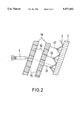
- FIG. 2 is a sectional side elevational view of another preferred embodiment of the invention.
- FIG. 1 there is illustrated a kinetic-energy projectile 1 which flies in the direction of the principal armor 2 of a non-illustrated target (such as a tank).
- a reactive armor 4 In front of the armor 2 a reactive armor 4 is positioned which is formed of a plurality of modules 3 (only six are shown for better visibility).
- an additional armor 6 On that side of the reactive armor 4 which is oriented away from the armor 2, an additional armor 6 is positioned which is at a predetermined distance 5 from the reactive armor 4.
- respective sensor films 7, 8 are arranged which are connected by means of electric conductors 9, 10 with an electronic monitoring device 11, such as a microcontroller.
- the output of the electronic monitoring device 11 is connected with the modules 3 by electric conductors 12 and 13 (for clarity, only two of the modules 3 are shown to be connected with the device 11).
- a supplemental armor plate 14 is provided in front of the additional armor 6. Further, between the additional armor 6 and the reactive armor 4 an embossed sheet metal component 15 is arranged which is designed to interfere with the particle jet of any shaped charge.
- the projectile 1 After penetrating the supplemental armor plate 14, the projectile 1 first contacts the outer sensor foil 7 which generates a corresponding signal from which the electronic monitoring device 11 determines the position (that is, the coordinates relative to a reference point) of the entry of the projectile 1. Upon passing through the additional armor 6, the direction of the projectile 1 is slightly changed and the projectile is initially fragmented and thereafter passes through the inner sensor film 8 which too, produces a signal from which the electronic monitoring device 11 determines the coordinates of the impact position on the film relative to a reference point.
- the electronic monitoring device 11 From the coordinates of the location of passages through the two sensor films 7 and 8 the electronic monitoring device 11 computes the direction of flight of the initially fragmented projectile 1' and selects that module or those modules 3 which should be triggered in order to interfere with the projectile 1' in an optimal manner.
- the triggering signal for the selected module 3 is activated by the electronic monitoring device 11 and is transmitted by corresponding conductors 12, 13 to the electrically ignitable explosive film 16.
- the corresponding armor plate 17 of the module 3 moves, explosively accelerated, towards the initially fragmented projectile 1' and destroys it.
- the individual modules 3 are arranged in a zigzag pattern, that is, at an alternating oblique inclination to the surface of the target to be protected.
- the distance 5 between the additional armor 6 and the reactive armor 4 has to be selected such that a sufficient path is available for "consuming” the projectile 1 by the explosively accelerated armor plate 17 and should be preferably in the magnitude of one-half of the expected length of the projectile penetrator.
- FIG. 2 illustrates a further embodiment of the invention according to which the additional armor 18 is formed of two parallel-spaced armor plates each composed of individual armor plate elements 19.
- the additional armor 18 is formed of two parallel-spaced armor plates each composed of individual armor plate elements 19.
- a shock or acceleration sensor which identifies that armor plate element 19 which has been contacted by the projectile 1. This information is applied to the electronic monitoring device 11 (FIG. 1) which, according to a predetermined schedule, selects and ignites the corresponding module 3 of the reactive armor 4.
- the electronic monitoring device 11 may be connected by means of an electric conductor 20 shown in dash-dotted lines in FIG. 1 with a master system 21 of the target (tank).
- a master system may be, for example, an on-board computer or a weapon control system.
- the electronic monitoring device 11 may, based on the sensed data, compute the projectile velocity and location of launching and inform the system 21 accordingly. In response, the system 21 may aim its weapons against the adversary.
- a catching element 22 is provided as shown in dashed lines in FIGS. 1 and 2. In this manner damages to adjacent modules 3 by projectile fragments or the explosively accelerated armor plates 17 is prevented.
- the catching elements 22 simultaneously serve as mounting components for the outer armor.
Landscapes
- Engineering & Computer Science (AREA)
- General Engineering & Computer Science (AREA)
- Aiming, Guidance, Guns With A Light Source, Armor, Camouflage, And Targets (AREA)
Abstract
Description
Claims (9)
Applications Claiming Priority (2)
| Application Number | Priority Date | Filing Date | Title |
|---|---|---|---|
| DE4440120.5 | 1994-11-10 | ||
| DE4440120A DE4440120C2 (en) | 1994-11-10 | 1994-11-10 | Protective device with reactive armor |
Publications (1)
| Publication Number | Publication Date |
|---|---|
| US5577432A true US5577432A (en) | 1996-11-26 |
Family
ID=6532944
Family Applications (1)
| Application Number | Title | Priority Date | Filing Date |
|---|---|---|---|
| US08/554,167 Expired - Fee Related US5577432A (en) | 1994-11-10 | 1995-11-06 | Protective device having a reactive armor |
Country Status (5)
| Country | Link |
|---|---|
| US (1) | US5577432A (en) |
| CH (1) | CH691408A5 (en) |
| DE (1) | DE4440120C2 (en) |
| FR (1) | FR2726899B1 (en) |
| GB (1) | GB2295003B (en) |
Cited By (26)
| Publication number | Priority date | Publication date | Assignee | Title |
|---|---|---|---|---|
| JP2001002000A (en) * | 1999-06-21 | 2001-01-09 | Tech Res & Dev Inst Of Japan Def Agency | Protection structure |
| JP2002295996A (en) * | 2001-03-30 | 2002-10-09 | Mitsubishi Heavy Ind Ltd | Defending device against missile |
| WO2002086410A1 (en) * | 2001-04-21 | 2002-10-31 | Diehl Munitionssysteme Gmbh & Co. Kg. | Reactive armor module |
| US6474213B1 (en) | 2000-08-09 | 2002-11-05 | Southwest Research Institute | Reactive stiffening armor system |
| US6622608B1 (en) * | 2001-06-26 | 2003-09-23 | United Defense Lp | Variable standoff extendable armor |
| US6662726B1 (en) | 1999-03-08 | 2003-12-16 | General Dynamics Ordnance And Tactical Systems, Inc. | Kinetic energy penetrator |
| EP1635133A2 (en) | 2004-09-10 | 2006-03-15 | VOP-026 Sternberk, s.p. | Hardkill active protection countermeasure |
| US20080017426A1 (en) * | 2006-03-23 | 2008-01-24 | Walters Raul J | Modular vehicle system and method |
| US20090050041A1 (en) * | 2007-05-15 | 2009-02-26 | Geke Technologie Gmbh | Watercraft with a protective device against shaped/hollow charges |
| US20090114083A1 (en) * | 2006-01-23 | 2009-05-07 | Moore Iii Dan T | Encapsulated ceramic composite armor |
| US20090151549A1 (en) * | 2007-12-18 | 2009-06-18 | Saab Ab | Electricity generating device for use in an armour arrangement, and an armour arrangement of this kind |
| WO2011005275A1 (en) * | 2009-07-09 | 2011-01-13 | Lockheed Marting Corporation | Armor having prismatic, tesselated core |
| US20120174759A1 (en) * | 2008-08-19 | 2012-07-12 | Gallo Michael J | Encapsulated ballistic protection system |
| US20130087038A1 (en) * | 2011-10-06 | 2013-04-11 | General Dynamics Armament And Technical Products, Inc. | Capacitive reactive armor assembly |
| US20130213210A1 (en) * | 2010-08-13 | 2013-08-22 | Geke Schutztechnik Gmbh | Reactive protection arrangement |
| US20130239835A1 (en) * | 2012-03-19 | 2013-09-19 | The Boeing Company | Method and system for electronically shaping detonated charges |
| US8850946B2 (en) | 2009-07-09 | 2014-10-07 | Lockheed Martin Corporation | Armor having prismatic, tesselated core |
| US8985001B2 (en) | 2008-07-22 | 2015-03-24 | Lockheed Martin Corporation | Armor having prismatic, tesselated core |
| WO2010082970A3 (en) * | 2008-10-23 | 2016-03-31 | University Of Virginia Patent Foundation | Reactive topologically controlled armors for protection and related method |
| US20160273885A1 (en) * | 2015-03-20 | 2016-09-22 | The Boeing Company | System, method, and assembly for adaptively shielding a structure |
| US9797691B1 (en) | 2014-11-03 | 2017-10-24 | Lockheed Martin Corporation | Ceramic armor buffers for enhanced ballistic performance |
| US9885543B2 (en) | 2015-10-01 | 2018-02-06 | The United States Of America As Represented By The Secretary Of The Army | Mechanically-adaptive, armor link/linkage (MAAL) |
| US20180299229A1 (en) * | 2015-10-22 | 2018-10-18 | David Cohen | Reactive armor |
| US10670375B1 (en) | 2017-08-14 | 2020-06-02 | The United States Of America As Represented By The Secretary Of The Army | Adaptive armor system with variable-angle suspended armor elements |
| EP3707459A4 (en) * | 2017-11-09 | 2021-10-13 | David Cohen | Reactive armor |
| EP4345409A1 (en) | 2022-09-30 | 2024-04-03 | John Cockerill Defense SA | Unmanned turret having a ballistic protection system in the roof structure and in the floor |
Families Citing this family (8)
| Publication number | Priority date | Publication date | Assignee | Title |
|---|---|---|---|---|
| DE19754936A1 (en) | 1997-12-10 | 1999-07-01 | Wegmann & Co Gmbh | Sealing and guiding device for highly dynamically accelerated, distance-effective protective elements |
| US7859566B2 (en) | 2004-01-20 | 2010-12-28 | Rheinmetall Landsysteme Gmbh | Arrangement of a first and at least a second additional vehicle in a loosely couplable not track bound train |
| DE102004003055A1 (en) * | 2004-01-20 | 2005-08-18 | Rheinmetall Landsysteme Gmbh | Arrangement of a first and at least one other vehicle in a loosely coupled non-track-bound train |
| KR100636827B1 (en) | 2004-10-18 | 2006-10-20 | 국방과학연구소 | Explosive reactive armor with momentum transfer mechanism |
| EA200601154A1 (en) * | 2006-06-14 | 2007-04-27 | Василий Николаевич Тикменов | ACTIVE ARRAY |
| EP2056060A1 (en) * | 2007-11-02 | 2009-05-06 | Saab AB | Electricity generating device for use in an armour arrangement, and an armour arrangement of this kind |
| IL239523A0 (en) * | 2015-02-26 | 2015-11-30 | Cohen David | Armor |
| FR3136843A1 (en) | 2022-06-17 | 2023-12-22 | Nexter Munitions | Threat detection system and method for reactive armor, and associated reactive protection system |
Citations (8)
| Publication number | Priority date | Publication date | Assignee | Title |
|---|---|---|---|---|
| US3893368A (en) * | 1954-12-01 | 1975-07-08 | Us Army | Device for the protection of targets against projectiles |
| DE978036C (en) * | 1976-04-22 | Messerschmitt-Bölkow-Blohm GmbH, 8000 München | Protection device for stationary or moving targets against destruction by projectiles or similar weapons | |
| US4051763A (en) * | 1964-12-11 | 1977-10-04 | Messerschmitt-Bolkow-Blohm Gesellschaft Mit Beschrankter Haftung | Armament system and explosive charge construction therefor |
| DE2611163A1 (en) * | 1976-03-17 | 1977-10-06 | Alfred Linshoeft | Antimissile system for armoured vehicles - has electrically ignited explosive charges to destroy or deflect approaching missile by gas press. and mine effect |
| US4752970A (en) * | 1987-06-16 | 1988-06-28 | Arakaki Steven Y | Protective face shield |
| GB2234334A (en) * | 1980-03-07 | 1991-01-30 | Helmut Nussbaum | Active protective element |
| JPH0367999A (en) * | 1989-08-07 | 1991-03-22 | Mitsubishi Heavy Ind Ltd | Reactive armoring plate |
| DE4122622A1 (en) * | 1991-07-09 | 1993-01-28 | Diehl Gmbh & Co | Missile detector for active protection device - senses approach of missile and ejects armoured plate out towards missile |
Family Cites Families (3)
| Publication number | Priority date | Publication date | Assignee | Title |
|---|---|---|---|---|
| DE2719150C1 (en) * | 1977-04-29 | 1987-03-05 | Industrieanlagen Betriebsges | Protection device against high energy projectiles |
| DE2906378C1 (en) * | 1979-02-20 | 1990-11-15 | Helmut Dipl-Phys Nussbaum | Active protection device for fixed or moving objects |
| IL88986A (en) * | 1989-01-18 | 1994-06-24 | Ministry Of Defence Rafael Arm | Combined reactive and passive armour |
-
1994
- 1994-11-10 DE DE4440120A patent/DE4440120C2/en not_active Expired - Fee Related
-
1995
- 1995-10-17 CH CH02943/95A patent/CH691408A5/en not_active IP Right Cessation
- 1995-11-02 FR FR9512921A patent/FR2726899B1/en not_active Expired - Fee Related
- 1995-11-06 US US08/554,167 patent/US5577432A/en not_active Expired - Fee Related
- 1995-11-10 GB GB9523084A patent/GB2295003B/en not_active Expired - Fee Related
Patent Citations (8)
| Publication number | Priority date | Publication date | Assignee | Title |
|---|---|---|---|---|
| DE978036C (en) * | 1976-04-22 | Messerschmitt-Bölkow-Blohm GmbH, 8000 München | Protection device for stationary or moving targets against destruction by projectiles or similar weapons | |
| US3893368A (en) * | 1954-12-01 | 1975-07-08 | Us Army | Device for the protection of targets against projectiles |
| US4051763A (en) * | 1964-12-11 | 1977-10-04 | Messerschmitt-Bolkow-Blohm Gesellschaft Mit Beschrankter Haftung | Armament system and explosive charge construction therefor |
| DE2611163A1 (en) * | 1976-03-17 | 1977-10-06 | Alfred Linshoeft | Antimissile system for armoured vehicles - has electrically ignited explosive charges to destroy or deflect approaching missile by gas press. and mine effect |
| GB2234334A (en) * | 1980-03-07 | 1991-01-30 | Helmut Nussbaum | Active protective element |
| US4752970A (en) * | 1987-06-16 | 1988-06-28 | Arakaki Steven Y | Protective face shield |
| JPH0367999A (en) * | 1989-08-07 | 1991-03-22 | Mitsubishi Heavy Ind Ltd | Reactive armoring plate |
| DE4122622A1 (en) * | 1991-07-09 | 1993-01-28 | Diehl Gmbh & Co | Missile detector for active protection device - senses approach of missile and ejects armoured plate out towards missile |
Cited By (43)
| Publication number | Priority date | Publication date | Assignee | Title |
|---|---|---|---|---|
| US6662726B1 (en) | 1999-03-08 | 2003-12-16 | General Dynamics Ordnance And Tactical Systems, Inc. | Kinetic energy penetrator |
| JP2001002000A (en) * | 1999-06-21 | 2001-01-09 | Tech Res & Dev Inst Of Japan Def Agency | Protection structure |
| US6474213B1 (en) | 2000-08-09 | 2002-11-05 | Southwest Research Institute | Reactive stiffening armor system |
| JP2002295996A (en) * | 2001-03-30 | 2002-10-09 | Mitsubishi Heavy Ind Ltd | Defending device against missile |
| WO2002086410A1 (en) * | 2001-04-21 | 2002-10-31 | Diehl Munitionssysteme Gmbh & Co. Kg. | Reactive armor module |
| US6622608B1 (en) * | 2001-06-26 | 2003-09-23 | United Defense Lp | Variable standoff extendable armor |
| EP1635133A2 (en) | 2004-09-10 | 2006-03-15 | VOP-026 Sternberk, s.p. | Hardkill active protection countermeasure |
| US7866248B2 (en) | 2006-01-23 | 2011-01-11 | Intellectual Property Holdings, Llc | Encapsulated ceramic composite armor |
| US20090114083A1 (en) * | 2006-01-23 | 2009-05-07 | Moore Iii Dan T | Encapsulated ceramic composite armor |
| US20080017426A1 (en) * | 2006-03-23 | 2008-01-24 | Walters Raul J | Modular vehicle system and method |
| US20090050041A1 (en) * | 2007-05-15 | 2009-02-26 | Geke Technologie Gmbh | Watercraft with a protective device against shaped/hollow charges |
| US20090151549A1 (en) * | 2007-12-18 | 2009-06-18 | Saab Ab | Electricity generating device for use in an armour arrangement, and an armour arrangement of this kind |
| US7658139B2 (en) * | 2007-12-18 | 2010-02-09 | Saab Ab | Electricity generating device for use in an armour arrangement, and an armour arrangement of this kind |
| US9188410B2 (en) | 2008-07-22 | 2015-11-17 | Lockheed Martin Corporation | Armor having prismatic, tesselated core |
| US9182200B2 (en) | 2008-07-22 | 2015-11-10 | Lockheed Martin Corporation | Armor having prismatic, tesselated core |
| US8985001B2 (en) | 2008-07-22 | 2015-03-24 | Lockheed Martin Corporation | Armor having prismatic, tesselated core |
| US20120174759A1 (en) * | 2008-08-19 | 2012-07-12 | Gallo Michael J | Encapsulated ballistic protection system |
| US8616113B2 (en) * | 2008-08-19 | 2013-12-31 | Kelly Space & Technology, Inc. | Encapsulated ballistic protection system |
| WO2010082970A3 (en) * | 2008-10-23 | 2016-03-31 | University Of Virginia Patent Foundation | Reactive topologically controlled armors for protection and related method |
| WO2011005275A1 (en) * | 2009-07-09 | 2011-01-13 | Lockheed Marting Corporation | Armor having prismatic, tesselated core |
| US8850946B2 (en) | 2009-07-09 | 2014-10-07 | Lockheed Martin Corporation | Armor having prismatic, tesselated core |
| US20130213210A1 (en) * | 2010-08-13 | 2013-08-22 | Geke Schutztechnik Gmbh | Reactive protection arrangement |
| US9032858B2 (en) * | 2010-08-13 | 2015-05-19 | Geke Schutztechnik Gmbh | Reactive protection arrangement |
| US8807009B2 (en) * | 2011-10-06 | 2014-08-19 | General Dynamics—OTS, Inc. | Capacitive reactive armor assembly |
| US20130087038A1 (en) * | 2011-10-06 | 2013-04-11 | General Dynamics Armament And Technical Products, Inc. | Capacitive reactive armor assembly |
| US20150300787A1 (en) * | 2012-03-19 | 2015-10-22 | The Boeing Company | Method and System for Electronically Shaping Detonated Charges |
| JP2013195058A (en) * | 2012-03-19 | 2013-09-30 | Boeing Co:The | Mechanism for electronically shaping detonated charge |
| US20130239835A1 (en) * | 2012-03-19 | 2013-09-19 | The Boeing Company | Method and system for electronically shaping detonated charges |
| US9291434B2 (en) * | 2012-03-19 | 2016-03-22 | The Boeing Company | Method and system for electronically shaping detonated charges |
| US8863666B2 (en) * | 2012-03-19 | 2014-10-21 | The Boeing Company | Method and system for electronically shaping detonated charges |
| US9797691B1 (en) | 2014-11-03 | 2017-10-24 | Lockheed Martin Corporation | Ceramic armor buffers for enhanced ballistic performance |
| US10215535B2 (en) * | 2015-03-20 | 2019-02-26 | The Boeing Company | System, method, and assembly for adaptively shielding a structure |
| US20160273885A1 (en) * | 2015-03-20 | 2016-09-22 | The Boeing Company | System, method, and assembly for adaptively shielding a structure |
| US9885543B2 (en) | 2015-10-01 | 2018-02-06 | The United States Of America As Represented By The Secretary Of The Army | Mechanically-adaptive, armor link/linkage (MAAL) |
| JP2018531363A (en) * | 2015-10-22 | 2018-10-25 | ダビデ、コーエンDavid Cohen | Reactive armor |
| US20180299229A1 (en) * | 2015-10-22 | 2018-10-18 | David Cohen | Reactive armor |
| EP3365628A4 (en) * | 2015-10-22 | 2019-09-11 | David Cohen | Reactive armor |
| JP2021181881A (en) * | 2015-10-22 | 2021-11-25 | ダビデ、コーエンDavid Cohen | Reactivity armor |
| US10670375B1 (en) | 2017-08-14 | 2020-06-02 | The United States Of America As Represented By The Secretary Of The Army | Adaptive armor system with variable-angle suspended armor elements |
| EP3707459A4 (en) * | 2017-11-09 | 2021-10-13 | David Cohen | Reactive armor |
| US11512930B2 (en) | 2017-11-09 | 2022-11-29 | David Cohen | Reactive armor |
| EP4345409A1 (en) | 2022-09-30 | 2024-04-03 | John Cockerill Defense SA | Unmanned turret having a ballistic protection system in the roof structure and in the floor |
| WO2024068117A1 (en) | 2022-09-30 | 2024-04-04 | John Cockerill Defense SA | Unmanned turret having a ballistic protection system in the roof structure and in the floor |
Also Published As
| Publication number | Publication date |
|---|---|
| CH691408A5 (en) | 2001-07-13 |
| GB9523084D0 (en) | 1996-01-10 |
| GB2295003B (en) | 1998-04-15 |
| DE4440120C2 (en) | 1998-03-19 |
| DE4440120A1 (en) | 1996-05-15 |
| GB2295003A (en) | 1996-05-15 |
| FR2726899A1 (en) | 1996-05-15 |
| FR2726899B1 (en) | 1997-06-27 |
Similar Documents
| Publication | Publication Date | Title |
|---|---|---|
| US5577432A (en) | Protective device having a reactive armor | |
| CA2554839C (en) | Active protection device and associated apparatus, system, and method | |
| US7104496B2 (en) | Active protection device and associated apparatus, system, and method | |
| US5070764A (en) | Combined reactive and passive armor | |
| US6327955B1 (en) | Active protection device for the wall of a vehicle or a structure | |
| US5400688A (en) | Missile defense system | |
| US5625160A (en) | Protection arrangement for affording protection from an approaching projectile | |
| WO2011148165A1 (en) | Device for mitigating the effects of explosive events | |
| US6782790B2 (en) | Method for deflecting fast projectiles | |
| GB2306208A (en) | Armoured vehicle protection | |
| WO2007089253A2 (en) | Method and apparatus for protecting vehicles and personnel against incoming projectiles | |
| US7387060B1 (en) | Rocket exhaust defense system and method | |
| US20070221052A1 (en) | Very lightweight reactive applique armor | |
| US9291434B2 (en) | Method and system for electronically shaping detonated charges | |
| EP2338022B1 (en) | Enclosure protecting system and method | |
| GB2392487A (en) | Protection against fast projectiles | |
| US6244156B1 (en) | Method of protecting an object from the effect of a high-speed projectile | |
| US9891027B2 (en) | System and method for neutralizing shaped-charge threats | |
| GB2329233A (en) | Reactive ballistic protection device | |
| EP0199447A2 (en) | Apparatus for the detection and destruction of incoming objects | |
| IL176947A (en) | Reactive armour | |
| Sleiman et al. | Requirements Comparison Hit-to—Kill VS Warhead for TMD | |
| SE468331B (en) | Method of, with a liquid-bearing projectile, spreading liquid on a surface and projectile for implementing the method |
Legal Events
| Date | Code | Title | Description |
|---|---|---|---|
| AS | Assignment |
Owner name: RHEINMETAL INDUSTRIE GMBH, GERMANY Free format text: ASSIGNMENT OF ASSIGNOR'S INTEREST (RE-RECORD TO CORRECT RECORDAL DATE OF 2-15-1996 ON A PREVIOUSLY RECORDED DOCUMENT AT REEL 7816, FRAME 0645. RECORDAL DATE SHOULD HAVE BEEN 2-5-1996).;ASSIGNORS:BECKER, WILFRIED;SCHOLLES, HERBERT;KILFITT, DIRK;REEL/FRAME:008065/0314;SIGNING DATES FROM 19951117 TO 19951122 |
|
| AS | Assignment |
Owner name: RHEINMETALL INDUSTRIE GMBH, GERMANY Free format text: ASSIGNMENT OF ASSIGNORS INTEREST;ASSIGNORS:BECKER, WILFRIED;SCHOLLES, HERBERT;KILFITT, DIRK;REEL/FRAME:007816/0645;SIGNING DATES FROM 19951117 TO 19951122 |
|
| AS | Assignment |
Owner name: RHEINMETALL INDUSTRIE AKTIENGESELLSCHAFT, GERMANY Free format text: GERMAN LANGUAGE COMMERICAL REGISTER EXTRACT WITH TRANSLATION;ASSIGNOR:RHEINMETALL INDUSTRIE GMBH;REEL/FRAME:008191/0785 Effective date: 19960610 |
|
| FEPP | Fee payment procedure |
Free format text: PAYOR NUMBER ASSIGNED (ORIGINAL EVENT CODE: ASPN); ENTITY STATUS OF PATENT OWNER: LARGE ENTITY |
|
| FPAY | Fee payment |
Year of fee payment: 4 |
|
| FPAY | Fee payment |
Year of fee payment: 8 |
|
| REMI | Maintenance fee reminder mailed | ||
| LAPS | Lapse for failure to pay maintenance fees | ||
| STCH | Information on status: patent discontinuation |
Free format text: PATENT EXPIRED DUE TO NONPAYMENT OF MAINTENANCE FEES UNDER 37 CFR 1.362 |
|
| FP | Lapsed due to failure to pay maintenance fee |
Effective date: 20081126 |