US4901195A - Self-proving vehicle grounding system - Google Patents
Self-proving vehicle grounding system Download PDFInfo
- Publication number
- US4901195A US4901195A US07/213,594 US21359488A US4901195A US 4901195 A US4901195 A US 4901195A US 21359488 A US21359488 A US 21359488A US 4901195 A US4901195 A US 4901195A
- Authority
- US
- United States
- Prior art keywords
- coupled
- ground
- overfill protection
- grounding
- electrical
- Prior art date
- Legal status (The legal status is an assumption and is not a legal conclusion. Google has not performed a legal analysis and makes no representation as to the accuracy of the status listed.)
- Expired - Lifetime
Links
Images


Classifications
-
- B—PERFORMING OPERATIONS; TRANSPORTING
- B67—OPENING, CLOSING OR CLEANING BOTTLES, JARS OR SIMILAR CONTAINERS; LIQUID HANDLING
- B67D—DISPENSING, DELIVERING OR TRANSFERRING LIQUIDS, NOT OTHERWISE PROVIDED FOR
- B67D7/00—Apparatus or devices for transferring liquids from bulk storage containers or reservoirs into vehicles or into portable containers, e.g. for retail sale purposes
- B67D7/06—Details or accessories
- B67D7/32—Arrangements of safety or warning devices; Means for preventing unauthorised delivery of liquid
- B67D7/3236—Arrangements of safety or warning devices; Means for preventing unauthorised delivery of liquid relating to electrostatic charges
-
- H—ELECTRICITY
- H02—GENERATION; CONVERSION OR DISTRIBUTION OF ELECTRIC POWER
- H02H—EMERGENCY PROTECTIVE CIRCUIT ARRANGEMENTS
- H02H11/00—Emergency protective circuit arrangements for preventing the switching-on in case an undesired electric working condition might result
- H02H11/001—Emergency protective circuit arrangements for preventing the switching-on in case an undesired electric working condition might result in case of incorrect or interrupted earth connection
Definitions
- the invention relates generally to systems for connecting two o more electrically conductive objects to the same electrical ground potential and proving the connection.
- the invention is particularly adapted to be used for grounding vehicles for transporting highly flammable fluids to the same ground potential as the loading racks from which the fluids are pumped into the vehicles in order to prevent static electric discharges from occurring near the fluid.
- the present invention is intended for use at loading racks where Class I, Division 1, groups A, B, C or D hazardous substances, as defined by the National Electrical Code, Article 500, are loaded into tank trucks for transportation. Most gasoline and petroleum products such as diesel fuel, jet fuel and automobile fuel fall into one of these catagories, as do gases such as acetylene and hydrogen.
- Many filling stations are therefore equipped with a grounding system in order to prevent static electric discharges of this type.
- the simplest systems provide a cable which is electrically connected to the filling station at one end and which has a clamp at the other end that can be connected or clamped to a metal part of the vehicle when in the filling station. If there is a voltage potential difference between the filling station and the vehicle, a static electric discharge will occur at the time and place where the cable contact is made and the filling station and vehicle will thereafter remain at the same ground.
- the point of connection to the vehicle can be made at a location remote from the filling nozzle or any other area where the flammable substance may be, thereby eliminating any risk of igniting the flammable substance.
- the ohmeter circuit is connected to a disabling circuit which disables the filling equipment if the resistance between the jaws exceeds a certain level and enables the equipment when it is below the specified level.
- the resistance between the jaws of the clamp when it is not connected to metal is theoretically infinite, while the resistance when the clamp is connected to a piece of metal and the jaws both contact the metal is theoretically zero. Therefore, when the clamp is connected to the vehicle, the resistance between the jaws will be below the threshold and the filling equipment will be enabled. Unfortunately, this grounding system can be easily defeated by connecting the clamp to any piece of metal whether it is on the vehicle or not.
- Overfill protection circuits typically comprise two separate units.
- the first unit is mounted on the vehicle and comprises sensors within the cargo tank which detect the level of the fluid within the cargo tank and related circuitry for providing the information from the sensors to the second unit.
- the second unit is mounted on the loading rack and comprises circuitry for disabling the pumping equipment when the sensors indicate that the vehicle is fully loaded.
- the use of overfill protection circuitry on the vehicle requires a second electrical cable to be connected between the vehicle and the loading rack in order to couple the sensor circuitry to the base unit circuitry. As in the case of the grounding systems of the prior art, the workers at the loading racks frequently neglect to connect the overfill protection circuitry to the loading rack, thereby defeating this safety feature also.
- the self proving vehicle grounding system of the present invention is intended for use in conjunction with an overfill protection system and comprises three separate parts.
- the main section is termed the controller and is mounted on the loading rack or filling station and connected to its ground.
- the second part is the grounding bolt which is grounded to the chassis of the vehicle which it is desired to ground to the filling station.
- the overfill protection sensor circuitry is also grounded to the chassis.
- the third part comprises a multi-conductor cable which provides the necessary connections between the first and second parts of the grounding system as well as the first and second parts of an overfill protection system.
- the controller section is equipped with a cable which is to be connected to the grounding bolt of a vehicle which is in the filling station.
- the electrical cable is a multi conductor cable providing a SIGNAL line from the controller to the grounding bolt, a GROUND line and all signal paths necessary for the overfill protection system.
- the controller section comprises in part a signal generator and a relay. Connected in the grounding bolt, between the terminal for the SIGNAL line and the terminal for the GROUND line, is certain circuitry which, when connected to the cable from the controller becomes part of the signal generator circuitry. When the circuitry contained in the grounding bolt is not made part of the signal generator circuity, the signal generator circuitry produces a signal which turns the relay off.
- the relay allows the filling station equipment to operate only when the relay is on. Therefore, when the cable from the control unit is hooked up to anything but the grounding bolt, the relay will be turned off thereby disabling filling station equipment.
- grounding bolt and the overfill protection sensor circuitry of the vehicle are electrically coupled to the ground controller and overfill protection base unit associated with the loading rack, respectively, by a single multi-conductor cable connector thereby requiring a single cable hookup to enable both systems.
- the controller is equipped with an alternative cable connector.
- the alternative connector simply provides, within the controller itself the same circuitry that is in the grounding bolt and affords a non-self-proving connection.
- the alternative connector is provided so that vehicles that are not fitted with the grounding bolt of the present invention can nevertheless be filled at a controller equipped filling station.
- the alternative cable connector is also somewhat self-proving in that the SIGNAL and GROUND lines must somehow be electrically connected at the opposite end of the cable in order for the circuit to be completed. Otherwise, the circuitry which completes the signal generator to turn the relay on will remain open circuited and therefore will not affect the remaining signal generator circuitry, in which case the relay remains off.
- FIG. 1 shows a block diagram broadly illustrating the electrical connections of the present invention.
- FIG. 2 shows a block diagram of the controller unit and grounding bolt unit of the present invention.
- FIG. 3 shows a detailed circuit diagram of the controller unit and the grounding bolt unit of the present invention.
- the invention comprises a grounding cable for placing two electrically conductive objects at the same voltage potential and related circuitry fordetermining if the proper connection has been made.
- the invention is particularly adapted to be used at loading racks for transferring highly flammable fluids from stationary tanks to vehicles for transportation.
- FIG. 1 shows a block diagram illustrating the electrical connections made between the loading rack 16 and the vehicle 11.
- the controller 12 of the grounding system of the present invention is connected to the electrical ground of the loading rack at terminal 2 of the terminal strip 13.
- the overfill protection base unit 15 is also connected to the electrical ground of the loading rack as well as being physically attached thereto. Both the grounding system controller 12 and the overfill protection base unit 15 provide power to the pumping equipment via lines 17 and 19, respectively.
- the grounding system controller 12 cuts off power to lines17 unless a proper ground contact is made between the rack 16 and the vehicle 11.
- power to lines 19 is cut off by the overfill protection base unit 15 when overfill protection sensor circuit 21 indicates that the vehicle has reached its cargo capacity.
- a vehicle equipped for operation with the present invention comprises a grounding bolt 14 and overfill protection sensors with related circuitry 21.
- the grounding system controller 12 In order for the grounding system and overfill protection system to operate, the grounding system controller 12 must be properly coupled to the grounding bolt 14 and the overfill protection base unit 15 must be properly connected to the overfill protection circuitry 21 of the vehicle.
- the present invention utilizes the Scully Thermistor Overfill Protection System offered by Scully Electronics, Inc. of Wilmington, Mass. This particular overfill protection system requires amaximum of eight signal paths plus a ground connection between the base unit 15 and the sensor circuitry 21. As will be explained in greater detail herein, the grounding system requires the connection of only one signal path and a ground between the controller 12 and the grounding bolt 14.
- the loading rack 16 and the vehicle 11 are provided with terminal strips 8 and 9, respectively, each having ten terminals, one terminal for the signal path of the grounding system, eight terminals for the signal paths of the overfill protection system and a shared ground line.
- a cable 18 having terminal strips at either end containing ten terminals has one end connected to terminal strip 8 on rack 16.
- the rack operator connects the other end of cable 18 to terminal strip 9 on the vehicle, thereby properly connecting both the grounding system and the overfill protection system with a single cable connection.
- the actual circuitry of the overfill protection system is not of concern to the present invention and will not be discussed in any further detail.
- the ground connection between the rack and the vehicle is made from the rack, out of terminal 9 on strip 8, through cable18, into terminal 9 on strip 9 and into the grounding bolt 14. Further, a SIGNAL line connection is made between the controller 12 and the bolt 14 via terminal 10 on strip 8, through cable 18, to terminal 10 on strip 9, and then into the grounding bolt 14.
- Terminal strip 9 on the vehicle 18 should be located at a place on the vehicle remote from the filling valves and other equipment which will comein contact with the flammable fluid.
- the loading rack and the vehicle are at different potentials and their grounds are connected by cable 18, astatic electric discharge will occur Since, however, terminal strip 9 is located at a place remote from the fluid, the static electric discharge will present no danger.
- Any vehicle having a grounding bolt such as unit 14 can be loaded at a grounding system controller equipped loading rack 16.
- the controller unit is also equipped to operate in a non-self-proving mode so that vehicles that are not equipped with thegrounding bolt 14 can also use the loading rack, if necessary.
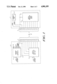
- FIG. 2 shows a block diagram of the circuitry of the grounding system of the present invention.
- the circuitry in the system is designed to disable loading pumps, valves and other equipment unless the proper ground connection is made between the controller unit 12 and the grounding bolt 14. This system is self-proving in that the controller willcut off the electrical power supply to the loading equipment unless cable 8is connected between terminal strips 8 and 9.
- the circuitry of the system consists of five functional blocks as illustrated in FIG. 2.
- the first block 22 is the power supply section.
- the invention is designed to be powered by a normal 115V or 230V alternating current power supply as is typically found in most industrialized nations.
- Block 22 converts the incoming line voltage (either 115V AC or 130V AC) to 30V AC.
- the system is designed for use with Class I, Div. 1, Groups A, B, C, and Dhazardous substances as defined in the National Electrical Code, Article 500.
- Class I Div. 1
- Groups A, B, C and Dhazardous substances as defined in the National Electrical Code, Article 500.
- 30V AC in conjunction withappropriate current limiting circuit design is defined as being intrinsically safe for use with materials in the above mentioned classifications since it is considered to be incapable of causing the ignition of such materials.
- Block 24 the second block, comprises a signal generator which supplies a specified signal at its output 25.
- the electrical ground 18B of the controller unit 12 will be connected to the electrical ground 26B of the grounding bolt unit 14. Additionally, SIGNAL line 18A of the controller 12will be connected to line 26A of the grounding bolt.
- the third block of thesystem is the signal modifier 28 which is contained within the grounding bolt 14. When cable 18 is connected to terminal strip 9, the signal modifier 28 alters the signal generator signal as it appears at the input 31 of the fourth block in FIG. 2.
- the fourth block of the circuit is the signal detector 30 which is contained within the controller unit 12.
- the signal detector 30 examines the signal which it receives at its input 31 and energizes the fifth block, the high isolation relay 32, only when it detects the modified signal which is the result of the coupling of the signal generator 24 and the signal modifier 28 via cable 18.
- the high isolation relay block 32 which is contained within the controller 12 interrupts the line power of the pumping equipment such that no power reaches the pumping equipment unless the relay is energized. If the signaldetector receives an unmodified signal from signal generator 24, or any signal which is modified by anything but the signal modifier 28 in the grounding bolt 14, it will not energize the high isolation relay 32.
- the relay 32 is provided with several form C dry contacts which are actuated when the relay is energized.
- the pumping equipment is connected to receive its power supply through these contacts.
- the relay is connected to turn on light 36, which is mounted on the enclosure containing the controller unit 12, when the relay is energized and light 38 when the relay is not energized.
- the lights 36 and 38 are green and red, respectively.
- the signal detector 28 will receive only the signal generated by signal generator 24. If lines 18A and 18B of cable 18 are somehow connected to close the circuit between18A and 18B without using the grounding bolt 14, the signal received by signal detector 30 may be modified but not to the proper form for energizing relay 32.
- FIG. 3 shows a detailed schematic of the preferred circuitry for the controller unit 12 and the grounding bolt unit 14.
- the controller unit 12 contains a bracket at one end of the enclosure which provides a terminal strip 39 with nine terminals.
- Connectors 1,2 and 3 are for 115V or 230V ACpower input and the connectors 4-9 for the pumping equipment power supply which are coupled to the dry control contacts 34 of the relay circuit.
- Wiring to the red and green lamps on the enclosure of the control unit enter the unit on a second terminal strip 41.
- a third terminal strip 13 provides the SIGNAL line and GROUND line connections to cable 18.
- the grounding bolt unit 14 contains a terminal strip having two connections, the first connector 26A couples the SIGNAL line 18A to the input of the grounding bolt circuitry, while the second connector 26B couples GROUND line 18B to the ground of the grounding bolt unit 14.
- these connections as well as the connections necessary for the operation of the overfill protection system, are carried from the rack16, out of terminal strip 8, through cable 18, into terminal strip 9 on vehicle 11 and therefrom into the grounding bolt 14 and overfill protection sensor circuity 21.
- a step-down transformer 44 steps the 115V or 230V AC input down to 30V peak AC.
- the transformer also contains a one-time thermal fuse thatwill open if the transformer overheats.
- the transformer's secondary voltagewinding (i.e. 30 volt side) is half waved rectified and filtered by diode D5, capacitor C4 and capacitor C5 to provide power to the operational amplifier 46, and relay 32.
- a voltage divider and filter, made up of resistors R2 and R3, and capacitor C6, provides a 7 volt reference voltageto the inverting input cf the operational amplifier 46.
- the output of the operational amplifier 46 drives the base of transistor Q1 through a current limiting resistor R6.
- Resistor R7 bleeds off residual base voltageon transistor Q1 when the output of the amplifier is low.
- Transistor Q1 is configured as a common emitter saturated switch that drives relay 32.
- Diode D3 protects the collector emitter junction of transistor Q1 from transients generated in the coil of relay 32 when the relay is turned off.
- resistors R2 and R3, and capacitor C6 provide a 7 volt reference voltage at the inverting input of the operational amplifier 46, the outputof operational amplifier 46 will change states (i.e. negative to positive) when the voltage at the non-inverting input crosses the 7 volt threshold.
- Resistors R4 and R5 comprise a voltage divider that defines the threshold voltage that is required to be placed on capacitor C3 to provide the 7 volt threshold level at the non-inverting input. The voltage at the non-inverting input is equal to the voltage across R5. Choosing R4 as 68K ohms and R5 as 12K ohms, this threshold voltage across C3 is set at 46.6 volts. This threshold was selected to be higher than any voltage that is present at the secondary coil of the transformer to guard against a component failure that can cause the system to fail unsafe.
- a charge pumping circuit is used to obtain the 46.6 volts across capacitor C3 that causes the system to operate.
- This charge pump is made up of a non-polar capacitor configuration comprising diodes D1 and D2, capacitors C1 and C2 and diode D7 Diode D7 is not contained within the controller 12 as is the other circuitry, but is in the grounding bolt. It completes the charge pumping circuit when the cable 18 is connected between terminal strips 8 and 9.
- the charge pumping circuit charges capacitor C3 on positive half cycles of the transformer secondary coil voltage and diode D7 in the grounding bolt charges capacitor C3 on negative half cycles.
- Thevoltage that charges C3 during the second (and subsequent) positive half cycles is 30 volts from the secondary coil of the transformer plus the approximately 30 volts of charge from the non-polar capacitor configuration of the charge pumping circuit.
- Capacitor C3 therefore, becomes charged with approximately 60 volts when diode D7 is included in the circuit. Since 60 volts exceeds the 46.6 volt threshold voltage on capacitor C3, this causes the operational amplifier 46 to drive a positivecurrent at its output thereby driving transistor Q1 to energize relay 32. If the grounding bolt is removed from the circuit, the charge pump will nolonger operate and the charge on capacitor C3 will be discharge by resistors R4 and R5 to approximately 30 volts. Since this voltage is less than the threshold voltage of 46.6, volts, the output of the operational amplifier will change state and the relay 32 will no longer be energized.
- Resistor R1 is included in the charge pumping circuit to limit the maximum current that is available at the output line 18A to intrinsically safe levels for Class I, Division 1, Groups A, B, C and D of the National Electrical Code.
Landscapes
- Engineering & Computer Science (AREA)
- Mechanical Engineering (AREA)
- Emergency Protection Circuit Devices (AREA)
Abstract
Description
Claims (12)
Priority Applications (1)
| Application Number | Priority Date | Filing Date | Title |
|---|---|---|---|
| US07/213,594 US4901195A (en) | 1988-06-30 | 1988-06-30 | Self-proving vehicle grounding system |
Applications Claiming Priority (1)
| Application Number | Priority Date | Filing Date | Title |
|---|---|---|---|
| US07/213,594 US4901195A (en) | 1988-06-30 | 1988-06-30 | Self-proving vehicle grounding system |
Publications (1)
| Publication Number | Publication Date |
|---|---|
| US4901195A true US4901195A (en) | 1990-02-13 |
Family
ID=22795709
Family Applications (1)
| Application Number | Title | Priority Date | Filing Date |
|---|---|---|---|
| US07/213,594 Expired - Lifetime US4901195A (en) | 1988-06-30 | 1988-06-30 | Self-proving vehicle grounding system |
Country Status (1)
| Country | Link |
|---|---|
| US (1) | US4901195A (en) |
Cited By (18)
| Publication number | Priority date | Publication date | Assignee | Title |
|---|---|---|---|---|
| US5034726A (en) * | 1990-03-06 | 1991-07-23 | Valvoline Oil & Chemicals Limited | Portable ground fault detector |
| US5159523A (en) * | 1990-10-24 | 1992-10-27 | Cornerstone Fuels, Inc. | Grounding system and detection circuit for fueling |
| US5507326A (en) * | 1994-08-05 | 1996-04-16 | Scully Signal Company | Fluid overfill protection and product identification system |
| US5534856A (en) * | 1993-11-18 | 1996-07-09 | Scully Signal Company | Vehicle identification and verification system |
| EP0748762A2 (en) * | 1995-06-12 | 1996-12-18 | Scully Signal Company | Fail-safe fluid transfer controller |
| FR2772997A1 (en) * | 1997-12-19 | 1999-06-25 | Lefebure | Electrical earth connector grips |
| US5950954A (en) * | 1997-05-21 | 1999-09-14 | Bierer; Walter S | Low impedance device and method of wrapping stored electric cable to minimize its electrical impedance |
| US6127934A (en) * | 1997-04-08 | 2000-10-03 | Aplc, Inc. | Truck grounding system |
| ES2152829A1 (en) * | 1998-06-30 | 2001-02-01 | Maimo Martin Mas | Device for controlling the electrostatic charge during the inter-bin transfer that contain inflammable liquids |
| US6538261B1 (en) | 2000-10-27 | 2003-03-25 | Delaware Capital Formation, Inc. | Wet line fluid removal system with optical sensor |
| US20030164770A1 (en) * | 2000-07-29 | 2003-09-04 | Edge Ian James | Electrical resistance monitoring device |
| US20060186146A1 (en) * | 2005-02-24 | 2006-08-24 | Honda Motor Co., Ltd. | Fuel charging structure of vehicle |
| US20060215346A1 (en) * | 2005-03-25 | 2006-09-28 | Hsin-Ming Yang | Fuel-discharge protection system for preventing electrostatic hazard |
| US8476913B2 (en) | 2007-05-17 | 2013-07-02 | Newson Gale Limited | Improvements relating to the testing of an earth connection |
| US20160154410A1 (en) * | 2013-08-16 | 2016-06-02 | Newson Gale Limited | Monitoring system and method |
| WO2018080448A1 (en) * | 2016-10-25 | 2018-05-03 | Ford Motor Company | Methods and apparatus to ensure grounding between vehicles during vehicle-to-vehicle refueling operations |
| WO2018080449A1 (en) * | 2016-10-25 | 2018-05-03 | Ford Motor Company | Methods and apparatus to ensure grounding between vehicles during vehicle-to-vehicle refueling operations |
| US20180299492A1 (en) * | 2015-08-19 | 2018-10-18 | Siemens Aktiengesellschaft | Self-powered measuring apparatus and measurement method |
Citations (3)
| Publication number | Priority date | Publication date | Assignee | Title |
|---|---|---|---|---|
| US3343154A (en) * | 1964-12-16 | 1967-09-19 | Lockheed Aircraft Corp | Ground indicator |
| US4225899A (en) * | 1979-01-08 | 1980-09-30 | George Sotiriou | Ground detecting device |
| US4691198A (en) * | 1983-12-16 | 1987-09-01 | Alf Mortensen | Control system for diverting/equalizing electrical potentials between two objects |
-
1988
- 1988-06-30 US US07/213,594 patent/US4901195A/en not_active Expired - Lifetime
Patent Citations (3)
| Publication number | Priority date | Publication date | Assignee | Title |
|---|---|---|---|---|
| US3343154A (en) * | 1964-12-16 | 1967-09-19 | Lockheed Aircraft Corp | Ground indicator |
| US4225899A (en) * | 1979-01-08 | 1980-09-30 | George Sotiriou | Ground detecting device |
| US4691198A (en) * | 1983-12-16 | 1987-09-01 | Alf Mortensen | Control system for diverting/equalizing electrical potentials between two objects |
Non-Patent Citations (4)
| Title |
|---|
| Product Literature for the Scully Groundhog Self Proving Vehicle Grounding System, Scully Electronic Systems, 70 Industrial Way, Wilmington, Mass. 01887, May 1987. * |
| Product Literature for the Scully Groundhog Self-Proving Vehicle Grounding System, Scully Electronic Systems, 70 Industrial Way, Wilmington, Mass. 01887, May 1987. |
| Technical description, Scully Groundhog Self Proving Vehicle Grounding System, Scully Electronic System, 70 Industrial Way, Wilmington, Mass. 01887, Mar. 1988. * |
| Technical description, Scully Groundhog Self-Proving Vehicle Grounding System, Scully Electronic System, 70 Industrial Way, Wilmington, Mass. 01887, Mar. 1988. |
Cited By (37)
| Publication number | Priority date | Publication date | Assignee | Title |
|---|---|---|---|---|
| US5034726A (en) * | 1990-03-06 | 1991-07-23 | Valvoline Oil & Chemicals Limited | Portable ground fault detector |
| US5159523A (en) * | 1990-10-24 | 1992-10-27 | Cornerstone Fuels, Inc. | Grounding system and detection circuit for fueling |
| US5534856A (en) * | 1993-11-18 | 1996-07-09 | Scully Signal Company | Vehicle identification and verification system |
| US5507326A (en) * | 1994-08-05 | 1996-04-16 | Scully Signal Company | Fluid overfill protection and product identification system |
| EP0933329A2 (en) * | 1995-06-12 | 1999-08-04 | Scully Signal Company | Fail-safe fluid transfer control |
| EP0748762A3 (en) * | 1995-06-12 | 1997-01-29 | Scully Signal Co | |
| US5771178A (en) * | 1995-06-12 | 1998-06-23 | Scully Signal Company | Fail-safe fluid transfer controller |
| EP0748762A2 (en) * | 1995-06-12 | 1996-12-18 | Scully Signal Company | Fail-safe fluid transfer controller |
| EP0933329A3 (en) * | 1995-06-12 | 1999-08-11 | Scully Signal Company | Fail-safe fluid transfer control |
| EP0933327A3 (en) * | 1995-06-12 | 1999-08-11 | Scully Signal Company | Fluid transfer control method and apparatus |
| EP0933328A3 (en) * | 1995-06-12 | 1999-08-11 | Scully Signal Company | Apparatus and method for controlling the transfer of fluid |
| US5966311A (en) * | 1995-06-12 | 1999-10-12 | Scully Signal Company | Method of overfill probe identification and control |
| US6127934A (en) * | 1997-04-08 | 2000-10-03 | Aplc, Inc. | Truck grounding system |
| US5950954A (en) * | 1997-05-21 | 1999-09-14 | Bierer; Walter S | Low impedance device and method of wrapping stored electric cable to minimize its electrical impedance |
| FR2772997A1 (en) * | 1997-12-19 | 1999-06-25 | Lefebure | Electrical earth connector grips |
| ES2152829A1 (en) * | 1998-06-30 | 2001-02-01 | Maimo Martin Mas | Device for controlling the electrostatic charge during the inter-bin transfer that contain inflammable liquids |
| US6924740B2 (en) * | 2000-07-29 | 2005-08-02 | Newson Gale Limited | Electrical resistance monitoring device |
| US20030164770A1 (en) * | 2000-07-29 | 2003-09-04 | Edge Ian James | Electrical resistance monitoring device |
| US6538261B1 (en) | 2000-10-27 | 2003-03-25 | Delaware Capital Formation, Inc. | Wet line fluid removal system with optical sensor |
| US20060186146A1 (en) * | 2005-02-24 | 2006-08-24 | Honda Motor Co., Ltd. | Fuel charging structure of vehicle |
| US7318460B2 (en) * | 2005-02-24 | 2008-01-15 | Honda Motor Co., Ltd. | Fuel charging structure of vehicle |
| US20060215346A1 (en) * | 2005-03-25 | 2006-09-28 | Hsin-Ming Yang | Fuel-discharge protection system for preventing electrostatic hazard |
| US7246640B2 (en) * | 2005-03-25 | 2007-07-24 | Hsin-Ming Yang | Fuel-discharge protection system for preventing electrostatic hazard |
| US8476913B2 (en) | 2007-05-17 | 2013-07-02 | Newson Gale Limited | Improvements relating to the testing of an earth connection |
| US10261524B2 (en) * | 2013-08-16 | 2019-04-16 | Newson Gale Limited | Monitoring system and method |
| US20160154410A1 (en) * | 2013-08-16 | 2016-06-02 | Newson Gale Limited | Monitoring system and method |
| EP3309120A1 (en) * | 2013-08-16 | 2018-04-18 | Newson Gale Limited | Monitoring grounding level during liquid transfer |
| US10514397B2 (en) * | 2015-08-19 | 2019-12-24 | Siemens Aktiengesellschaft | Self-powered measuring apparatus and measurement method |
| US20180299492A1 (en) * | 2015-08-19 | 2018-10-18 | Siemens Aktiengesellschaft | Self-powered measuring apparatus and measurement method |
| WO2018080449A1 (en) * | 2016-10-25 | 2018-05-03 | Ford Motor Company | Methods and apparatus to ensure grounding between vehicles during vehicle-to-vehicle refueling operations |
| CN109843783A (en) * | 2016-10-25 | 2019-06-04 | 福特汽车公司 | Ensure vehicle to the method and apparatus of the ground connection during vehicle refueling operation between vehicle |
| CN109843784A (en) * | 2016-10-25 | 2019-06-04 | 福特汽车公司 | Ensure vehicle to the method and apparatus of the ground connection during vehicle refueling operation between vehicle |
| WO2018080448A1 (en) * | 2016-10-25 | 2018-05-03 | Ford Motor Company | Methods and apparatus to ensure grounding between vehicles during vehicle-to-vehicle refueling operations |
| US11091364B2 (en) * | 2016-10-25 | 2021-08-17 | Ford Motor Company | Methods and apparatus to ensure grounding between vehicles during vehicle-to-vehicle refueling operations |
| US11097940B2 (en) | 2016-10-25 | 2021-08-24 | Ford Motor Company | Methods and apparatus to ensure grounding between vehicles during vehicle-to-vehicle refueling operations |
| CN109843784B (en) * | 2016-10-25 | 2021-09-17 | 福特汽车公司 | Method and apparatus for ensuring ground contact between vehicles during vehicle fueling operations |
| CN109843783B (en) * | 2016-10-25 | 2022-01-11 | 福特汽车公司 | Method and apparatus for ensuring ground contact between vehicles during vehicle fueling operations |
Similar Documents
| Publication | Publication Date | Title |
|---|---|---|
| US4901195A (en) | Self-proving vehicle grounding system | |
| US5507326A (en) | Fluid overfill protection and product identification system | |
| US5349994A (en) | Control system for filling tanks with liquids | |
| US5209275A (en) | Liquid dispensing apparatus and method by sensing the type of liquid vapors in the receiver | |
| US20100301881A1 (en) | Improvements relating to the testing of an earth connection | |
| US8763622B2 (en) | Dynamic self-checking interlock monitoring system | |
| US4691198A (en) | Control system for diverting/equalizing electrical potentials between two objects | |
| US10261524B2 (en) | Monitoring system and method | |
| US3290668A (en) | Grounding and indicating device | |
| US4225899A (en) | Ground detecting device | |
| US4797623A (en) | Tester for fire-suppresion componentry | |
| EP0974021A1 (en) | Truck grounding system | |
| WO1998045636A9 (en) | Truck grounding system | |
| US9513326B2 (en) | System and method for monitoring electrical ground condition between a marine vessel and a loading-offloading facility | |
| US3840782A (en) | Means for indicating changes in an electrically conductive path | |
| CN210514463U (en) | Monitoring facilities of ground resistance is connected to ship bank | |
| EP0396426B1 (en) | An earthing system | |
| US10439413B1 (en) | Isolation jumper cables | |
| JPH0134880B2 (en) | ||
| SU1404456A1 (en) | Installation for filling and emptying light petroleum products into/from tank pipe | |
| USRE25957E (en) | Apfaratus for indicating an electrically grounded condition | |
| JPS6193100A (en) | Discriminator for kind of liquid housed in storage tank | |
| JPH09286498A (en) | Distribution system and tank truck | |
| JPS6058395A (en) | Device for making sure connection to ground of tank lorry car | |
| JPS6356119B2 (en) |
Legal Events
| Date | Code | Title | Description |
|---|---|---|---|
| AS | Assignment |
Owner name: SCULLY SIGNAL COMPANY, 70 INDUSTRIAL WAY, WILMINGT Free format text: ASSIGNMENT OF ASSIGNORS INTEREST.;ASSIGNOR:STEMPORZEWSKI, FRANCIS V. JR.;REEL/FRAME:004902/0744 Effective date: 19880630 Owner name: SCULLY SIGNAL COMPANY, A MASSACHUSETTS CORP., MASS Free format text: ASSIGNMENT OF ASSIGNORS INTEREST;ASSIGNOR:STEMPORZEWSKI, FRANCIS V. JR.;REEL/FRAME:004902/0744 Effective date: 19880630 |
|
| FEPP | Fee payment procedure |
Free format text: PAYOR NUMBER ASSIGNED (ORIGINAL EVENT CODE: ASPN); ENTITY STATUS OF PATENT OWNER: SMALL ENTITY |
|
| STCF | Information on status: patent grant |
Free format text: PATENTED CASE |
|
| REFU | Refund |
Free format text: REFUND OF EXCESS PAYMENTS PROCESSED (ORIGINAL EVENT CODE: R169); ENTITY STATUS OF PATENT OWNER: SMALL ENTITY |
|
| FPAY | Fee payment |
Year of fee payment: 4 |
|
| FPAY | Fee payment |
Year of fee payment: 8 |
|
| FPAY | Fee payment |
Year of fee payment: 12 |