US4901150A - Automatic noise reduction for individual frequency components of a signal - Google Patents
Automatic noise reduction for individual frequency components of a signal Download PDFInfo
- Publication number
- US4901150A US4901150A US07/274,820 US27482088A US4901150A US 4901150 A US4901150 A US 4901150A US 27482088 A US27482088 A US 27482088A US 4901150 A US4901150 A US 4901150A
- Authority
- US
- United States
- Prior art keywords
- signal
- noise
- component
- gain
- controlled
- Prior art date
- Legal status (The legal status is an assumption and is not a legal conclusion. Google has not performed a legal analysis and makes no representation as to the accuracy of the status listed.)
- Expired - Lifetime
Links
Images
Classifications
-
- H—ELECTRICITY
- H04—ELECTRIC COMMUNICATION TECHNIQUE
- H04N—PICTORIAL COMMUNICATION, e.g. TELEVISION
- H04N5/00—Details of television systems
- H04N5/14—Picture signal circuitry for video frequency region
- H04N5/21—Circuitry for suppressing or minimising disturbance, e.g. moiré or halo
Definitions
- the invention relates to automatic noise reduction systems and methods for processing signals such as video signals. More particularly, the invention is a system and method for performing automatic noise reduction on the individual frequency components of signals such as video signals.
- Conventional automatic noise reduction systems detect the amplitude or frequency content (or both the amplitude and frequency content) of electronic noise extracted from a noisy signal, and perform appropriate, desired, or programmed corrections on the noisy signal in response to the detected noise content.
- Conventional automatic noise reduction circuitry measures the noise content of an input signal, uses the measured data as feedback to adjust the parameters of conventional noise reduction circuitry automatically, and processes the input signal using the so-adjusted noise reduction circuitry.
- the signal to noise characteristics of a color television signal may rapidly vary with time, for example as different electronic sources are employed, or scene lighting or scenery content changes occur.
- Conventional automatic noise reduction circuitry is capable of responding, to a limited degree, to the changing signal to noise characteristics of a television signal without human intervention.
- the signal to noise characteristics of noise reduced output signals produced by conventional automatic noise reduction circuits are poor because such conventional circuits employ feedback signals indicative only of the average noise characteristics (over the entire frequency spectrum) of the noisy signal being processed.
- conventional automatic noise reduction circuitry will not vary noise reduction parameters in response to changes in the noise characteristics of the signal being processed, if such changes do not affect the average noise parameter indicated by such feedback signals.
- the method of the invention includes the steps of separating a noise signal into frequency components, then automatically performing noise reduction on the individual frequency components, and then recombining the processed frequency components to generate an output noise signal.
- the noise reduction parameters for each frequency component may be independently set.
- the output noise signal generated during performance of the invention will typically be recombined with a signal (such as a television signal) from which the input noise signal for the invention was originally extracted.
- the system of the invention implements the method of the invention.
- the input noise signal supplied to the system of the invention is generated by subtracting two adjacent frames of a television signal.
- the invention includes: circuitry for implementing a Walsh-Hadamard transform to separate the input noise signal into a set of frequency components; a set of automatic gain controlled amplifiers for independently performing noise reduction on each frequency component; and a noise component collator for combining the processed frequency components to generate a "component controlled noise signal".
- Each automatic gain controlled amplifier is independently controlled in response to a feedback signal representing the noise characteristics of a different frequency component of the input noise signal.
- the system of the invention also includes a gain controlled amplifier for transforming the component controlled noise signal into a gain controlled noise output signal. The gain controlled noise output signal may subsequently be recombined with the television frame signal from which the input noise signal was extracted.
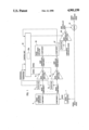
- FIG. 1 is a block diagram of a preferred embodiment of the system of the invention.
- unit 1 will preferably be a conventional circuit known as a one television frame differentiator. Such a conventional circuit accepts a television signal, generates a delayed television signal therefrom (by delaying the original signal by a period corresponding to one television signal frame), and subtracts the delayed television signal from the original signal.
- unit 1 will preferably be a digital television frame differentiator suitable for processing such a digital television signal to generate a set of parallel bit streams representing the digitized noise portion of the digital television signal.
- the noise signal emerging from unit 1 is separated into "n" frequency components (where n is a positive integer greater than one) in noise component separator 3.
- separator 3 includes conventional circuitry for performing a Walsh-Hadamard time domain to frequency domain transform on th noise signal supplied thereto, and separating the transformed noise signal into n frequency components, each having a distinct frequency spectrum.
- Each of identical detectors 5 through 12 receives a different one of the eight frequency components emerging from separator 3.
- Each of identical gain-controlled amplifiers 15 through 22 also receives a different one of the eight frequency components emerging from separator 3.
- Each detector measures a parameter characterizing the amplitude of the frequency component it receives, and supplies a feedback signal indicative of the measured parameter to control unit 23.
- each of detectors 5 through 12 is a digital comparator, and includes a low-pass filter for filtering the feedback signal to be supplied to control unit 23 (to provide a long-term valuation of its corresponding noise component).
- Control unit 23 is a programmed microprocessor including a memory unit 23a. Control unit 23 is programmed to supply a gain control signal to each of amplifiers 15 through 22 in response to each of the feedback signals received from detectors 5 through 12, respectively. Each of detectors 5 through 12 is associated with a minimum (threshold) noise value, and each of amplifiers 15 through 22 is associated with range of possible gain values bounded by a minimum gain value and a maximum gain value. All such minimum and maximum values (noise values and gain values) are determined by the system operator in accordance with the expected average noise levels for each of the frequency components emerging from unit 3 under expected operating conditions, and all gain values in the range and threshold noise values are written into memory unit 23a (for example, by setting appropriate switches). For example, if the "nth" frequency component supplied to detector 12 will likely have large amplitude, all parameters for that component will be selected to be correspondingly high.
- Control unit 23 is programmed to perform the following algorithm: (a) accept the operator-specified initialization parameters (the above-mentioned noise values and gain values) and determine a nominal gain control value for each frequency component (with each nominal gain control value selected from the operator-specified gain value range); (b) select the next frequency component to be tested; (c) compare the detector-supplied feedback signal (for the selected frequency component) with the system operator-supplied threshold noise signal (for the selected frequency component); (d) if the threshold signal level does not exceed the feedback noise signal level, generate (and supply to the gain controlled amplifier for the selected frequency component) a gain control signal having a gain value incrementally higher than the nominal gain control value, with the constraint that such incrementally higher gain level must not exceed the operator-specified maximum gain value; (e) if the feedback signal level is less than the threshold noise signal level, generate (and supply to the gain controlled amplifier for the selected frequency component) a gain control signal having a gain value incrementally lower than the nominal gain control value, with the constraint that such incrementally lower gain
- each of gain-controlled amplifiers 15 through 22 is a writable memory unit (preferably a random-access memory unit) employed in a standard manner as a data look-up table.
- control unit 23 writes a desired set of gain values into each of amplifiers 15-22 so that each set of gain values comprises a data look-up table in the relevant amplifier.
- Control unit 23 then causes each amplifier to apply the appropriate gain value (from the look-up table stored therein) to the frequency component received by each such amplifier in accordance with the algorithm set forth in the preceding paragraph.
- each of detectors 5 through 12 is also a writable memory unit (preferably a random-access memory unit) employed in a standard manner as a data look-up table.
- control unit 23 writes a desired set of noise level values into each of detectors 5-12 so that each set of noise level values comprises a data look-up table in the relevant detector.
- Each detector then functions as a digital comparator to output the noise level value (from the set of values stored therein) corresponding to the frequency component received by each such detector.
- each detector will output a special bit indicative of whether the incident frequency component's noise level exceeds the noise level threshold (currently stored in the detector) for such frequency band.
- each detector bit is low-pass filtered before it is supplied as a feedback signal to control unit 23.
- the gain controlled component signals emerging from amplifiers 15-22 are supplied to noise component collator unit 25.
- a conventional inverse Walsh-Hadamard transformation unit is suitable for use as unit 25, in an embodiment in which separator unit 3 is a Walsh-Hadamard transformation unit.
- Unit 25 will combine the individual gain controlled component signals to generate a component controlled noise signal whose frequency amplitude spectrum is determined by the amount of gain applied by each of gain controlled amplifiers 15-22 to the frequency components of the input noise signal emerging from unit 1.
- the component controlled noise signal may be directly added to the unprocessed, noisy signal in addition unit 31.
- the component controlled noise signal may be supplied to noise level detector 27 and to gain controlled amplifier 29, as shown in FIG. 1.
- Detector 27 measures a parameter characterizing the amplitude of the component controlled noise signal, and supplies a feedback signal indicative of the measured parameter to control unit 23.
- Control unit 23 may be programmed in a conventional manner (i.e., as in conventional automatic noise reduction systems) to supply a gain control signal to amplifier 29 in response to the feedback signal received from detector 25.
- Detector 27 and amplifier 29 may be implemented as writable memory units, just as detectors 5-12 and amplifiers 15-22, and employed in a standard manner as data look-up tables.
- the gain controlled noise signal emerging from amplifier 29 will have an average amplitude determined by the gain applied by amplifier 29, while the relative amplitudes of its frequency component is determined by the gains applied by the individual amplifiers 15-22.
- the gain controlled noise signal from amplifier 29 may be supplied to adder unit 31, in which it is combined with the unprocessed, noisy signal (which may be a television signal) whose noise component is extracted in unit 1. It will be appreciated that the average amplitude of the noise signal emerging from unit 1 (and hence the average amplitude of the noise signal emerging from amplifier 29) will have opposite sign as the average amplitude of the unprocessed, noisy signal supplied as the input to unit 1. Thus, addition of the gain controlled noise signal from amplifier 29 to the unprocessed, noisy signal will partially cancel the noise portion of the unprocessed, noisy signal.
- a computer programmer of ordinary skill in the art will be able readily to generate appropriate software (or firmware) for programming control unit 23 to implement the above-described operations.
Abstract
Description
Claims (27)
Priority Applications (2)
| Application Number | Priority Date | Filing Date | Title |
|---|---|---|---|
| US07/274,820 US4901150A (en) | 1988-11-22 | 1988-11-22 | Automatic noise reduction for individual frequency components of a signal |
| JP1304209A JPH02180469A (en) | 1988-11-22 | 1989-11-22 | Automatic noise removing circuit |
Applications Claiming Priority (1)
| Application Number | Priority Date | Filing Date | Title |
|---|---|---|---|
| US07/274,820 US4901150A (en) | 1988-11-22 | 1988-11-22 | Automatic noise reduction for individual frequency components of a signal |
Publications (1)
| Publication Number | Publication Date |
|---|---|
| US4901150A true US4901150A (en) | 1990-02-13 |
Family
ID=23049733
Family Applications (1)
| Application Number | Title | Priority Date | Filing Date |
|---|---|---|---|
| US07/274,820 Expired - Lifetime US4901150A (en) | 1988-11-22 | 1988-11-22 | Automatic noise reduction for individual frequency components of a signal |
Country Status (2)
| Country | Link |
|---|---|
| US (1) | US4901150A (en) |
| JP (1) | JPH02180469A (en) |
Cited By (14)
| Publication number | Priority date | Publication date | Assignee | Title |
|---|---|---|---|---|
| US5140424A (en) * | 1987-07-07 | 1992-08-18 | Canon Kabushiki Kaisha | Image signal processing apparatus with noise reduction |
| US5142643A (en) * | 1989-10-03 | 1992-08-25 | Sharp Kabushiki Kaisha | Sampled video signal generating device for improving deviation based on difference of circuit characteristics among channels |
| EP0575995A2 (en) * | 1992-06-25 | 1993-12-29 | Matsushita Electric Industrial Co., Ltd. | Noise reduction apparatus |
| US5367340A (en) * | 1990-10-19 | 1994-11-22 | Gec-Marconi Limited | Apparatus and method for noise reduction of video signal dependent upon video gain |
| US5428832A (en) * | 1992-03-11 | 1995-06-27 | Matsushita Electric Industrial Co., Ltd. | Noise suppression apparatus |
| EP0660595A2 (en) * | 1993-12-20 | 1995-06-28 | Matsushita Electric Industrial Co., Ltd. | A noise reducer |
| US5430894A (en) * | 1992-03-11 | 1995-07-04 | Matsushita Electric Industrial Co., Ltd. | Radio receiver noise suppression system |
| US5465413A (en) * | 1993-03-05 | 1995-11-07 | Trimble Navigation Limited | Adaptive noise cancellation |
| US5678218A (en) * | 1993-02-05 | 1997-10-14 | Nippon Telegraph And Telephone | Circuit for removing random FM noise |
| US5818972A (en) * | 1995-06-07 | 1998-10-06 | Realnetworks, Inc. | Method and apparatus for enhancing images using helper signals |
| US5926224A (en) * | 1995-07-31 | 1999-07-20 | Sony Corporation | Imaging, system, video processing apparatus, encoding apparatus, encoding method, and method of removing random noise |
| KR20020023523A (en) * | 2000-09-22 | 2002-03-29 | 박규영 | A Camera for revising illumination |
| US6611794B1 (en) * | 2000-04-20 | 2003-08-26 | Southwest Research Institute | Signal amplitude restoration apparatus and method |
| US7130433B1 (en) * | 1997-11-12 | 2006-10-31 | Pioneer Electronic Corporation | Noise reduction apparatus and noise reduction method |
Families Citing this family (1)
| Publication number | Priority date | Publication date | Assignee | Title |
|---|---|---|---|---|
| JPH05304622A (en) * | 1992-04-24 | 1993-11-16 | Toshiba Corp | Noise detector and noise reduction device |
Citations (5)
| Publication number | Priority date | Publication date | Assignee | Title |
|---|---|---|---|---|
| US4044381A (en) * | 1974-06-03 | 1977-08-23 | Hitachi, Ltd. | Automatic waveform equalizing system for television receiver |
| US4167755A (en) * | 1976-12-14 | 1979-09-11 | Sony Corporation | Solid state television camera |
| US4504864A (en) * | 1982-12-30 | 1985-03-12 | International Business Machines Corporation | Nonlinear filtering of gray scale images |
| US4554514A (en) * | 1984-12-21 | 1985-11-19 | Rca Corporation | Predistortion circuit with feedback |
| US4698680A (en) * | 1985-12-24 | 1987-10-06 | Rca Corporation | Digital correlation apparatus as for a television deghosting system |
-
1988
- 1988-11-22 US US07/274,820 patent/US4901150A/en not_active Expired - Lifetime
-
1989
- 1989-11-22 JP JP1304209A patent/JPH02180469A/en active Pending
Patent Citations (5)
| Publication number | Priority date | Publication date | Assignee | Title |
|---|---|---|---|---|
| US4044381A (en) * | 1974-06-03 | 1977-08-23 | Hitachi, Ltd. | Automatic waveform equalizing system for television receiver |
| US4167755A (en) * | 1976-12-14 | 1979-09-11 | Sony Corporation | Solid state television camera |
| US4504864A (en) * | 1982-12-30 | 1985-03-12 | International Business Machines Corporation | Nonlinear filtering of gray scale images |
| US4554514A (en) * | 1984-12-21 | 1985-11-19 | Rca Corporation | Predistortion circuit with feedback |
| US4698680A (en) * | 1985-12-24 | 1987-10-06 | Rca Corporation | Digital correlation apparatus as for a television deghosting system |
Cited By (17)
| Publication number | Priority date | Publication date | Assignee | Title |
|---|---|---|---|---|
| US5140424A (en) * | 1987-07-07 | 1992-08-18 | Canon Kabushiki Kaisha | Image signal processing apparatus with noise reduction |
| US5142643A (en) * | 1989-10-03 | 1992-08-25 | Sharp Kabushiki Kaisha | Sampled video signal generating device for improving deviation based on difference of circuit characteristics among channels |
| US5367340A (en) * | 1990-10-19 | 1994-11-22 | Gec-Marconi Limited | Apparatus and method for noise reduction of video signal dependent upon video gain |
| US5430894A (en) * | 1992-03-11 | 1995-07-04 | Matsushita Electric Industrial Co., Ltd. | Radio receiver noise suppression system |
| US5428832A (en) * | 1992-03-11 | 1995-06-27 | Matsushita Electric Industrial Co., Ltd. | Noise suppression apparatus |
| EP0575995A3 (en) * | 1992-06-25 | 1994-07-20 | Matsushita Electric Ind Co Ltd | Noise reduction apparatus |
| US5425114A (en) * | 1992-06-25 | 1995-06-13 | Matsushita Electric Industrial Co., Ltd. | Noise reduction apparatus |
| EP0575995A2 (en) * | 1992-06-25 | 1993-12-29 | Matsushita Electric Industrial Co., Ltd. | Noise reduction apparatus |
| US5678218A (en) * | 1993-02-05 | 1997-10-14 | Nippon Telegraph And Telephone | Circuit for removing random FM noise |
| US5465413A (en) * | 1993-03-05 | 1995-11-07 | Trimble Navigation Limited | Adaptive noise cancellation |
| EP0660595A3 (en) * | 1993-12-20 | 1995-11-29 | Matsushita Electric Ind Co Ltd | A noise reducer. |
| EP0660595A2 (en) * | 1993-12-20 | 1995-06-28 | Matsushita Electric Industrial Co., Ltd. | A noise reducer |
| US5818972A (en) * | 1995-06-07 | 1998-10-06 | Realnetworks, Inc. | Method and apparatus for enhancing images using helper signals |
| US5926224A (en) * | 1995-07-31 | 1999-07-20 | Sony Corporation | Imaging, system, video processing apparatus, encoding apparatus, encoding method, and method of removing random noise |
| US7130433B1 (en) * | 1997-11-12 | 2006-10-31 | Pioneer Electronic Corporation | Noise reduction apparatus and noise reduction method |
| US6611794B1 (en) * | 2000-04-20 | 2003-08-26 | Southwest Research Institute | Signal amplitude restoration apparatus and method |
| KR20020023523A (en) * | 2000-09-22 | 2002-03-29 | 박규영 | A Camera for revising illumination |
Also Published As
| Publication number | Publication date |
|---|---|
| JPH02180469A (en) | 1990-07-13 |
Similar Documents
| Publication | Publication Date | Title |
|---|---|---|
| US4901150A (en) | Automatic noise reduction for individual frequency components of a signal | |
| US5321511A (en) | Horizontal edge compensation circuit for a digital image processor | |
| DE69907380T2 (en) | decoding apparatus | |
| US5050217A (en) | Dynamic noise reduction and spectral restoration system | |
| EP0328346A2 (en) | Noise reduction circuits | |
| US5136386A (en) | Video signal noise reduction circuit preceded by a picture quality control circuit | |
| US5446502A (en) | Method and apparatus for filtering signals having a filter in which signal amplitudes are allocated to a quantized, two-dimensional reference plane | |
| US5262863A (en) | Video signal processor having an adjustable noise cancelling circuit | |
| US4403255A (en) | FM/TV Automatic gain control system | |
| DE69819973T2 (en) | Noise reduction system for audio | |
| US5218438A (en) | Picture aperture correction circuit | |
| US5150214A (en) | Method and circuit for correction of horizontal edges | |
| JPH07154900A (en) | Circuit for stereo signal transformation and method of operation of is circuit | |
| EP0720359B1 (en) | Method and Apparatus for image enhancement | |
| GB2237161A (en) | Correction of horizontal edges in a video system | |
| US5446503A (en) | Vertical detail enhancement with stepped return coring | |
| KR100437755B1 (en) | Image outline enhancer | |
| US8259877B2 (en) | Method and device for automatic gain control with limited jitter | |
| EP0451283B1 (en) | Processing circuit for video signal | |
| JPH09130816A (en) | Signal processing circuit | |
| KR960013222B1 (en) | Edge - enhancing circuit for digital video signal processing system | |
| JP3022628B2 (en) | Edge enhancement circuit | |
| KR970008460B1 (en) | Horizontal edge correcting circuit for digital video processing | |
| JPH05211662A (en) | Digital image special effect device and method | |
| JPS59111482A (en) | Noise suppression circuit |
Legal Events
| Date | Code | Title | Description |
|---|---|---|---|
| AS | Assignment |
Owner name: SONY CORPORATION Free format text: ASSIGNMENT OF ASSIGNORS INTEREST.;ASSIGNORS:KLINGELHOFER, MARC;PERRY, VINSON R.;REEL/FRAME:004980/0983 Effective date: 19881116 Owner name: SONY CORPORATION, JAPAN Free format text: ASSIGNMENT OF ASSIGNORS INTEREST;ASSIGNORS:KLINGELHOFER, MARC;PERRY, VINSON R.;REEL/FRAME:004980/0983 Effective date: 19881116 |
|
| STCF | Information on status: patent grant |
Free format text: PATENTED CASE |
|
| FEPP | Fee payment procedure |
Free format text: PAYOR NUMBER ASSIGNED (ORIGINAL EVENT CODE: ASPN); ENTITY STATUS OF PATENT OWNER: LARGE ENTITY |
|
| FPAY | Fee payment |
Year of fee payment: 4 |
|
| FEPP | Fee payment procedure |
Free format text: PAYER NUMBER DE-ASSIGNED (ORIGINAL EVENT CODE: RMPN); ENTITY STATUS OF PATENT OWNER: LARGE ENTITY Free format text: PAYOR NUMBER ASSIGNED (ORIGINAL EVENT CODE: ASPN); ENTITY STATUS OF PATENT OWNER: LARGE ENTITY |
|
| FPAY | Fee payment |
Year of fee payment: 8 |
|
| FPAY | Fee payment |
Year of fee payment: 12 |