US4424598A - Multi-mode bath module - Google Patents
Multi-mode bath module Download PDFInfo
- Publication number
- US4424598A US4424598A US06/399,795 US39979582A US4424598A US 4424598 A US4424598 A US 4424598A US 39979582 A US39979582 A US 39979582A US 4424598 A US4424598 A US 4424598A
- Authority
- US
- United States
- Prior art keywords
- recessed portion
- module
- walls
- accordance
- interior
- Prior art date
- Legal status (The legal status is an assumption and is not a legal conclusion. Google has not performed a legal analysis and makes no representation as to the accuracy of the status listed.)
- Expired - Fee Related
Links
- XLYOFNOQVPJJNP-UHFFFAOYSA-N water Substances O XLYOFNOQVPJJNP-UHFFFAOYSA-N 0.000 claims description 17
- 239000003595 mist Substances 0.000 abstract description 10
- 238000003287 bathing Methods 0.000 description 3
- 238000009428 plumbing Methods 0.000 description 3
- 238000010276 construction Methods 0.000 description 2
- NIXOWILDQLNWCW-UHFFFAOYSA-N acrylic acid group Chemical group C(C=C)(=O)O NIXOWILDQLNWCW-UHFFFAOYSA-N 0.000 description 1
- 230000004075 alteration Effects 0.000 description 1
- 230000000881 depressing effect Effects 0.000 description 1
- 230000000994 depressogenic effect Effects 0.000 description 1
- 238000007599 discharging Methods 0.000 description 1
- 230000000694 effects Effects 0.000 description 1
- 230000002708 enhancing effect Effects 0.000 description 1
- 238000009434 installation Methods 0.000 description 1
- 239000000463 material Substances 0.000 description 1
- 238000000034 method Methods 0.000 description 1
- 238000012986 modification Methods 0.000 description 1
- 230000004048 modification Effects 0.000 description 1
- 230000008569 process Effects 0.000 description 1
- 238000007666 vacuum forming Methods 0.000 description 1
Images


Classifications
-
- A—HUMAN NECESSITIES
- A61—MEDICAL OR VETERINARY SCIENCE; HYGIENE
- A61H—PHYSICAL THERAPY APPARATUS, e.g. DEVICES FOR LOCATING OR STIMULATING REFLEX POINTS IN THE BODY; ARTIFICIAL RESPIRATION; MASSAGE; BATHING DEVICES FOR SPECIAL THERAPEUTIC OR HYGIENIC PURPOSES OR SPECIFIC PARTS OF THE BODY
- A61H33/00—Bathing devices for special therapeutic or hygienic purposes
- A61H33/60—Components specifically designed for the therapeutic baths of groups A61H33/00
- A61H33/601—Inlet to the bath
- A61H33/6021—Nozzles
- A61H33/6036—Hand-held connected to a supply hose
-
- A—HUMAN NECESSITIES
- A61—MEDICAL OR VETERINARY SCIENCE; HYGIENE
- A61H—PHYSICAL THERAPY APPARATUS, e.g. DEVICES FOR LOCATING OR STIMULATING REFLEX POINTS IN THE BODY; ARTIFICIAL RESPIRATION; MASSAGE; BATHING DEVICES FOR SPECIAL THERAPEUTIC OR HYGIENIC PURPOSES OR SPECIFIC PARTS OF THE BODY
- A61H33/00—Bathing devices for special therapeutic or hygienic purposes
- A61H33/0087—Therapeutic baths with agitated or circulated water
-
- A—HUMAN NECESSITIES
- A61—MEDICAL OR VETERINARY SCIENCE; HYGIENE
- A61N—ELECTROTHERAPY; MAGNETOTHERAPY; RADIATION THERAPY; ULTRASOUND THERAPY
- A61N5/00—Radiation therapy
- A61N5/06—Radiation therapy using light
- A61N5/0613—Apparatus adapted for a specific treatment
- A61N5/0614—Tanning
-
- A—HUMAN NECESSITIES
- A61—MEDICAL OR VETERINARY SCIENCE; HYGIENE
- A61H—PHYSICAL THERAPY APPARATUS, e.g. DEVICES FOR LOCATING OR STIMULATING REFLEX POINTS IN THE BODY; ARTIFICIAL RESPIRATION; MASSAGE; BATHING DEVICES FOR SPECIAL THERAPEUTIC OR HYGIENIC PURPOSES OR SPECIFIC PARTS OF THE BODY
- A61H9/00—Pneumatic or hydraulic massage
- A61H9/0021—Hydraulic massage
- A61H2009/0035—Hydraulic massage with cabin for the whole body
-
- A—HUMAN NECESSITIES
- A61—MEDICAL OR VETERINARY SCIENCE; HYGIENE
- A61H—PHYSICAL THERAPY APPARATUS, e.g. DEVICES FOR LOCATING OR STIMULATING REFLEX POINTS IN THE BODY; ARTIFICIAL RESPIRATION; MASSAGE; BATHING DEVICES FOR SPECIAL THERAPEUTIC OR HYGIENIC PURPOSES OR SPECIFIC PARTS OF THE BODY
- A61H9/00—Pneumatic or hydraulic massage
- A61H9/0021—Hydraulic massage
- A61H2009/0042—Hydraulic massage with water recirculation
-
- A—HUMAN NECESSITIES
- A61—MEDICAL OR VETERINARY SCIENCE; HYGIENE
- A61H—PHYSICAL THERAPY APPARATUS, e.g. DEVICES FOR LOCATING OR STIMULATING REFLEX POINTS IN THE BODY; ARTIFICIAL RESPIRATION; MASSAGE; BATHING DEVICES FOR SPECIAL THERAPEUTIC OR HYGIENIC PURPOSES OR SPECIFIC PARTS OF THE BODY
- A61H33/00—Bathing devices for special therapeutic or hygienic purposes
- A61H33/005—Electrical circuits therefor
- A61H2033/0054—Electrical circuits therefor with liquid level detectors
-
- A—HUMAN NECESSITIES
- A61—MEDICAL OR VETERINARY SCIENCE; HYGIENE
- A61H—PHYSICAL THERAPY APPARATUS, e.g. DEVICES FOR LOCATING OR STIMULATING REFLEX POINTS IN THE BODY; ARTIFICIAL RESPIRATION; MASSAGE; BATHING DEVICES FOR SPECIAL THERAPEUTIC OR HYGIENIC PURPOSES OR SPECIFIC PARTS OF THE BODY
- A61H33/00—Bathing devices for special therapeutic or hygienic purposes
- A61H33/005—Electrical circuits therefor
- A61H2033/0058—Electrical circuits therefor controlled by the user
- A61H2033/0062—Electrical circuits therefor controlled by the user with electro-pneumatic or -hydraulic switches
-
- A—HUMAN NECESSITIES
- A61—MEDICAL OR VETERINARY SCIENCE; HYGIENE
- A61H—PHYSICAL THERAPY APPARATUS, e.g. DEVICES FOR LOCATING OR STIMULATING REFLEX POINTS IN THE BODY; ARTIFICIAL RESPIRATION; MASSAGE; BATHING DEVICES FOR SPECIAL THERAPEUTIC OR HYGIENIC PURPOSES OR SPECIFIC PARTS OF THE BODY
- A61H33/00—Bathing devices for special therapeutic or hygienic purposes
- A61H33/06—Artificial hot-air or cold-air baths; Steam or gas baths or douches, e.g. sauna or Finnish baths
- A61H2033/068—Steam baths
-
- A—HUMAN NECESSITIES
- A61—MEDICAL OR VETERINARY SCIENCE; HYGIENE
- A61H—PHYSICAL THERAPY APPARATUS, e.g. DEVICES FOR LOCATING OR STIMULATING REFLEX POINTS IN THE BODY; ARTIFICIAL RESPIRATION; MASSAGE; BATHING DEVICES FOR SPECIAL THERAPEUTIC OR HYGIENIC PURPOSES OR SPECIFIC PARTS OF THE BODY
- A61H2201/00—Characteristics of apparatus not provided for in the preceding codes
- A61H2201/10—Characteristics of apparatus not provided for in the preceding codes with further special therapeutic means, e.g. electrotherapy, magneto therapy or radiation therapy, chromo therapy, infrared or ultraviolet therapy
-
- A—HUMAN NECESSITIES
- A61—MEDICAL OR VETERINARY SCIENCE; HYGIENE
- A61N—ELECTROTHERAPY; MAGNETOTHERAPY; RADIATION THERAPY; ULTRASOUND THERAPY
- A61N5/00—Radiation therapy
- A61N5/06—Radiation therapy using light
- A61N2005/0664—Details
- A61N2005/0668—Apparatus adapted for operation in a moist environment, e.g. bath or shower
Definitions
- the present invention relates generally to shower/tub constructions and, more particularly to self-contained bathing or shower installations. Specifically, the present invention concerns a novel multi-mode bath module providing a variety of modes of operation including whirlpool, steam, mist and tanning modes in addition to normal bath and shower.
- An object of the present invention is to provide multi-mode bath module which is easy to install, relatively inexpensive and extremely convenient in use for the user.
- a more specific object of the invention is to provide a means of permitting the user to safely control the modes of operation or functioning of the bath module without leaving the interior thereof, even when the user is sitting or standing in water.
- a further object is to provide enhanced safety and convenience to the user through provision of readily accessible, but non-protruding, storage and grab bar facility within the station.
- a multi-mode bath module comprises spaced apart top and bottom walls with opposed pairs of side and end walls extending generally vertically therebetween to jointly therewith define the interior of the module.
- the walls are joined integrally to define a unitary shell-like structure.
- One of the side walls has a relatively large opening to provide user access to the interior.
- Suitable doors preferrably sliding doors, are mounted to open and close the access.
- the walls also have a plurality of relatively small openings in which are mounted the mode determining inputs, such as an ultra-violet lamp for tanning, mist heads, nozzles for whirlpool and steam heads. Connected to the inputs are facilities for enabling operation thereof.
- Such facilities include delivery systems including the electrical lines (for the lamp), a steam generator, whirlpool pump and related plumbing. Such facilities further include operating systems for the delivery systems.
- the operating systems are of the electro-pneumatic type wherein electric switching is responsive to pneumatic control signals. Controls for producing the pneumatic control signals are located within the station interior for the user so that electrical switching can be safely accomplished through the expedient of pneumatic control.
- the pneumatic controls are located within a recessed portion of one of the vertical walls, preferrably the side wall opposite that of the access opening.
- Recessed storage and grab bar compartments are also provided in the illustrated embodiment to enhance convenience and safety.
- the illustrated embodiment advantageously locates the pneumatic controls in the recessed storage compartment, the storage compartment having shelves for supporting vanity items and a sliding door to prevent the vanity items from accidentally falling out.
- Another feature of the preferred embodiment relates to the convenient and safe housing of a hand held shower unit within the same recessed storage compartment which houses the pneumatic controls and vanity shelves.
- the shelves extend less than full length of the compartment to afford room for the pneumatic controls and hand held shower unit.
- the lower portions of the vertical walls together with the bottom wall define a tub for regular bathing and for the whirlpool, the recessed grab bar compartment being formed in the vertical side wall opposite the access immediately above the lower tub defining portion thereof and the recessed storage compartment being formed in the same wall immediately above the grab bar compartment.
- air volume controls for controlling the intensity of the whirlpool jet inputs are disposed in a recessed location at the base of the grab bar recess compartment.
- FIG. 1 is a perspective view showing the front and portions of the interior of a multi-mode bath module in accordance with the present invention as installed in a user's bathroom;
- FIG. 2 is a front elevational view of the module of FIG. 1;
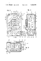
- FIG. 3 is a sectional view taken, as indicated, along the line 3--3 of FIG. 2;
- FIG. 4 is a sectional view taken, as indicated, along the line 4--4 of FIG. 3;
- FIG. 5 is a perspective view showing the lower rear portion of the module of FIG. 1;
- FIG. 6 is an enlarged fragmentary perspective view of the recessed storage compartment.
- FIG. 7 is a simplified schematic of the delivery and operating systems for the module.
- a multi-mode bath module 10 in accordance with the invention is shown in its presently preferred form comprising a hollow, shell-like structure that includes spaced apart top and bottom walls 12, 14 with opposed pairs of side walls 16, 18 and end walls 20, 22 extending generally vertically there between to jointly therwith define the interior of the module.
- the walls 12, 14, 16, 18, 20 and 22 are joined integrally to thereby define a monolithic shell-like structure.
- the walls are formed via a vacuum forming process of a thermal plastic material such as acrylic.
- the lower portions 16L, 18L of side walls 16, 18 and the lower portions 20L, 22L of end walls 20, 22 together with the bottom wall 14 define a tub like structure suitable for bathing and/or whirlpool as will be described hereinafter.
- the upper portion of the side wall 16 has a relatively large opening 24 to provide user access to the interior, the opening being surrounded by an outwardly flared portion 16F of wall 16 which, in turn, integrally merges with a frontal facing wall 17.
- Sliding doors 26, 28 are guided by tracks 30, 32 mounted along the upper and lower surfaces of flared portion 16F to open and close the access.
- the upper portion of the other side wall 18 includes a planar region 18P which is offset outwardly (viewed from the interior) from the lower tub defining portion 18L thereof via a sloping portion 18A.
- Recessed storage and grab bar compartments 34, 36 are formed in the upper portion of side wall 18.
- the recessed storage compartment 34 includes a vertical back wall portion 38 offset outwardly (when viewed from the interior) from the planar region 18P.
- Upper, lower and a part of opposed end wall portions 40, 42, 44 and 46, respectively, extend transversely inwardly from the back wall portion 38 a distance beyond the planar region 18P and terminate substantially in a plane that is substantially complanar of the lower portion 18L of side wall 18.
- the recessed grab bar compartment 36 includes a back wall portion 48 similarly offset from planar region 18P and similar upper, lower and end wall portions 50, 52, 54 and 56, respectively.
- a grab bar 58 is suitably mounted to extend between end wall portions 54 and 56, as shown.
- the sloping portions 18A and a merging border 18B encircle compartments 34, 36 in picture frame like fashion.
- End wall 20 includes a plurality of relatively small openings or ports (not shown) to accommodate a standard fixed shower head 60, and valve and faucet assembly 62.
- a conventional mechanical drain lever 64 is mounted in conventional fashion to open and close a water drain 66 provided in the bottom wall 14.
- the multi-mode bath module 10 affords whirlpool, steam, tanning and mist functions in addition to standard bath and shower.
- mode determining inputs are provided.
- the inputs comprise a plurality of standard water jet nozzels 68 mounted through appropriate ports or openings in the lower portions 16L, 18L, 20L and 22L of walls 16, 18, 20 and 22, there being two nozzels 68 located along portions 16L, 18L and 20L and a single nozzel located along wall portion 22L.
- the input comprises a standard steam head 70 mounted through a suitable port located along wall portion 20L.
- the mode determining input in the case of the tanning mode comprises an ultraviolet lamp 72 mounted through an appropriate opening in the top wall 12.
- the mode determining inputs comprise a pair of standard mist or rain heads 74 also mounted through suitable openings in the top wall 12.
- Facilities for enabling operation of the mode determining inputs 68, 70, 72 and 74 comprise delivery and operating systems. As will be described, such facilities permit the user to safely select and vary the modes of operation without leaving the interior of the module.
- the delivery system for the whirlpool mode includes a pump 76, and plumbing comprising water pipe line 78 for delivering water under pressure to the whirlpool jets 68 and a water pipe line 80 for returning water to pump 76.
- water pipe line 80 is connected to a strainer 82 mounted in an opening of the lower portion 10L of wall 18.
- the delivery system for the steam mode includes a steam generator 84 and steam line 86 connected between the generator 84 and the steam head 70.
- the delivery system for the mist mode includes a solenoid valve 88 (see FIG. 5) and water lines 90, 92. As shown line 90 runs from valve 80 to the mist heads 74 while line 92 runs from valve 88 to a mixing valve 94 (FIG. 5) which is controlled by the personal shower control 96 located in the recessed storage compartment 34, as will be described. Hot and cold water lines 98, 100 deliver water to the mixing valve 94.
- the delivery system simply comprises electrical power line 128 (shown in FIG. 7 only).
- the operating system for the whirlpool, steam, mist and tanning modes comprises an electro-pneumatic switch unit 104 which responds to pneumatic control signals received from pneumatic control lines 106, 108, 110 and 112.
- the control lines 106, 108, 110 and 112 are respectively connected to control push buttons 114, 116, 118 and 120, respectively which are mounted in the recessed storage compartment 34 as best shown in FIG. 6.
- the switch unit 104 incorporates four air switches, each being connected to a separate one of the lines 106-112 which comprise flexible air hoses.
- a control signal in the form of a burst of air is forced through the corresponding hose to the corresponding air switch to turn the same either “on” or “off” depending upon the state of the switch.
- the air switches are of conventional design and readily available, as are the push button controls.
- the four air switches of unit 104 are connected to switch power from a common input power line 122 to four output power lines 124, 126, 128 and 130 respectively connected to drive the steam generator 84, the pump 76, the ultraviolet lamp 72 and the solenoid valve 88.
- the air switches include timing circuits, programmed to provide a 10 minute cycle for each of the modes. If the user does not wish to continue a mode for a full 10 minute span, the mode can be terminated by turning the air switch "off" by depressing the corresponding control push button.
- the presently preferred embodiment imcorporates a pair of control valves 132, 134 located along the bottom wall 52 of the recessed grab bar compartment 36.
- the operation of such valves is well known and therefore will be only briefly discussed.
- the whirlpool jet nozzels 68 have air inlets 102 associated therewith from which air is drawn into the discharging jet stream of water (to form bubbles).
- the air inlets are connected via piping to the valves 132, 134.
- the valves operate to control the amount of air which can be drawn into the jet streams (via venturi effect) by opening and closing the piping to the atmosphere.
- shelves 136 are mounted in recessed storage compartment 34 which extend less than the full length thereof.
- a divider 138 separates the shelves from the remainder of the compartment and defines an area for locating a conventional hand held shower consisting of a shower head 140 and flexible hose 142.
- a hanger 144 is provided in the compartment for hanging the shower head 140.
- the hose 142 is connected via a water line 145 to valve 94.
- head 140 includes a turn off cock.
- the recessed storage compartment 34 can be closed via sliding doors 146, 148 mounted on tracks 150, 152 disposed along the upper and lower wall portions 40, 42.
- the bottom wall 52 of recessed grab bar compartment 36 and the bottom of the flared portion 16F serves as a seat on which a removable bench unit 154 may be rested.
Landscapes
- Health & Medical Sciences (AREA)
- Public Health (AREA)
- Life Sciences & Earth Sciences (AREA)
- Veterinary Medicine (AREA)
- General Health & Medical Sciences (AREA)
- Animal Behavior & Ethology (AREA)
- Physical Education & Sports Medicine (AREA)
- Rehabilitation Therapy (AREA)
- Pain & Pain Management (AREA)
- Epidemiology (AREA)
- Engineering & Computer Science (AREA)
- Biomedical Technology (AREA)
- Pathology (AREA)
- Nuclear Medicine, Radiotherapy & Molecular Imaging (AREA)
- Radiology & Medical Imaging (AREA)
- Devices For Medical Bathing And Washing (AREA)
Abstract
Description
Claims (6)
Priority Applications (1)
| Application Number | Priority Date | Filing Date | Title |
|---|---|---|---|
| US06/399,795 US4424598A (en) | 1982-07-19 | 1982-07-19 | Multi-mode bath module |
Applications Claiming Priority (1)
| Application Number | Priority Date | Filing Date | Title |
|---|---|---|---|
| US06/399,795 US4424598A (en) | 1982-07-19 | 1982-07-19 | Multi-mode bath module |
Publications (1)
| Publication Number | Publication Date |
|---|---|
| US4424598A true US4424598A (en) | 1984-01-10 |
Family
ID=23580998
Family Applications (1)
| Application Number | Title | Priority Date | Filing Date |
|---|---|---|---|
| US06/399,795 Expired - Fee Related US4424598A (en) | 1982-07-19 | 1982-07-19 | Multi-mode bath module |
Country Status (1)
| Country | Link |
|---|---|
| US (1) | US4424598A (en) |
Cited By (39)
| Publication number | Priority date | Publication date | Assignee | Title |
|---|---|---|---|---|
| JPS63195061U (en) * | 1987-06-04 | 1988-12-15 | ||
| FR2617889A1 (en) * | 1987-07-08 | 1989-01-13 | Mille Daniel | Single unit environment intended for care of the body and for relaxation |
| US4945908A (en) * | 1985-11-07 | 1990-08-07 | Karl Schneider | Balneo-phototherapeutical treatment process and bath |
| US4987619A (en) * | 1988-09-07 | 1991-01-29 | Smith Lee A | Modular bathing cabinet and method of fabricating same |
| US4989600A (en) * | 1989-08-16 | 1991-02-05 | Collier Joseph M | Tanning pod |
| US5027450A (en) * | 1989-07-21 | 1991-07-02 | Harold Lang | Extendible and retractable spa jet |
| US5093942A (en) * | 1989-07-21 | 1992-03-10 | Harold Lang | Extendible and retractable spa jet |
| US5163426A (en) * | 1987-06-26 | 1992-11-17 | Brigham And Women's Hospital | Assessment and modification of a subject's endogenous circadian cycle |
| US5167228A (en) * | 1987-06-26 | 1992-12-01 | Brigham And Women's Hospital | Assessment and modification of endogenous circadian phase and amplitude |
| US5230107A (en) * | 1992-02-12 | 1993-07-27 | Boris Alperovich | Multipurpose bath apparatus |
| US5312179A (en) * | 1991-08-09 | 1994-05-17 | Trayco, Inc. | Cabinet surround |
| US5545192A (en) * | 1987-06-26 | 1996-08-13 | Brigham And Women's Hospital | Intermittent use of bright light to modify the circadian phase |
| WO1997013231A1 (en) * | 1995-10-06 | 1997-04-10 | Peter Theander | Remote control and indication system for electrical devices |
| US5738044A (en) * | 1996-01-25 | 1998-04-14 | Gaylinn; Glen Philip | Multiplexed gangable animal bathing stations |
| US5768721A (en) * | 1996-04-01 | 1998-06-23 | Guardian Equipment, Inc. | Emergency shower |
| US6076204A (en) * | 1994-08-11 | 2000-06-20 | Research Foundation Of State University Of New York | Modular bathing unit |
| US6443164B1 (en) | 2000-09-22 | 2002-09-03 | Spectrum Products, Inc. | Apparatus for automatic application of compositions to the skin |
| US6500197B1 (en) * | 1999-01-28 | 2002-12-31 | Vitasalin Ag | Full-body atomised bath and method for providing a full body atomised bath |
| US6567999B1 (en) * | 2002-01-14 | 2003-05-27 | Keith L. Thurner | Shower stall unit with integral tanning lights |
| US20030177572A1 (en) * | 2002-03-22 | 2003-09-25 | Jeanne Guerin | Aircraft passenger cleansing system |
| US20040073186A1 (en) * | 2002-10-15 | 2004-04-15 | Cameron Mickey G. | Apparatus for automatic application of compositions to the skin |
| US6820290B1 (en) | 2000-06-14 | 2004-11-23 | The Research Foundation Of Suny At Buffalo | Movable bathroom fixtures |
| US20050120474A1 (en) * | 2002-07-05 | 2005-06-09 | Wegdam Pieter M. | Shower device with tanning device and method for use thereof |
| US20050132488A1 (en) * | 2003-12-23 | 2005-06-23 | Arcangelo Biondo | Whirlpool tup and faucet/handheld shower combination |
| US20050210576A1 (en) * | 2004-03-23 | 2005-09-29 | The Boeing Company | Shower System |
| US20060064815A1 (en) * | 2004-09-24 | 2006-03-30 | The Boeing Company | Mist Delivery System |
| EP1686249A2 (en) | 2005-01-26 | 2006-08-02 | Jay S. Kim | Fluid swirling device |
| EP1688122A1 (en) * | 2005-02-04 | 2006-08-09 | Jurgen Klein | Sensory experience method and apparatus |
| US20060178280A1 (en) * | 2005-02-04 | 2006-08-10 | Jurgen Klein | Sensory experience method and apparatus |
| US20070186340A1 (en) * | 2003-11-21 | 2007-08-16 | Brian Gay | Coating apparatus and method |
| US20070267521A1 (en) * | 2006-05-20 | 2007-11-22 | Zhou Huasong | Automatic Elevating Shower or Faucet |
| US20080052816A1 (en) * | 2006-09-01 | 2008-03-06 | Gillis Keith D | Shower shelf and storage |
| US20090001862A1 (en) * | 2007-06-27 | 2009-01-01 | Deco Lav, Inc. | Adjustable Width Vanity and Method for Securing an Adjustable Width Vanity |
| US20100115693A1 (en) * | 2008-08-15 | 2010-05-13 | Victor Hoernig | Tub and shower surround with hidden storage |
| US20130097773A1 (en) * | 2011-04-13 | 2013-04-25 | Sussman-Automatic Corporation | Light assembly for a steamhead |
| US8646121B2 (en) * | 2007-06-19 | 2014-02-11 | Huan Thanh Nguyen | Steam and sauna shower panel |
| US9462885B2 (en) | 2014-06-20 | 2016-10-11 | Kohler Co. | Bathing area accessories |
| US9999565B2 (en) | 2015-04-06 | 2018-06-19 | Bernard E. Urfig | Steam shower system and device |
| US11779515B2 (en) | 2020-09-02 | 2023-10-10 | Bernard E. Urfig | Steam shower system and device |
-
1982
- 1982-07-19 US US06/399,795 patent/US4424598A/en not_active Expired - Fee Related
Cited By (49)
| Publication number | Priority date | Publication date | Assignee | Title |
|---|---|---|---|---|
| US4945908A (en) * | 1985-11-07 | 1990-08-07 | Karl Schneider | Balneo-phototherapeutical treatment process and bath |
| JPS63195061U (en) * | 1987-06-04 | 1988-12-15 | ||
| JPH0414602Y2 (en) * | 1987-06-04 | 1992-04-02 | ||
| US5176133A (en) * | 1987-06-26 | 1993-01-05 | Brigham And Women's Hospital | Assessment and modification of circadian phase and amplitude |
| US5545192A (en) * | 1987-06-26 | 1996-08-13 | Brigham And Women's Hospital | Intermittent use of bright light to modify the circadian phase |
| US5304212A (en) * | 1987-06-26 | 1994-04-19 | Brigham And Women's Hospital | Assessment and modification of a human subject's circadian cycle |
| US5163426A (en) * | 1987-06-26 | 1992-11-17 | Brigham And Women's Hospital | Assessment and modification of a subject's endogenous circadian cycle |
| US5167228A (en) * | 1987-06-26 | 1992-12-01 | Brigham And Women's Hospital | Assessment and modification of endogenous circadian phase and amplitude |
| FR2617889A1 (en) * | 1987-07-08 | 1989-01-13 | Mille Daniel | Single unit environment intended for care of the body and for relaxation |
| US4987619A (en) * | 1988-09-07 | 1991-01-29 | Smith Lee A | Modular bathing cabinet and method of fabricating same |
| US5027450A (en) * | 1989-07-21 | 1991-07-02 | Harold Lang | Extendible and retractable spa jet |
| US5093942A (en) * | 1989-07-21 | 1992-03-10 | Harold Lang | Extendible and retractable spa jet |
| US4989600A (en) * | 1989-08-16 | 1991-02-05 | Collier Joseph M | Tanning pod |
| US5312179A (en) * | 1991-08-09 | 1994-05-17 | Trayco, Inc. | Cabinet surround |
| US5230107A (en) * | 1992-02-12 | 1993-07-27 | Boris Alperovich | Multipurpose bath apparatus |
| US6076204A (en) * | 1994-08-11 | 2000-06-20 | Research Foundation Of State University Of New York | Modular bathing unit |
| WO1997013231A1 (en) * | 1995-10-06 | 1997-04-10 | Peter Theander | Remote control and indication system for electrical devices |
| US5738044A (en) * | 1996-01-25 | 1998-04-14 | Gaylinn; Glen Philip | Multiplexed gangable animal bathing stations |
| US5768721A (en) * | 1996-04-01 | 1998-06-23 | Guardian Equipment, Inc. | Emergency shower |
| US6500197B1 (en) * | 1999-01-28 | 2002-12-31 | Vitasalin Ag | Full-body atomised bath and method for providing a full body atomised bath |
| US6820290B1 (en) | 2000-06-14 | 2004-11-23 | The Research Foundation Of Suny At Buffalo | Movable bathroom fixtures |
| US6443164B1 (en) | 2000-09-22 | 2002-09-03 | Spectrum Products, Inc. | Apparatus for automatic application of compositions to the skin |
| US6567999B1 (en) * | 2002-01-14 | 2003-05-27 | Keith L. Thurner | Shower stall unit with integral tanning lights |
| US20030177572A1 (en) * | 2002-03-22 | 2003-09-25 | Jeanne Guerin | Aircraft passenger cleansing system |
| US7287287B2 (en) | 2002-07-05 | 2007-10-30 | Sunshower B.V. | Shower device with tanning device and method for use thereof |
| US20050120474A1 (en) * | 2002-07-05 | 2005-06-09 | Wegdam Pieter M. | Shower device with tanning device and method for use thereof |
| US20040073186A1 (en) * | 2002-10-15 | 2004-04-15 | Cameron Mickey G. | Apparatus for automatic application of compositions to the skin |
| US20070186340A1 (en) * | 2003-11-21 | 2007-08-16 | Brian Gay | Coating apparatus and method |
| US20090205122A1 (en) * | 2003-12-23 | 2009-08-20 | Arcangelo Biondo | Whirlpool tub and faucet/handheld shower combination |
| US20050132488A1 (en) * | 2003-12-23 | 2005-06-23 | Arcangelo Biondo | Whirlpool tup and faucet/handheld shower combination |
| US7168108B2 (en) | 2004-03-23 | 2007-01-30 | The Boeing Company | Shower system |
| US20050210576A1 (en) * | 2004-03-23 | 2005-09-29 | The Boeing Company | Shower System |
| US20060064815A1 (en) * | 2004-09-24 | 2006-03-30 | The Boeing Company | Mist Delivery System |
| US20080072376A1 (en) * | 2004-09-24 | 2008-03-27 | Jeanne Guerin | Mist delivery system |
| US7454803B2 (en) | 2004-09-24 | 2008-11-25 | The Boeing Company | Mist delivery system |
| EP1686249A2 (en) | 2005-01-26 | 2006-08-02 | Jay S. Kim | Fluid swirling device |
| EP1688122A1 (en) * | 2005-02-04 | 2006-08-09 | Jurgen Klein | Sensory experience method and apparatus |
| US20060178280A1 (en) * | 2005-02-04 | 2006-08-10 | Jurgen Klein | Sensory experience method and apparatus |
| US7578783B2 (en) | 2005-02-04 | 2009-08-25 | Jurgen Klein | Sensory experience method and apparatus |
| US20070267521A1 (en) * | 2006-05-20 | 2007-11-22 | Zhou Huasong | Automatic Elevating Shower or Faucet |
| US20080052816A1 (en) * | 2006-09-01 | 2008-03-06 | Gillis Keith D | Shower shelf and storage |
| US8646121B2 (en) * | 2007-06-19 | 2014-02-11 | Huan Thanh Nguyen | Steam and sauna shower panel |
| US20090001862A1 (en) * | 2007-06-27 | 2009-01-01 | Deco Lav, Inc. | Adjustable Width Vanity and Method for Securing an Adjustable Width Vanity |
| US20100115693A1 (en) * | 2008-08-15 | 2010-05-13 | Victor Hoernig | Tub and shower surround with hidden storage |
| US8800073B2 (en) | 2008-08-15 | 2014-08-12 | Masco Corporation Of Indiana | Tub and shower surround with hidden storage |
| US20130097773A1 (en) * | 2011-04-13 | 2013-04-25 | Sussman-Automatic Corporation | Light assembly for a steamhead |
| US9462885B2 (en) | 2014-06-20 | 2016-10-11 | Kohler Co. | Bathing area accessories |
| US9999565B2 (en) | 2015-04-06 | 2018-06-19 | Bernard E. Urfig | Steam shower system and device |
| US11779515B2 (en) | 2020-09-02 | 2023-10-10 | Bernard E. Urfig | Steam shower system and device |
Similar Documents
| Publication | Publication Date | Title |
|---|---|---|
| US4424598A (en) | Multi-mode bath module | |
| US4337540A (en) | Portable bathing tub accessory for shower stall | |
| JPH0453219B2 (en) | ||
| JP2501478Y2 (en) | Water discharge device with sensor | |
| CA2132591A1 (en) | Bathtub Having Handles on Which Tub Operation Elements are Mounted | |
| CN215253202U (en) | Bathing device | |
| JP2572549Y2 (en) | Shower room equipment | |
| KR101870206B1 (en) | Automatic hand washer device | |
| JP2508375B2 (en) | Shower head with sensor | |
| JPH0730902U (en) | Automatic drainage device | |
| JP2587852Y2 (en) | Hot water supply device | |
| JP2769006B2 (en) | Shower unit for bathroom unit | |
| JPH0546452Y2 (en) | ||
| JPS6347791U (en) | ||
| JP2560403Y2 (en) | Sanitary room structure | |
| JP2524556Y2 (en) | Shower panel | |
| JPH10151090A (en) | Shower device | |
| GR3000619T3 (en) | A water closet with a seat providing water jets for personal hygiene | |
| JPH068779Y2 (en) | Bathtub equipment | |
| JP2825577B2 (en) | Bathroom unit | |
| KR200291545Y1 (en) | A beauty liquid feeder | |
| JPH0410822Y2 (en) | ||
| JP2534204Y2 (en) | Water spouting device | |
| JPH0242230Y2 (en) | ||
| JPH02308073A (en) | Unit bath |
Legal Events
| Date | Code | Title | Description |
|---|---|---|---|
| AS | Assignment |
Owner name: AQUA GLASS CORPORATION, P.O. BOX 412 INDUSTRIAL PA Free format text: ASSIGNMENT OF ASSIGNORS INTEREST.;ASSIGNOR:CIMA, LOUIS E.;REEL/FRAME:004172/0819 Effective date: 19830909 Owner name: AQUA GLASS CORPORATION, A TN CORP., TENNESSEE Free format text: ASSIGNMENT OF ASSIGNORS INTEREST;ASSIGNOR:CIMA, LOUIS E.;REEL/FRAME:004172/0819 Effective date: 19830909 |
|
| FEPP | Fee payment procedure |
Free format text: MAINTENANCE FEE REMINDER MAILED (ORIGINAL EVENT CODE: REM.); ENTITY STATUS OF PATENT OWNER: SMALL ENTITY |
|
| FEPP | Fee payment procedure |
Free format text: SURCHARGE FOR LATE PAYMENT, PL 96-517 (ORIGINAL EVENT CODE: M176); ENTITY STATUS OF PATENT OWNER: SMALL ENTITY |
|
| MAFP | Maintenance fee payment |
Free format text: PAYMENT OF MAINTENANCE FEE, 4TH YEAR, PL 96-517 (ORIGINAL EVENT CODE: M170); ENTITY STATUS OF PATENT OWNER: SMALL ENTITY Year of fee payment: 4 |
|
| MAFP | Maintenance fee payment |
Free format text: PAYMENT OF MAINTENANCE FEE, 8TH YEAR, PL 96-517 (ORIGINAL EVENT CODE: M171); ENTITY STATUS OF PATENT OWNER: SMALL ENTITY Year of fee payment: 8 |
|
| FEPP | Fee payment procedure |
Free format text: PAYOR NUMBER ASSIGNED (ORIGINAL EVENT CODE: ASPN); ENTITY STATUS OF PATENT OWNER: SMALL ENTITY |
|
| FEPP | Fee payment procedure |
Free format text: MAINTENANCE FEE REMINDER MAILED (ORIGINAL EVENT CODE: REM.); ENTITY STATUS OF PATENT OWNER: SMALL ENTITY |
|
| LAPS | Lapse for failure to pay maintenance fees | ||
| FP | Lapsed due to failure to pay maintenance fee |
Effective date: 19960110 |
|
| STCH | Information on status: patent discontinuation |
Free format text: PATENT EXPIRED DUE TO NONPAYMENT OF MAINTENANCE FEES UNDER 37 CFR 1.362 |