US3637005A - Refrigeration defrost system with constant pressure heated receiver - Google Patents
Refrigeration defrost system with constant pressure heated receiver Download PDFInfo
- Publication number
- US3637005A US3637005A US8873A US3637005DA US3637005A US 3637005 A US3637005 A US 3637005A US 8873 A US8873 A US 8873A US 3637005D A US3637005D A US 3637005DA US 3637005 A US3637005 A US 3637005A
- Authority
- US
- United States
- Prior art keywords
- receiver
- pressure
- combination
- heater
- refrigerant
- Prior art date
- Legal status (The legal status is an assumption and is not a legal conclusion. Google has not performed a legal analysis and makes no representation as to the accuracy of the status listed.)
- Expired - Lifetime
Links
Images
Classifications
-
- G—PHYSICS
- G05—CONTROLLING; REGULATING
- G05D—SYSTEMS FOR CONTROLLING OR REGULATING NON-ELECTRIC VARIABLES
- G05D16/00—Control of fluid pressure
- G05D16/20—Control of fluid pressure characterised by the use of electric means
- G05D16/2006—Control of fluid pressure characterised by the use of electric means with direct action of electric energy on controlling means
- G05D16/2066—Control of fluid pressure characterised by the use of electric means with direct action of electric energy on controlling means using controlling means acting on the pressure source
-
- F—MECHANICAL ENGINEERING; LIGHTING; HEATING; WEAPONS; BLASTING
- F25—REFRIGERATION OR COOLING; COMBINED HEATING AND REFRIGERATION SYSTEMS; HEAT PUMP SYSTEMS; MANUFACTURE OR STORAGE OF ICE; LIQUEFACTION SOLIDIFICATION OF GASES
- F25B—REFRIGERATION MACHINES, PLANTS OR SYSTEMS; COMBINED HEATING AND REFRIGERATION SYSTEMS; HEAT PUMP SYSTEMS
- F25B47/00—Arrangements for preventing or removing deposits or corrosion, not provided for in another subclass
- F25B47/02—Defrosting cycles
- F25B47/022—Defrosting cycles hot gas defrosting
Definitions
- ABSTRACT A compression-type refrigeration system utilizing a conventional suction line as a defrost conduit and including means for heating a liquid refrigerant in the receiver of the system to maintain the refrigerant at a predetermined pressure and temperature to serve as a source of heat during a defrost cycle.
- the power supplied to the heating means is regulated, preferably by semiconductive controlled rectifiers utilizing phase commutation techniques, such that the pressure within the receiver is maintained substantially constant at all times and does not vary even if the receiver is located exteriorly of a building enclosure where it may be exposed to low temperatures.
- a mechanical refrigeration system of the compression type generally comprises a condensing unit including a motor driven compressor, an airor liquid-cooled condenser for liquefying the compressed refrigerant, a receiver for storing the liquefied refrigerant, an expansion valve, and an evaporating unit in which the refrigerant is caused to evaporate at a lower pressure, thereby producing a cooling effect.
- the evaporated refrigerant after passing through the evaporating unit, is returned to the compressor where the cycle is repeated.
- the liquefied refrigerant after it flows from the condenser to the receiver, is passed through an expansion device, normally of the thermostatic type, before it passes to the evaporator which is the cooling element of the system. If the pressure within the receiver becomes too low, the pressure drop across the expansion valve and the pressure within the evaporator will reach the point where the compressor starts pumping out the evaporator. That is, the pressure at the suction intake of the compressor is too low. This trips a low-pressure switch in the return line to the compressor and causes the compressor to shut down, thereby interrupting the refrigeration process.
- the pressure within a receiver for a liquid is maintained essentially constant by providing an electrical heater within the receiver and by supplying power to the heater through silicon controlled rectifiers which vary the power to the heater as a function of the pressure and/or temperature within the receiver.
- the controlled rectifiers which are preferably of the semiconductive type, operate in accordance with phase commutation techniques, passing a portion of each cycle of applied current to the heater.
- the phase firing angle of the rectifiers and, consequently, the power supplied to the heater are varied instantaneously with variations in receiver pressure and/or temperature from a predetermined value to maintain the receiver pressure constant without the ON-OFF characteristic control of prior art systems of this type.
- the receiver is included in a compression-type refrigeration system of the type described in copending application Ser. No. 797,392, filed Feb. 7, 1969, and assigned to the assignee of the present application.
- the invention disclosed-in that application comprises the usual components of a mechanical refrigeration system of the compression type, but has additional means utilizing the conventional suction line of the system as a defrost conduit at periodic intervals, and further has means to heat the liquid refrigerant in the receiver of the system to maintain the refrigerant at sufficient pressure and temperature to serve as a source of heat during a defrost cycle.
- the invention finds utility in any refrigeration system utilizing a receiver and, for that matter, in any application where it is necessary to maintain the pressure and/or temperature of a liquid within a vessel constant.
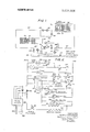
- FIG. l is a schematic view of a refrigeration and hot gas defrosting system embodying the principles of the present invention.
- FIG. 2 is a schematic wiring diagram of an electrical control circuit which may be used with the system of FIG. 1.
- the refrigeration system shown includes a compressor 10 of conventional construction, having a suction intake or low side 12 and a discharge or high side 14.
- the compressor discharge is connected through a discharge line or conduit 16 to the inlet of a condenser 18 cooled by means of fan 19.
- the condenser outlet is connected through a drain line 22 and a check valve 20 to a liquid refrigerant receiver 24.
- the receiver 24 is connected through a dip tube 26', a shutoff valve 28, a conduit 34, a liquid solenoid valve 30, and an expansion device 32, preferably of the thermostatic type, to the inlet side of an evaporator 36 having a motor driven fan 37.
- the evaporator 36 is of conventional construction, usually comprising a coil of copper tubing with extended fin surface.
- the outlet side of the evaporator 36 is connected through a suction line 42, a solenoid-operated valve 38, a suction pressure regulating valve 40 which may, for example, be a holdback valve or a thermostatic pressure control valve, to the suction side of the compressor 10.
- a first bypass conduit 44 is coupled into the circuit and to the liquid line 34 in bypassing relation to solenoid valve 30 and expansion device 32.
- a check valve 46 is provided in conduit 44 to prevent refrigerant from flowing through the conduit 44 during a normal refrigeration cycle. As will be explained hereinafter, however, refrigerant does flow through the check valve 46 in the op posite direction during a defrost cycle.
- a second bypass conduit 47 is coupled into the circuit and is connected between the discharge line H6 at the discharge side 14 of the compressor and the suction line 42.
- a second solenoid-operated valve 39 is included in the bypass 47 which, during a normal refrigeration cycle, prevents the flow of refrigerant through the bypass conduit 47.
- a third conduit 48 having a defrost solenoid valve 50 therein is connected between the receiver 24 and the junction of valves 38 and 40. The valve 50 prevents the flow of refrigerant through conduit 48 from the receiver 24 to the suction side of the compressor during a normal refrigeration cycle; but is open during a defrost cycle as will hereinafter be described.
- the evaporator 36 is provided with a drain pan 36A at the bottom thereof which receives the condensate formed on the evaporator coils. This condensate will drain down into the drain pan and may freeze when the evaporator is operated at an air temperature below 32 F. Accordingly, a drain pan heater, hereinafter described in connection with HO. 2, is provided for warming the drain pan during a defrost cycle.
- the evaporator 36 can be quickly and efficiently defrosted by the delivery of hot gas periodically thereto to internally heat the evaporator.
- means are associated with the receiver 24 for heating liquid refrigerant therein to maintain the refrigerant at sufficient pressure and temperature, which temperature may typically be about 65 to F., so that the refrigerant may serve as a source of heat during a defrost cycle in the system.
- an electric insert heater 52 is disposed within the receiver 24 to provide a source of heat for the liquid within the receiver.
- a pressure transducer device 54 senses the pressure within the receiver 24 and controls the power supplied to the heater 52. As the temperature of the liquid within the receiver increases, so also does the pressure.
- the device 54 can be replaced by a temperature measuring device, such as a thermistor, to control the power supplied to the heating element 52.
- the solenoid valves 38 and 30 are open while solenoid valves 39 and 50 are closed.
- the flow of refrigerant is from the compressor by way of discharge line 16 to the condenser 18, and from condenser 18 through drain line 22 and check valve to the receiver 24.
- liquid refrigerant is delivered through dip tube 26, shutoff valve 28, liquid line 34, and open solenoid valve to the expansion valve 32 which feeds liquid refrigerant to the evaporator 36.
- vaporized refrigerant is returned through suction line 42, solenoid valve 38 and suction pressure regulating valve 40 to the suction intake of compressor 10, completing the cycle.
- a timer closes the solenoid valves 38 and 30; while opening valves 39 and 50, at predetermined intervals of time.
- the refrigerant flow during the defrost cycle is from the upper vapor space of receiver 24 through solenoid valve 50, conduit 48 and valve 40 into the suction side 12 of the compressor 10.
- receiver pressure drops sharply, causing the formation of large vapor quantities in the receiver to feed the compressor.
- the refrigerant is then compressed by compressor 10, and passes through valve 39 and bypass line 47 into the suction line 42. Flow by way of discharge line 16 to the condenser 18 is minimized since the latter is at a relatively high pressure by comparison to the evaporator 36.
- the condenser fan is stopped by the timer during defrost to further reduce the ability of the condenser to receive vapor.
- Bypass line 47 is thus connected in bypassing relation to the condenser 18.
- the refrigerant flows through the suction line 42 into the outlet side of the evaporator 36 and thus through the evaporator 36 in a direction opposite that of the normal refrigeration cycle such that the evaporator functions as a condenser rejecting heat to frost formed on the evaporator.
- Condensed liquid from the evaporator 36 leaves by way of check valve 46, bypassing the expansion valve 32 and solenoid valve 30, which is now closed. From bypass line 44 the refrigerant flows through conduit 34 back into the receiver 24. If desired, flow to the condenser may be stopped by the addition of a solenoid valve or diverting valve in line 16.
- the circuit is automatically shifted to a postdefrost condition for a short interval immediately following defrost.
- defrost solenoid valve 50 is closed, solenoid valve 39 is closed and valves 38 and 30 are opened preparatory to a succeeding refrigeration cycle.
- the fans on the evaporator 36 remain stopped to complete drainage and permit the coil surface to cool down before refrigeration is resumed.
- the control circuit for the system of FIG. 1 is shown schematically. It includes a pair of terminals 70 and 72 adapted for connection to a source of potential, not shown. Connected between the terminals 70 and 72 is the motor 100 for compressor 10 in series with a lowpressure switch LP and a high-pressure switch HP, respectively. In shunt with the motor 10a is the motor 19a for the condenser fan 19 connected in series with a high-pressure cut-in switch 74. The switch 74 will close to start the fan 19 only when the pressure at the input to the condenser exceeds a predetermined value. During the defrost cycle, the pressure at the input to the condenser will be insufficient to maintain the switch 74 closed. Hence, the fan 19 will stop during a defrost cycle.
- the low-pressure switch LP is responsive to pressure in the suction line 42 and will open when the pressure in the suction line drops to the point where the compressor is pumping out the evaporator. This is a safety device; and, as was explained above, the low-pressure switch LP may sometimes trip due to a lack of sufficient pressure in the receiver 24, particularly where an ON-OFF heating cycle and resultant rise in pressure within the receiver is used. Similarly, a high-pressure safety switch HP is connected to the outlet side of the compressor 10 and will trip when the outlet pressure exceeds a predetermined value.
- a timer 60 which constantly runs and includes normally open contacts 64 and normally closed contacts 62.
- the timer 60 will periodically close contacts 64 and open contacts 62; however this can occur only if the timer release solenoid 66 is deenergized.
- the solenoid 30a for valve 30 is connected between power terminals 70 and 72 along with a thermostat 76 and a high-pressure safety cutout switch 78.
- the thermostat 76 is in the enclosure which is being refrigerated and will open or close depending upon the temperature therein. When it opens, the temperature has reached a predetermined maximum lower value, whereupon the valve 30 closes, the pressure in line 34 is reduced, and eventually the low-pressure switch LP opens to stop the compressor 10.
- thermostatic switch 68 At the coldest point on the evaporator 36 is a thermostatic switch 68 (see also FIG. 1). During a refrigeration cycle, the
- the timer 60 closes contacts 64 and opens contacts 62. With contacts 62 open, the motor 37a for the evaporator fan 37 is deenergiz ed and the fan stops. At the same time, opening of contacts 62 deenergizes the solenoid 38a for valve 38 to close the valve, while closing contacts 64 energizes the solenoid 50a for valve 50 to open that valve, and energizes the solenoid 39a for valve 39 to open that valve. At the same time, closure of contacts 64 energizes a drain pan heater coil 80 located in the drain pan 36A to maintain the pan sufficiently warm to prevent freezing of condensate therein during defrost.
- the defrost cycle will continue until the thermostat 68 senses a rise in temperature above a predetermined limit, whereupon the contacts on thermostatic switch 68 will be reversed; the timer release solenoid 66 will be energized and contacts 62 will close while contacts 64 open. With contacts 64 open, the positions of valves 50, 38 and 39 are reversed to again initiate a refrigeration cycle.
- the evaporator fans remain deenergized until thermostat 68 reverts to its cold position when the coil surface has again cooled down. This restarts fans 37a on the evaporator and the normal cooling cycle is resumed.
- the receiver heater 52 is connected between the power ter minals 70 and 72 through a pair of silicon controlled rectifiers 82 and 84 and a safety thermostatic switch 85.
- the silicon controlled rectifiers 82 and 84 are connected to a firing circuit 86 which, in turn, is controlled by the pressure sensing transducer device 54 disposed within the receiver 24.
- the firing circuit 86 could be responsive to the temperature sensed by a thermistor 88, for example, disposed within the receiver 24.
- the silicon controlled rectifiers 82 and 84 are similar in operation to thyratrons. That is, they can be triggered into conduction by means of pulses applied to their gate electrodes; but will shut off only when the voltage between their anodes and cathodes falls below a predetermined value. in this manner, the rectifier 82, for example, can be caused to tire after a predetermined lapse following initiation of the positive half cycle of the applied waveform; whereas the rectifier 84 can be caused to fire after a predetermined lapse following initiation of the negative half cycle of the applied waveform.
- the power supplied to the heater 52 will be dependent upon the point at which the rectifiers 82 and 84 fire during each half cycle and this, in turn, is dependent upon the pressure or temperature sensed by element 54 or 88, respectively. Since the element 54, for example, constantly senses pressure and immediately changes the phase firing angle of the rectifiers 82 and 841, the power supplied to the heater 52 is constantly varied as pressure varies, thereby maintaining the receiver pressure at a fixed level. This prevents a reduction in evaporator feeding rate and a consequent drop in pressure in the suction line 42 which might trip the low-pressure switch LP and shut off the compressor resulting in failure of the refrigeration system to function.
- the thermostat 85 is a safety device which will trip to deenergize the receiver heater whenever the temperature within the receiver exceeds a predetermined safe maximum value.
- the present invention thus provides a means for maintaining a constant pressure within the receiver 24 at all times by the use of silicon controlled rectifiers or the like which continually monitor the pressure and/or temperature within the receiver.
- a compression-type refrigeration system having a compressor, a condenser, a liquid refrigerant receiver, an expansion means and an evaporator interconnected to provide a closed circuit; the combination of means for heating refrigerant in said receiver to maintain the pressure therein at a predetermined level, means for varying the heat supplied to said receiver in analog fashion and as a function of a change in pressure in said receiver to maintain the pressure therein essentially constant, and the means for varying the heat supplied to the receiver including pressure transducer means within the receiver for controlling power to the heating means, whereby a fixed pressure is maintained within the receiver.
- heating means comprises an electrical heater and wherein the means for varying heat automatically modulates electrical power supplied to the heater so as to maintain a constant pressure in the receiver regardless of the ambient temperature surrounding the heater and regardless of the quantity of liquid added and withdrawn from the receiver.
Landscapes
- Physics & Mathematics (AREA)
- Engineering & Computer Science (AREA)
- Fluid Mechanics (AREA)
- General Physics & Mathematics (AREA)
- Automation & Control Theory (AREA)
- Mechanical Engineering (AREA)
- Thermal Sciences (AREA)
- General Engineering & Computer Science (AREA)
- Devices That Are Associated With Refrigeration Equipment (AREA)
- Defrosting Systems (AREA)
Abstract
Description
Claims (7)
Applications Claiming Priority (1)
| Application Number | Priority Date | Filing Date | Title |
|---|---|---|---|
| US887370A | 1970-02-05 | 1970-02-05 |
Publications (1)
| Publication Number | Publication Date |
|---|---|
| US3637005A true US3637005A (en) | 1972-01-25 |
Family
ID=21734190
Family Applications (1)
| Application Number | Title | Priority Date | Filing Date |
|---|---|---|---|
| US8873A Expired - Lifetime US3637005A (en) | 1970-02-05 | 1970-02-05 | Refrigeration defrost system with constant pressure heated receiver |
Country Status (1)
| Country | Link |
|---|---|
| US (1) | US3637005A (en) |
Cited By (9)
| Publication number | Priority date | Publication date | Assignee | Title |
|---|---|---|---|---|
| EP0229410A1 (en) * | 1985-12-12 | 1987-07-22 | S.A. Societe Financiere Valere Lecluse | Refrigeration machine |
| US4722195A (en) * | 1985-03-25 | 1988-02-02 | Matsushita Electric Industrial Co., Ltd. | Heat pump with a reservoir storing higher pressure refrigerant of non-azeotropic mixture |
| US5218830A (en) * | 1992-03-13 | 1993-06-15 | Uniflow Manufacturing Company | Split system ice-maker with remote condensing unit |
| US5806330A (en) * | 1995-12-05 | 1998-09-15 | Eaton Corporation | Method of controlling a refrigeration system and filter/drier/receiver therefor |
| US6599104B2 (en) * | 2000-09-29 | 2003-07-29 | Sanden Corporation | Motor-driven compressors |
| WO2012107773A3 (en) * | 2011-02-11 | 2012-11-29 | Frigesco Limited | Flash defrost system |
| CN104634012A (en) * | 2013-11-07 | 2015-05-20 | 珠海格力电器股份有限公司 | Flash-evaporation heat storage tank, air-conditioner unit provided with same, and heating method of air-conditioner unit |
| CN104634008A (en) * | 2013-11-14 | 2015-05-20 | 珠海格力电器股份有限公司 | Control method for air conditioner |
| CN104949409A (en) * | 2015-07-13 | 2015-09-30 | 金鑫 | System and method for flexibly defrosting air-source heat pump without starting compressor |
Citations (2)
| Publication number | Priority date | Publication date | Assignee | Title |
|---|---|---|---|---|
| US3238737A (en) * | 1964-03-31 | 1966-03-08 | Larkin Coils Inc | Heated receiver winter control for refrigeration systems |
| US3386498A (en) * | 1966-02-18 | 1968-06-04 | Statham Instrument Inc | Temperature control system |
-
1970
- 1970-02-05 US US8873A patent/US3637005A/en not_active Expired - Lifetime
Patent Citations (2)
| Publication number | Priority date | Publication date | Assignee | Title |
|---|---|---|---|---|
| US3238737A (en) * | 1964-03-31 | 1966-03-08 | Larkin Coils Inc | Heated receiver winter control for refrigeration systems |
| US3386498A (en) * | 1966-02-18 | 1968-06-04 | Statham Instrument Inc | Temperature control system |
Cited By (14)
| Publication number | Priority date | Publication date | Assignee | Title |
|---|---|---|---|---|
| US4722195A (en) * | 1985-03-25 | 1988-02-02 | Matsushita Electric Industrial Co., Ltd. | Heat pump with a reservoir storing higher pressure refrigerant of non-azeotropic mixture |
| EP0229410A1 (en) * | 1985-12-12 | 1987-07-22 | S.A. Societe Financiere Valere Lecluse | Refrigeration machine |
| US5218830A (en) * | 1992-03-13 | 1993-06-15 | Uniflow Manufacturing Company | Split system ice-maker with remote condensing unit |
| US5806330A (en) * | 1995-12-05 | 1998-09-15 | Eaton Corporation | Method of controlling a refrigeration system and filter/drier/receiver therefor |
| US6599104B2 (en) * | 2000-09-29 | 2003-07-29 | Sanden Corporation | Motor-driven compressors |
| CN103429974A (en) * | 2011-02-11 | 2013-12-04 | Frigesco有限公司 | Flash defrost system |
| WO2012107773A3 (en) * | 2011-02-11 | 2012-11-29 | Frigesco Limited | Flash defrost system |
| AU2012215130B2 (en) * | 2011-02-11 | 2017-07-27 | Frigesco Limited | Flash defrost system |
| CN104634012A (en) * | 2013-11-07 | 2015-05-20 | 珠海格力电器股份有限公司 | Flash-evaporation heat storage tank, air-conditioner unit provided with same, and heating method of air-conditioner unit |
| CN104634012B (en) * | 2013-11-07 | 2017-05-10 | 珠海格力电器股份有限公司 | Flash-evaporation heat storage tank, air-conditioner unit provided with same, and heating method of air-conditioner unit |
| CN104634008A (en) * | 2013-11-14 | 2015-05-20 | 珠海格力电器股份有限公司 | Control method for air conditioner |
| CN104634008B (en) * | 2013-11-14 | 2017-06-06 | 珠海格力电器股份有限公司 | The control method of air-conditioning device |
| CN104949409A (en) * | 2015-07-13 | 2015-09-30 | 金鑫 | System and method for flexibly defrosting air-source heat pump without starting compressor |
| CN104949409B (en) * | 2015-07-13 | 2017-03-29 | 金鑫 | A kind of flexible air source heat pump defrosting system and method that need not start compressor |
Similar Documents
| Publication | Publication Date | Title |
|---|---|---|
| US4286438A (en) | Condition responsive liquid line valve for refrigeration appliance | |
| US3844131A (en) | Refrigeration system with head pressure control | |
| US4197716A (en) | Refrigeration system with auxiliary heat exchanger for supplying heat during defrost cycle and for subcooling the refrigerant during a refrigeration cycle | |
| US4193781A (en) | Head pressure control for heat reclaim refrigeration systems | |
| US3918268A (en) | Heat pump with frost-free outdoor coil | |
| US5372011A (en) | Air conditioning and heat pump system utilizing thermal storage | |
| US4979371A (en) | Refrigeration system and method involving high efficiency gas defrost of plural evaporators | |
| US2492970A (en) | Defrosting system | |
| US3365902A (en) | Reverse cycle refrigeration system | |
| US2801523A (en) | Defrosting apparatus for refrigeration systems | |
| US3637005A (en) | Refrigeration defrost system with constant pressure heated receiver | |
| US3159981A (en) | Heat pump including frost control means | |
| US2728197A (en) | Defrosting control for refrigerating system | |
| US3371500A (en) | Refrigeration system starting | |
| US3739596A (en) | Refrigeration system including head pressure control means | |
| US2970816A (en) | Defrost arrangement for air conditioning apparatus | |
| US2573684A (en) | Refrigeration apparatus, including defrosting means | |
| US2178445A (en) | Refrigerating machine | |
| US2969959A (en) | Refrigerating apparatus | |
| US4517807A (en) | Heat pump water heater with supplemental heat supply | |
| US3774406A (en) | Condensate collector pan heating | |
| US2627730A (en) | Defrostable refrigeration system | |
| US3559421A (en) | Refrigeration defrost system with receiver heat source | |
| US3280579A (en) | Heat pump defrost control unit | |
| US2244376A (en) | Refrigerating system |
Legal Events
| Date | Code | Title | Description |
|---|---|---|---|
| AS | Assignment |
Owner name: SNYDER GENERAL CORPORATION, A CORP OF TX Free format text: ASSIGNMENT OF ASSIGNORS INTEREST.;ASSIGNOR:HALSTEAD INDUSTRIES, INC.;REEL/FRAME:004272/0317 Effective date: 19840503 |
|
| AS | Assignment |
Owner name: MCQUAY INC., A CORP. OF MINNESOTA, STATELESS Free format text: ASSIGNMENT OF ASSIGNORS INTEREST;ASSIGNOR:SNYDER GENERAL CORPORATION, A TX CORP.;REEL/FRAME:004607/0038 Effective date: 19860327 Owner name: MCQUAY INC., A CORP. OF MINNESOTA Free format text: ASSIGNMENT OF ASSIGNORS INTEREST.;ASSIGNOR:SNYDER GENERAL CORPORATION, A TX CORP.;REEL/FRAME:004607/0038 Effective date: 19860327 Owner name: SNYDER GENERAL CORPORATION, STATELESS Free format text: ASSIGNMENT OF ASSIGNORS INTEREST;ASSIGNOR:MCQUAY INC.;REEL/FRAME:004607/0047 Effective date: 19860327 Owner name: SNYDER GENERAL CORPORATION Free format text: ASSIGNMENT OF ASSIGNORS INTEREST.;ASSIGNOR:MCQUAY INC.;REEL/FRAME:004607/0047 Effective date: 19860327 |
|
| AS | Assignment |
Owner name: CITICORP INDUSTRIAL CREDIT INC.,TEXAS Free format text: SECURITY INTEREST;ASSIGNOR:SNYDERGENERAL CORPORATION;REEL/FRAME:004765/0735 Effective date: 19870630 Owner name: CITICORP INDUSTRIAL CREDIT INC., 2700 DIAMOND SHAM Free format text: SECURITY INTEREST;ASSIGNOR:SNYDERGENERAL CORPORATION;REEL/FRAME:004765/0735 Effective date: 19870630 |
|
| AS | Assignment |
Owner name: CITICORP NORTH AMERICA, INC., NEW YORK Free format text: SECURITY INTEREST;ASSIGNOR:SNYDERGENERAL CORPORATION, A MN CORP.;REEL/FRAME:005013/0592 Effective date: 19881117 |
|
| AS | Assignment |
Owner name: MCQUAY INC., A CORP. OF MINNESOTA, MINNESOTA Free format text: RELEASED BY SECURED PARTY;ASSIGNOR:CITICORP NORTH AMERICA, INC.;REEL/FRAME:005278/0013 Effective date: 19881117 Owner name: SNYDERGENERAL CORPORATION, A CORP. OF MINNESOTA, T Free format text: RELEASED BY SECURED PARTY;ASSIGNOR:CITICORP NORTH AMERICA, INC.;REEL/FRAME:005278/0013 Effective date: 19881117 |
|
| AS | Assignment |
Owner name: SNYDERGENERAL CORPORATION A CORP. OF DELAWARE Free format text: RELEASE BY SECOND PARTY OF A SECURITY AGREEMENT RECORDED AT REEL 5013 FRAME 592.;ASSIGNOR:CITICORP NORTH AMERICA, INC. A CORP. OF DELAWARE;REEL/FRAME:006104/0270 Effective date: 19920326 |